WO2013084763A1 - 希薄燃料吸入ガスタービン - Google Patents
希薄燃料吸入ガスタービン Download PDFInfo
- Publication number
- WO2013084763A1 WO2013084763A1 PCT/JP2012/080680 JP2012080680W WO2013084763A1 WO 2013084763 A1 WO2013084763 A1 WO 2013084763A1 JP 2012080680 W JP2012080680 W JP 2012080680W WO 2013084763 A1 WO2013084763 A1 WO 2013084763A1
- Authority
- WO
- WIPO (PCT)
- Prior art keywords
- gas
- catalyst
- fuel
- heat exchanger
- catalytic combustor
- Prior art date
- Legal status (The legal status is an assumption and is not a legal conclusion. Google has not performed a legal analysis and makes no representation as to the accuracy of the status listed.)
- Ceased
Links
Images
Classifications
-
- F—MECHANICAL ENGINEERING; LIGHTING; HEATING; WEAPONS; BLASTING
- F02—COMBUSTION ENGINES; HOT-GAS OR COMBUSTION-PRODUCT ENGINE PLANTS
- F02C—GAS-TURBINE PLANTS; AIR INTAKES FOR JET-PROPULSION PLANTS; CONTROLLING FUEL SUPPLY IN AIR-BREATHING JET-PROPULSION PLANTS
- F02C3/00—Gas-turbine plants characterised by the use of combustion products as the working fluid
- F02C3/04—Gas-turbine plants characterised by the use of combustion products as the working fluid having a turbine driving a compressor
-
- F—MECHANICAL ENGINEERING; LIGHTING; HEATING; WEAPONS; BLASTING
- F02—COMBUSTION ENGINES; HOT-GAS OR COMBUSTION-PRODUCT ENGINE PLANTS
- F02C—GAS-TURBINE PLANTS; AIR INTAKES FOR JET-PROPULSION PLANTS; CONTROLLING FUEL SUPPLY IN AIR-BREATHING JET-PROPULSION PLANTS
- F02C3/00—Gas-turbine plants characterised by the use of combustion products as the working fluid
- F02C3/20—Gas-turbine plants characterised by the use of combustion products as the working fluid using a special fuel, oxidant, or dilution fluid to generate the combustion products
- F02C3/22—Gas-turbine plants characterised by the use of combustion products as the working fluid using a special fuel, oxidant, or dilution fluid to generate the combustion products the fuel or oxidant being gaseous at standard temperature and pressure
-
- F—MECHANICAL ENGINEERING; LIGHTING; HEATING; WEAPONS; BLASTING
- F02—COMBUSTION ENGINES; HOT-GAS OR COMBUSTION-PRODUCT ENGINE PLANTS
- F02C—GAS-TURBINE PLANTS; AIR INTAKES FOR JET-PROPULSION PLANTS; CONTROLLING FUEL SUPPLY IN AIR-BREATHING JET-PROPULSION PLANTS
- F02C7/00—Features, components parts, details or accessories, not provided for in, or of interest apart form groups F02C1/00 - F02C6/00; Air intakes for jet-propulsion plants
- F02C7/08—Heating air supply before combustion, e.g. by exhaust gases
-
- F—MECHANICAL ENGINEERING; LIGHTING; HEATING; WEAPONS; BLASTING
- F02—COMBUSTION ENGINES; HOT-GAS OR COMBUSTION-PRODUCT ENGINE PLANTS
- F02C—GAS-TURBINE PLANTS; AIR INTAKES FOR JET-PROPULSION PLANTS; CONTROLLING FUEL SUPPLY IN AIR-BREATHING JET-PROPULSION PLANTS
- F02C9/00—Controlling gas-turbine plants; Controlling fuel supply in air- breathing jet-propulsion plants
- F02C9/26—Control of fuel supply
- F02C9/40—Control of fuel supply specially adapted to the use of a special fuel or a plurality of fuels
-
- F—MECHANICAL ENGINEERING; LIGHTING; HEATING; WEAPONS; BLASTING
- F23—COMBUSTION APPARATUS; COMBUSTION PROCESSES
- F23L—SUPPLYING AIR OR NON-COMBUSTIBLE LIQUIDS OR GASES TO COMBUSTION APPARATUS IN GENERAL ; VALVES OR DAMPERS SPECIALLY ADAPTED FOR CONTROLLING AIR SUPPLY OR DRAUGHT IN COMBUSTION APPARATUS; INDUCING DRAUGHT IN COMBUSTION APPARATUS; TOPS FOR CHIMNEYS OR VENTILATING SHAFTS; TERMINALS FOR FLUES
- F23L15/00—Heating of air supplied for combustion
-
- F—MECHANICAL ENGINEERING; LIGHTING; HEATING; WEAPONS; BLASTING
- F23—COMBUSTION APPARATUS; COMBUSTION PROCESSES
- F23R—GENERATING COMBUSTION PRODUCTS OF HIGH PRESSURE OR HIGH VELOCITY, e.g. GAS-TURBINE COMBUSTION CHAMBERS
- F23R3/00—Continuous combustion chambers using liquid or gaseous fuel
- F23R3/40—Continuous combustion chambers using liquid or gaseous fuel characterised by the use of catalytic means
-
- F—MECHANICAL ENGINEERING; LIGHTING; HEATING; WEAPONS; BLASTING
- F23—COMBUSTION APPARATUS; COMBUSTION PROCESSES
- F23N—REGULATING OR CONTROLLING COMBUSTION
- F23N2241/00—Applications
- F23N2241/20—Gas turbines
-
- Y—GENERAL TAGGING OF NEW TECHNOLOGICAL DEVELOPMENTS; GENERAL TAGGING OF CROSS-SECTIONAL TECHNOLOGIES SPANNING OVER SEVERAL SECTIONS OF THE IPC; TECHNICAL SUBJECTS COVERED BY FORMER USPC CROSS-REFERENCE ART COLLECTIONS [XRACs] AND DIGESTS
- Y02—TECHNOLOGIES OR APPLICATIONS FOR MITIGATION OR ADAPTATION AGAINST CLIMATE CHANGE
- Y02E—REDUCTION OF GREENHOUSE GAS [GHG] EMISSIONS, RELATED TO ENERGY GENERATION, TRANSMISSION OR DISTRIBUTION
- Y02E20/00—Combustion technologies with mitigation potential
- Y02E20/34—Indirect CO2mitigation, i.e. by acting on non CO2directly related matters of the process, e.g. pre-heating or heat recovery
Definitions
- the present invention sucks into the engine a low-calorie gas whose fuel concentration changes, such as methane gas generated in coal mines and landfills, as an air-fuel mixture having a flammable limit or less so as not to be ignited by compression with a compressor.
- the present invention relates to a lean fuel intake gas turbine that uses combustible components contained therein as fuel.
- a working gas containing fuel and having a flammable limit concentration or less is compressed by a compressor, and the compressed gas is combusted by a catalytic combustor and then supplied to the turbine to drive the turbine.
- the compressed gas introduced into the catalytic combustor from the compressor is heated by a heat exchanger using exhaust gas from the turbine (for example, Patent Document 1).
- VAM Vehicle Air Methane
- CMM Coal Mine Methane
- VAM has a low fuel concentration (methane concentration of less than 1%) and a small fluctuation range
- CMM has a high fuel concentration (methane concentration of 10 to 30%) and a large fluctuation range.
- the fuel concentration of the working gas that is the gas turbine intake that is, the fuel concentration of the compressed gas sucked into the catalytic combustor increases due to the variation of the CMM fuel concentration, the catalytic combustor may be burned out. If the concentration is low, there is a possibility of misfire in the catalytic combustor.
- the exhaust temperature that is, the heat exchanger is reduced by lowering the engine speed and reducing the intake flow rate.
- the inlet temperature is controlled so as not to drop.
- the control operation cannot follow the CMM fuel concentration fluctuation or load fluctuation due to the operation delay of the CMM fuel control valve and the reaction delay of the heat exchanger and the catalytic combustor. If the inlet temperature becomes too high, there is a high possibility that the catalytic combustor will burn out, and if it becomes low, there is a high possibility that the catalytic combustor will misfire.
- an object of the present invention is to provide a lean fuel intake gas that can be stably operated while avoiding burnout and misfire of the catalytic combustor even when the fuel concentration and load fluctuate. It is to provide a turbine.
- a lean fuel intake gas turbine includes a compressor that generates a compressed gas by compressing a working gas whose fuel concentration fluctuates below a flammable concentration limit, and catalyzing the compressed gas.
- a catalytic combustor to be combusted by the turbine a turbine driven by combustion gas from the catalytic combustor, a heat exchanger for heating the compressed gas introduced from the compressor to the catalytic combustor by exhaust gas from the turbine,
- a heat exchange bypass valve that communicates an inlet side and an outlet side of the compressed gas in the heat exchanger, and a first catalyst outlet that opens the heat exchange bypass valve when an outlet temperature of the catalytic combustor becomes equal to or higher than a predetermined outlet value.
- a temperature control unit a temperature control unit.
- the catalyst combustor when the catalyst outlet thermometer exceeds a specified value, the catalyst combustor is prevented from being burned by opening the heat exchange bypass valve to lower the catalyst inlet temperature. Further, when the catalyst outlet thermometer becomes less than the specified value, the catalyst combustor can be prevented from misfire by closing the heat exchanger bypass valve and raising the catalyst inlet temperature. As a result, even when the fuel concentration and the load fluctuate, the catalytic combustor can be stably operated while avoiding burnout and misfire.
- the burnout of the catalytic combustor can be more effectively prevented by combining the control of the concentration adjusting unit and the heat exchange bypass valve.
- it further comprises a catalyst inlet temperature control unit that closes the heat exchange bypass valve when the inlet temperature of the catalytic combustor becomes equal to or lower than a predetermined inlet value with the heat exchange bypass valve open.
- a catalyst inlet temperature control unit that closes the heat exchange bypass valve when the inlet temperature of the catalytic combustor becomes equal to or lower than a predetermined inlet value with the heat exchange bypass valve open.
- the working gas is a mixture of a plurality of fuel gases having different fuel concentrations, and when the outlet temperature of the catalytic combustor becomes equal to or higher than an outlet predetermined value, one or more of the fuel concentrations having a higher concentration are provided. It is preferable to provide a second catalyst outlet temperature controller that suppresses the amount of fuel supplied. According to this configuration, even when a plurality of fuel gases having different fuel concentrations are mixed, it is possible to easily prevent burning of the catalytic combustor by suppressing the supply amount of one or more fuels having a high fuel concentration. .
- the working gas is preferably a mixture of coal mine aeration methane gas (VAM) and coal mine methane gas (CMM). According to this configuration, it is possible to prevent VAM and CMM from being released into the atmosphere and effectively use them as fuel.
- VAM coal mine aeration methane gas
- CMM coal mine methane gas
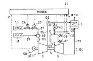
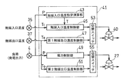
- FIG. 1 is a block diagram showing a schematic configuration of a lean fuel intake gas turbine according to an embodiment of the present invention. It is a block diagram which shows schematic structure of the control apparatus of the gas turbine of FIG.
- FIG. 1 is a schematic configuration diagram showing a lean fuel intake gas turbine GT according to an embodiment of the present invention.
- the gas turbine GT includes a compressor 1, a catalytic combustor 2 including a catalyst such as platinum or palladium, and a turbine 3.
- the generator 4 is driven by the gas turbine GT.
- a VAM generated in a coal mine and a fuel gas having two different fuel concentrations such as CMM having a higher combustible component (methane) concentration are mixed.
- the obtained working gas G1 has a fuel concentration that varies greatly depending on the state of the coal mine.
- the working gas G ⁇ b> 1 is introduced into the intake inlet of the gas turbine GT and is compressed by the compressor 1, and the high-pressure compressed gas G ⁇ b> 2 is sent to the catalytic combustor 2.
- the compressed gas G2 is combusted by a catalytic reaction by a catalyst such as platinum or palladium in the catalytic combustor 2, and a high-temperature / high-pressure combustion gas G3 generated thereby is supplied to the turbine 3 to drive the turbine 3.
- the turbine 3 is connected to the compressor 1 via the rotary shaft 5, and the compressor 1 is driven by the turbine 3.
- the power generation device 50 including the gas turbine GT and the power generator 4 is configured.
- the heat exchanger 6 is provided in the exhaust passage 23 of the gas turbine GT.
- the heat exchanger 6 heats the compressed gas G ⁇ b> 2 introduced from the compressor 1 to the catalytic combustor 2 by the exhaust gas G ⁇ b> 4 from the turbine 3.
- the fuel supply system to the gas turbine GT is compressed by mixing a suitable amount of CMM with a higher methane concentration (usually 20-30%) into a VAM with a lower methane concentration (less than 1%, usually around 0.5%).
- the fuel supply system includes a fuel main supply path 13 that is connected from the VAM supply source 11 to the compressor 1 and a fuel sub-line that communicates from the CMM supply source 15 to the main supply path 13 via various valves described later.
- a supply path 17 is provided. Mixing of the CMM from the fuel sub supply path 17 to the fuel main supply path 13 is performed by a mixer 19 provided in the middle of the fuel main supply path 13.
- the sub fuel supply path 17 is provided with a CMM fuel control valve 27 for adjusting the flow rate of the CMM fuel, and the flow of the CMM fuel is interrupted upstream of the CMM fuel control valve 27 in the fuel sub supply path 17.
- a fuel cutoff valve 33 is provided.
- the CMM fuel control valve 27 forms a concentration adjusting unit that adjusts the fuel concentration of the working gas G1.
- a bypass passage 31 is provided to communicate a compressed gas inlet passage 25 connecting the compressor 1 and the heat exchanger 6 and a compressed gas outlet passage 29 connecting the heat exchanger 6 and the catalytic combustor 2, and the bypass passage is provided.
- a heat exchange bypass valve 40 is provided at 31. Details of the heat exchanger bypass valve 40 will be described later. Further, a catalyst inlet thermometer 35 and a catalyst outlet thermometer 37 are provided at the inlet and outlet of the catalyst combustor 2, respectively.
- Each temperature value detected by the catalyst inlet thermometer 35 and the catalyst outlet thermometer 37 is sent to the control device 41. Further, the power generation output value of the generator 4 is also sent to the control device 41. Based on these input values, the control device 41 adjusts the CMM fuel control valve 27, the fuel cutoff valve 33, the first fuel control valve 27, and the heat exchanger bypass valve 40 to supply the inlet to the catalytic combustor 2. The temperature of the compressed gas G2 to be controlled is controlled.
- the control device 41 includes a catalyst inlet temperature setting unit 43 that sets the optimum catalyst inlet temperature T from the load P of the generator 4, and the set optimum catalyst inlet temperature T and the catalyst inlet thermometer 35.
- a catalyst inlet temperature controller 45 that controls the heat exchanger bypass valve 40 from the measured value Ti, and a first catalyst outlet temperature controller that controls the temperature of the heat exchanger bypass valve 40 based on the measured value To of the catalyst outlet thermometer 37.
- the control device 41 further switches the control mode of the heat exchanger bypass valve 40 to catalyst inlet temperature control or first catalyst outlet temperature control, and the control mode of the CMM fuel control valve 27 to power control or second catalyst.
- a fuel control valve switching switch 55 that switches to outlet temperature control is provided.
- the normal heat exchange bypass valve 40 is controlled by catalyst inlet temperature control. That is, the bypass valve selector switch 53 is switched to the catalyst inlet temperature control unit 45 side. Specifically, the heat exchanger bypass valve 40 is adjusted according to the measured value of the catalyst inlet thermometer 35 so that the temperature at which the catalyst can react stably is obtained. Since the temperature at which the catalyst can react stably depends on the power generation output as a load, that is, the fuel concentration, the catalyst inlet temperature setting unit 43 calculates the optimum catalyst inlet temperature setting value T from the measured value P of the power generation output, The set value of the catalyst temperature inlet control by the alternating bypass valve 40 is used. The heat exchanger bypass valve 40 is adjusted by the catalyst inlet temperature control unit 45 so that the measured value Ti of the catalyst inlet thermometer 35 approaches the optimum catalyst inlet temperature T.
- the normal CMM fuel control valve 27 is operated by electric power control. That is, the fuel control valve switch 55 is switched to the power control unit 49 side. Specifically, the CMM fuel control valve 27 is adjusted by the power control unit 49 so as to achieve an optimum rotational speed according to the load P of the generator 4.
- the fuel concentration of the working gas G1 and the temperature (exhaust gas temperature) of the exhaust gas G4 in FIG. 1 are changed while the CMM fuel concentration suddenly increases or the engine speed is changed.
- the measured value To of the catalyst outlet thermometer 37 in FIG. 2 is equal to or higher than the heat resistance temperature of the catalyst due to factors such as becoming too high, the heat exchange bypass valve 40 and the CMM fuel control valve 27 are respectively controlled as follows. I do.
- the bypass valve changeover switch 53 is switched to the first catalyst outlet temperature control unit 47 side, and the control mode of the heat exchanger bypass valve 40 is set to catalyst outlet temperature control. Specifically, the heat exchange bypass valve 40 is opened by the first catalyst outlet temperature control unit 47, and the compressed gas inlet passage 25 and the compressed gas outlet passage 29 are communicated with each other via the bypass passage 31 of FIG. Bypass.
- the compressed gas G2 that has been heated through the heat exchanger 6 is mixed with the low-temperature compressed gas G2 that has not yet passed through the heat exchanger 6, and the compressed gas G2 that is introduced into the catalytic combustor 2 is mixed. , I.e., the temperature of the catalyst inlet thermometer 35 decreases.
- the temperature of the catalyst outlet thermometer 37 also decreases.
- the heat exchange bypass valve 40 is closed by the first catalyst outlet temperature control unit 47 of FIG.
- the heat resistant temperature of the catalyst is, for example, about 950 ° C.
- the optimum catalyst outlet temperature is, for example, about 700 to 900 ° C.
- the fuel control valve changeover switch 55 is switched to the second catalyst outlet temperature controller 51 side, and the control mode of the CMM fuel control valve 27 is set to catalyst outlet temperature control.
- the CMM fuel control valve 27 is closed by the second catalyst outlet temperature controller 51, and the methane concentration of the working gas G1 supplied to the gas turbine GT of FIG. The temperature drops.
- the CMM fuel control valve 27 is opened by the second catalyst outlet temperature control unit 51 of FIG.
- the catalyst outlet temperature is lowered by simultaneously controlling both the heat exchange bypass valve 40 and the CMM fuel control valve 27.
- the control of the CMM fuel control valve 27 is omitted and the heat exchange bypass is performed. Only the control of the valve 40 may be performed.
- the heat exchanger bypass valve 40 performs the following control. .
- the catalyst inlet temperature control unit 45 is switched to the catalyst inlet temperature control unit 45 side to change the control mode of the heat exchanger bypass valve 40 to catalyst inlet temperature control.
- the heat exchanger bypass valve 40 is closed by the catalyst inlet temperature control unit 45, and the temperature of the catalyst inlet thermometer 35 increases.
- the measured value Ti of the catalyst inlet thermometer 35 becomes a temperature at which the catalytic reaction is possible.
- the optimum catalyst inlet temperature T is, for example, about 400 ° C.
- the catalyst inlet temperature control unit 45 may be omitted, and the heat exchanger bypass valve 40 may be closed when the outlet temperature To of the catalyst combustor 2 becomes equal to or lower than a specified value lower than the specified outlet value.
- the catalyst combustor 2 when the measured value To of the catalyst outlet thermometer 37 in FIG. 1 is equal to or higher than the catalyst heat resistance temperature, the catalyst combustor 2 is prevented from being burned by opening the heat exchange bypass valve 40 and lowering the catalyst inlet temperature.
- the measured value Ti of the catalyst inlet thermometer 35 reaches a temperature at which the catalytic reaction cannot be performed, the catalyst combustor 2 is prevented from being misfired by closing the heat exchange bypass valve 40 and raising the catalyst inlet temperature. This makes it possible to stably operate the gas turbine GT while avoiding burning and misfire of the catalytic combustor 2 even when the CMM concentration and the load vary.
- the methane concentration of the working gas G1 is lowered by closing the CMM fuel control valve 27, and the burning of the catalytic combustor 2 is more effective. Can be prevented.
- the catalytic combustor 2 can be easily prevented from being burned out.
- VAM and CMM are used as the working gas G1, it is possible to prevent VAM and CMM from being released into the atmosphere and to achieve effective use as fuel.
- the working gas G1 may be a mixture of three or more types of fuel gas, for example, VAM, CMM, and natural gas.
- the working gas G1 is a mixture of air and fuel whose fuel concentration varies.
- control is performed so as to suppress the supply amount of one or more richer fuel gases.
Landscapes
- Engineering & Computer Science (AREA)
- Chemical & Material Sciences (AREA)
- Combustion & Propulsion (AREA)
- Mechanical Engineering (AREA)
- General Engineering & Computer Science (AREA)
- Chemical Kinetics & Catalysis (AREA)
- Exhaust Gas After Treatment (AREA)
- Engine Equipment That Uses Special Cycles (AREA)
- Control Of Turbines (AREA)
Abstract
Description
2 触媒燃焼器
3 タービン
4 発電機
6 熱交換器
27 CMM燃料制御弁(濃度調節部)
35 触媒入口温度計
37 触媒出口温度計
40 熱交バイパス弁
41 制御装置
45 触媒入口温度制御部
47 第1触媒出口温度制御部
51 第2触媒出口温度制御部
GT 希薄燃料吸入ガスタービン
G1 作動ガス
G2 圧縮ガス
G3 燃焼ガス
G4 排ガス
Claims (5)
- 燃料濃度の変動する作動ガスを可燃濃度限界以下で圧縮して圧縮ガスを生成する圧縮機と、
前記圧縮ガスを触媒反応により燃焼させる触媒燃焼器と、
前記触媒燃焼器からの燃焼ガスにより駆動されるタービンと、
前記タービンからの排ガスによって前記圧縮機から触媒燃焼器に導入される圧縮ガスを加熱する熱交換器と、
前記熱交換器における圧縮ガスの入口側と出口側とを連通させる熱交バイパス弁と、
前記触媒燃焼器の出口温度が出口規定値以上になったとき前記熱交バイパス弁を開く第1触媒出口温度制御部と、
を備えた希薄燃料吸入ガスタービン。 - 請求項1において、さらに、前記触媒燃焼器の出口温度が出口規定値以上になったとき、前記作動ガスの燃料濃度を低下させる濃度調節部を備えた希薄燃料吸入ガスタービン。
- 請求項1において、さらに、前記熱交バイパス弁が開いている状態で前記触媒燃焼器の入口温度が入口規定値以下になったとき、前記熱交バイパス弁を閉じる触媒入口温度制御部を備えた希薄燃料吸入ガスタービン。
- 請求項1において、前記作動ガスは燃料濃度の異なる複数の燃料ガスが混合されたものであり、
前記触媒燃焼器の出口温度が出口規定値以上になったとき、燃料濃度の濃い方の1つ以上の燃料の供給量を抑制する第2触媒出口温度制御部を備えた希薄燃料吸入ガスタービン。 - 請求項1において、前記作動ガスは炭鉱通気メタンガスと炭鉱メタンガスとの混合気である希薄燃料吸入ガスタービン。
Priority Applications (3)
| Application Number | Priority Date | Filing Date | Title |
|---|---|---|---|
| AU2012349638A AU2012349638B2 (en) | 2011-12-05 | 2012-11-28 | Lean fuel intake gas turbine engine |
| CN201280058278.3A CN103958857B (zh) | 2011-12-05 | 2012-11-28 | 贫燃料吸入燃气轮机 |
| US14/362,224 US20140331640A1 (en) | 2011-12-05 | 2012-11-28 | Lean fuel intake gas turbine engine |
Applications Claiming Priority (2)
| Application Number | Priority Date | Filing Date | Title |
|---|---|---|---|
| JP2011-265522 | 2011-12-05 | ||
| JP2011265522A JP5183795B1 (ja) | 2011-12-05 | 2011-12-05 | 希薄燃料吸入ガスタービン |
Publications (1)
| Publication Number | Publication Date |
|---|---|
| WO2013084763A1 true WO2013084763A1 (ja) | 2013-06-13 |
Family
ID=48481373
Family Applications (1)
| Application Number | Title | Priority Date | Filing Date |
|---|---|---|---|
| PCT/JP2012/080680 Ceased WO2013084763A1 (ja) | 2011-12-05 | 2012-11-28 | 希薄燃料吸入ガスタービン |
Country Status (5)
| Country | Link |
|---|---|
| US (1) | US20140331640A1 (ja) |
| JP (1) | JP5183795B1 (ja) |
| CN (1) | CN103958857B (ja) |
| AU (1) | AU2012349638B2 (ja) |
| WO (1) | WO2013084763A1 (ja) |
Cited By (1)
| Publication number | Priority date | Publication date | Assignee | Title |
|---|---|---|---|---|
| JP2018178803A (ja) * | 2017-04-07 | 2018-11-15 | 三菱日立パワーシステムズ株式会社 | ガスタービン制御装置、ガスタービン、及びガスタービン制御方法 |
Families Citing this family (7)
| Publication number | Priority date | Publication date | Assignee | Title |
|---|---|---|---|---|
| RU2014129254A (ru) * | 2011-12-22 | 2016-02-20 | Кавасаки Дзюкогё Кабусики Кайся | Способ работы газотурбинного двигателя с питанием обедненным топливом и электрогенераторное устройство на основе газовой турбины |
| JP6220589B2 (ja) * | 2013-07-26 | 2017-10-25 | 8 リバーズ キャピタル,エルエルシー | ガスタービン設備 |
| JP6250332B2 (ja) | 2013-08-27 | 2017-12-20 | 8 リバーズ キャピタル,エルエルシー | ガスタービン設備 |
| DE102016201974A1 (de) * | 2016-02-10 | 2017-08-10 | Dürr Systems Ag | Verfahren zum Betreiben einer Wärmekraftmaschine und Wärmekraftmaschine |
| JP7193962B2 (ja) * | 2018-09-26 | 2022-12-21 | 三菱重工業株式会社 | 燃焼器及びこれを備えたガスタービン |
| CN109281761A (zh) * | 2018-12-04 | 2019-01-29 | 新奥能源动力科技(上海)有限公司 | 一种燃烧室试验系统 |
| JP2022003243A (ja) * | 2020-06-23 | 2022-01-11 | 東芝エネルギーシステムズ株式会社 | ガスタービン設備 |
Citations (5)
| Publication number | Priority date | Publication date | Assignee | Title |
|---|---|---|---|---|
| JPS6334424A (ja) * | 1986-07-30 | 1988-02-15 | Hitachi Ltd | ガスタ−ビン用触媒燃焼器の燃料制御方法 |
| JPH062850A (ja) * | 1992-06-22 | 1994-01-11 | Central Res Inst Of Electric Power Ind | 触媒燃焼器 |
| JP2007500815A (ja) * | 2003-07-31 | 2007-01-18 | メス インターナショナル,インコーポレイテッド | 触媒燃焼を採用する回収熱交換式ガスタービンエンジンシステム及び方法 |
| JP2010019247A (ja) * | 2008-06-13 | 2010-01-28 | Kawasaki Heavy Ind Ltd | 希薄燃料吸入ガスタービン |
| JP4751950B1 (ja) * | 2010-03-24 | 2011-08-17 | 川崎重工業株式会社 | 希薄燃料吸入ガスタービン |
Family Cites Families (5)
| Publication number | Priority date | Publication date | Assignee | Title |
|---|---|---|---|---|
| GB2014662A (en) * | 1978-02-16 | 1979-08-30 | English Electric Co Ltd | Gas Turbine Plant Providing Shaft Power and Heat |
| JP2891055B2 (ja) * | 1993-09-16 | 1999-05-17 | 日産自動車株式会社 | 発電機の制御装置 |
| US5845481A (en) * | 1997-01-24 | 1998-12-08 | Westinghouse Electric Corporation | Combustion turbine with fuel heating system |
| US20100175379A1 (en) * | 2009-01-09 | 2010-07-15 | General Electric Company | Pre-mix catalytic partial oxidation fuel reformer for staged and reheat gas turbine systems |
| JP4841679B2 (ja) * | 2010-04-15 | 2011-12-21 | 川崎重工業株式会社 | ガスタービンの制御装置 |
-
2011
- 2011-12-05 JP JP2011265522A patent/JP5183795B1/ja not_active Expired - Fee Related
-
2012
- 2012-11-28 WO PCT/JP2012/080680 patent/WO2013084763A1/ja not_active Ceased
- 2012-11-28 AU AU2012349638A patent/AU2012349638B2/en not_active Ceased
- 2012-11-28 US US14/362,224 patent/US20140331640A1/en not_active Abandoned
- 2012-11-28 CN CN201280058278.3A patent/CN103958857B/zh not_active Expired - Fee Related
Patent Citations (5)
| Publication number | Priority date | Publication date | Assignee | Title |
|---|---|---|---|---|
| JPS6334424A (ja) * | 1986-07-30 | 1988-02-15 | Hitachi Ltd | ガスタ−ビン用触媒燃焼器の燃料制御方法 |
| JPH062850A (ja) * | 1992-06-22 | 1994-01-11 | Central Res Inst Of Electric Power Ind | 触媒燃焼器 |
| JP2007500815A (ja) * | 2003-07-31 | 2007-01-18 | メス インターナショナル,インコーポレイテッド | 触媒燃焼を採用する回収熱交換式ガスタービンエンジンシステム及び方法 |
| JP2010019247A (ja) * | 2008-06-13 | 2010-01-28 | Kawasaki Heavy Ind Ltd | 希薄燃料吸入ガスタービン |
| JP4751950B1 (ja) * | 2010-03-24 | 2011-08-17 | 川崎重工業株式会社 | 希薄燃料吸入ガスタービン |
Cited By (1)
| Publication number | Priority date | Publication date | Assignee | Title |
|---|---|---|---|---|
| JP2018178803A (ja) * | 2017-04-07 | 2018-11-15 | 三菱日立パワーシステムズ株式会社 | ガスタービン制御装置、ガスタービン、及びガスタービン制御方法 |
Also Published As
| Publication number | Publication date |
|---|---|
| AU2012349638B2 (en) | 2015-07-30 |
| US20140331640A1 (en) | 2014-11-13 |
| JP2013117202A (ja) | 2013-06-13 |
| AU2012349638A1 (en) | 2014-07-17 |
| CN103958857B (zh) | 2016-05-11 |
| JP5183795B1 (ja) | 2013-04-17 |
| CN103958857A (zh) | 2014-07-30 |
Similar Documents
| Publication | Publication Date | Title |
|---|---|---|
| JP5183795B1 (ja) | 希薄燃料吸入ガスタービン | |
| JP4751950B1 (ja) | 希薄燃料吸入ガスタービン | |
| JP4538077B2 (ja) | 希薄燃料吸入ガスタービン | |
| CN103775215B (zh) | 操作具有顺序燃烧的燃气涡轮的方法及燃气涡轮 | |
| US9500127B2 (en) | Power plant and method for its operation | |
| US20140298818A1 (en) | Control method and control device for lean fuel intake gas turbine | |
| AU2012355053A1 (en) | Method for operating lean fuel intake gas turbine engine, and gas turbine power generation device | |
| CN103857891B (zh) | 贫燃料吸入燃气轮机 | |
| JP5843578B2 (ja) | ガス混合気供給システム | |
| AU2012327119A1 (en) | Low-concentration methane gas oxidation system using gas turbine engine waste heat | |
| WO2013147944A2 (en) | Compressor guide vane and pilot control for gas turbine engine | |
| CN201145277Y (zh) | 一种低热值燃气燃烧器 | |
| JP5592965B2 (ja) | 希薄燃料吸入ガスタービンの制御方法および制御装置 | |
| JP4795999B2 (ja) | ガスタービン発電システム | |
| JP2012057593A (ja) | 燃料混合気供給システムおよびバイオガス発電システム | |
| JP2015227653A (ja) | バイオマスガス専焼エンジン | |
| JP2005147136A (ja) | ガスタービンの燃料制御装置 |
Legal Events
| Date | Code | Title | Description |
|---|---|---|---|
| WWE | Wipo information: entry into national phase |
Ref document number: 201280058278.3 Country of ref document: CN |
|
| 121 | Ep: the epo has been informed by wipo that ep was designated in this application |
Ref document number: 12856167 Country of ref document: EP Kind code of ref document: A1 |
|
| WWE | Wipo information: entry into national phase |
Ref document number: 14362224 Country of ref document: US |
|
| NENP | Non-entry into the national phase |
Ref country code: DE |
|
| WWE | Wipo information: entry into national phase |
Ref document number: A201407496 Country of ref document: UA |
|
| ENP | Entry into the national phase |
Ref document number: 2014126729 Country of ref document: RU Kind code of ref document: A |
|
| ENP | Entry into the national phase |
Ref document number: 2012349638 Country of ref document: AU Date of ref document: 20121128 Kind code of ref document: A |
|
| 122 | Ep: pct application non-entry in european phase |
Ref document number: 12856167 Country of ref document: EP Kind code of ref document: A1 |