WO2013084673A1 - 充放電制御装置、充電制御方法、放電制御方法、及びプログラム - Google Patents
充放電制御装置、充電制御方法、放電制御方法、及びプログラム Download PDFInfo
- Publication number
- WO2013084673A1 WO2013084673A1 PCT/JP2012/079364 JP2012079364W WO2013084673A1 WO 2013084673 A1 WO2013084673 A1 WO 2013084673A1 JP 2012079364 W JP2012079364 W JP 2012079364W WO 2013084673 A1 WO2013084673 A1 WO 2013084673A1
- Authority
- WO
- WIPO (PCT)
- Prior art keywords
- power
- secondary battery
- charge
- peak cut
- power value
- Prior art date
- Legal status (The legal status is an assumption and is not a legal conclusion. Google has not performed a legal analysis and makes no representation as to the accuracy of the status listed.)
- Ceased
Links
Images
Classifications
-
- B—PERFORMING OPERATIONS; TRANSPORTING
- B60—VEHICLES IN GENERAL
- B60L—PROPULSION OF ELECTRICALLY-PROPELLED VEHICLES; SUPPLYING ELECTRIC POWER FOR AUXILIARY EQUIPMENT OF ELECTRICALLY-PROPELLED VEHICLES; ELECTRODYNAMIC BRAKE SYSTEMS FOR VEHICLES IN GENERAL; MAGNETIC SUSPENSION OR LEVITATION FOR VEHICLES; MONITORING OPERATING VARIABLES OF ELECTRICALLY-PROPELLED VEHICLES; ELECTRIC SAFETY DEVICES FOR ELECTRICALLY-PROPELLED VEHICLES
- B60L7/00—Electrodynamic brake systems for vehicles in general
- B60L7/10—Dynamic electric regenerative braking
- B60L7/14—Dynamic electric regenerative braking for vehicles propelled by AC motors
-
- B—PERFORMING OPERATIONS; TRANSPORTING
- B60—VEHICLES IN GENERAL
- B60L—PROPULSION OF ELECTRICALLY-PROPELLED VEHICLES; SUPPLYING ELECTRIC POWER FOR AUXILIARY EQUIPMENT OF ELECTRICALLY-PROPELLED VEHICLES; ELECTRODYNAMIC BRAKE SYSTEMS FOR VEHICLES IN GENERAL; MAGNETIC SUSPENSION OR LEVITATION FOR VEHICLES; MONITORING OPERATING VARIABLES OF ELECTRICALLY-PROPELLED VEHICLES; ELECTRIC SAFETY DEVICES FOR ELECTRICALLY-PROPELLED VEHICLES
- B60L50/00—Electric propulsion with power supplied within the vehicle
- B60L50/50—Electric propulsion with power supplied within the vehicle using propulsion power supplied by batteries or fuel cells
- B60L50/51—Electric propulsion with power supplied within the vehicle using propulsion power supplied by batteries or fuel cells characterised by AC-motors
-
- B—PERFORMING OPERATIONS; TRANSPORTING
- B60—VEHICLES IN GENERAL
- B60L—PROPULSION OF ELECTRICALLY-PROPELLED VEHICLES; SUPPLYING ELECTRIC POWER FOR AUXILIARY EQUIPMENT OF ELECTRICALLY-PROPELLED VEHICLES; ELECTRODYNAMIC BRAKE SYSTEMS FOR VEHICLES IN GENERAL; MAGNETIC SUSPENSION OR LEVITATION FOR VEHICLES; MONITORING OPERATING VARIABLES OF ELECTRICALLY-PROPELLED VEHICLES; ELECTRIC SAFETY DEVICES FOR ELECTRICALLY-PROPELLED VEHICLES
- B60L55/00—Arrangements for supplying energy stored within a vehicle to a power network, i.e. vehicle-to-grid [V2G] arrangements
-
- H—ELECTRICITY
- H01—ELECTRIC ELEMENTS
- H01M—PROCESSES OR MEANS, e.g. BATTERIES, FOR THE DIRECT CONVERSION OF CHEMICAL ENERGY INTO ELECTRICAL ENERGY
- H01M10/00—Secondary cells; Manufacture thereof
- H01M10/42—Methods or arrangements for servicing or maintenance of secondary cells or secondary half-cells
- H01M10/46—Accumulators structurally combined with charging apparatus
-
- H—ELECTRICITY
- H02—GENERATION; CONVERSION OR DISTRIBUTION OF ELECTRIC POWER
- H02J—CIRCUIT ARRANGEMENTS OR SYSTEMS FOR SUPPLYING OR DISTRIBUTING ELECTRIC POWER; SYSTEMS FOR STORING ELECTRIC ENERGY
- H02J7/00—Circuit arrangements for charging or depolarising batteries or for supplying loads from batteries
- H02J7/14—Circuit arrangements for charging or depolarising batteries or for supplying loads from batteries for charging batteries from dynamo-electric generators driven at varying speed, e.g. on vehicle
- H02J7/1469—Regulation of the charging current or voltage otherwise than by variation of field
-
- H02J7/865—
-
- B—PERFORMING OPERATIONS; TRANSPORTING
- B60—VEHICLES IN GENERAL
- B60L—PROPULSION OF ELECTRICALLY-PROPELLED VEHICLES; SUPPLYING ELECTRIC POWER FOR AUXILIARY EQUIPMENT OF ELECTRICALLY-PROPELLED VEHICLES; ELECTRODYNAMIC BRAKE SYSTEMS FOR VEHICLES IN GENERAL; MAGNETIC SUSPENSION OR LEVITATION FOR VEHICLES; MONITORING OPERATING VARIABLES OF ELECTRICALLY-PROPELLED VEHICLES; ELECTRIC SAFETY DEVICES FOR ELECTRICALLY-PROPELLED VEHICLES
- B60L2200/00—Type of vehicles
- B60L2200/26—Rail vehicles
-
- B—PERFORMING OPERATIONS; TRANSPORTING
- B60—VEHICLES IN GENERAL
- B60L—PROPULSION OF ELECTRICALLY-PROPELLED VEHICLES; SUPPLYING ELECTRIC POWER FOR AUXILIARY EQUIPMENT OF ELECTRICALLY-PROPELLED VEHICLES; ELECTRODYNAMIC BRAKE SYSTEMS FOR VEHICLES IN GENERAL; MAGNETIC SUSPENSION OR LEVITATION FOR VEHICLES; MONITORING OPERATING VARIABLES OF ELECTRICALLY-PROPELLED VEHICLES; ELECTRIC SAFETY DEVICES FOR ELECTRICALLY-PROPELLED VEHICLES
- B60L2210/00—Converter types
- B60L2210/10—DC to DC converters
-
- H—ELECTRICITY
- H01—ELECTRIC ELEMENTS
- H01M—PROCESSES OR MEANS, e.g. BATTERIES, FOR THE DIRECT CONVERSION OF CHEMICAL ENERGY INTO ELECTRICAL ENERGY
- H01M10/00—Secondary cells; Manufacture thereof
- H01M10/42—Methods or arrangements for servicing or maintenance of secondary cells or secondary half-cells
- H01M10/44—Methods for charging or discharging
-
- H—ELECTRICITY
- H01—ELECTRIC ELEMENTS
- H01M—PROCESSES OR MEANS, e.g. BATTERIES, FOR THE DIRECT CONVERSION OF CHEMICAL ENERGY INTO ELECTRICAL ENERGY
- H01M2220/00—Batteries for particular applications
- H01M2220/20—Batteries in motive systems, e.g. vehicle, ship, plane
-
- H02J7/933—
-
- Y—GENERAL TAGGING OF NEW TECHNOLOGICAL DEVELOPMENTS; GENERAL TAGGING OF CROSS-SECTIONAL TECHNOLOGIES SPANNING OVER SEVERAL SECTIONS OF THE IPC; TECHNICAL SUBJECTS COVERED BY FORMER USPC CROSS-REFERENCE ART COLLECTIONS [XRACs] AND DIGESTS
- Y02—TECHNOLOGIES OR APPLICATIONS FOR MITIGATION OR ADAPTATION AGAINST CLIMATE CHANGE
- Y02E—REDUCTION OF GREENHOUSE GAS [GHG] EMISSIONS, RELATED TO ENERGY GENERATION, TRANSMISSION OR DISTRIBUTION
- Y02E60/00—Enabling technologies; Technologies with a potential or indirect contribution to GHG emissions mitigation
- Y02E60/10—Energy storage using batteries
-
- Y—GENERAL TAGGING OF NEW TECHNOLOGICAL DEVELOPMENTS; GENERAL TAGGING OF CROSS-SECTIONAL TECHNOLOGIES SPANNING OVER SEVERAL SECTIONS OF THE IPC; TECHNICAL SUBJECTS COVERED BY FORMER USPC CROSS-REFERENCE ART COLLECTIONS [XRACs] AND DIGESTS
- Y02—TECHNOLOGIES OR APPLICATIONS FOR MITIGATION OR ADAPTATION AGAINST CLIMATE CHANGE
- Y02T—CLIMATE CHANGE MITIGATION TECHNOLOGIES RELATED TO TRANSPORTATION
- Y02T10/00—Road transport of goods or passengers
- Y02T10/60—Other road transportation technologies with climate change mitigation effect
- Y02T10/70—Energy storage systems for electromobility, e.g. batteries
-
- Y—GENERAL TAGGING OF NEW TECHNOLOGICAL DEVELOPMENTS; GENERAL TAGGING OF CROSS-SECTIONAL TECHNOLOGIES SPANNING OVER SEVERAL SECTIONS OF THE IPC; TECHNICAL SUBJECTS COVERED BY FORMER USPC CROSS-REFERENCE ART COLLECTIONS [XRACs] AND DIGESTS
- Y02—TECHNOLOGIES OR APPLICATIONS FOR MITIGATION OR ADAPTATION AGAINST CLIMATE CHANGE
- Y02T—CLIMATE CHANGE MITIGATION TECHNOLOGIES RELATED TO TRANSPORTATION
- Y02T10/00—Road transport of goods or passengers
- Y02T10/60—Other road transportation technologies with climate change mitigation effect
- Y02T10/7072—Electromobility specific charging systems or methods for batteries, ultracapacitors, supercapacitors or double-layer capacitors
-
- Y—GENERAL TAGGING OF NEW TECHNOLOGICAL DEVELOPMENTS; GENERAL TAGGING OF CROSS-SECTIONAL TECHNOLOGIES SPANNING OVER SEVERAL SECTIONS OF THE IPC; TECHNICAL SUBJECTS COVERED BY FORMER USPC CROSS-REFERENCE ART COLLECTIONS [XRACs] AND DIGESTS
- Y02—TECHNOLOGIES OR APPLICATIONS FOR MITIGATION OR ADAPTATION AGAINST CLIMATE CHANGE
- Y02T—CLIMATE CHANGE MITIGATION TECHNOLOGIES RELATED TO TRANSPORTATION
- Y02T10/00—Road transport of goods or passengers
- Y02T10/60—Other road transportation technologies with climate change mitigation effect
- Y02T10/72—Electric energy management in electromobility
-
- Y—GENERAL TAGGING OF NEW TECHNOLOGICAL DEVELOPMENTS; GENERAL TAGGING OF CROSS-SECTIONAL TECHNOLOGIES SPANNING OVER SEVERAL SECTIONS OF THE IPC; TECHNICAL SUBJECTS COVERED BY FORMER USPC CROSS-REFERENCE ART COLLECTIONS [XRACs] AND DIGESTS
- Y02—TECHNOLOGIES OR APPLICATIONS FOR MITIGATION OR ADAPTATION AGAINST CLIMATE CHANGE
- Y02T—CLIMATE CHANGE MITIGATION TECHNOLOGIES RELATED TO TRANSPORTATION
- Y02T90/00—Enabling technologies or technologies with a potential or indirect contribution to GHG emissions mitigation
- Y02T90/10—Technologies relating to charging of electric vehicles
- Y02T90/12—Electric charging stations
-
- Y—GENERAL TAGGING OF NEW TECHNOLOGICAL DEVELOPMENTS; GENERAL TAGGING OF CROSS-SECTIONAL TECHNOLOGIES SPANNING OVER SEVERAL SECTIONS OF THE IPC; TECHNICAL SUBJECTS COVERED BY FORMER USPC CROSS-REFERENCE ART COLLECTIONS [XRACs] AND DIGESTS
- Y02—TECHNOLOGIES OR APPLICATIONS FOR MITIGATION OR ADAPTATION AGAINST CLIMATE CHANGE
- Y02T—CLIMATE CHANGE MITIGATION TECHNOLOGIES RELATED TO TRANSPORTATION
- Y02T90/00—Enabling technologies or technologies with a potential or indirect contribution to GHG emissions mitigation
- Y02T90/10—Technologies relating to charging of electric vehicles
- Y02T90/14—Plug-in electric vehicles
-
- Y—GENERAL TAGGING OF NEW TECHNOLOGICAL DEVELOPMENTS; GENERAL TAGGING OF CROSS-SECTIONAL TECHNOLOGIES SPANNING OVER SEVERAL SECTIONS OF THE IPC; TECHNICAL SUBJECTS COVERED BY FORMER USPC CROSS-REFERENCE ART COLLECTIONS [XRACs] AND DIGESTS
- Y02—TECHNOLOGIES OR APPLICATIONS FOR MITIGATION OR ADAPTATION AGAINST CLIMATE CHANGE
- Y02T—CLIMATE CHANGE MITIGATION TECHNOLOGIES RELATED TO TRANSPORTATION
- Y02T90/00—Enabling technologies or technologies with a potential or indirect contribution to GHG emissions mitigation
- Y02T90/10—Technologies relating to charging of electric vehicles
- Y02T90/16—Information or communication technologies improving the operation of electric vehicles
-
- Y—GENERAL TAGGING OF NEW TECHNOLOGICAL DEVELOPMENTS; GENERAL TAGGING OF CROSS-SECTIONAL TECHNOLOGIES SPANNING OVER SEVERAL SECTIONS OF THE IPC; TECHNICAL SUBJECTS COVERED BY FORMER USPC CROSS-REFERENCE ART COLLECTIONS [XRACs] AND DIGESTS
- Y04—INFORMATION OR COMMUNICATION TECHNOLOGIES HAVING AN IMPACT ON OTHER TECHNOLOGY AREAS
- Y04S—SYSTEMS INTEGRATING TECHNOLOGIES RELATED TO POWER NETWORK OPERATION, COMMUNICATION OR INFORMATION TECHNOLOGIES FOR IMPROVING THE ELECTRICAL POWER GENERATION, TRANSMISSION, DISTRIBUTION, MANAGEMENT OR USAGE, i.e. SMART GRIDS
- Y04S10/00—Systems supporting electrical power generation, transmission or distribution
- Y04S10/12—Monitoring or controlling equipment for energy generation units, e.g. distributed energy generation [DER] or load-side generation
- Y04S10/126—Monitoring or controlling equipment for energy generation units, e.g. distributed energy generation [DER] or load-side generation the energy generation units being or involving electric vehicles [EV] or hybrid vehicles [HEV], i.e. power aggregation of EV or HEV, vehicle to grid arrangements [V2G]
Definitions
- the present invention relates to a charge / discharge control device, a charge control method, a discharge control method, and a program for controlling charge / discharge of a secondary battery connected to a load capable of generating regenerative power.
- regenerative power when regenerative power is generated by braking in such a vehicle, regenerative power is transmitted to the overhead line in order to prevent regenerative invalidation.
- the regenerative power transmitted to the overhead line is collected at the substation. Therefore, the interval at which the substation is to be provided is determined by the amount of voltage fluctuation due to regenerative power.
- the peak power of powering power and regenerative power is suppressed (peak cut).
- peak cutting method for power running power and regenerative power a method is considered in which a secondary battery is mounted on a vehicle to absorb regenerative power and assist power running power.
- the charging rate (State of Charge) of the secondary battery it is necessary to appropriately manage the charging rate (State of Charge) of the secondary battery.
- Patent Document 1 describes a method of charging so that an increase / decrease in the charging rate is within an appropriate charging rate range in order to suppress deterioration of a secondary battery mounted on an overhead wire-less vehicle.
- Patent Document 2 discloses a method for controlling the charging rate of a secondary battery mounted on an overhead wire-less vehicle.
- Patent Documents 1 and 2 are for adjusting the charging rate of the secondary battery in order to travel in the overhead wire-less section, and adjusting the charging rate of the secondary battery while performing peak cut. Is not disclosed.
- An object of the present invention is to provide a charge / discharge control device, a charge control method, a discharge control method, and a program for adjusting a charging rate of a secondary battery while performing peak cut.
- the present invention has been made in order to solve the above-described problem, and is a charge / discharge control device for controlling charge / discharge of a secondary battery connected to a load capable of generating regenerative power, and is necessary for the load.
- the required power to be received is equal to or higher than the received peak cut power set as the power that can be received from the overhead line, the peak that causes the secondary battery to discharge power equal to or greater than the difference between the required power and the received peak cut power
- a cutting unit, an optimized power value calculating unit that calculates a discharge optimized power value that is a power value that increases as a charging rate of the secondary battery becomes higher than a target charging rate of the secondary battery, and the required power is A charge rate optimization unit that causes the secondary battery to discharge power equal to or less than the discharge optimization power value calculated by the optimization power value calculation unit when the received power is less than the peak cut power.
- the peak cut unit is configured such that when the required power is equal to or greater than the received peak cut power, the discharge optimization power value is equal to or greater than a difference between the required power and the received peak cut power. In some cases, it is preferable to cause the secondary battery to discharge the electric power of the discharge appropriate power value.
- the peak cut portion causes the secondary battery to discharge with a power less than a maximum discharge power value at which the secondary battery allows discharge.
- a discharge stop unit that stops discharge by the peak cut unit is provided when the charge rate of the secondary battery is less than the minimum charge rate allowed for the secondary battery.
- the peak cut unit when the regenerative power generated by the load is equal to or higher than the transmission peak cut power set as the power that can be transmitted to the overhead line, the regenerative power and the transmission peak cut
- the secondary battery is charged with power equal to or greater than the difference from the power
- the optimized power value calculation unit is a power value that increases as the charge rate of the secondary battery becomes lower than the target charge rate of the secondary battery.
- a charge optimization power value is calculated, and when the regenerative power is less than the transmission peak cut power, the charge rate optimization unit is equal to or less than the charge optimization power value calculated by the optimization power value calculation unit. It is preferable to charge the secondary battery with electric power.
- the peak cut unit is configured such that, when the regenerative power is equal to or greater than the transmission peak cut power, the charge optimization power value is equal to or greater than a difference between the regenerative power and the transmission peak cut power. In some cases, it is preferable that the secondary battery is charged with the electric power having the charge appropriate power value.
- the peak cut unit charges the secondary battery with power less than a maximum charging power value that the secondary battery allows charging.
- a charge stopping unit that stops charging by the peak cut unit when the charging rate of the secondary battery exceeds the maximum charging rate allowed for the secondary battery.
- the present invention is a charge / discharge control device for controlling charge / discharge of a secondary battery connected to a load capable of generating regenerative power, wherein the regenerative power generated by the load is transmitted as power that can be transmitted to an overhead line.
- a peak cut unit that charges the secondary battery with power equal to or greater than the difference between the regenerative power and the power transmission peak cut power, and the charge rate of the secondary battery is
- An optimized power value calculation unit that calculates a charge optimization power value that is a power value that increases as the charge rate becomes lower than the target charge rate of the secondary battery, and the appropriate power when the regenerative power is less than the transmission peak cut power
- a charge rate optimization unit that charges the secondary battery with power equal to or less than the charge optimization power value calculated by the integrated power value calculation unit.
- the peak cut unit is configured such that, when the regenerative power is equal to or greater than the transmission peak cut power, the charge optimization power value is equal to or greater than a difference between the regenerative power and the transmission peak cut power. In some cases, it is preferable that the secondary battery is charged with the electric power having the charge appropriate power value.
- the present invention is a discharge control method using a charge / discharge control device for controlling charge / discharge of a secondary battery connected to a load capable of generating regenerative power, wherein the peak cut portion is necessary for the load.
- the required power is equal to or higher than the received peak cut power set as power that can be received from the overhead line
- the secondary battery is discharged with a power equal to or greater than the difference between the required power and the received peak cut power
- the optimized power value calculation unit calculates a discharge optimized power value that is a power value that increases as the charging rate of the secondary battery becomes higher than the target charging rate of the secondary battery, and the charging rate optimization unit
- the secondary battery is caused to discharge power equal to or less than the discharge optimized power value calculated by the optimized power value calculation unit.
- the present invention is a charge control method using a charge / discharge control device that controls charge / discharge of a secondary battery connected to a load capable of generating regenerative power, wherein the load is generated at the peak cut portion.
- the regenerative power is greater than or equal to the transmission peak cut power set as the power that can be transmitted to the overhead line
- the secondary battery is charged with power equal to or greater than the difference between the regenerative power and the transmission peak cut power, and optimized.
- the power value calculation unit calculates a charge optimization power value that is a power value that increases as the charge rate of the secondary battery becomes lower than the target charge rate of the secondary battery, and the charge rate optimization unit calculates the regeneration rate.
- the power is less than the transmission peak cut power
- the secondary battery is charged with power equal to or less than the charge optimization power value calculated by the optimization power value calculation unit.
- the present invention provides a charge / discharge control device that controls charging / discharging of a secondary battery connected to a load capable of generating regenerative power, so that the necessary power required by the load can be received from an overhead line.
- a peak cut unit that causes the secondary battery to discharge power equal to or greater than a difference between the required power and the received peak cut power when the received power peak cut power is greater than or equal to the set received peak cut power, and the charge rate of the secondary battery is the second
- An optimized power value calculation unit that calculates a discharge optimized power value that is a power value that increases as it becomes higher than the target charge rate of the secondary battery, and when the required power is less than the received peak cut power, the optimized power It is a program for functioning as a charge rate optimization unit that causes the secondary battery to discharge power equal to or less than the discharge optimization power value calculated by the value calculation unit.
- the present invention provides a charge / discharge control device for controlling charge / discharge of a secondary battery connected to a load capable of generating regenerative power, wherein the regenerative power generated by the load is set as power that can be transmitted to an overhead line.
- a peak cut unit for charging the secondary battery with a power equal to or greater than a difference between the regenerative power and the transmission peak cut power, and a charge rate of the secondary battery is the secondary battery.
- An optimized power value calculation unit that calculates a charge optimization power value that is a power value that increases as the target charge rate becomes lower than the target charge rate, and when the regenerative power is less than the transmission peak cut power, the optimization power value calculation It is a program for functioning as a charge rate optimization unit that causes the secondary battery to be charged with power equal to or less than the charge optimization power value calculated by the unit.
- the secondary battery when the required power or regenerative power is equal to or higher than the peak cut power, the secondary battery is used to perform peak cut, and when the required power or regenerative power is less than the peak cut power, the secondary battery Optimize the charging rate. Thereby, the charge rate of a secondary battery can be adjusted, performing peak cut.
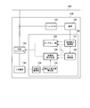
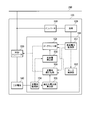
- FIG. 1 is a schematic block diagram showing a configuration of a vehicle 100 including a charge / discharge control device 150 according to the first embodiment of the present invention.
- the vehicle 100 according to the present embodiment includes an inverter 110, a load 120, a DCDC converter 130, a secondary battery 140, and a charge / discharge control device 150.
- the inverter 110 converts the DC power supplied from the overhead line 200 and the DC power supplied from the secondary battery 140 via the DCDC converter 130 into AC power.
- Load 120 causes vehicle 100 to be powered by AC power converted by inverter 110.
- the load 120 performs regenerative braking of the vehicle 100 and generates regenerative power.
- the regenerative power is supplied to the overhead line 200 and the secondary battery 140 via the inverter 110.
- the DCDC converter 130 converts the voltage of power supplied from the overhead line 200 and the load 120 and the voltage of power supplied from the secondary battery 140.
- the secondary battery 140 is connected to the overhead line 200 and the load 120 via the DCDC converter 130 and charges the power supplied from the underline 200 and the load 120. Further, the secondary battery 140 supplies power to the load 120 via the DCDC converter 130.
- the charge / discharge control device 150 is a device that controls charging / discharging of the secondary battery 140, and includes a load power monitoring unit 151, a mode control unit 152, a peak cut unit 153, a charge rate monitoring unit 154, and an optimized power value calculation unit. 155, a charge rate optimization unit 156 is provided.
- the load power monitoring unit 151 monitors the required power required for powering by the load 120 and the power value of regenerative power generated from the load 120.
- the required power and the regenerative power are collectively referred to as “load power”.
- the mode control unit 152 sets the control mode for controlling the charging / discharging of the secondary battery 140 based on the load power to the overhead line priority mode that prioritizes the power supply from the overhead line 200, or to optimize the charging rate of the secondary battery 140. Switch to one of the battery priority modes.
- the peak cut unit 153 charges and discharges the secondary battery 140 so that the power received from the overhead line 200 or the power transmitted to the overhead line 200 does not exceed a predetermined peak cut power.
- a power control instruction is output to the DCDC converter 130.
- the peak cut unit 153 generates power that is a difference between the required power and the received peak cut power that is the maximum value of power that can be received from the overhead line 200 when the vehicle 100 is powered. Outputs a discharge instruction to cause the battery to discharge.
- the peak cut unit 153 charges the secondary battery 140 with power that is the difference between the regenerative power and the power transmission peak cut power that is the maximum power that can be transmitted to the overhead line 200 when the vehicle 100 is braked. Output charging instructions.
- the charging rate monitoring unit 154 monitors the charging rate of the secondary battery 140.
- the charging rate can be monitored, for example, by measuring the open circuit voltage of the secondary battery 140 and specifying the charging rate corresponding to the open circuit voltage.
- the optimized power value calculation unit 155 calculates an optimized power value that is a power value for causing the charging rate of the secondary battery 140 to reach a predetermined target charging rate.
- the calculation of the optimized power value is performed by PI control. Note that the optimized power value increases as the difference between the charging rate of the secondary battery 140 and the target charging rate increases. Specifically, when the charging rate of the secondary battery 140 is higher than the target charging rate, the optimized power value (discharge optimized power value) used for discharging the secondary battery 140 is the target charging rate of the secondary battery 140.
- the optimized power value (charging optimized power value) used for charging the secondary battery 140 is such that the charging rate of the secondary battery 140 is higher than the target charging rate. It increases as it gets lower.
- the charging rate optimization unit 156 outputs, to the DCDC converter 130, a control instruction for the power charged / discharged by the secondary battery 140 based on the optimized power value.
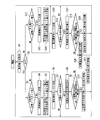
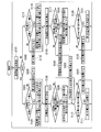
- FIG. 2 is a flowchart showing the operation of the charge / discharge control apparatus 150 according to the first embodiment of the present invention.
- the load power monitoring unit 151 acquires the load power (step S1).
- the load power monitoring unit 151 determines whether the operation of the load 120 is power running or regeneration (step S2).
- the mode control unit 152 determines whether or not the required power is larger than a preset received peak cut power. (Step S3). When it is determined that the required power is larger than the preset power receiving peak cut power (step S3: YES), the mode control unit 152 switches the control mode to the overhead line priority mode (step S4). In addition, when it is already in the overhead line priority mode, it is not necessary to perform switching.
- the peak cut unit 153 is a power value obtained by dividing the power value of the difference between the required power and the received peak cut power by the efficiency of the DCDC converter 130.
- a discharge instruction for instructing to discharge the secondary battery 140 is output to the DCDC converter 130 (step S5). Then, returning to step S1, the charge / discharge control device 150 performs charge / discharge control at the next time.
- step S3 determines in step S3 that the required power is equal to or lower than the preset power receiving peak cut power (step S3: NO)
- step S6 the mode control unit 152 switches the control mode to the battery priority mode (step S6). If the battery priority mode is already set, there is no need to perform switching.
- the charging rate monitoring unit 154 acquires the charging rate of the secondary battery 140.
- the optimized power value calculation unit 155 determines whether or not the charging rate of the secondary battery 140 is greater than a preset target charging rate (step S7).
- the charging rate of the secondary battery 140 is equal to or lower than the target charging rate (step S7: NO)
- the secondary battery 140 is discharged to move the charging rate of the secondary battery 140 away from the target charging rate.
- the secondary battery 140 is not discharged, and the process returns to step S1.
- optimized power value calculation unit 155 performs PI control based on the charging rate and target charging rate of secondary battery 140.
- a discharge appropriate power value is calculated (step S8).
- the charge rate optimization unit 156 determines whether or not the power value obtained by dividing the required power by the efficiency of the DCDC converter 130 is equal to or less than the discharge optimization power value (step S9).
- step S9 When it is determined that the power value obtained by dividing the required power by the efficiency of the DCDC converter 130 is equal to or less than the discharge appropriate power value (step S9: YES), the charging rate optimization unit 156 efficiently converts the required power.
- a discharge instruction for instructing to discharge the secondary battery 140 with the electric power value obtained by dividing is output to the DCDC converter 130 (step S10).
- the power required by the load 120 is covered by the secondary battery 140.
- the charging rate of the secondary battery 140 thereby approaches the target charging rate.
- the charge / discharge control device 150 performs charge / discharge control at the next time.
- step S9 when it is determined that the power value obtained by dividing the required power by the efficiency of the DCDC converter 130 is greater than the discharge appropriate power value (NO in step S9), the charge rate optimization unit 156 A discharge instruction for instructing the secondary battery 140 to be discharged by the value is output to the DCDC converter 130 (step S11). As a result, the charging rate of the secondary battery 140 approaches the target charging rate. At this time, similarly to step S10, if the secondary battery 140 is controlled to cover all power required by the load 120, the charging rate of the secondary battery 140 may be lower than the target charging rate.
- the secondary battery 140 is discharged with the discharge appropriate power value, and the remaining power is supplied from the overhead line 200, so that the charge / discharge is appropriately controlled so that the charge rate of the secondary battery 140 approaches the target charge rate. be able to. Then, returning to step S1, the charge / discharge control device 150 performs charge / discharge control at the next time.
- step S2 determines that the load power monitoring unit 151 is in regenerative braking.
- step S2 determines that the load 120 is in regenerative braking. It is determined whether or not (step S12).
- step S12 determines that the regenerative power is larger than the transmission peak cut power.
- step S13 the mode control unit 152 switches the control mode to the overhead line priority mode. In addition, when it is already in the overhead line priority mode, it is not necessary to perform switching.
- the peak cut unit 153 uses a power value obtained by multiplying the power value of the difference between the regenerative power and the transmission peak cut power by the efficiency of the DCDC converter 130.
- a charging instruction for instructing charging of the next battery 140 is output to the DCDC converter 130 (step S14). Then, returning to step S1, the charge / discharge control device 150 performs charge / discharge control at the next time.
- step S12 determines in step S12 that the regenerative power is equal to or lower than the preset transmission peak cut power (step S12: NO)
- step S15 the mode control unit 152 switches the control mode to the battery priority mode (step S15). If the battery priority mode is already set, there is no need to perform switching.
- the charging rate monitoring unit 154 acquires the charging rate of the secondary battery 140.
- the optimized power value calculation unit 155 determines whether or not the charging rate of the secondary battery 140 is smaller than the target charging rate (step S16).
- the charging rate of the secondary battery 140 is equal to or higher than the target charging rate (step S16: NO)
- charging the secondary battery 140 causes the charging rate of the secondary battery 140 to move away from the target charging rate. The next battery 140 is not charged, and the process returns to step S1.
- optimized power value calculation unit 155 performs PI control based on the charging rate and target charging rate of secondary battery 140.
- a charge appropriate power value is calculated (step S17).
- the charge rate optimization unit 156 determines whether or not the power value obtained by multiplying the regenerative power by the efficiency of the DCDC converter 130 is equal to or less than the charge optimization power value (step S18).
- step S18 When it is determined that the power value obtained by multiplying the regenerative power by the efficiency of the DCDC converter 130 is equal to or less than the charge appropriate power value (step S18: YES), the charging rate optimizing unit 156 multiplies the regenerative power by the efficiency.
- a charging instruction for instructing charging of the secondary battery 140 with the obtained power value is output to the DCDC converter 130 (step S19).
- the regenerative power generated by the load 120 is charged in the secondary battery 140.
- the charging rate of the secondary battery 140 thereby approaches the target charging rate.
- the charge / discharge control device 150 performs charge / discharge control at the next time.
- step S18 NO
- step S20 a charging instruction for instructing charging of the secondary battery 140 is output to the DCDC converter 130.
- the charging rate of the secondary battery 140 approaches the target charging rate.
- step S19 similarly to step S19, if the regenerative power generated by the load 120 is controlled to be charged in the secondary battery 140, the charge rate of the secondary battery 140 may exceed the target charge rate.
- the charge / discharge is appropriately controlled so that the charge rate of the secondary battery 140 approaches the target charge rate. be able to. Then, returning to step S1, the charge / discharge control device 150 performs charge / discharge control at the next time.
- step S1 to step S20 By repeatedly executing the processing from step S1 to step S20, the power supplied by the overhead line 200 and the power collected by the overhead line 200 are peak cut, and the charging rate of the secondary battery 140 is controlled to approach the target charging rate. can do.
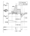
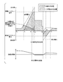
- FIG. 3 is a diagram illustrating a specific example of a state during charge / discharge control of the secondary battery 140 by the charge / discharge control device 150 according to the first embodiment of the present invention.
- the load power monitoring unit 151 acquires load power and determines that the operation of the load 120 is powering in step S2.
- the mode control unit 152 compares the required power of the load 120 with the received peak cut power.
- the required power of load 120 is smaller than the received peak cut power. Therefore, as shown in FIG. 3 (C), mode control unit 152 sets the control mode to the battery in step S 6. Switch to priority mode.
- the optimized power value calculation unit 155 determines whether or not the charging rate of the secondary battery 140 is greater than the target charging rate. At time t 0 , as shown in FIG. 3B, the charging rate of the secondary battery 140 is larger than the target charging rate, so that the optimized power value calculation unit 155 performs step S8 as shown in FIG. 3A. A discharge appropriate power value is calculated.
- step S9 the charging rate optimization unit 156 compares the power value obtained by dividing the required power by the efficiency of the DCDC converter 130 with the discharge optimization power value.
- the power value obtained by dividing the required power by the efficiency of the DCDC converter 130 is equal to or less than the discharge appropriate power value. Therefore, the charging rate optimization unit 156 outputs a discharge instruction for discharging the secondary battery 140 with a power value obtained by dividing the required power by the efficiency of the DCDC converter 130 in step S10.
- the charge rate optimization unit 156 outputs a discharge instruction for discharging the secondary battery 140 with the discharge appropriate power value in step S11. And the electric power of the difference of required electric power and the electric power which the secondary battery 140 supplies will be supplied to the load 120 from the overhead line 200 as shown to FIG. 3 (A).
- the mode control unit 152 switches the control mode to the overhead line priority mode in step S4.
- the peak cut unit 153 outputs a discharge instruction for discharging the secondary battery 140 at a power value obtained by dividing the difference between the required power and the received peak cut power by the efficiency of the DCDC converter 130.
- the power supplied from the overhead line 200 is the received peak cut power.
- step S6 the mode control unit 152 switches the control mode to the battery priority mode in step S6.
- step S7 the charge and discharge control device 150, it is determined in step S7, does not output the discharge instruction to the DCDC converter 130. Therefore, all the necessary power by the load 120 is provided from the overhead line 200.
- step S12 the mode control unit 152 compares the regenerative power of the load 120 with the power transmission peak cut power.
- the mode control unit 152 As shown in FIG. 3 (C), the control mode by step S13 Switch to overhead line priority mode.
- the peak cut unit 153 outputs a charge instruction for charging the secondary battery 140 with a power value obtained by multiplying the difference between the regenerative power and the transmission peak cut power by the efficiency of the DCDC converter 130. At this time, the electric power collected by the overhead line 200 becomes the transmission peak cut electric power. Further, the charging of the secondary battery 140 at time t 4, as shown in FIG. 3 (B), the charging rate of the secondary battery 140 is higher than the target charging rate.
- the mode control unit 152 switches the control mode to the battery priority mode in step S15.
- the charging rate of the secondary battery 140 is higher than the target charging rate. Therefore, the charge / discharge control device 150 does not output a charge instruction to the DCDC converter 130 based on the determination in step S16. Therefore, all the regenerative power of the load 120 is recovered to the overhead line 200.
- the charge rate optimization unit 156 compares the power value obtained by dividing the required power by the efficiency of the DCDC converter 130 with the discharge optimization power value in step S9.
- the power value obtained by dividing the required power efficiency of the DCDC converter 130 is less discharge optimized power values. Therefore, the charging rate optimization unit 156 outputs a discharge instruction for discharging the secondary battery 140 at a power value obtained by dividing the required power by the efficiency of the DCDC converter 130 in step S10. As a result, the charging rate of the secondary battery 140 again approaches the target charging rate.
- the charge / discharge control device 150 when the required power of the load 120 is equal to or higher than the received peak cut power, the charge / discharge control device 150 supplies the secondary battery 140 with power equal to or greater than the difference between the required power and the received peak cut power. When the required power is less than the received peak cut power, the secondary battery 140 is discharged with a power equal to or less than the discharge appropriate power value. Further, according to the present embodiment, when the regenerative power of the load 120 is greater than or equal to the transmission peak cut power, the charge / discharge control device 150 supplies power equal to or greater than the difference between the regenerative power and the transmission peak cut power to the secondary battery 140.
- the secondary battery 140 When the regenerative power is less than the transmission peak cut power, the secondary battery 140 is charged with power equal to or less than the charge optimization power value. Thereby, the charge rate of the secondary battery 140 can be adjusted while performing peak cut of the power transmitted to the overhead line 200 and the power received from the overhead line 200.
- the peak cut unit 153 controls charging / discharging of the secondary battery 140 so that the power supplied or recovered by the overhead line 200 becomes the peak cut power in the overhead line priority mode has been described.
- the secondary battery 140 allows the peak cut unit 153 to set the power transmitted and received by the overhead line 200 to be equal to or lower than the peak cut power. You may make it control charging / discharging of.
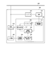
- FIG. 4 is a schematic block diagram illustrating a configuration of the vehicle 100 including the charge / discharge control device 150 according to the second embodiment of the present invention.
- the charge / discharge control device 150 according to the second embodiment includes a power determination unit 157 without the mode control unit 152 in the configuration of the charge / discharge control device 150 according to the first embodiment.
- the power determination unit 157 outputs an instruction to charge / discharge the secondary battery 140 with the larger power out of the power to charge / discharge the secondary battery 140 output from the peak cut unit 153 and the charge rate optimization unit 156. Output to the converter 130.
- FIG. 5 is a flowchart showing the operation of the charge / discharge control apparatus 150 according to the second embodiment of the present invention.
- the load power monitoring unit 151 acquires the load power (step S101).
- the load power monitoring unit 151 determines whether the operation of the load 120 is power running or regeneration (step S102).
- the peak cut unit 153 determines whether or not the required power is larger than the preset received peak cut power. (Step S103). When the peak cut unit 153 determines that the required power is larger than the preset received power peak cut power (step S103: YES), the peak cut unit 153 determines the power value of the difference between the required power and the received peak cut power as the efficiency of the DCDC converter 130. The power value obtained by dividing by is calculated as the first power value (step S104). On the other hand, when the peak cut unit 153 determines that the required power is equal to or less than the preset power receiving peak cut power (step S103: NO), the peak cut unit 153 sets the first power value to zero (step S105).
- the charge rate monitoring unit 154 acquires the charge rate of the secondary battery 140.
- the optimized power value calculation unit 155 calculates a discharge optimized power value by PI control based on the charging rate and the target charging rate of the secondary battery 140 (step S106). In addition, when the charging rate of the secondary battery 140 is lower than the target charging rate, the discharge appropriate power value is zero.
- the charge rate optimization unit 156 determines whether or not the power value obtained by dividing the required power by the efficiency of the DCDC converter 130 is equal to or less than the discharge optimization power value (step S107).
- step S107 When it is determined that the power value obtained by dividing the required power by the efficiency of the DCDC converter 130 is equal to or less than the discharge optimized power value (step S107: YES), the charging rate optimization unit 156 efficiently converts the required power.
- the power value obtained by dividing is calculated as the second power value (step S108).
- the charge rate optimization unit 156 The value is set as the second power value (step S109).
- step S110 When the charging rate optimization unit 156 calculates the second power value in step S108 or step S109, the power determination unit 157 calculates the first power value calculated by the peak cut unit 153, and the charging rate optimization unit 156 calculates it. It is determined whether or not it is greater than the second power value (step S110).
- step S110: YES When power determination unit 157 determines that the first power value is greater than the second power value (step S110: YES), power determination unit 157 issues a discharge instruction that instructs to discharge secondary battery 140 with the first power value. It outputs to the DCDC converter 130 (step S111).
- step S110 On the other hand, when determining that the first power value is equal to or lower than the second power value (step S110: NO), the power determination unit 157 instructs to discharge the secondary battery 140 with the second power value.
- a discharge instruction is output to the DCDC converter 130 (step S112). Then, returning to step S101, the charge / discharge control device 150 performs charge / discharge control at the next
- step S102 determines that the load power monitoring unit 151 determines in step S102 that the load 120 is under regenerative braking (step S102: NO)
- the peak cut unit 153 determines that the regenerative power is based on the transmission peak cut power set in advance. It is determined whether it is larger (step S113).
- step S113 determines that the regenerative power is larger than the preset transmission peak cut power (step S113: YES)
- the efficiency of the DCDC converter 130 is set to the power value of the difference between the regenerative power and the transmission peak cut power.
- the power value obtained by multiplying by is calculated as the first power value (step S114).
- step S113 determines that the regenerative power is equal to or lower than the preset transmission peak cut power (step S113: NO)
- the peak cut unit 153 sets the first power value to zero (step S115).
- the charging rate monitoring unit 154 acquires the charging rate of the secondary battery 140.
- the optimized power value calculation unit 155 calculates a charge optimized power value by PI control based on the charging rate and the target charging rate of the secondary battery 140 (step S116). In addition, when the charging rate of the secondary battery 140 is lower than the target charging rate, the charge appropriate power value is zero.
- the charge rate optimization unit 156 determines whether or not the power value obtained by multiplying the regenerative power by the efficiency of the DCDC converter 130 is equal to or less than the charge optimization power value (step S117).
- step S117: YES When it is determined that the power value obtained by multiplying the regenerative power by the efficiency of the DCDC converter 130 is equal to or less than the charge appropriate power value (step S117: YES), the charging rate optimization unit 156 multiplies the regenerative power by the efficiency. The power value obtained in this way is calculated as the second power value (step S118). On the other hand, when the charging rate optimization unit 156 determines that the power value obtained by multiplying the regenerative power by the efficiency of the DCDC converter 130 is larger than the charging optimization power value (step S117: NO), the charging optimization power value Is the second power value (step S119).
- step S118 When the charging rate optimization unit 156 calculates the second power value in step S118 or step S119, the power determination unit 157 calculates the first power value calculated by the peak cut unit 153, and the charging rate optimization unit 156 calculates the first power value. It is determined whether or not it is greater than the second power value (step S120).
- step S120 When power determination unit 157 determines that the first power value is greater than the second power value (step S120: YES), power determination unit 157 issues a charging instruction that instructs charging secondary battery 140 with the first power value. It outputs to the DCDC converter 130 (step S121).
- step S120 when determining that the first power value is equal to or lower than the second power value (step S120: NO), the power determining unit 157 instructs to charge the secondary battery 140 with the second power value.
- a charge instruction is output to the DCDC converter 130 (step S122). Then, returning to step S101, the charge / discharge control device 150 performs charge / discharge control at the next time.
- the power supplied by the overhead line 200 and the power collected by the overhead line 200 are peak cut, and control is performed so that the charging rate of the secondary battery 140 approaches the target charging rate. can do.
- the charging rate of the secondary battery 140 can be controlled to approach the target charging rate earlier than the configuration of the first embodiment.
- FIG. 6 is a diagram illustrating a specific state example during charge / discharge control of the secondary battery 140 by the charge / discharge control device 150 according to the second embodiment of the present invention.
- the load power monitoring unit 151 acquires load power and determines that the operation of the load 120 is power running in step S102.
- the peak cut unit 153 sets the first power value to zero in step S105.
- the peak cut unit 153 sets the first power value to zero in step S105.
- the charge rate optimization unit 156 performs the required power by step S108.
- a power value obtained by dividing the above by the efficiency of the DCDC converter 130 is defined as a second power value.
- the power determination unit 157 uses the second power, that is, the power value obtained by dividing the necessary power by the efficiency of the DCDC converter 130 to the secondary battery 140. Outputs a discharge instruction to discharge.
- the charge rate optimization unit 156 performs the discharge optimization by step S109.
- the power value is set as the second power value.
- the power determination unit 157 outputs a discharge instruction for discharging the secondary battery 140 with the second power, that is, the discharge appropriate power value. And the electric power of the difference of required electric power and the electric power which the secondary battery 140 supplies will be supplied to the load 120 from the overhead line 200 as shown to FIG. 6 (A).
- the difference for the necessary power of the load 120 is above the power receiving peak cut power, peak shaving unit 153, a required power and the power reception peak cut power in step S104
- the power value obtained by dividing the power value by the efficiency of the DCDC converter 130 is defined as a first power value.
- the charge rate optimization unit 156 performs the discharge optimization by step S109.
- the power value is set as the second power value.
- the power determination unit 157 outputs a discharge instruction for discharging the secondary battery 140 with the second power, that is, the discharge appropriate power value. That is, according to the present embodiment, even when the required power is equal to or higher than the received peak cut power, the discharge appropriate power value is equal to or higher than the difference between the required power and the received peak cut power.
- the secondary battery 140 is discharged at the generated power value.
- the power determination unit 157 since the first power value is greater than the second power value, the power determination unit 157, the power value of the difference between the first power, i.e., the required power and the power receiving peak cut power A discharge instruction for discharging the secondary battery 140 is output. At this time, the power supplied from the overhead line 200 is the received peak cut power.
- step S105 since the required power of the load 120 is smaller than the receiving peak cut power, peak shaving unit 153, a zero first power value in step S105 To do.
- FIG. 6 (B) in the charging rate of the secondary battery 140 is time t 4, since the below target charging rate, discharging optimized power value is zero. Therefore, since the power value obtained by dividing the required power by the efficiency of the DCDC converter 130 is larger than the discharge optimized power value, the charge rate optimization unit 156 sets the discharge optimized power value as the second power value in step S109. To do. That is, the second power value is zero.
- the power determination unit 157 outputs a discharge instruction for discharging the secondary battery 140 with a power value of zero. This is equivalent to not outputting a discharge instruction. Therefore, all the necessary power by the load 120 is provided from the overhead line 200.
- the load power monitor unit 151 obtains the load power
- the operation of the load 120 is regenerative braking by step S102.
- the peak cut unit 153 sets the power value of the difference between the regenerative power and the transmission peak cut power in step S114.
- the power value multiplied by the efficiency of the DCDC converter 130 is defined as the first power value.
- the charge rate optimization unit 156 performs charge optimization in step S119.
- the power value is set as the second power value.
- the power determination unit 157 sets the efficiency of the DCDC converter 130 to the first power, that is, the power value of the difference between the regenerative power and the transmission peak cut power.
- a charge instruction for charging the secondary battery 140 with the multiplied power value is output.
- the regenerative power of the load 120 is smaller than the receiving peak cut power, peak shaving unit 153, a zero first power value in step S115 To do.
- the charge rate optimization unit 156 sets the charge optimization power value as the second power value in step S119. To do. That is, the second power value is zero.
- the power determination unit 157 outputs a charging instruction for charging the secondary battery 140 with a power value of zero. This is equivalent to not outputting a charge instruction. Therefore, all the regenerative power of the load 120 is recovered to the overhead line 200.
- the operation of the load 120 starts to power running from regenerative braking.
- the peak cut unit 153 sets the first power value to zero in step S105.
- the charge rate optimization unit 156 performs the required power by step S108.
- a power value obtained by dividing the above by the efficiency of the DCDC converter 130 is defined as a second power value.
- the power determination unit 157 uses the second power, that is, the power value obtained by dividing the necessary power by the efficiency of the DCDC converter 130 to the secondary battery 140. Outputs a discharge instruction to discharge. As a result, the charging rate of the secondary battery 140 again approaches the target charging rate.
- the charge / discharge control device 150 when the required power is equal to or greater than the received peak cut power, the charge / discharge control device 150 has a discharge optimization power value equal to or greater than the difference between the required power and the received peak cut power. Then, the secondary battery 140 is made to discharge the electric power of the discharge appropriate power value. Moreover, according to this embodiment, when the regenerative power is equal to or higher than the transmission peak cut power, the charge / discharge control device 150 has a charge optimization power value equal to or higher than the difference between the regenerative power and the transmission peak cut power. Then, the secondary battery 140 is charged with the power of the charge appropriate power value.
- the charge rate of the secondary battery 140 can be adjusted more efficiently than the first embodiment while performing peak cuts of the power transmitted to the overhead line 200 and the power received from the overhead line 200. Further, since there is no determination of the control mode, the control logic is simpler than in the first embodiment. Furthermore, since a rapid power change in the secondary power can be suppressed as compared with the first embodiment, it is possible to reduce the burden on devices such as the DCDC converter 130 and the inverter 110.
- the present invention is not limited to this.
- the discharge optimization power value is equal to or greater than the power obtained by dividing the difference between the required power and the received peak cut power by the efficiency of the DCDC converter 130.
- the same effect can be acquired by outputting the instruction
- the control mode is the overhead line priority mode
- the peak cut unit 153 has a charge optimization power value equal to or higher than the power obtained by multiplying the difference between the required power and the received peak cut power by the efficiency of the DCDC converter 130.
- the same effect can be obtained by outputting a charge instruction for charging the secondary battery 140 with the charge appropriate power value.
- the charge / discharge control instruction by the peak cut unit 153 is the use of the secondary battery 140 in the charge / discharge control device 150 according to the first embodiment or the second embodiment. It is controlled so as to be within a voltage range or a working current range. That is, the discharge control instruction by the peak cut unit 153 controls the discharge at a power value less than the maximum discharge power value that the secondary battery 140 allows the discharge, and the charge control instruction by the peak cut unit 153 receives the secondary battery 140. Is controlled to control discharging at a power value lower than the maximum charging power value allowing charging.
- the power calculated by the peak cut unit 153 in step S5 or step S104 is the product of the monitor value of the voltage of the secondary battery 140 and the maximum allowable discharge current amount. To be less than the power value indicated by.
- the maximum allowable discharge current amount is a current obtained by dividing the open circuit voltage of the secondary battery 140 by the minimum allowable voltage of the secondary battery 140 and dividing by the internal resistance value of the secondary battery 140. A value may be used.
- the power calculated by the peak cut unit 153 in step S14 or step S114 is indicated by the product of the monitored value of the voltage of the secondary battery 140 and the minimum allowable discharge current amount. Try to be less than the power value.
- the minimum allowable discharge current amount is a current obtained by dividing the open circuit voltage of the secondary battery 140 by the maximum allowable voltage of the secondary battery 140 and dividing by the internal resistance value of the secondary battery 140. A value may be used.
- the charge / discharge control device 150 can perform charge / discharge control of the secondary battery 140 without departing from the usage range of the secondary battery 140. If the usage range is inevitably exceeded during operation of the vehicle 100, a power supply device (not shown) that supplies power to the overhead line 200 has a margin, or the acceleration or deceleration of the vehicle 100 is increased. By adjusting, it controls so that it does not deviate from the use range of the secondary battery 140.
- FIG. 7 is a schematic block diagram showing a configuration of the vehicle 100 including the charge / discharge control device 150 according to the fourth embodiment of the present invention.
- the charge / discharge control device 150 according to the fourth embodiment is further provided with a charge / discharge stop unit 158 (charge stop unit, discharge stop unit) in addition to the charge / discharge control device 150 according to the first embodiment.
- the charge / discharge stop unit 158 stops the discharge by the peak cut unit 153 when the charge rate of the secondary battery 140 is less than the minimum charge rate allowed for the secondary battery 140.
- the charge / discharge stopping unit 158 stops the charging by the peak cut unit 153.
- the charge / discharge control device 150 can perform charge / discharge control of the secondary battery 140 within a range not departing from the use range of the secondary battery 140.
- a power supply device (not shown) that supplies power to the overhead line 200 has a margin, or the acceleration or deceleration of the vehicle 100 is increased. By adjusting, it controls so that it does not deviate from the use range of the secondary battery 140.
- the charging rate optimization unit 156 does not output a charging instruction when the charging rate of the secondary battery 140 is higher than the target charging rate, and when the charging rate of the secondary battery 140 is lower than the target charging rate. Since the discharge instruction is not output, it is sufficient for the charge / discharge stop unit 158 to stop at least the charge / discharge instruction by the peak cut unit 153.
- the above-described charging / discharging control device 150 has a computer system inside.
- the operation of each processing unit described above is stored in a computer-readable recording medium in the form of a program, and the above processing is performed by the computer reading and executing this program.
- the computer-readable recording medium means a magnetic disk, a magneto-optical disk, a CD-ROM, a DVD-ROM, a semiconductor memory, or the like.
- the computer program may be distributed to the computer via a communication line, and the computer that has received the distribution may execute the program.
- the program may be for realizing a part of the above-described functions. Furthermore, what can implement
- the present invention can be applied to an overhead wire-less vehicle equipped with a secondary battery.
Landscapes
- Engineering & Computer Science (AREA)
- Power Engineering (AREA)
- Mechanical Engineering (AREA)
- Transportation (AREA)
- Chemical Kinetics & Catalysis (AREA)
- Manufacturing & Machinery (AREA)
- Chemical & Material Sciences (AREA)
- Electrochemistry (AREA)
- General Chemical & Material Sciences (AREA)
- Sustainable Energy (AREA)
- Sustainable Development (AREA)
- Life Sciences & Earth Sciences (AREA)
- Charge And Discharge Circuits For Batteries Or The Like (AREA)
- Secondary Cells (AREA)
- Electric Propulsion And Braking For Vehicles (AREA)
Priority Applications (5)
| Application Number | Priority Date | Filing Date | Title |
|---|---|---|---|
| CN201280056942.0A CN103947073B (zh) | 2011-12-09 | 2012-11-13 | 充放电控制装置、充电控制方法以及放电控制方法 |
| SG11201402648XA SG11201402648XA (en) | 2011-12-09 | 2012-11-13 | Charge and discharge control device, charge control method, discharge control method, and program |
| HK14111783.2A HK1198267B (en) | 2011-12-09 | 2012-11-13 | Charging and discharging control device, charging control method and discharging control method |
| IN1010MUN2014 IN2014MN01010A (enExample) | 2011-12-09 | 2012-11-13 | |
| US14/360,699 US9419461B2 (en) | 2011-12-09 | 2012-11-13 | Charge and discharge control device, charge control method, discharge control method, and program |
Applications Claiming Priority (2)
| Application Number | Priority Date | Filing Date | Title |
|---|---|---|---|
| JP2011-269937 | 2011-12-09 | ||
| JP2011269937A JP5615254B2 (ja) | 2011-12-09 | 2011-12-09 | 充放電制御装置、充電制御方法、放電制御方法、及びプログラム |
Publications (1)
| Publication Number | Publication Date |
|---|---|
| WO2013084673A1 true WO2013084673A1 (ja) | 2013-06-13 |
Family
ID=48574052
Family Applications (1)
| Application Number | Title | Priority Date | Filing Date |
|---|---|---|---|
| PCT/JP2012/079364 Ceased WO2013084673A1 (ja) | 2011-12-09 | 2012-11-13 | 充放電制御装置、充電制御方法、放電制御方法、及びプログラム |
Country Status (6)
| Country | Link |
|---|---|
| US (1) | US9419461B2 (enExample) |
| JP (1) | JP5615254B2 (enExample) |
| CN (1) | CN103947073B (enExample) |
| IN (1) | IN2014MN01010A (enExample) |
| SG (1) | SG11201402648XA (enExample) |
| WO (1) | WO2013084673A1 (enExample) |
Families Citing this family (11)
| Publication number | Priority date | Publication date | Assignee | Title |
|---|---|---|---|---|
| JP2524678Y2 (ja) | 1990-07-10 | 1997-02-05 | エムケー精工株式会社 | 高圧洗浄装置 |
| JPH0742471Y2 (ja) | 1990-07-24 | 1995-10-04 | 有限会社泉銅板 | パチンコ台洗浄機 |
| JP5901318B2 (ja) | 2012-02-02 | 2016-04-06 | 三菱重工業株式会社 | 充放電制御装置、充電制御方法、放電制御方法、及びプログラム |
| JP5931705B2 (ja) | 2012-11-28 | 2016-06-08 | 三菱重工業株式会社 | 充放電制御装置、充放電制御システム、充放電制御方法およびプログラム |
| JP6148927B2 (ja) * | 2013-08-05 | 2017-06-14 | 西日本旅客鉄道株式会社 | 電車駆動システム |
| JP6094469B2 (ja) * | 2013-12-25 | 2017-03-15 | トヨタ自動車株式会社 | 電源制御装置 |
| CN106660456B (zh) * | 2014-08-29 | 2019-06-14 | 株式会社东芝 | 铁路系统 |
| CN105398353B (zh) * | 2015-10-23 | 2019-01-08 | 惠州市亿能电子有限公司 | 一种轨道交通机车电源系统及其控制方法 |
| JP2018042392A (ja) * | 2016-09-08 | 2018-03-15 | 三菱自動車工業株式会社 | 車両用受電装置 |
| JP7304694B2 (ja) * | 2018-12-21 | 2023-07-07 | 株式会社日立製作所 | 電力需給調整システム、車載装置 |
| JP2021136816A (ja) * | 2020-02-28 | 2021-09-13 | セイコーエプソン株式会社 | 充放電制御装置および電子機器 |
Citations (2)
| Publication number | Priority date | Publication date | Assignee | Title |
|---|---|---|---|---|
| WO2011007695A1 (ja) * | 2009-07-15 | 2011-01-20 | 三菱電機株式会社 | 電気車の推進制御装置 |
| WO2011135631A1 (ja) * | 2010-04-30 | 2011-11-03 | パナソニック株式会社 | 満充電容量補正回路、充電システム、電池パック、及び満充電容量補正方法 |
Family Cites Families (13)
| Publication number | Priority date | Publication date | Assignee | Title |
|---|---|---|---|---|
| US5264764A (en) * | 1992-12-21 | 1993-11-23 | Ford Motor Company | Method for controlling the operation of a range extender for a hybrid electric vehicle |
| JP3050073B2 (ja) * | 1994-12-22 | 2000-06-05 | トヨタ自動車株式会社 | ハイブリッド電気自動車用発電制御装置 |
| US5592095A (en) * | 1995-08-28 | 1997-01-07 | Motorola, Inc. | Charge measurement circuit for a battery in which oscillators are used to indicate mode of operation |
| JP2000341861A (ja) * | 1999-05-24 | 2000-12-08 | Nissin Electric Co Ltd | 電力貯蔵システムの制御方法 |
| JP3832237B2 (ja) * | 2000-09-22 | 2006-10-11 | 日産自動車株式会社 | ハイブリッド車の制御装置 |
| JP3624831B2 (ja) * | 2000-12-28 | 2005-03-02 | 株式会社デンソー | 車両用電源装置及びエンジン駆動規制支援装置 |
| JP3596468B2 (ja) * | 2001-01-04 | 2004-12-02 | 日産自動車株式会社 | 燃料電池車両の制御装置 |
| JP2004079316A (ja) * | 2002-08-15 | 2004-03-11 | Nisshinbo Ind Inc | 急速充電電池用充電システム |
| JP4220946B2 (ja) | 2004-08-11 | 2009-02-04 | 三菱重工業株式会社 | 電気車両、架線レス交通システム及び架線レス交通システムの制御方法 |
| JP2007083989A (ja) * | 2005-09-26 | 2007-04-05 | Toshiba Corp | 電気鉄道交流き電システム |
| JP4166216B2 (ja) | 2004-12-22 | 2008-10-15 | 株式会社東芝 | 電気鉄道交流き電システム |
| JP2009273198A (ja) | 2008-04-30 | 2009-11-19 | Kawasaki Heavy Ind Ltd | 電池駆動車両のパワーフロー制御方法および制御装置 |
| US9030048B2 (en) * | 2010-10-18 | 2015-05-12 | Alpha Technologies Inc. | Uninterruptible power supply systems and methods for communications systems |
-
2011
- 2011-12-09 JP JP2011269937A patent/JP5615254B2/ja active Active
-
2012
- 2012-11-13 CN CN201280056942.0A patent/CN103947073B/zh active Active
- 2012-11-13 IN IN1010MUN2014 patent/IN2014MN01010A/en unknown
- 2012-11-13 SG SG11201402648XA patent/SG11201402648XA/en unknown
- 2012-11-13 US US14/360,699 patent/US9419461B2/en active Active
- 2012-11-13 WO PCT/JP2012/079364 patent/WO2013084673A1/ja not_active Ceased
Patent Citations (2)
| Publication number | Priority date | Publication date | Assignee | Title |
|---|---|---|---|---|
| WO2011007695A1 (ja) * | 2009-07-15 | 2011-01-20 | 三菱電機株式会社 | 電気車の推進制御装置 |
| WO2011135631A1 (ja) * | 2010-04-30 | 2011-11-03 | パナソニック株式会社 | 満充電容量補正回路、充電システム、電池パック、及び満充電容量補正方法 |
Also Published As
| Publication number | Publication date |
|---|---|
| JP2013123280A (ja) | 2013-06-20 |
| IN2014MN01010A (enExample) | 2015-07-03 |
| JP5615254B2 (ja) | 2014-10-29 |
| CN103947073B (zh) | 2016-10-12 |
| HK1198267A1 (en) | 2015-03-20 |
| US20150180242A1 (en) | 2015-06-25 |
| US9419461B2 (en) | 2016-08-16 |
| CN103947073A (zh) | 2014-07-23 |
| SG11201402648XA (en) | 2014-10-30 |
Similar Documents
| Publication | Publication Date | Title |
|---|---|---|
| JP5615254B2 (ja) | 充放電制御装置、充電制御方法、放電制御方法、及びプログラム | |
| CN105848978B (zh) | 控制系统、车辆用电源装置 | |
| EP2326586B1 (en) | Management of power from multiple sources in an elevator power system | |
| US9738173B2 (en) | Charging and discharging control device, charging and discharging control method, program and vehicle traffic system | |
| US9731619B2 (en) | Vehicle and control method for vehicle | |
| JP6284921B2 (ja) | 電力供給システム及び輸送機器、並びに、電力伝送方法 | |
| US9434273B2 (en) | Electrical source control apparatus | |
| KR20120037997A (ko) | 전기차 추진용 전력 변환 장치 | |
| JP2010273428A (ja) | 車両用駆動電源装置 | |
| JP2014107984A5 (enExample) | ||
| JP2012011896A (ja) | ハイブリッドカーの電源装置 | |
| JP2011166962A (ja) | 車両システム | |
| JPWO2013180171A1 (ja) | 充電システム、充電システムの制御方法、及び制御プログラム | |
| JP2014103831A (ja) | 電力貯蔵システムの制御装置及び方法並びにプログラム、それを備えた電力貯蔵システム | |
| JP7252807B2 (ja) | 電源システム | |
| JP5935300B2 (ja) | 電力供給装置及び充放電制御方法 | |
| JP2009183078A (ja) | 電気車の駆動システム | |
| JP5604984B2 (ja) | 電気鉄道システムのき電電圧制御方法 | |
| JP5404712B2 (ja) | 充電装置、車載用充電装置、車載用充電装置における充電方法 | |
| JP5366667B2 (ja) | 列車総括制御システム | |
| US9694704B2 (en) | Electrical charging/discharging controller, charging control method, discharging control method, and program | |
| JP5935301B2 (ja) | 電力供給装置及び供給電力制御方法 | |
| JP6195320B2 (ja) | 蓄電装置の充放電制御システム | |
| HK1198267B (en) | Charging and discharging control device, charging control method and discharging control method | |
| JP2013243869A (ja) | 二次電池の制御装置 |
Legal Events
| Date | Code | Title | Description |
|---|---|---|---|
| 121 | Ep: the epo has been informed by wipo that ep was designated in this application |
Ref document number: 12855515 Country of ref document: EP Kind code of ref document: A1 |
|
| WWE | Wipo information: entry into national phase |
Ref document number: 14360699 Country of ref document: US |
|
| NENP | Non-entry into the national phase |
Ref country code: DE |
|
| 122 | Ep: pct application non-entry in european phase |
Ref document number: 12855515 Country of ref document: EP Kind code of ref document: A1 |