WO2013084402A1 - 硫化水素分離方法および装置並びにこれを用いた水素製造システム - Google Patents
硫化水素分離方法および装置並びにこれを用いた水素製造システム Download PDFInfo
- Publication number
- WO2013084402A1 WO2013084402A1 PCT/JP2012/006928 JP2012006928W WO2013084402A1 WO 2013084402 A1 WO2013084402 A1 WO 2013084402A1 JP 2012006928 W JP2012006928 W JP 2012006928W WO 2013084402 A1 WO2013084402 A1 WO 2013084402A1
- Authority
- WO
- WIPO (PCT)
- Prior art keywords
- hydrogen sulfide
- carbon dioxide
- hydrogen
- gas
- adsorbent
- Prior art date
Links
Images

Classifications
-
- C—CHEMISTRY; METALLURGY
- C01—INORGANIC CHEMISTRY
- C01B—NON-METALLIC ELEMENTS; COMPOUNDS THEREOF; METALLOIDS OR COMPOUNDS THEREOF NOT COVERED BY SUBCLASS C01C
- C01B3/00—Hydrogen; Gaseous mixtures containing hydrogen; Separation of hydrogen from mixtures containing it; Purification of hydrogen
- C01B3/50—Separation of hydrogen or hydrogen containing gases from gaseous mixtures, e.g. purification
- C01B3/508—Separation of hydrogen or hydrogen containing gases from gaseous mixtures, e.g. purification by selective and reversible uptake by an appropriate medium, i.e. the uptake being based on physical or chemical sorption phenomena or on reversible chemical reactions
-
- B—PERFORMING OPERATIONS; TRANSPORTING
- B01—PHYSICAL OR CHEMICAL PROCESSES OR APPARATUS IN GENERAL
- B01D—SEPARATION
- B01D53/00—Separation of gases or vapours; Recovering vapours of volatile solvents from gases; Chemical or biological purification of waste gases, e.g. engine exhaust gases, smoke, fumes, flue gases, aerosols
- B01D53/02—Separation of gases or vapours; Recovering vapours of volatile solvents from gases; Chemical or biological purification of waste gases, e.g. engine exhaust gases, smoke, fumes, flue gases, aerosols by adsorption, e.g. preparative gas chromatography
- B01D53/04—Separation of gases or vapours; Recovering vapours of volatile solvents from gases; Chemical or biological purification of waste gases, e.g. engine exhaust gases, smoke, fumes, flue gases, aerosols by adsorption, e.g. preparative gas chromatography with stationary adsorbents
- B01D53/0462—Temperature swing adsorption
-
- B—PERFORMING OPERATIONS; TRANSPORTING
- B01—PHYSICAL OR CHEMICAL PROCESSES OR APPARATUS IN GENERAL
- B01D—SEPARATION
- B01D53/00—Separation of gases or vapours; Recovering vapours of volatile solvents from gases; Chemical or biological purification of waste gases, e.g. engine exhaust gases, smoke, fumes, flue gases, aerosols
- B01D53/34—Chemical or biological purification of waste gases
- B01D53/46—Removing components of defined structure
- B01D53/48—Sulfur compounds
- B01D53/52—Hydrogen sulfide
-
- B—PERFORMING OPERATIONS; TRANSPORTING
- B01—PHYSICAL OR CHEMICAL PROCESSES OR APPARATUS IN GENERAL
- B01D—SEPARATION
- B01D53/00—Separation of gases or vapours; Recovering vapours of volatile solvents from gases; Chemical or biological purification of waste gases, e.g. engine exhaust gases, smoke, fumes, flue gases, aerosols
- B01D53/34—Chemical or biological purification of waste gases
- B01D53/74—General processes for purification of waste gases; Apparatus or devices specially adapted therefor
- B01D53/81—Solid phase processes
- B01D53/82—Solid phase processes with stationary reactants
-
- C—CHEMISTRY; METALLURGY
- C01—INORGANIC CHEMISTRY
- C01B—NON-METALLIC ELEMENTS; COMPOUNDS THEREOF; METALLOIDS OR COMPOUNDS THEREOF NOT COVERED BY SUBCLASS C01C
- C01B17/00—Sulfur; Compounds thereof
- C01B17/16—Hydrogen sulfides
- C01B17/167—Separation
-
- C—CHEMISTRY; METALLURGY
- C01—INORGANIC CHEMISTRY
- C01B—NON-METALLIC ELEMENTS; COMPOUNDS THEREOF; METALLOIDS OR COMPOUNDS THEREOF NOT COVERED BY SUBCLASS C01C
- C01B3/00—Hydrogen; Gaseous mixtures containing hydrogen; Separation of hydrogen from mixtures containing it; Purification of hydrogen
- C01B3/50—Separation of hydrogen or hydrogen containing gases from gaseous mixtures, e.g. purification
- C01B3/56—Separation of hydrogen or hydrogen containing gases from gaseous mixtures, e.g. purification by contacting with solids; Regeneration of used solids
-
- C—CHEMISTRY; METALLURGY
- C01—INORGANIC CHEMISTRY
- C01B—NON-METALLIC ELEMENTS; COMPOUNDS THEREOF; METALLOIDS OR COMPOUNDS THEREOF NOT COVERED BY SUBCLASS C01C
- C01B32/00—Carbon; Compounds thereof
- C01B32/50—Carbon dioxide
-
- B—PERFORMING OPERATIONS; TRANSPORTING
- B01—PHYSICAL OR CHEMICAL PROCESSES OR APPARATUS IN GENERAL
- B01D—SEPARATION
- B01D2252/00—Absorbents, i.e. solvents and liquid materials for gas absorption
- B01D2252/20—Organic absorbents
- B01D2252/204—Amines
- B01D2252/20431—Tertiary amines
-
- B—PERFORMING OPERATIONS; TRANSPORTING
- B01—PHYSICAL OR CHEMICAL PROCESSES OR APPARATUS IN GENERAL
- B01D—SEPARATION
- B01D2253/00—Adsorbents used in seperation treatment of gases and vapours
- B01D2253/20—Organic adsorbents
-
- B—PERFORMING OPERATIONS; TRANSPORTING
- B01—PHYSICAL OR CHEMICAL PROCESSES OR APPARATUS IN GENERAL
- B01D—SEPARATION
- B01D2253/00—Adsorbents used in seperation treatment of gases and vapours
- B01D2253/25—Coated, impregnated or composite adsorbents
-
- B—PERFORMING OPERATIONS; TRANSPORTING
- B01—PHYSICAL OR CHEMICAL PROCESSES OR APPARATUS IN GENERAL
- B01D—SEPARATION
- B01D2256/00—Main component in the product gas stream after treatment
- B01D2256/16—Hydrogen
-
- B—PERFORMING OPERATIONS; TRANSPORTING
- B01—PHYSICAL OR CHEMICAL PROCESSES OR APPARATUS IN GENERAL
- B01D—SEPARATION
- B01D2257/00—Components to be removed
- B01D2257/30—Sulfur compounds
- B01D2257/304—Hydrogen sulfide
-
- B—PERFORMING OPERATIONS; TRANSPORTING
- B01—PHYSICAL OR CHEMICAL PROCESSES OR APPARATUS IN GENERAL
- B01D—SEPARATION
- B01D2257/00—Components to be removed
- B01D2257/50—Carbon oxides
- B01D2257/504—Carbon dioxide
-
- B—PERFORMING OPERATIONS; TRANSPORTING
- B01—PHYSICAL OR CHEMICAL PROCESSES OR APPARATUS IN GENERAL
- B01J—CHEMICAL OR PHYSICAL PROCESSES, e.g. CATALYSIS OR COLLOID CHEMISTRY; THEIR RELEVANT APPARATUS
- B01J2219/00—Chemical, physical or physico-chemical processes in general; Their relevant apparatus
-
- C—CHEMISTRY; METALLURGY
- C01—INORGANIC CHEMISTRY
- C01B—NON-METALLIC ELEMENTS; COMPOUNDS THEREOF; METALLOIDS OR COMPOUNDS THEREOF NOT COVERED BY SUBCLASS C01C
- C01B2203/00—Integrated processes for the production of hydrogen or synthesis gas
- C01B2203/04—Integrated processes for the production of hydrogen or synthesis gas containing a purification step for the hydrogen or the synthesis gas
- C01B2203/042—Purification by adsorption on solids
- C01B2203/043—Regenerative adsorption process in two or more beds, one for adsorption, the other for regeneration
-
- C—CHEMISTRY; METALLURGY
- C01—INORGANIC CHEMISTRY
- C01B—NON-METALLIC ELEMENTS; COMPOUNDS THEREOF; METALLOIDS OR COMPOUNDS THEREOF NOT COVERED BY SUBCLASS C01C
- C01B2203/00—Integrated processes for the production of hydrogen or synthesis gas
- C01B2203/04—Integrated processes for the production of hydrogen or synthesis gas containing a purification step for the hydrogen or the synthesis gas
- C01B2203/0465—Composition of the impurity
- C01B2203/0475—Composition of the impurity the impurity being carbon dioxide
-
- C—CHEMISTRY; METALLURGY
- C01—INORGANIC CHEMISTRY
- C01B—NON-METALLIC ELEMENTS; COMPOUNDS THEREOF; METALLOIDS OR COMPOUNDS THEREOF NOT COVERED BY SUBCLASS C01C
- C01B2203/00—Integrated processes for the production of hydrogen or synthesis gas
- C01B2203/04—Integrated processes for the production of hydrogen or synthesis gas containing a purification step for the hydrogen or the synthesis gas
- C01B2203/0465—Composition of the impurity
- C01B2203/0485—Composition of the impurity the impurity being a sulfur compound
-
- C—CHEMISTRY; METALLURGY
- C01—INORGANIC CHEMISTRY
- C01B—NON-METALLIC ELEMENTS; COMPOUNDS THEREOF; METALLOIDS OR COMPOUNDS THEREOF NOT COVERED BY SUBCLASS C01C
- C01B2203/00—Integrated processes for the production of hydrogen or synthesis gas
- C01B2203/14—Details of the flowsheet
- C01B2203/146—At least two purification steps in series
- C01B2203/147—Three or more purification steps in series
-
- Y—GENERAL TAGGING OF NEW TECHNOLOGICAL DEVELOPMENTS; GENERAL TAGGING OF CROSS-SECTIONAL TECHNOLOGIES SPANNING OVER SEVERAL SECTIONS OF THE IPC; TECHNICAL SUBJECTS COVERED BY FORMER USPC CROSS-REFERENCE ART COLLECTIONS [XRACs] AND DIGESTS
- Y02—TECHNOLOGIES OR APPLICATIONS FOR MITIGATION OR ADAPTATION AGAINST CLIMATE CHANGE
- Y02C—CAPTURE, STORAGE, SEQUESTRATION OR DISPOSAL OF GREENHOUSE GASES [GHG]
- Y02C20/00—Capture or disposal of greenhouse gases
- Y02C20/40—Capture or disposal of greenhouse gases of CO2
Definitions
- the present invention relates to a hydrogen sulfide separation method and apparatus and a hydrogen production system using the same, and more particularly, a hydrogen sulfide separation method capable of selectively separating hydrogen sulfide from a gas to be treated containing hydrogen sulfide and carbon dioxide. And a hydrogen production system using the hydrogen sulfide separation device.
- a synthesis gas obtained by partially burning coal or the like as a raw material in a high-temperature gasification furnace is produced, and hydrogen is separated from this synthesis gas .
- This synthesis gas contains hydrogen sulfide (H 2 S) in addition to hydrogen (H 2 ), carbon monoxide (CO), carbon dioxide (CO 2 ), and water (H 2 O) as main components.
- hydrogen sulfide is separated along with carbon dioxide, which is an acid gas, by chemical absorption (for example, absorption using an amine) or physical absorption (for example, absorption using a polymer solution). Yes.
- Patent Document 1 In order to separate hydrogen sulfide contained in carbon dioxide, a technology for selectively separating hydrogen sulfide using a triethanolamine aqueous solution has been developed (Patent Document 1). However, in this technique, most of the supplied carbon dioxide is absorbed in the triethanolamine aqueous solution together with hydrogen sulfide, so that it is insufficient in terms of a reduction in the amount of carbon dioxide recovered and an increase in the amount of heat of hydrogen sulfide separation.
- Patent Document 2 a technique for selectively separating hydrogen sulfide using an aqueous solution of a sterically hindered amine.
- This technology is an invention made to improve the reduction in the amount of hydrogen sulfide absorbed due to the large concentration difference between carbon dioxide and hydrogen sulfide, and is capable of selectively absorbing hydrogen sulfide. It is shown.
- carbon dioxide is absorbed simultaneously with hydrogen sulfide. Therefore, it is insufficient in terms of mixing hydrogen sulfide into the recovered carbon dioxide, increasing the amount of heat of hydrogen sulfide separation, and reducing the amount of carbon dioxide recovered.
- Patent Document 3 an attempt has been made to remove hydrogen sulfide by bringing a biogas containing carbon dioxide and hydrogen sulfide into contact with zeolite preliminarily adsorbed with water as a catalytic reaction inhibitor.
- the amount of water contained in the zeolite must be maintained at 0.2 to 3.3% by weight, and a high temperature of 200 ° C. or higher is required as a condition for desorbing hydrogen sulfide.
- problems remain in terms of difficulty in controlling moisture and large consumption of regenerative energy.
- the concentration of carbon dioxide in the synthesis gas is as high as 30% or more, whereas the concentration of hydrogen sulfide is as low as 1000 ppm or less, and the concentration difference is quite large.
- carbon dioxide and hydrogen sulfide are absorbed in proportion to the concentration difference (partial pressure). It is difficult to selectively absorb and separate low concentration hydrogen sulfide.
- the physical absorption method using a polymer solution it is possible to separate hydrogen sulfide with high efficiency by, for example, multistage absorption in which hydrogen sulfide is removed stepwise by changing the pressure. Compared to the energy required for separation. Further, even by multistage absorption, it is virtually impossible to make the concentration of hydrogen sulfide in the recovered carbon dioxide below the allowable limit.
- the present invention solves the above-described problems of the prior art in a hydrogen sulfide separator and a hydrogen production system, and an object of the present invention is to selectively select only hydrogen sulfide from a gas to be treated containing carbon dioxide and hydrogen sulfide. It is to provide a hydrogen sulfide separation method and apparatus that can be separated, and to provide a hydrogen production system using such a hydrogen sulfide separation method and apparatus.
- the hydrogen sulfide separation method of the present invention is an adsorption method in which hydrogen sulfide is selectively adsorbed by bringing a treatment gas containing hydrogen sulfide and carbon dioxide into contact with a hydrogen sulfide adsorbent in which an amine compound is supported on a porous material. And a desorption process of desorbing hydrogen sulfide by heating the adsorbed hydrogen sulfide adsorbent, wherein the amine compound is a tertiary amine, The contact between the hydrogen sulfide adsorbent and the gas to be treated is performed in a dry state, whereby only hydrogen sulfide is selectively separated.
- carbon dioxide When water is present, carbon dioxide is considered to be adsorbed by forming tertiary amine and alkylammonium ions supported on the porous material of the hydrogen sulfide adsorbent as shown below.
- R in the above formulas (1) and (2) represents a substituent.
- the reaction (1) since the contact between the hydrogen sulfide adsorbent and the gas to be processed is performed in a dry state, the reaction (1) does not occur, and only hydrogen sulfide is selectively adsorbed by the reaction (2). It is thought that it is adsorbed by the material.
- the tertiary amine in the present invention is preferably a tertiary alkanolamine. This is because tertiary alkanolamines are substantially odorless because of their low vapor pressure, and because they are water-soluble, they are easy to handle when carried on a porous material.
- the hydrogen sulfide separation device of the present invention uses a hydrogen sulfide adsorbent in which an amine compound is supported on a porous material, and selectively separates hydrogen sulfide from a gas to be treated containing hydrogen sulfide and carbon dioxide.
- An apparatus comprising an adsorbent packed tower filled with the hydrogen sulfide adsorbent, and an air supply for contacting the hydrogen sulfide adsorbent and the gas to be treated by supplying the gas to be treated to the adsorbent packed tower.
- a heated air flow supply means for supplying a heated air flow for desorbing hydrogen sulfide from the hydrogen sulfide adsorbent after adsorbing hydrogen sulfide to the adsorbent packed tower, wherein the amine compound is a tertiary amine.
- the contact between the hydrogen sulfide adsorbent and the gas to be treated in the adsorbent packed tower is performed in a dry state.
- reaction (1) is suppressed and only hydrogen sulfide is selectively adsorbed on the hydrogen sulfide adsorbent by the reaction (2).
- a hydrogen sulfide separation device uses a hydrogen sulfide adsorbent in which an amine compound is supported on a porous substance, and selectively selects hydrogen sulfide from a gas to be treated containing hydrogen sulfide and carbon dioxide.
- a hydrogen sulfide separation device that separates into a plurality of adsorbents, a plurality of adsorbent packed towers filled with the hydrogen sulfide adsorbent, and the gas to be treated supplied to the adsorbent packed towers, respectively, And a plurality of air supply means for bringing the gas to be treated into contact with each other, and a plurality of supply air flows to each of the adsorbent packed towers for heating and desorbing hydrogen sulfide from the hydrogen sulfide adsorbent after adsorbing hydrogen sulfide And the amine compound is a tertiary amine, and the contact between the hydrogen sulfide adsorbent and the gas to be treated in each of the adsorbent packed towers is performed in a dry state,
- the gas to be treated is supplied to a part of the plurality of adsorbent packed towers from the air supply means to selectively adsorb hydrogen sul
- the adsorbent packed column for selective adsorption of hydrogen sulfide and the adsorbent packed column for desorption of hydrogen sulfide can operate simultaneously, so that hydrogen sulfide can be separated continuously. It is possible.
- a tertiary alkanolamine is preferable as the tertiary amine because it is easy to handle.
- the hydrogen production system of the present invention is a hydrogen production system for producing hydrogen from a raw material gas containing hydrogen sulfide, carbon dioxide, and hydrogen, and producing hydrogen from the raw material gas.
- the hydrogen sulfide separator and the carbon dioxide separator are arranged on a high-pressure gas treatment line. Since the adsorption of hydrogen sulfide is performed under high pressure, the amount of hydrogen sulfide recovered per unit weight of the hydrogen sulfide adsorbent becomes larger than that at normal pressure, and the amount of hydrogen sulfide adsorbent can be reduced. It is to become.
- a hydrogen production system is a hydrogen production system for producing hydrogen from a raw material gas containing a raw material gas containing hydrogen sulfide, carbon dioxide and hydrogen, A carbon dioxide separator for separating hydrogen sulfide and carbon dioxide from the raw material gas, a hydrogen purifier for separating hydrogen from a gas provided downstream of the carbon dioxide separator and from which hydrogen sulfide and carbon dioxide have been removed, and carbon dioxide
- the hydrogen sulfide separation device according to any one of claims 3 to 5, wherein hydrogen sulfide is selectively separated from a gas containing hydrogen sulfide and carbon dioxide, which is provided downstream of the separation device and separated in the carbon dioxide separation device. It is provided with.
- hydrogen sulfide and carbon dioxide are first separated from the raw material gas, hydrogen is further separated from the gas from which hydrogen sulfide and carbon dioxide are separated, and hydrogen sulfide is selected from the gas containing hydrogen sulfide and carbon dioxide. Separated. Also in this hydrogen production system, since the hydrogen sulfide separation device is used, hydrogen sulfide can be separated from the mixed waste gas containing high-concentration carbon dioxide.
- the carbon dioxide separator is preferably disposed on the high-pressure gas treatment line, and the hydrogen sulfide separator is preferably disposed on the atmospheric pressure gas treatment line. This is because the hydrogen sulfide separation device separates hydrogen sulfide at normal temperature and normal pressure, so that it is not necessary to design the hydrogen sulfide separation device to a high pressure specification, and the system can be reduced in cost and size.
- a carbon dioxide separator that separates carbon dioxide using a carbon dioxide adsorbent in which an amine compound is supported on a porous material can be used.
- it is configured to generate a heated air flow for desorbing hydrogen sulfide from the hydrogen sulfide adsorbent in the hydrogen sulfide separator using the combustible off gas after separating hydrogen in the hydrogen purifier. Is possible.
- a carbon dioxide recovery device for recovering the finally separated carbon dioxide may be provided.
- the hydrogen production system of the present invention includes the above-described hydrogen sulfide separation device, only hydrogen sulfide can be selectively separated, and hydrogen and carbon dioxide having a very low hydrogen sulfide content can be obtained.
- FIG. 1 is a graph showing adsorption characteristic data indicating that hydrogen sulfide can be selectively separated by the hydrogen sulfide separation method of the present invention.
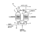
- FIG. 2 is a conceptual diagram of a hydrogen sulfide separation device according to an embodiment of the present invention.
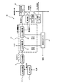
- FIG. 3 is a conceptual diagram of a hydrogen production system according to an embodiment of the present invention.
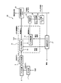
- FIG. 4 is a conceptual diagram of a hydrogen production system according to another embodiment of the present invention.
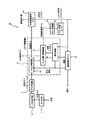
- FIG. 5 is a conceptual diagram of a hydrogen production system according to still another embodiment of the present invention.
- the hydrogen sulfide adsorbent used in the present invention can be prepared by loading a porous material with a tertiary amine in which contact between the hydrogen sulfide adsorbent and the gas to be treated is performed in a dry state.
- the porous material that can be used for preparing the hydrogen sulfide adsorbent include activated carbon and activated alumina.
- activated carbon is suitably used as the porous material.
- tertiary amine a tertiary alkanolamine is preferably used.
- triethanolamine N-methyl-diethanolamine, N, N-dimethyl-monoethanolamine, triisopropanolamine, N-methyl-diisopropanol
- examples thereof include amines and N, N-dimethyl-monoisopropanolamine, and among these, triethanolamine is preferably used.
- triethanolamine is used as the tertiary amine.
- the loading of the amine compound on the activated carbon can be obtained by putting the activated carbon into a triethanolamine aqueous solution prepared to a predetermined concentration, filtering and sufficiently drying.
- the carbon dioxide adsorbent used in the present invention can be prepared by supporting an amine compound on a porous substance.
- the porous substance that can be used for the preparation of the carbon dioxide adsorbent include activated carbon and activated alumina.
- activated carbon is used as the porous material.
- amine compounds include polyethyleneimine, monoethanolamine, diethanolamine, triethanolamine, tetraethylenepentamine, methyldiethanolamine, isopropanolamine, diisopropanolamine, dibutylamine, diethylenetriamine, triethylenetetramine, hexaethylenediamine, benzylamine, and morpholine. Is mentioned.
- diethanolamine is used.
- the loading of the amine compound on the activated carbon can be obtained by putting activated carbon into a diethanolamine aqueous solution adjusted to a predetermined concentration, filtering and drying.
- the carbon dioxide absorption method usable in the present invention is not limited to the adsorption method using the carbon dioxide adsorbent described above, and may be a chemical absorption method using an amine absorption liquid or a physical absorption method using an alcohol solvent. good.
- the concentration of carbon dioxide hardly changes from the start of the test, and shows almost the same value as the concentration of carbon dioxide set in the gas to be treated. Is not detected until about 2.5 hours have elapsed from the start of the test, and thereafter the concentration gradually increases to a value almost the same as the concentration of hydrogen sulfide set in the gas to be treated. This result indicates that the hydrogen sulfide adsorbent does not adsorb carbon dioxide at all, whereas hydrogen sulfide adsorbs almost completely until the adsorption amount reaches saturation.
- FIG. 2 shows a schematic configuration of the hydrogen sulfide separation device 10 according to one embodiment of the present invention.
- the hydrogen sulfide separation device 10 of the present embodiment includes two adsorbent packed columns 11 and 21 filled with hydrogen sulfide adsorbents for performing adsorption and desorption of hydrogen sulfide, respectively.
- triethanolamine is supported on a porous material such as activated carbon and used as a hydrogen sulfide adsorbent.
- a gas to be treated at about 40 ° C. containing carbon dioxide and hydrogen sulfide is supplied to the adsorbent packed columns 11 and 21 via a line 28.
- As the gas to be treated for example, a mixed gas obtained by treating a synthesis gas generated in a hydrogen production process, or carbon dioxide containing hydrogen sulfide separated from the mixed gas is supplied.
- a valve 12 that opens and closes the supply of the gas to be treated is provided between the line 28 and one of the adsorbent packed towers 11, and the upper part of the adsorbent packed tower 11 has hydrogen sulfide when adsorbing hydrogen sulfide.
- a valve 13 is provided for exhausting the gas to be processed after the adsorption of the gas.
- a valve 15 for recovering the hydrogen sulfide desorbed when desorbing hydrogen sulfide is provided at the upper part of the adsorbent packed column 11.
- valve 22 for turning on and off the supply of the gas to be processed is provided between the other adsorbent packed tower 21 and the line 28, and hydrogen sulfide is adsorbed on the upper part of the adsorbent packed tower 21.
- a valve 23 for exhausting the gas to be processed after the adsorption of hydrogen sulfide is provided.
- a valve 25 for recovering the hydrogen sulfide desorbed when desorbing hydrogen sulfide is provided at the upper portion of the adsorbent packed tower 21.
- valves 14 and 24 for supplying a heated air flow to the adsorbent packed towers 11 and 21 at the time of desorption of hydrogen sulfide are provided.
- valve 12 and the valve 13 arranged above and below one adsorbent packed column 11 are open and the valves 14 and 15 are closed, hydrogen sulfide from the gas to be treated in the adsorbent packed column 11 is shown. Will be adsorbed. Further, since the valves 22 and 23 arranged above and below the other adsorbent packed tower 21 are closed and the valves 24 and 25 are opened, the desorption of hydrogen sulfide is performed in the adsorbent packed tower 21. become.
- valve 12 and the valve 13 are closed, Valve 23 is opened, valves 14 and 15 are opened, and valves 24 and 25 are closed.
- the adsorption of hydrogen sulfide from the gas to be processed is performed in a dry state while the hydrogen sulfide adsorbent and the gas to be processed are in contact with each other.
- the hydrogen sulfide is adsorbed by the hydrogen sulfide adsorbent among the carbon dioxide and hydrogen sulfide contained in the gas to be treated, and the carbon dioxide is discharged from the adsorbent packed tower without being adsorbed.
- a heated air flow eg, water vapor, oxygen-free gas, a mixed fluid thereof, or a later-described gas flow at 150 ° C. or lower (eg, 100 to 140 ° C.) Gas obtained by combustion of combustible off-gas after separating hydrogen in a hydrogen purifier.
- the energy consumed for desorption of hydrogen sulfide is lower than the conventional one, and is 1.1 MJ / t_CO 2 in terms of the carbon dioxide recovery unit. This is an energy consumption of about 2/3 compared with the conventional Selexol method that requires a process for separating and recovering carbon dioxide and hydrogen sulfide.
- the hydrogen sulfide separation device including the two adsorbent packed columns 11 and 21 has been described.
- the present invention is not limited to this, and the hydrogen sulfide separation device including three or more adsorbent packed columns is provided.
- the gas to be treated is supplied to a part of the plurality of adsorbent packed towers to selectively adsorb hydrogen sulfide in a dry state, and a heated air stream is supplied to some of the other adsorbent packed towers.
- hydrogen sulfide can be continuously separated by desorption of hydrogen sulfide.
- FIG. 3 shows a schematic configuration of the hydrogen production system 30 according to an embodiment of the present invention.
- the hydrogen production system 30 of this embodiment is an apparatus for producing high-purity hydrogen gas from a raw material gas. Specifically, the hydrogen production system 30 further reacted the synthesis gas obtained by gasifying fuel such as coal in the gasification furnace 7 with the shift reactor 8 and then cooled it with the gas cooler 9.
- This is an apparatus for separating a hydrogen gas from the raw material gas at a high concentration using a later mixed gas as a raw material gas.
- the source gas (mixed gas) contains flammable gas in addition to hydrogen, carbon dioxide, hydrogen sulfide, and the gas cooler 9 condenses and removes most of the water vapor, and is about 1.0-4. It is in a high pressure state of 0 MPaA.
- the hydrogen production system 30 of this embodiment includes a gas purification unit 31 that purifies the raw material gas, and a hydrogen purification device 33 that separates high-concentration hydrogen from the gas from which hydrogen sulfide and carbon dioxide have been removed by the gas purification unit 31.
- the gas refining unit 31 includes a hydrogen sulfide separator 10 that separates hydrogen sulfide from a raw material gas at room temperature and high pressure (1.0 to 4.0 MPaA), and a gas after separation of hydrogen sulfide at room temperature and high pressure ( And a carbon dioxide separator 32 for separating carbon dioxide at 1.0 to 4.0 MPaA). That is, the hydrogen sulfide separator 10 and the carbon dioxide separator 32 are arranged on a high-pressure gas processing line.
- the dehumidifier 34 which removes a water
- the hydrogen production system 30 includes a waste heat recovery boiler 37 that supplies regenerated steam to the hydrogen sulfide separator 10 and the carbon dioxide separator 32.
- the steam generated in the waste heat recovery boiler 37 is used for desorption of hydrogen sulfide in the hydrogen sulfide separator 10.
- the carbon dioxide separator 32 is a type using a carbon dioxide adsorbent in which an amine compound is supported on a porous material as will be described later
- the steam generated in the waste heat recovery boiler 37 is carbon dioxide. Also used for desorption.
- the apparatus shown in FIG. 2 is used as the hydrogen sulfide separation apparatus 10 in the gas purification unit 31.
- the hydrogen sulfide separation device 10 is supplied with a high-pressure raw material gas (mixed gas) of about 1.0 to 4.0 MPa near normal temperature.
- the mixed gas from the gas cooler 9 is supplied to one of the adsorbent packed columns 11 and 21 to adsorb hydrogen sulfide, and the waste heat recovery boiler 37 is used for the other.
- the regenerated steam from is supplied to desorb hydrogen sulfide.
- the gas after the hydrogen sulfide is separated by the hydrogen sulfide separation device 10 is transferred to the carbon dioxide separation device 32.
- a carbon dioxide adsorbent filled with a carbon dioxide adsorbent can be used as the carbon dioxide separator 32.
- the carbon dioxide adsorbent in that case, for example, activated carbon or alumina is used as a porous substance, and a carbon dioxide adsorbent in which monoethanolamine or diethanolamine suitable for carbon dioxide adsorption is supported as an amine compound. Can be used.
- the gas after separating hydrogen sulfide from the hydrogen sulfide separator 10 is placed in one adsorbent packed tower of the carbon dioxide separator. Is supplied, carbon dioxide is adsorbed, and the regenerated steam from the waste heat recovery boiler 37 is supplied to the other adsorbent packed tower of the carbon dioxide separator, so that carbon dioxide is desorbed.
- the hydrogen sulfide is already removed from the mixed gas in the hydrogen sulfide separation device 10 prior to the separation of carbon dioxide in the carbon dioxide separation device 32, the carbon dioxide having an extremely low hydrogen sulfide content is recovered. be able to.
- the load on the carbon dioxide separation device 32 is compared with the case where carbon dioxide is first separated as in the hydrogen production system 40 of FIG. 4 described later. Has been reduced.
- the gas after the separation of carbon dioxide in the carbon dioxide separator 32 is transferred to the hydrogen purifier 33 using the PSA method, where hydrogen is separated to obtain high-concentration hydrogen and combustible.
- Off-gas is recovered.
- the hydrogen purification apparatus 33 not only the PSA method but also a conventionally known hydrogen absorption apparatus using an alkali absorption method or a cryogenic separation method can be used.
- the recovered combustible off-gas is used for combustion in the waste heat recovery boiler 37 as described above, and the steam used for desorption of hydrogen sulfide in the hydrogen sulfide separator 10 and carbon dioxide in the carbon dioxide separator 32 is used. Used as a heat source.
- the carbon dioxide separated from the carbon dioxide adsorbent in the carbon dioxide desorption process in the carbon dioxide separator 32 is dehydrated by the dehumidifier 34 and compressed by the carbon dioxide compressor 35, and is stored in the carbon dioxide storage tank 36. Stored.
- the hydrogen sulfide separation device 10 that separates hydrogen sulfide in a dry state using a carbon dioxide adsorbent in which an amine compound is supported on a porous material is used as a front stage of the carbon dioxide separation device 32.
- hydrogen sulfide can be selectively separated while preventing adsorption of carbon dioxide.
- carbon dioxide having an extremely low hydrogen sulfide concentration can be recovered.
- FIG. 4 shows a schematic configuration of a hydrogen production system 40 according to another embodiment of the present invention.
- the hydrogen production system 40 of this embodiment is the same as the hydrogen production system 30 shown in FIG. 3 except that the arrangement of the hydrogen sulfide separation device 10 and the carbon dioxide separation device 32 in the gas purification unit 31 is different. It has a configuration. Therefore, in FIG. 4, the same reference numerals are given to the components corresponding to FIG. 3.
- the raw material gas (mixed gas) after being cooled by the gas cooler 9 is first transferred to the carbon dioxide separator 32 of the gas purification unit 31.
- a carbon dioxide separator using a carbon dioxide adsorbent in which an amine compound is supported on a porous substance is used as the carbon dioxide separator 32.
- the raw material gas containing both hydrogen sulfide and carbon dioxide is directly supplied to the carbon dioxide separator 32, not only carbon dioxide contained in the raw material gas but also hydrogen sulfide includes the carbon dioxide of the carbon dioxide separator 32.
- the carbon adsorbent When desorbing carbon dioxide, not only carbon dioxide but also hydrogen sulfide is desorbed.
- the adsorption of hydrogen sulfide and carbon dioxide is performed at normal temperature and high pressure (1.0 to 4.0 MPaA), as in the embodiment of FIG. That is, the carbon dioxide separator 32 is arranged on a high-pressure gas processing line. Since the amount of adsorption of hydrogen sulfide increases as the pressure increases, the amount of adsorption of hydrogen sulfide per unit weight of the adsorbent also increases in this embodiment as compared with the case of normal pressure. The content of hydrogen sulfide contained in the gas discharged from is extremely low.
- the gas discharged from the carbon dioxide separator 32 is transferred to the hydrogen purifier 33, where high-concentration hydrogen gas is separated and flammable off-gas is recovered.
- the recovered combustible off-gas is used for combustion in the waste heat recovery boiler 37, and is used as a heat source for regenerated steam used for desorption of hydrogen sulfide in the hydrogen sulfide separation device 10 and desorption of carbon dioxide in the carbon dioxide separation device 32. Is done.
- the waste gas desorbed by the regeneration process of the carbon dioxide separator 32 contains carbon dioxide and hydrogen sulfide as described above, and this gas is then transferred to the hydrogen sulfide separator 10. That is, the hydrogen sulfide separation device 10 is disposed on a normal pressure gas processing line independent of the high pressure gas processing line. Also in this embodiment, the hydrogen sulfide separator shown in FIG. 2 is used as the hydrogen sulfide separator 10.
- the contact between the waste gas and the hydrogen sulfide adsorbent in which the tertiary amine is supported on the porous material is performed in a dry state, so that adsorption and desorption of only hydrogen sulfide is selective.
- the carbon dioxide passes without being adsorbed by the hydrogen sulfide adsorbent.
- the amount of the hydrogen sulfide adsorbent necessary for the adsorption of hydrogen sulfide is the same as the hydrogen production shown in FIG. More than system 30.
- the carbon dioxide that has passed through the hydrogen sulfide adsorbent in the hydrogen sulfide separator 10 is dehydrated in the dehumidifier 34 as in the case of the hydrogen production system 30 in FIG. Compressed and stored in the carbon dioxide storage tank 36. Further, the hydrogen sulfide separated by the hydrogen sulfide separation device 10 is transferred out of the hydrogen production system 40.
- the hydrogen sulfide separation device 10 separates hydrogen sulfide under normal temperature and normal pressure, it is not necessary to design the hydrogen sulfide separation device to a high pressure specification, thereby reducing the system cost and compactness. There is an advantage that can be achieved.
- FIG. 5 is a diagram showing a schematic configuration of a hydrogen production system 50 according to still another embodiment of the present invention.
- the hydrogen production system 50 of this embodiment is the same as the hydrogen production system 40 shown in FIG. 4 except that the dehumidifier 34 is not provided and the heat exchanger 38 is provided in the gas purification unit 31. It has the same configuration. Therefore, in FIG. 5, the same reference numerals are given to the components corresponding to FIG.
- the raw material gas (mixed gas) after being cooled by the gas cooler 9 is transferred to the carbon dioxide separator 32 of the gas purification unit 31.
- the carbon dioxide separator 32 as in the hydrogen production system 40 of FIG. 4, carbon dioxide and hydrogen sulfide contained in the raw material gas are adsorbed by the carbon dioxide adsorbent, and the gas discharged from the carbon dioxide separator 32 is hydrogen. It is transferred to the purification device 33.
- the hydrogen purifier 33 the high-concentration hydrogen gas is separated from the gas from the carbon dioxide separator 32, and the combustible off-gas is recovered.
- the carbon dioxide and hydrogen sulfide adsorbed on the carbon dioxide adsorbent in the carbon dioxide separator 32 are desorbed from the carbon dioxide adsorbent by the regenerated steam supplied from the waste heat recovery boiler 37 and transferred to the hydrogen sulfide separator 10. .
- hydrogen sulfide is adsorbed to the hydrogen sulfide adsorbent during the adsorption process in the hydrogen sulfide separator 10, but the hydrogen sulfide desorption is different from the embodiment of FIG.
- a heated off gas of 100 ° C. or higher obtained by heating the combustible off gas recovered by the hydrogen purifier 33 is used.
- This heated off gas is prepared by heating the combustible off gas recovered by the hydrogen purifier 33 in the heat exchanger 38.
- the water contained in the hydrogen sulfide adsorbent is discharged together with hydrogen sulfide to the outside of the hydrogen production system 50 and discharged from the hydrogen sulfide separator 10. Contains almost no moisture. Therefore, in the present embodiment, the dehumidifier 34 in FIG. 4 is not provided, and the carbon dioxide discharged from the hydrogen sulfide separator 10 is directly compressed by the carbon dioxide compressor 35, and then the carbon dioxide storage tank 36. Will be stored.
- a dehumidifier 34 is provided because a heated off gas of 100 ° C. or higher obtained by heating the combustible off gas discharged from the hydrogen purifier 33 is used for desorption of hydrogen sulfide.
- the hydrogen sulfide separation method and apparatus and the hydrogen production system using the same can separate hydrogen sulfide without being affected by carbon dioxide, the energy industry, environmental conservation field, CCS (carbon dioxide separation and recovery) Storage) and EOR (enhanced recovery of crude oil).
- Gasification furnace 8 Shift reactor 9: Gas cooler 10: Hydrogen sulfide separator 11, 21: Adsorbent packed tower 12, 13, 14, 15: Valves 22, 23, 24, 25: Valve 28: Line 30, 40, 50: Hydrogen production system 31: Gas purification unit 32: Carbon dioxide separation device 33: Hydrogen purification device 34: Dehumidifier 35: Carbon dioxide compressor 36: Carbon dioxide storage tank 37: Waste heat recovery boiler 38: Heat Exchanger
Abstract
Description
一方、硫化水素は、硫化水素吸着材の多孔性物質に担持された第三級アミンとは、以下に示すように、水が存在するか否かに関わらず、アルキルアンモニウムイオンを形成することができると考えられる。
ここで、上記(1)および(2)式におけるRは置換基を表している。
また、二酸化炭素の脱着に際しては、二酸化炭素のみならず硫化水素も脱離することになる。この硫化水素および二酸化炭素の吸着は、図3の実施形態と同様に、常温・高圧下(1.0~4.0MPaA)で行われる。つまり、二酸化炭素分離装置32は高圧のガス処理ライン上に配置されている。硫化水素の吸着量は圧力が高いほど大きくなるため、本実施形態においても吸着材の単位重量当たりの硫化水素の吸着量は、常圧の場合と比べて多くなっており、二酸化炭素分離装置32から排出される気体に含まれる硫化水素の含有量は非常に少なくなっている。
8:シフト反応器
9:ガス冷却器
10:硫化水素分離装置
11,21:吸着材充填塔
12,13,14,15:バルブ
22,23,24,25:バルブ
28:ライン
30,40,50:水素製造システム
31:ガス精製部
32:二酸化炭素分離装置
33:水素精製装置
34:除湿器
35:二酸化炭素圧縮機
36:二酸化炭素貯留タンク
37:廃熱回収ボイラ
38:熱交換器
Claims (22)
- 多孔性物質にアミン化合物を担持させた硫化水素吸着材に、硫化水素と二酸化炭素とを含有する被処理気体を接触させて硫化水素を選択的に吸着させる吸着過程と、
該吸着後の硫化水素吸着材を加熱することにより硫化水素を脱着させる脱着過程と
を包含する硫化水素分離方法であって、
前記アミン化合物は第三級アミンであり、前記吸着過程における前記硫化水素吸着材と前記被処理気体との接触が乾燥状態で行われることにより、硫化水素のみを選択的に分離することを特徴とする硫化水素分離方法。 - 前記第三級アミンは、第三級アルカノールアミンであることを特徴とする請求項1に記載の硫化水素分離方法。
- 多孔性物質にアミン化合物を担持させた硫化水素吸着材を用い、硫化水素と二酸化炭素とを含有する被処理気体から硫化水素を選択的に分離する硫化水素分離装置であって、
前記硫化水素吸着材を充填した吸着材充填塔と、
該吸着材充填塔に前記被処理気体を供給することにより前記硫化水素吸着材と前記被処理気体とを接触させる給気手段と、
硫化水素を吸着した後の前記硫化水素吸着材から硫化水素を脱着させるための加熱気流を前記吸着材充填塔に供給する加熱気流供給手段と
を備え、
前記アミン化合物は第三級アミンであり、前記吸着材充填塔における前記硫化水素吸着材と前記被処理気体との接触が乾燥状態で行われることを特徴とする硫化水素分離装置。 - 多孔性物質にアミン化合物を担持させた硫化水素吸着材を用い、硫化水素と二酸化炭素とを含有する被処理気体から硫化水素を選択的に分離する硫化水素分離装置であって、
前記硫化水素吸着材を充填した複数の吸着材充填塔と、
該複数の吸着材充填塔に前記被処理気体をそれぞれ供給することにより前記硫化水素吸着材と前記被処理気体とを接触させる複数の給気手段と、
硫化水素を吸着した後の前記硫化水素吸着材から硫化水素を脱着させるための加熱気流を前記吸着材充填塔のそれぞれに供給する複数の加熱気流供給手段と
を備え、
前記アミン化合物は第三級アミンであり、前記吸着材充填塔のそれぞれにおける前記硫化水素吸着材と前記被処理気体との接触が乾燥状態で行われ、
前記複数の吸着材充填塔のうちの一部に前記給気手段から前記被処理気体をそれぞれ供給して硫化水素の選択的吸着を行うとともに、前記複数の吸着材充填塔のうちの他の一部に前記加熱気流供給手段から加熱気流をそれぞれ供給して硫化水素の脱着を行うことを特徴とする硫化水素分離装置。 - 前記第三級アミンは、第三級アルカノールアミンであることを特徴とする請求項3に記載の硫化水素分離装置。
- 前記第三級アミンは、第三級アルカノールアミンであることを特徴とする請求項4に記載の硫化水素分離装置。
- 硫化水素と二酸化炭素と水素とを含有する原料気体を被処理気体とし、該原料気体から水素を製造するための水素製造システムであって、
前記原料気体から硫化水素を選択的に分離する請求項3に記載の硫化水素分離装置と、
該硫化水素分離装置の後流に設けられ硫化水素が除去された気体から二酸化炭素を分離する二酸化炭素分離装置と、
二酸化炭素分離装置の後流に設けられ硫化水素および二酸化炭素が除去された気体から水素を分離する水素精製装置と
を備えたことを特徴とする水素製造システム。 - 硫化水素と二酸化炭素と水素とを含有する原料気体を被処理気体とし、該原料気体から水素を製造するための水素製造システムであって、
前記原料気体から硫化水素を選択的に分離する請求項4に記載の硫化水素分離装置と、
該硫化水素分離装置の後流に設けられ硫化水素が除去された気体から二酸化炭素を分離する二酸化炭素分離装置と、
二酸化炭素分離装置の後流に設けられ硫化水素および二酸化炭素が除去された気体から水素を分離する水素精製装置と
を備えたことを特徴とする水素製造システム。 - 前記硫化水素分離装置と前記二酸化炭素分離装置が高圧のガス処理ライン上に配置されていることを特徴とする請求項7に記載の水素製造システム。
- 前記硫化水素分離装置と前記二酸化炭素分離装置が高圧のガス処理ライン上に配置されていることを特徴とする請求項8に記載の水素製造システム。
- 硫化水素と二酸化炭素と水素とを含有する原料気体を被処理気体とし、該原料気体から水素を製造するための水素製造システムであって、
前記原料気体から硫化水素および二酸化炭素を分離する二酸化炭素分離装置と、
二酸化炭素分離装置の後流に設けられ硫化水素および二酸化炭素が除去された気体から水素を分離する水素精製装置と、
二酸化炭素分離装置の後流に設けられ前記二酸化炭素分離装置において分離された硫化水素および二酸化炭素を含む気体から硫化水素を選択的に分離する請求項3に記載の硫化水素分離装置と
を備えたことを特徴とする水素製造システム。 - 硫化水素と二酸化炭素と水素とを含有する原料気体を被処理気体とし、該原料気体から水素を製造するための水素製造システムであって、
前記原料気体から硫化水素および二酸化炭素を分離する二酸化炭素分離装置と、
二酸化炭素分離装置の後流に設けられ硫化水素および二酸化炭素が除去された気体から水素を分離する水素精製装置と、
二酸化炭素分離装置の後流に設けられ前記二酸化炭素分離装置において分離された硫化水素および二酸化炭素を含む気体から硫化水素を選択的に分離する請求項4に記載の硫化水素分離装置と
を備えたことを特徴とする水素製造システム。 - 前記二酸化炭素分離装置が高圧のガス処理ライン上に配置され、前記硫化水素分離装置が常圧のガス処理ライン上に配置されていることを特徴とする請求項11に記載の水素製造システム。
- 前記二酸化炭素分離装置が高圧のガス処理ライン上に配置され、前記硫化水素分離装置が常圧のガス処理ライン上に配置されていることを特徴とする請求項12に記載の水素製造システム。
- 前記二酸化炭素分離装置は、多孔性物質にアミン化合物を担持させた二酸化炭素吸着材を用いて二酸化炭素の分離を行うことを特徴とする請求項7に記載の水素製造システム。
- 前記二酸化炭素分離装置は、多孔性物質にアミン化合物を担持させた二酸化炭素吸着材を用いて二酸化炭素の分離を行うことを特徴とする請求項8に記載の水素製造システム。
- 前記水素精製装置において水素を分離した後の可燃性オフガスを用いて、前記硫化水素分離装置における前記硫化水素吸着材から硫化水素を脱着させるための加熱気流を生成することを特徴とする請求項7に記載の水素製造システム。
- 前記水素精製装置において水素を分離した後の可燃性オフガスを用いて、前記硫化水素分離装置における前記硫化水素吸着材から硫化水素を脱着させるための加熱気流を生成することを特徴とする請求項8に記載の水素製造システム。
- 前記水素精製装置において水素を分離した後の可燃性オフガスを用いて、前記二酸化炭素分離装置における二酸化炭素吸着材から二酸化炭素を脱着させるための加熱気流を生成することを特徴とする請求項15に記載の水素製造システム。
- 前記水素精製装置において水素を分離した後の可燃性オフガスを用いて、前記二酸化炭素分離装置における二酸化炭素吸着材から二酸化炭素を脱着させるための加熱気流を生成することを特徴とする請求項16に記載の水素製造システム。
- 最終的に分離された二酸化炭素を回収するための二酸化炭素回収装置を備えたことを特徴とする請求項7に記載の水素製造システム。
- 最終的に分離された二酸化炭素を回収するための二酸化炭素回収装置を備えたことを特徴とする請求項8に記載の水素製造システム。
Priority Applications (3)
| Application Number | Priority Date | Filing Date | Title |
|---|---|---|---|
| CN201280058498.6A CN103958029B (zh) | 2011-12-08 | 2012-10-29 | 硫化氢分离方法及装置以及使用该装置的氢制造系统 |
| AU2012347153A AU2012347153B2 (en) | 2011-12-08 | 2012-10-29 | Method and device for separating hydrogen sulfide and hydrogen production system using the same |
| US14/363,423 US9365423B2 (en) | 2011-12-08 | 2012-10-29 | Method and device for separating hydrogen sulfide and hydrogen production system using the same |
Applications Claiming Priority (2)
| Application Number | Priority Date | Filing Date | Title |
|---|---|---|---|
| JP2011-268825 | 2011-12-08 | ||
| JP2011268825A JP5906074B2 (ja) | 2011-12-08 | 2011-12-08 | 水素製造システム |
Publications (1)
| Publication Number | Publication Date |
|---|---|
| WO2013084402A1 true WO2013084402A1 (ja) | 2013-06-13 |
Family
ID=48573796
Family Applications (1)
| Application Number | Title | Priority Date | Filing Date |
|---|---|---|---|
| PCT/JP2012/006928 WO2013084402A1 (ja) | 2011-12-08 | 2012-10-29 | 硫化水素分離方法および装置並びにこれを用いた水素製造システム |
Country Status (5)
| Country | Link |
|---|---|
| US (1) | US9365423B2 (ja) |
| JP (1) | JP5906074B2 (ja) |
| CN (1) | CN103958029B (ja) |
| AU (1) | AU2012347153B2 (ja) |
| WO (1) | WO2013084402A1 (ja) |
Families Citing this family (12)
| Publication number | Priority date | Publication date | Assignee | Title |
|---|---|---|---|---|
| EP3209408A4 (en) * | 2014-10-24 | 2018-07-04 | Research Triangle Institute, International | Integrated system and method for removing acid gas from a gas stream |
| WO2016137925A1 (en) * | 2015-02-27 | 2016-09-01 | Dow Global Technologies Llc | Method to selectively remove hydrogen sulfide from a gas stream using a functionalized cross-linked macroporous polymer |
| CN108537475A (zh) * | 2017-03-03 | 2018-09-14 | 顺丰科技有限公司 | 快件揽收订单匹配方法及装置 |
| CN107628619A (zh) * | 2017-09-15 | 2018-01-26 | 深圳市水务(集团)有限公司 | 一种掺杂食物下脚料的富氮污泥活性炭的制备方法 |
| WO2019131474A1 (ja) * | 2017-12-25 | 2019-07-04 | 住友化学株式会社 | 硫化水素の製造方法及び硫黄の回収方法 |
| EP4178711A1 (en) * | 2020-07-07 | 2023-05-17 | ExxonMobil Technology and Engineering Company | Acid gas scrubbing methods featuring amine phase separation for hydrogen sulfide capture |
| CN113231036A (zh) * | 2021-05-21 | 2021-08-10 | 南京工业大学 | 一种用于脱除超低浓度硫化氢的负载型吸附剂及其制备方法 |
| CN113231037A (zh) * | 2021-05-21 | 2021-08-10 | 南京工业大学 | 一种用于脱除微量硫化氢的固体胺吸附剂及其制备方法 |
| CN114777421A (zh) * | 2022-03-31 | 2022-07-22 | 中科瑞奥能源科技股份有限公司 | 从氯乙酸或氯乙酰氯合成尾气中提纯氯化氢的系统和方法 |
| US11959637B2 (en) * | 2022-04-06 | 2024-04-16 | Next Carbon Solutions, Llc | Devices, systems, facilities and processes for CO2 post combustion capture incorporated at a data center |
| CN115254022A (zh) * | 2022-08-11 | 2022-11-01 | 湖南宇洁活性炭环保科技有限公司 | 一种高效净化硫化氢气体的改性活性炭及其制备方法 |
| CN117268879B (zh) * | 2023-11-22 | 2024-02-02 | 天津朔程科技有限公司 | 一种采气井口的气体采集分析方法及装置 |
Citations (6)
| Publication number | Priority date | Publication date | Assignee | Title |
|---|---|---|---|---|
| JPS6456114A (en) * | 1987-08-26 | 1989-03-03 | Sumitomo Heavy Industries | Adsorption reactor for gaseous carbon dioxide |
| JPH07256096A (ja) * | 1994-01-06 | 1995-10-09 | Akzo Nobel Nv | ガス混合物からガス状不純物を除去するための物質 |
| JPH07258664A (ja) * | 1994-03-18 | 1995-10-09 | Kansai Electric Power Co Inc:The | ガス中の硫化水素を選択的に除去する方法 |
| WO2001028916A1 (fr) * | 1999-10-21 | 2001-04-26 | Ebara Corporation | Procede de production d'hydrogene par gazeification de combustibles et production d'energie electrique a l'aide d'une pile a combustible |
| WO2010106133A1 (de) * | 2009-03-20 | 2010-09-23 | Basf Se | Verfahren zum abtrennen saurer gase mit hilfe von mit aminen imprägnierten metallorganischen gerüstmaterialien |
| WO2011108212A1 (ja) * | 2010-03-02 | 2011-09-09 | 独立行政法人石油天然ガス・金属鉱物資源機構 | 合成ガスの製造方法 |
Family Cites Families (15)
| Publication number | Priority date | Publication date | Assignee | Title |
|---|---|---|---|---|
| US2818323A (en) * | 1953-10-07 | 1957-12-31 | Universal Oil Prod Co | Purification of gases with an amine impregnated solid absorbent |
| US3594983A (en) * | 1969-06-17 | 1971-07-27 | Process Services Inc | Gas-treating process and system |
| EP0322924A1 (en) | 1987-12-31 | 1989-07-05 | Union Carbide Corporation | Selective H2S removal from fluid mixtures using high purity triethanolamine |
| US6355094B1 (en) * | 1994-01-06 | 2002-03-12 | Akzo Nobel N.V. | Material for the removal of gaseous impurities from a gas mixture |
| EP0672446B1 (en) | 1994-03-18 | 2002-11-13 | The Kansai Electric Power Co., Inc. | Method for the removal of hydrogen sulfide present in gases |
| US5876488A (en) * | 1996-10-22 | 1999-03-02 | United Technologies Corporation | Regenerable solid amine sorbent |
| JP2004284875A (ja) * | 2003-03-20 | 2004-10-14 | Nippon Oil Corp | 水素製造システムおよび燃料電池システム |
| JP2004292240A (ja) * | 2003-03-27 | 2004-10-21 | Mitsubishi Kakoki Kaisha Ltd | 水素製造装置における二酸化炭素排出量の低減方法 |
| BRPI0511594A (pt) * | 2004-05-28 | 2008-01-02 | Hyradix Inc | processo para a geração de hidrogênio, e, gerador de hidrogênio |
| US7288136B1 (en) * | 2005-01-13 | 2007-10-30 | United States Of America Department Of Energy | High capacity immobilized amine sorbents |
| WO2006094411A1 (en) * | 2005-03-11 | 2006-09-14 | University Of Ottawa | Functionalized adsorbent for removal of acid gases and use thereof |
| CN101024139A (zh) * | 2006-12-31 | 2007-08-29 | 武汉旭日华科技发展有限公司 | 活性炭纤维吸附回收有机挥发性气体的方法及装置 |
| JP4792013B2 (ja) | 2007-07-19 | 2011-10-12 | 大陽日酸株式会社 | 硫化水素除去方法およびガス精製装置 |
| US7909913B2 (en) | 2008-07-17 | 2011-03-22 | Air Products And Chemicals, Inc. | Gas purification by adsorption of hydrogen sulfide |
| CN102068967B (zh) * | 2010-12-14 | 2012-12-19 | 浙江大学 | 一种负载化聚丙烯亚胺材料及其制备方法和用途 |
-
2011
- 2011-12-08 JP JP2011268825A patent/JP5906074B2/ja active Active
-
2012
- 2012-10-29 WO PCT/JP2012/006928 patent/WO2013084402A1/ja active Application Filing
- 2012-10-29 CN CN201280058498.6A patent/CN103958029B/zh active Active
- 2012-10-29 US US14/363,423 patent/US9365423B2/en active Active
- 2012-10-29 AU AU2012347153A patent/AU2012347153B2/en active Active
Patent Citations (6)
| Publication number | Priority date | Publication date | Assignee | Title |
|---|---|---|---|---|
| JPS6456114A (en) * | 1987-08-26 | 1989-03-03 | Sumitomo Heavy Industries | Adsorption reactor for gaseous carbon dioxide |
| JPH07256096A (ja) * | 1994-01-06 | 1995-10-09 | Akzo Nobel Nv | ガス混合物からガス状不純物を除去するための物質 |
| JPH07258664A (ja) * | 1994-03-18 | 1995-10-09 | Kansai Electric Power Co Inc:The | ガス中の硫化水素を選択的に除去する方法 |
| WO2001028916A1 (fr) * | 1999-10-21 | 2001-04-26 | Ebara Corporation | Procede de production d'hydrogene par gazeification de combustibles et production d'energie electrique a l'aide d'une pile a combustible |
| WO2010106133A1 (de) * | 2009-03-20 | 2010-09-23 | Basf Se | Verfahren zum abtrennen saurer gase mit hilfe von mit aminen imprägnierten metallorganischen gerüstmaterialien |
| WO2011108212A1 (ja) * | 2010-03-02 | 2011-09-09 | 独立行政法人石油天然ガス・金属鉱物資源機構 | 合成ガスの製造方法 |
Also Published As
| Publication number | Publication date |
|---|---|
| AU2012347153A1 (en) | 2014-07-10 |
| US20140360368A1 (en) | 2014-12-11 |
| CN103958029A (zh) | 2014-07-30 |
| US9365423B2 (en) | 2016-06-14 |
| JP2013119503A (ja) | 2013-06-17 |
| CN103958029B (zh) | 2016-01-20 |
| JP5906074B2 (ja) | 2016-04-20 |
| AU2012347153B2 (en) | 2015-09-24 |
Similar Documents
| Publication | Publication Date | Title |
|---|---|---|
| JP5906074B2 (ja) | 水素製造システム | |
| CA2745359C (en) | A method and apparatus for producing power and hydrogen | |
| CA2727057C (en) | Acid gas absorption medium comprising oligoamine and piperazine | |
| KR101312914B1 (ko) | 이산화 탄소 회수방법 | |
| TWI521056B (zh) | Methane recovery method and methane recovery unit | |
| RU2349371C2 (ru) | Способ разделения отходящего газа или дыма, образующегося при окислении топлива, и выделения из него диоксида углерода | |
| JP6575050B2 (ja) | 二酸化炭素の回収方法及び回収装置 | |
| US8728201B2 (en) | Apparatus and method for removing carbon dioxide (CO2) from the flue gas of a furnace after the energy conversion | |
| EP2253915B1 (en) | Method and apparatus for separating blast furnace gas | |
| US8746009B2 (en) | Production of hydrogen from a reforming gas and simultaneous capture of CO2 co-product | |
| US20110268618A1 (en) | Hybrid carbon dioxide separation process and system | |
| US20120312163A1 (en) | Temperature Swing Adsorption Process for the Separation of Target Species from a Gas Mixture | |
| JP5319140B2 (ja) | 高炉ガスの分離方法、および高炉ガスの分離システム | |
| JP7106275B2 (ja) | 粗バイオガスを精製する方法及びバイオガス精製システム | |
| US8187365B2 (en) | Process for removal of metal carbonyls from a synthesis gas stream | |
| JP2010069371A (ja) | 火力発電プラントにおける石炭ボイラ排ガス中の二酸化炭素回収装置、及び二酸化炭素回収方法 | |
| JP6659717B2 (ja) | 水素回収法 | |
| JP2009226258A (ja) | 高炉ガスの分離方法、および高炉ガスの分離装置 | |
| JP4792013B2 (ja) | 硫化水素除去方法およびガス精製装置 | |
| ES2952977T3 (es) | Proceso para la separación de un componente de gas pesado de una mezcla gaseosa | |
| CN103212271B (zh) | 一种气体分离系统以及使用该系统分离气体的方法 | |
| JP2009249571A (ja) | バイオガス中の硫化水素の除去方法 | |
| JP2005177716A (ja) | 水素psa精製装置から排出されるオフガスの処理方法 | |
| KR100733323B1 (ko) | 보르텍스 튜브를 이용한 co2 흡수제거 방법 | |
| Zhou et al. | Experiments of Removing Trace Hydrogen Sulfide from Natural Gas with Two Column Pressure Swing Operation |
Legal Events
| Date | Code | Title | Description |
|---|---|---|---|
| 121 | Ep: the epo has been informed by wipo that ep was designated in this application |
Ref document number: 12855204 Country of ref document: EP Kind code of ref document: A1 |
|
| WWE | Wipo information: entry into national phase |
Ref document number: 14363423 Country of ref document: US |
|
| NENP | Non-entry into the national phase |
Ref country code: DE |
|
| ENP | Entry into the national phase |
Ref document number: 2012347153 Country of ref document: AU Date of ref document: 20121029 Kind code of ref document: A |
|
| 122 | Ep: pct application non-entry in european phase |
Ref document number: 12855204 Country of ref document: EP Kind code of ref document: A1 |