WO2013076979A1 - 移動体の速度計測装置 - Google Patents
移動体の速度計測装置 Download PDFInfo
- Publication number
- WO2013076979A1 WO2013076979A1 PCT/JP2012/007477 JP2012007477W WO2013076979A1 WO 2013076979 A1 WO2013076979 A1 WO 2013076979A1 JP 2012007477 W JP2012007477 W JP 2012007477W WO 2013076979 A1 WO2013076979 A1 WO 2013076979A1
- Authority
- WO
- WIPO (PCT)
- Prior art keywords
- speed
- moving body
- antenna
- moving
- measuring device
- Prior art date
- Legal status (The legal status is an assumption and is not a legal conclusion. Google has not performed a legal analysis and makes no representation as to the accuracy of the status listed.)
- Ceased
Links
Images











Classifications
-
- A—HUMAN NECESSITIES
- A63—SPORTS; GAMES; AMUSEMENTS
- A63B—APPARATUS FOR PHYSICAL TRAINING, GYMNASTICS, SWIMMING, CLIMBING, OR FENCING; BALL GAMES; TRAINING EQUIPMENT
- A63B60/00—Details or accessories of golf clubs, bats, rackets or the like
- A63B60/46—Measurement devices associated with golf clubs, bats, rackets or the like for measuring physical parameters relating to sporting activity, e.g. baseball bats with impact indicators or bracelets for measuring the golf swing
-
- A—HUMAN NECESSITIES
- A63—SPORTS; GAMES; AMUSEMENTS
- A63B—APPARATUS FOR PHYSICAL TRAINING, GYMNASTICS, SWIMMING, CLIMBING, OR FENCING; BALL GAMES; TRAINING EQUIPMENT
- A63B69/00—Training appliances or apparatus for special sports
- A63B69/36—Training appliances or apparatus for special sports for golf
-
- G—PHYSICS
- G01—MEASURING; TESTING
- G01S—RADIO DIRECTION-FINDING; RADIO NAVIGATION; DETERMINING DISTANCE OR VELOCITY BY USE OF RADIO WAVES; LOCATING OR PRESENCE-DETECTING BY USE OF THE REFLECTION OR RERADIATION OF RADIO WAVES; ANALOGOUS ARRANGEMENTS USING OTHER WAVES
- G01S13/00—Systems using the reflection or reradiation of radio waves, e.g. radar systems; Analogous systems using reflection or reradiation of waves whose nature or wavelength is irrelevant or unspecified
- G01S13/02—Systems using reflection of radio waves, e.g. primary radar systems; Analogous systems
- G01S13/50—Systems of measurement based on relative movement of target
- G01S13/58—Velocity or trajectory determination systems; Sense-of-movement determination systems
- G01S13/583—Velocity or trajectory determination systems; Sense-of-movement determination systems using transmission of continuous unmodulated waves, amplitude-, frequency-, or phase-modulated waves and based upon the Doppler effect resulting from movement of targets
-
- G—PHYSICS
- G01—MEASURING; TESTING
- G01S—RADIO DIRECTION-FINDING; RADIO NAVIGATION; DETERMINING DISTANCE OR VELOCITY BY USE OF RADIO WAVES; LOCATING OR PRESENCE-DETECTING BY USE OF THE REFLECTION OR RERADIATION OF RADIO WAVES; ANALOGOUS ARRANGEMENTS USING OTHER WAVES
- G01S7/00—Details of systems according to groups G01S13/00, G01S15/00, G01S17/00
- G01S7/02—Details of systems according to groups G01S13/00, G01S15/00, G01S17/00 of systems according to group G01S13/00
- G01S7/027—Constructional details of housings, e.g. form, type, material or ruggedness
-
- G—PHYSICS
- G01—MEASURING; TESTING
- G01S—RADIO DIRECTION-FINDING; RADIO NAVIGATION; DETERMINING DISTANCE OR VELOCITY BY USE OF RADIO WAVES; LOCATING OR PRESENCE-DETECTING BY USE OF THE REFLECTION OR RERADIATION OF RADIO WAVES; ANALOGOUS ARRANGEMENTS USING OTHER WAVES
- G01S7/00—Details of systems according to groups G01S13/00, G01S15/00, G01S17/00
- G01S7/02—Details of systems according to groups G01S13/00, G01S15/00, G01S17/00 of systems according to group G01S13/00
- G01S7/04—Display arrangements
-
- H—ELECTRICITY
- H01—ELECTRIC ELEMENTS
- H01Q—ANTENNAS, i.e. RADIO AERIALS
- H01Q1/00—Details of, or arrangements associated with, antennas
- H01Q1/12—Supports; Mounting means
- H01Q1/22—Supports; Mounting means by structural association with other equipment or articles
- H01Q1/24—Supports; Mounting means by structural association with other equipment or articles with receiving set
- H01Q1/241—Supports; Mounting means by structural association with other equipment or articles with receiving set used in mobile communications, e.g. GSM
- H01Q1/242—Supports; Mounting means by structural association with other equipment or articles with receiving set used in mobile communications, e.g. GSM specially adapted for hand-held use
-
- H—ELECTRICITY
- H01—ELECTRIC ELEMENTS
- H01Q—ANTENNAS, i.e. RADIO AERIALS
- H01Q3/00—Arrangements for changing or varying the orientation or the shape of the directional pattern of the waves radiated from an antenna or antenna system
- H01Q3/02—Arrangements for changing or varying the orientation or the shape of the directional pattern of the waves radiated from an antenna or antenna system using mechanical movement of antenna or antenna system as a whole
- H01Q3/04—Arrangements for changing or varying the orientation or the shape of the directional pattern of the waves radiated from an antenna or antenna system using mechanical movement of antenna or antenna system as a whole for varying one co-ordinate of the orientation
Definitions
- the present invention relates to a moving body speed measuring device.
- a Doppler method As a method for measuring the speed of a moving object, a Doppler method is widely known in which a radio wave is transmitted from an antenna as a transmission wave, and the speed of the moving object is calculated from a frequency change between the transmission wave and a reflected wave from the moving object. .
- a moving body speed measuring device using the Doppler method for example, a head speed measuring device of a golf club head has been proposed (see Patent Documents 1 and 2).
- an antenna that transmits a transmission wave toward a golf club head that is a moving body and receives a reflected wave from the moving body, and the display unit are incorporated in a single casing. ing.
- the layout of the antenna and the display unit is made so that the user can easily see the display contents (head speed, etc.) on the display unit in a state where the housing is installed so that the direction of the antenna is parallel to the moving direction of the golf club head. It is configured.
- the installation location of the casing of the speed measuring device is a location on the ground behind the ball hit by the golf club head or a location on the ground on the side of the ball that does not interfere with the swing.
- the display unit faces upward or obliquely upward so that the display unit of the speed measuring device can be easily seen by a user who swings the camera.
- the speed measuring device By the way, using such a moving body speed measuring device, for example, it is possible to measure the speed of a ball when throwing a baseball, or to measure the swing speed when swinging a baseball bat. Conceivable.
- the speed measuring device by supporting the speed measuring device using a stand or the like so that the antenna directing direction matches the ball moving direction or the bat moving direction as much as possible, the speed measuring device is separated from the ground, and It is preferable to arrange it at a location in front of the user.
- the display unit faces upward or obliquely upward, and it becomes difficult for the user behind the speed measuring device to visually recognize the display unit.
- the present invention has been made in view of such circumstances, and its purpose is to measure the speed of a moving body that can ensure both the visibility of the display unit and the measurement accuracy of the moving speed in various measurement states. To provide an apparatus.
- the velocity measuring apparatus for a moving body of the present invention has directivity, transmits a transmission wave toward the moving body based on a supplied transmission signal, and reflects the reflected wave by the moving body.
- An antenna that receives the reflected wave and generates a reception signal; supplies the transmission signal to the antenna; and generates a Doppler signal having a Doppler frequency based on the reception signal; and the Doppler signal
- a measurement processing unit that calculates a moving speed of the moving body based on the display unit, a display unit that displays display content including the calculated moving speed, a housing that holds at least the display unit, and a maximum gain of the antenna.
- the antenna support unit that supports the antenna is provided in the housing that holds the display unit so that the inclination of the virtual axis of the antenna can be changed, the display unit can be easily viewed by the user.
- the moving direction of the moving body and the virtual axis of the antenna can be matched. Therefore, both the visibility of the display unit and the measurement accuracy of the moving speed of the moving body can be ensured in various measurement states.
- FIG. 3 is a view as seen from an arrow A in FIG. 2.
- FIG. 3 is a view taken in the direction of arrow B in FIG. 2.
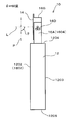
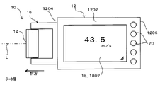
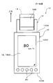
- a moving body speed measurement device 10 (hereinafter simply referred to as a speed measurement device 10) includes a housing 12, an antenna 14, an antenna support unit 16, a display unit 18, and an operation unit 20. It is configured to include.
- the housing 12 has a rectangular plate shape having a vertical thickness, a horizontal width greater than the thickness, and a front-rear length greater than the width.
- the upper surface 1202 of the housing 12 has a substantially rectangular shape with the longitudinal direction parallel to the front-rear direction of the housing 12.
- the front and rear surfaces of the upper surface 1202 are connected to the front surface 1204 and the rear surface 1206 of the housing 12, respectively.
- a lower surface 1203 facing the upper surface 1202 is provided with a female screw (camera screw) (not shown) for attaching the speed measuring device 10 to a fixture such as a tripod.
- the antenna 14 is connected to the upper surface 1202 of the housing 12 via the antenna support 16.
- the antenna 14 has directivity, and transmits a transmission wave toward the mobile body based on a transmission signal supplied from a Doppler sensor 22 (FIG. 6) described later, and receives a reflected wave reflected by the mobile body. Thus, a reception signal is generated and supplied to the Doppler sensor 22.
- a virtual line extending along the direction in which the gain of the antenna 14 is maximized is defined as a virtual axis L that indicates the directivity direction of the antenna.
- the antenna 14 is configured by a rectangular plate-shaped patch antenna, and one surface in the thickness direction is a surface that transmits a transmission wave and receives a reflected wave, and the opposite side of the surface is a back surface. ing.
- a patch antenna is used as the antenna 14, it is advantageous in reducing the size of the speed measuring device 10.
- various conventionally known antennas such as a horn antenna can be used as the antenna 14. If the directivity angle of the antenna 14 is too narrow, there is a disadvantage that the measurement range of the moving body is limited. If the directivity angle of the antenna 14 is too wide, an unnecessary reflected wave from an object other than the mobile object to be measured. This is disadvantageous in ensuring measurement accuracy. For this reason, it is advantageous that the directivity angle of the antenna 14 is set to 5 to 90 degrees in order to suppress reception of unnecessary reflected waves from an object that is not the object of measurement while ensuring the measurement range of the moving body.
- the antenna support unit 16 is provided in the housing 12 and supports the antenna 14 so that the inclination of the virtual axis L can be changed.
- the antenna support portion 16 includes a frame 16A and a case 16B.
- the frame 16 ⁇ / b> A includes a base portion 1602 that is provided on the front surface 1204 of the housing 12 and extends in the width direction of the housing 12, and two column portions 1604 that stand forward from both ends of the base portion 1602.
- the case 16B has a rectangular plate shape that is slightly smaller than the outline when the antenna 14 is viewed in plan, and is attached to the back surface of the antenna 14 with the four sides of the case 16B parallel to the four sides of the antenna 14. Yes.
- the case 16B has a rectangular plate-like bottom wall facing the antenna 14 and four side walls standing up from the bottom wall, and the upper parts of these four side walls are connected to the back surface of the antenna 14. ing.
- a Doppler sensor 22 (to be described later) is accommodated in an accommodation space surrounded by the bottom wall, the four bottom walls, and the antenna 14.
- an integrated module in which the antenna 14 and the Doppler sensor 22 are integrally provided may be used.
- the Doppler sensor 22 is integrally provided on the back surface of the antenna 14.
- the Doppler sensor 22 may be housed in the housing 12.
- two opposite side walls of the four side walls are disposed between the two column portions 1604, and the two column portions 1604 are connected to the two column portions 1604 via a support shaft 16C whose axial center is directed in the left-right direction of the housing 12. It is rotatably supported. Therefore, the antenna support unit 16 supports the antenna 14 so that the inclination of the virtual axis L can be changed.
- an angle formed by a virtual axis L and a virtual plane P parallel to a display surface 1802 of the display unit 18 described later is defined as an antenna angle ⁇ .
- the antenna support portion 16 supports the antenna 14 so that the antenna angle ⁇ changes within a range of ⁇ 90 degrees.
- the antenna angle ⁇ changes in the range of 180 degrees.
- the adjustment range of the antenna angle ⁇ is not limited to 180 degrees, and how the adjustment range is set is arbitrary.
- the antenna angle ⁇ is +90 degrees with the virtual axis L facing upward of the housing 12, and the virtual axis L faces forward of the housing 12 as shown in FIG. 5.
- the antenna angle ⁇ 0 degrees
- the antenna angle ⁇ ⁇ 90 degrees in a state where the virtual axis L faces the rear of the housing 12, and thus the adjustment range of the antenna angle ⁇ is ⁇ 90 degrees.
- the antenna support 16 supports the antenna 14 so as to be rotatable about the single support shaft 16C.
- the antenna support 16 can change the inclination of the virtual axis L.
- various conventionally known mechanisms can be used as the antenna support portion 16.
- the antenna support portion 16 may be configured to support the antenna 14 so as to be rotatable about two support shafts by further providing another support shaft extending on a plane orthogonal to the support shaft 16C. This is more advantageous in securing the degree of freedom in adjusting the inclination of the virtual axis L of the antenna 14.
- the antenna support unit 16 includes a click mechanism that holds the antenna 14 at a plurality of predetermined antenna angles ⁇ , for example, three angles of +90 degrees, 0 degrees, and ⁇ 90 degrees. Yes. This facilitates the setting operation to a plurality of predetermined antenna angles ⁇ .
- the antenna support unit 16 is provided with an angle display unit 16D that indicates which of the plurality of predetermined antenna angles ⁇ is located. It has been. This facilitates confirmation of the antenna angle ⁇ .
- the angle display portion 16D is configured by a window portion provided in one pillar portion 1604 and an index provided in the case 16B.
- the index is formed by a symbol such as A, B, or C, a numeral, a scale line, or the like at the location of the case 16B corresponding to the antenna angle ⁇ of +90 degrees, 0 degrees, and ⁇ 90 degrees.
- the antenna angle ⁇ of the antenna 14 is switched to +90 degrees, 0 degrees, and ⁇ 90 degrees, the indicators A, B, and C formed at the location of the case 16B are selectively exposed through the window. As a result, it is indicated at which of the plurality of antenna angles ⁇ the antenna 14 is located.
- Various conventionally known display mechanisms can be used as such an angle display unit 16D.
- the display unit 18 is provided on the upper surface 1202 of the housing 12 with the rectangular flat display surface 1802 facing upward, and most of the upper surface 1202 is occupied by the display surface 1802.
- the display surface 1802 has a rectangular shape whose length along the front-rear direction of the housing 12 is shorter than the width along the left-right direction of the housing 12.
- the display unit 18 displays various display contents including the moving speed of the moving body as a measurement result on the display surface 1802 in the form of numbers, symbols, icons, and the like.
- a flat panel display such as a liquid crystal panel can be used.
- the operation unit 20 is provided near the rear surface 1206 of the upper surface 1202.
- the operation unit 20 includes a plurality of operation buttons including a mode selection button and a power button.
- the mode selection button is used to select a measurement mode of the speed measurement device 10 from among a golf mode, a bat mode, and a ball mode, which will be described later.
- the power button is for turning the power on and off.
- the posture of the housing 12 when using the speed measuring device 10 is not particularly limited. Usually, however, (1) a posture with the upper surface 1202 (display surface 1802) of the housing 12 facing upward, (2) Any one of the postures in which the front surface 1204 of the housing 12 faces upward and the upper surface 1202 (display surface 1802) faces sideways, and the antenna 14 has an imaginary axis L that matches the moving direction of the moving body Adjust the angle ⁇ .
- the speed measurement device 10 includes a Doppler sensor 22, a measurement processing unit 24, and the like in addition to the antenna 14, the display unit 18, and the operation unit 20.
- the Doppler sensor 22 is connected to the antenna 14 via a cable (not shown), supplies a transmission signal to the antenna 14 via the cable, and receives a reception signal supplied from the antenna 14 to detect the Doppler signal Sd. is there.
- the Doppler signal is a signal having a Doppler frequency Fd defined by a frequency F1-F2 that is a difference between the frequency F1 of the transmission signal and the frequency F2 of the reception signal.
- Various commercially available Doppler sensors 18 can be used.
- As the transmission signal for example, a microwave of 24 GHz or 10 GHz can be used, and the frequency of the transmission signal is not limited as long as the Doppler signal Sd can be obtained.
- reference numeral 2 denotes a golf club
- reference numeral 4 denotes a golf club head as a moving body
- reference numeral 6 denotes a golf ball as a moving body.
- the Doppler frequency Fd is expressed by Expression (1).
- V speed of moving object
- c speed of light (3 ⁇ 10 8 m / s) Therefore, when equation (1) is solved for V, equation (2) is obtained.
- V c ⁇ Fd / (2 ⁇ F1) (2) Therefore, the speed V of the moving body is proportional to the Doppler frequency Fd.
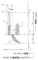
- FIG. 8 is a diagram illustrating a result of wavelet analysis of the Doppler signal Sd.
- the horizontal axis represents time t (ms), and the vertical axis represents the Doppler frequency Fd (Hz) and the velocity V (m / s) of the moving object.
- Such a diagram can be obtained, for example, by sampling the Doppler signal Sd, taking it into a digital oscilloscope and converting it into digital data, and then performing wavelet analysis or continuous FFT analysis on the digital data using a personal computer or the like. .
- FIG. 8 shows a process before and after the golf ball 6 placed on the tee is hit by the swinged golf club head 4.
- the frequency distribution (velocity distribution) indicated by the symbol A indicates the detection result of the Doppler frequency Fd (velocity V) corresponding to the golf club head 4 during the period until the golf ball 6 is hit.
- the frequency distribution (velocity distribution) indicated by the symbol B indicates the detection result of the Doppler frequency Fd (velocity V) corresponding to the golf ball 6 in the period after being hit with the golf club head 4.
- the frequency distribution (velocity distribution) indicated by the symbol C indicates the detection result of the Doppler frequency Fd (speed V) corresponding to the golf club head 4 in the period after the golf ball 6 is hit.
- the portions indicated by hatching have a large intensity of the Doppler signal Sd
- the portions indicated by a solid line have a lower intensity than the portion indicated by the hatching. Is shown.
- the frequency distribution A indicates a process in which the golf club head 4 that has been swung is measured from the time when it enters the detection region of the Doppler sensor 18 and increases with time.
- the frequency distribution C indicates a process in which the golf club head 4 is rapidly decelerated by hitting the golf ball 6.
- the frequency distribution B shows a process in which the golf ball 6 hit with the golf club head 4 is launched at a speed higher than the maximum speed of the golf club head 4 in the frequency distribution A and moves at a substantially constant speed.
- the moving speed V (Doppler frequency Fd) of the golf club head 4 is greatly reduced by hitting the golf ball 6. That is, the amount of change per unit time of the moving speed V (Doppler frequency Fd) of the golf club head 4 changes greatly when the golf ball 6 is hit.
- the maximum speed of the golf club head 4 (so-called head speed) is the maximum speed of the moving speed V of the golf club head 4 in the period before hitting. That is, the maximum speed of the golf club head 4 is a moving speed corresponding to the maximum frequency of the Doppler frequency Fd in the frequency distribution A of FIG. (2)
- the moving speed V (Doppler frequency Fd) of the golf ball 6 can be regarded as a substantially constant speed after being hit by the golf club head 4.
- the initial speed of the golf ball 6 is a moving speed corresponding to the Doppler frequency Fd in the frequency distribution B of FIG. (3) Therefore, the maximum speed of the golf club head 4 can be measured by determining the frequency distribution A and obtaining the maximum speed in the frequency distribution A. Further, the initial velocity of the golf ball 6 can be measured by determining the frequency distribution B and obtaining the average velocity in the frequency distribution B. In the present embodiment, based on such knowledge, the moving speeds of the moving bodies are accurately measured based on the fact that the changes in the moving speeds of the moving bodies have different tendencies and characteristics from each other. Is.
- the measurement processing unit 24 calculates the moving speed of the moving body (the golf club head 4 and the golf ball 6) by inputting the Doppler signal Sd supplied from the Doppler sensor 22 and performing arithmetic processing.
- the measurement processing unit 24 is configured by a microcomputer 26.
- the microcomputer 26 includes a CPU 26A, a ROM 26B, a RAM 26C, an interface 26D, a display driver 26E, and the like connected via an interface circuit (not shown) and a bus line.
- the ROM 26B stores a control program for calculating the moving direction and moving speed of the moving body executed by the CPU 26A, and the RAM 26C provides a working area.
- the interface 26D inputs the Doppler signal Sd and supplies it to the CPU 26A, and receives an operation signal from the operation unit 20 and supplies it to the CPU 26A.
- the display driver 26E drives the display unit 22 based on the control of the CPU 26A.
- FIG. 7 is a block diagram of the speed measuring device 10 showing the configuration of the microcomputer 26 as functional blocks.
- the microcomputer 26 is functionally configured to include storage means 28, calculation means 30, and control means 32. Further, the storage means 28, the arithmetic means 30, and the control means 32 are realized by the CPU 26A executing the control program. These parts are configured by hardware such as a circuit. It may be a thing.
- the accumulating means 28 samples the Doppler signal Sd at a predetermined sampling period, converts it into intermediate data associated with the Doppler frequency Fd, and accumulates the data sequentially in accordance with the passage of time.
- the intermediate data is stored in the RAM 26C.
- the intermediate data can be generated as follows. (1) The Doppler signal Sd is binarized to generate a binarized signal, and the binarized signal is counted using a counter to obtain the cycle of the binarized signal. Data. In this case, the value of the intermediate data and the Doppler frequency Fd are inversely proportional. (2) The frequency of the Doppler frequency Fd is obtained as intermediate data, and the data at this frequency is sampled to obtain intermediate data.
- the intermediate data indicates the Doppler frequency Fd itself.
- the intermediate data is obtained by the method (1)
- the configuration of the processing circuit becomes complicated and the processing time becomes long, such as FFT conversion as signal processing.
- the configuration of the processing circuit is simplified, which is advantageous for shortening the processing time.
- the calculation means 30 detects a boundary point where a sudden change in the moving speed of the moving body is based on the accumulated intermediate data, and first speed data as the maximum speed of the moving speed in the first period before the boundary point. And second speed data as an average speed of the moving speed in the second period after the boundary point.
- the computing unit 30 includes a determination unit 30A, a period setting unit 30B, and a speed calculation unit 30C.
- the determination unit 30A determines whether or not the numerical value of the intermediate data stored in the storage unit 28 has increased or decreased continuously over time (N is a natural number of 2 or more) over time. It is determined whether or not the speed has suddenly decreased. In the present embodiment, since the intermediate data indicates a cycle, it is determined whether or not the number of intermediate data has increased continuously over time (N is a natural number of 2 or more) as time passes. It is determined whether or not the speed has suddenly decreased. That is, when the moving body is the two moving bodies of the golf club head 4 and the golf ball 6, when the golf club head 4 moves and hits the golf ball 6 in a stationary state, the moving speed of the golf club head 4 is hit. The golf ball 6 is launched by decelerating rapidly at the time point. In other words, the determination unit 30A determines whether or not the moving speed of one moving body has suddenly decreased as one moving body strikes the other moving body. When the golf club head 4 hits the golf ball 6, the head speed is reduced by about 1 to 10 m / s.
- the determination unit 30A determines whether or not the absolute value of the amount of change per unit time of the intermediate data stored in the storage unit 28 exceeds a predetermined threshold value, so that the moving speed of the moving body is rapidly increased. It is determined whether or not the vehicle has slowed down. However, if the determination means 30A determines whether or not the numerical value of the intermediate data stored in the storage means 28 has increased or decreased continuously over time as described above, the intermediate data This is more advantageous in suppressing the influence of noise included in the determination result on the determination result.
- the noise included in the intermediate data is caused by the noise included in the Doppler signal Sd.
- the period setting unit 30B performs the following operation when the determination result by the determination unit 30A is affirmative. That is, as shown in FIG. 8, the period setting unit 30B sets the boundary point t0 when the numerical value increases or decreases continuously for N intermediate data.
- the period setting means 30B sets the period from the sampling time t1 of the leading data of the intermediate data to the boundary point t0 as the first period ⁇ T1, and sets the period from the boundary point t0 to the sampling time t2 of the final data of the intermediate data as the second period ⁇ T2.
- the determination unit 30A determines whether or not the absolute value of the amount of change per unit time of the intermediate data stored in the storage unit 28 exceeds a predetermined threshold value, so that the moving speed of the moving body is rapidly increased. In the case where it is determined whether or not the vehicle has been decelerated, the period setting unit 30B sets the time point when the absolute value of the change amount exceeds the threshold value as the boundary point t0.
- the speed calculation unit 30C performs a first calculation operation for obtaining the first speed data V1 (FIG. 8) as the maximum speed based on the minimum value or the maximum value of the intermediate data in the first period ⁇ T1.
- the speed calculation means 30C obtains the first speed data V1 (FIG. 8) as the maximum speed based on the minimum value of the intermediate data in the first period ⁇ T1.
- Perform arithmetic operations That is, when the golf ball 6 is hit with the golf club head 4, the first speed data V ⁇ b> 1 indicates the head speed of the golf club head 4.
- the speed calculation means 30C performs a second calculation operation for obtaining the second speed data V2 (FIG.
- the second speed data V ⁇ b> 2 indicates the initial speed of the golf ball 6.
- the second arithmetic operation by the speed calculating unit 30C is made to the intermediate data corresponding to between the upper limit value D H and the lower limit D L predetermined in the second period Delta] T2.
- the upper limit value DH is a value obtained by multiplying intermediate data corresponding to the first speed data V1 by a predetermined first coefficient k1, and the lower limit value DL is set to intermediate data corresponding to the first speed data V1.
- the first coefficient k1 and the second coefficient k2 can be set between 1.1 and 1.9, for example.
- the speed calculation means 30C when the determination result by the determination means 30A is negative, the third speed data V3 as the maximum speed based on the minimum value or the maximum value of all the intermediate data stored in the storage means 28.
- the third calculation operation for obtaining the above is performed.
- the third speed data V3 is the head speed of the golf club head 4.
- the speed calculation means 30C sets the minimum value of all the intermediate data stored in the storage means 28 when the determination result by the determination means 30A is negative. Based on this, the third calculation operation for obtaining the third speed data V3 as the maximum speed is performed.
- the speed calculation means 30C obtains fourth speed data V4 as an average speed based on the average value of all intermediate data stored in the storage means 28 when the determination result by the determination means 30A is negative. Perform 4 arithmetic operations.
- the fourth calculation operation is not effective when the golf ball 6 is hit with the golf club head 4, but is effective, for example, when measuring the moving speed of the ball when a baseball is thrown. Accordingly, in this case, the fourth speed data V4 is the speed of the pitched baseball.
- the control means 32 accepts the operation of the operation unit 20 and sets any measurement mode of the golf mode, the bat mode, and the ball mode. That is, the control unit 32 controls the speed calculation unit 30C according to the set measurement mode to execute the first to fourth calculation operations. Further, the control means 32 causes the display unit 18 to display the first to fourth speed data V1 to V4.
- the moving body is two moving bodies of the golf club head 4 and the golf ball 6, and the moving speed of the two moving bodies is both the head speed of the golf club head 4 and the initial speed of the golf ball 6.
- FIG. 9 is a plan view for explaining the installation state of the speed measuring device 10 when measuring the golf club head 4 and the golf ball 6 as a moving body, and FIG. It is a flowchart which shows operation
- the user operates a mode selection button to select a golf mode, a bat mode, or a ball mode as a measurement mode of the speed measurement device 10.
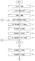
- the golf mode is set in response to the operation of the mode selection button (step S10).
- the golf mode is a mode in which both the first and second speed data V1 and V2 are measured and displayed.
- the user installs the speed measuring device 10 at a location, for example, about 1 m to 1.5 m behind the golf ball 6 in the launch direction of the golf ball 6. That is, the front surface 1204 of the speed measuring device 10 is directed in the launch direction, the lower surface is directed to the ground, and the upper surface 1202 and the display surface 1802 are directed upward.
- the antenna angle ⁇ of the antenna 14 is adjusted so that the virtual axis L faces the golf ball 6 and matches the launch direction. In this case, the antenna angle ⁇ is, for example, 0 degrees.
- the speed measurement device 10 may be placed on the ground, or may be installed via a fixture such as a tripod. As a result, the transmission wave W1 transmitted from the antenna 14 hits the golf ball 6 and the golf club head 4, and the reflected wave W2 can be received by the antenna 14. Further, the user M can easily see the display surface 1802.
- the measuring operation by the speed measuring device 10 is executed. Specifically, the transmission wave W1 is reflected by the golf club head 4 and the golf ball 6, the reflected wave W2 is received by the Doppler sensor 18, and the Doppler sensor 18 generates the Doppler signal Sd (Step S12).
- the Doppler signal Sd is sampled at the sampling period by the storage means 28, converted into intermediate data associated with the Doppler frequency Fd, and stored as time series data in the storage means 28 (step S14).
- the determination unit 30A determines whether or not the number of intermediate data stored in the storage unit 28 has increased continuously over time (N is a natural number of 2 or more) with time (step S16). If step S16 is positive, the period setting unit 30B sets the first period ⁇ T1 and the second period ⁇ T2 based on the intermediate data stored in the storage unit 28 (step S18).
- the control unit 44 controls the speed calculation means 30C, so that the speed calculation means 30C obtains the first speed data V1 and the first calculation operation and the second speed.
- a second calculation operation for obtaining data V2 is executed (steps S20 and S22).
- the control means 32 displays the first speed data V1 on the display surface 1802 as the head speed, displays the second speed data V2 on the display surface 1802 as the initial ball speed (step S24), and ends the measurement operation.
- step S16 the speed calculation means 30C performs a third calculation operation for obtaining the third speed data V3 (step S26). That is, if step S16 is negative, the golf club 2 is swinging, but the golf club head 4 is not hit by the golf ball 6, and so-called swing is made. Therefore, in this case, only the third speed data V3 as the head speed of the golf club head 4 may be measured and displayed.
- the control means 32 displays the third speed data V3 on the display surface 1802 as the head speed (step S28), and ends the measurement operation.
- the unit of speed displayed on the display surface 1802 is set to either m / s or MPH.
- the display format of the first, second speed data V1, V2 or the third speed data V3 is arbitrary. Specifically, by performing an operation for setting a display mode for selecting a display mode on the operation unit 20, the control unit 32 accepts the operation, and both the first and second speed data V1 and V2 are received. Alternatively, one of them may be displayed.
- the initial speed efficiency R may be calculated by the control means 32 and displayed on the display unit 18 together with the first speed data V1.
- the initial speed efficiency R corresponds to the ratio of the second speed data V2 to the first speed data V1, as shown by the equation (3).
- R (V2 / V1) (3)
- the ratio of the initial speed efficiency R to the predetermined maximum value Rm (theoretical maximum efficiency) of the initial speed efficiency R is calculated as the impact efficiency Ip, and this impact efficiency Ip is calculated as the first speed.
- Ip (R / Rm) ⁇ 100 (%) (4) Examples of numerical values are as follows.
- V1 40 m / s
- V2 60 m / s
- Ip 100%
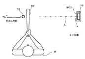
- FIG. 10 is a plan view for explaining the installation state of the speed measuring device 10 when the baseball bat 50 is measured as a moving body
- FIG. 15 is a plan view of the speed measuring device 10 when the baseball bat 50 is measured as a moving body. It is a flowchart which shows operation
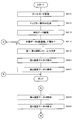
- the user M operates the mode selection button to select the golf mode, the bat mode, or the ball mode as the measurement mode of the speed measurement device 10, and the control unit 32. Accepts the operation of the mode selection button to set the bat mode (step S110).
- the user M for example, from the ball 52 in the launch direction of the ball 52 placed on the tee (in the direction along the straight line connecting the home base and the pitcher) is 1.5 m to
- the speed measuring device 10 is installed at a location about 2.0 m behind. That is, the upper surface 1202 (display surface 1802) of the speed measuring device 10 is directed in the launch direction, the front surface 1204 is directed upward, and the rear surface 1206 is directed to the ground. Then, the antenna angle ⁇ of the antenna 14 is adjusted so that the virtual axis L matches the launch direction. In this case, the antenna angle ⁇ is, for example, +90 degrees.
- the speed measurement device 10 may be placed on the ground, or may be installed via a fixture such as a tripod. As a result, the transmission wave W1 transmitted from the antenna 14 hits the bat 50, and the reflected wave W2 becomes receivable by the antenna 14. Further, the user M can easily see the display surface 1802.
- steps S114 and S116 are the same as steps S14 and S16 in FIG.
- step S116 the speed calculation unit 30C performs a third calculation operation for obtaining the third speed data V3 (step S126).
- the control means 32 displays the third speed data V3 on the display surface 1802 as a swing speed (step S128), and ends the measurement operation.
- the speed unit displayed on the display surface 1802 by the control means 32 is set to km / h in advance.
- step S116 if step S116 is positive, steps S118 and S120 are executed.
- the processing in steps S118 and S120 is the same as that in steps S18 and S20 in FIG.
- the control means 32 displays the first speed data V1 on the display surface 1802 as a swing speed (step S122), and ends the measurement operation.
- the unit of speed displayed on the display surface is set to km / h.
- step S116 will be described in more detail.
- a microwave is used as the transmission wave W1
- a reflected wave W2 is generated in the baseball bat 50, whereas most of the transmission wave W1 is absorbed depending on the material of the baseball ball 52, so the reflected wave W2 is reflected. The strength of may be lowered. For this reason, the Doppler signal Sd generated by the reflected wave W2 from the ball 52 is not recognized as a valid signal in the signal processing circuit 28, and therefore, the binarized signal is not detected.
- S126 and S128 are executed.
- the intermediate data stored in the storage means 28 is stored.
- the included error is large.
- the third speed data V3 is obtained using the intermediate data including the error, the accuracy of the third speed data V3 is lowered. Therefore, when step S116 is affirmative, the first speed data V1 is measured using only the intermediate data of the first period ⁇ T1, and the first speed data V1 is displayed on the display surface 1802. Thereby, the speed of the bat 50 excluding the influence of the ball 52 can be accurately measured and displayed.
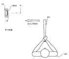
- FIG. 11 is a plan view for explaining another example of the installation state of the speed measurement device 10 when measuring the baseball bat 50 as a moving body. Then, the speed when the user M1 swings the bat 50 is measured. In this case, the user M1 installs the speed measuring device 10 at a location about 1.5 m to 2.0 m ahead of the user M1 in the swing direction of the bat 50, for example. That is, the upper surface 1202 (display surface 1802) of the speed measuring device 10 is directed rearward, the front surface 1204 is directed upward, and the rear surface 1206 is directed to the ground.
- the antenna angle ⁇ of the antenna 14 is adjusted so that the virtual axis L coincides with the direction opposite to the swing direction (rearward).
- the antenna angle ⁇ is, for example, +90 degrees.
- the speed measurement device 10 may be placed on the ground, or may be installed via a fixture such as a tripod. As a result, the transmission wave W1 transmitted from the antenna 14 hits the bat 50, and the reflected wave W2 becomes receivable by the antenna 14. Further, the user M1 can easily view the display surface 1802.
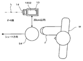
- FIG. 12 is a plan view for explaining an installation state of the speed measuring device 10 when measuring the soccer ball 54 as a moving body
- FIG. 16 is a plan view of the speed measuring device 10 when measuring the soccer ball 54 as a moving body. It is a flowchart which shows operation
- the user M operates the mode selection button to select a golf mode, a bat mode, or a ball mode as the measurement mode of the speed measurement device 10, and the control means 32. Accepts the operation of the mode selection button to set the ball mode (step S210).
- the user M installs the speed measuring device 10 at a location separated from the ball 54 within, for example, about 30 cm in a direction orthogonal to the chute direction of the ball 54. That is, the front surface 1204 of the speed measuring device 10 is directed in the chute direction, the lower surface is directed to the ground, and the upper surface 1202 and the display surface 1802 are directed upward. Then, the antenna angle ⁇ of the antenna 14 is adjusted so that the virtual axis L coincides with the chute direction. In this case, the antenna angle ⁇ is, for example, 0 degrees.
- the speed measurement device 10 may be placed on the ground, or may be installed via a fixture such as a tripod. As a result, the transmission wave W1 transmitted from the antenna 14 hits the ball 54, and the reflected wave W2 can be received by the antenna 14. Further, the user M can easily see the display surface 1802.
- Step S212 when the user M kicks the ball 54 with the foot F, the measuring operation by the speed measuring device 10 is executed. Specifically, the transmission wave W1 is reflected by the foot F of the user M and the ball 54, the reflected wave W2 is received by the Doppler sensor 18, and the Doppler sensor 18 generates the Doppler signal Sd (Step S212).
- steps S214 and S216 are the same as steps S14 and S16 in FIG.
- step S216 the speed calculation means 30C performs a fourth calculation operation for obtaining the fourth speed data V4 (step S226).
- the control means 32 displays the fourth speed data V4 as the ball speed on the display surface 1802 (step S228), and ends the measurement operation.
- the speed unit displayed on the display surface 1802 by the control means 32 is set to km / h in advance.
- step S216 if step S216 is positive, steps S218 and S220 are executed.
- the processing in steps S218 and S220 is the same as that in steps S18 and S22 in FIG.
- the control means 32 displays the second speed data V2 on the display surface 1802 as the ball speed (step S224), and ends the measurement operation.
- step S216 The determination in step S216 will be described in more detail.
- the reflected wave W2 is generated in the soccer ball 54, whereas the foot F of the user M usually absorbs most of the transmission wave W1 due to its physical characteristics. Therefore, the intensity of the reflected wave W2 is low.
- the Doppler signal Sd generated by the reflected wave W2 from the foot F is not recognized as a valid signal by the signal processing circuit 28, and therefore, the binarized signal is not detected.
- S226 and S228 are executed.
- the Doppler signal generated by the reflected wave W2 from the foot F is recognized as a valid signal by the signal processing circuit 28 and a binarized signal is detected, the intermediate data stored in the storage means 28 is stored.
- step S216 when the fourth speed data V4 is obtained using the intermediate data including the error, the accuracy of the fourth speed data V4 is lowered. Therefore, when step S216 becomes affirmative, the second speed data V2 is measured using only the intermediate data in the second period ⁇ T2, and the second speed data V2 is displayed on the display surface 1802. Thereby, the speed of the ball 54 excluding the influence of the foot F can be accurately measured and displayed.
- FIG. 13 is a plan view for explaining the installation state of the speed measuring device 10 when measuring the baseball ball 56 as a moving body
- FIG. 17 is a plan view of the speed measuring device 10 when measuring the baseball ball 56 as a moving body. It is a flowchart which shows operation
- the user M operates the mode selection button to select a golf mode, a bat mode, or a ball mode as the measurement mode of the speed measurement device 10, and the control means 32. Accepts the operation of the mode selection button to set the ball mode (step S310).
- the user M is, for example, 1.5 m from the standing position of the user M in the pitching direction of the ball 56 (in a direction along a straight line connecting the home base and the pitcher).
- the speed measuring device 10 is installed at a location in front of about 2.0 m. That is, the upper surface 1202 (display surface 1802) of the speed measuring device 10 is directed in the direction opposite to the pitching direction, the front surface 1204 is directed upward, and the rear surface 1206 is directed to the ground.
- the antenna angle ⁇ of the antenna 14 is adjusted so that the virtual axis L coincides with the pitching direction. In this case, the antenna angle ⁇ is, for example, 0 degrees.
- the speed measurement device 10 may be placed on the ground, or may be installed via a fixture such as a tripod. As a result, the transmission wave W1 transmitted from the antenna 14 hits the ball 56, and the reflected wave W2 can be received by the antenna 14. Further, the user M can easily see the display surface 1802. Alternatively, as shown by the symbol B in FIG. 13, the user M installs the speed measurement device 10 at a location about 1.5 m to 2.0 m behind the standing position of the user M in the pitching direction of the ball 56, for example. . That is, the upper surface 1202 (display surface 1802) of the speed measuring device 10 is directed in the same direction as the pitching direction, the front surface 1204 is directed upward, and the rear surface 1206 is directed to the ground.
- the antenna angle ⁇ of the antenna 14 is adjusted so that the virtual axis L coincides with the pitching direction.
- the antenna angle ⁇ is, for example, ⁇ 90 degrees.
- the speed measuring device 10 may be placed on the ground in the same manner as described above, or may be installed via a fixture such as a tripod. As a result, the transmission wave W1 transmitted from the antenna 14 hits the ball 56, and the reflected wave W2 can be received by the antenna 14. Further, the user M can easily see the display surface 1802. Therefore, the speed measuring device 10 can be installed at one of the positions of the symbols A and B.
- the moving direction of the ball 54 viewed from the speed measuring device 10 is the approaching direction
- the speed measuring device 10 is installed at the position of the symbol B
- the moving direction of the ball 56 as viewed from the speed measuring device 10 is a separating direction.
- the absolute value of the calculated moving speed is the same in any case, the absolute value of the calculated moving speed may be displayed on the display surface.
- step S312 the processing of steps S314 and S316 is the same as steps S14 and S16 of FIG.
- step S316 the speed calculation means 30C performs a fourth calculation operation for obtaining the fourth speed data V4 (step S326).
- the control means 32 displays the fourth speed data V4 on the display surface 1802 as the ball speed (step S328), and ends the measurement operation.
- step S316 if step S316 is positive, steps S318 and S320 are executed.
- the processing in steps S318 and S320 is the same as that in steps S18 and S22 in FIG.
- the control means 32 displays the second speed data V2 on the display surface 1802 as the ball speed (step S324), and ends the measurement operation.
- step S316 The determination in step S316 will be described in more detail.
- the microwave is used as the transmission wave W1
- the reflected wave W2 is generated in the baseball 56
- the physical movement of the hand H of the user M is usually the same as in the case of the foot F. Since most of the transmitted wave W1 is absorbed from the characteristics, the intensity of the reflected wave W2 is low. For this reason, the Doppler signal Sd generated by the reflected wave W2 from the hand H is not recognized as a valid signal in the signal processing circuit 28, and therefore, the binarized signal is not detected, so the determination in step S316 is negative, and the step S326 and S328 are executed.
- the intermediate data stored in the storage means 28 is stored.
- the included error is large.
- the fourth speed data V4 is obtained using the intermediate data including the error, the accuracy of the fourth speed data V4 is lowered. Therefore, when step S316 is affirmative, the second speed data V2 is measured using only the intermediate data of the second period ⁇ T2, and the second speed data V2 is displayed on the display surface 1802. Thereby, the speed of the ball 54 excluding the influence of the hand H can be accurately measured and displayed.
- the antenna 14 is supported on the housing 12 that holds the display unit 18 so that the inclination of the virtual axis L of the antenna 14 can be changed.
- An antenna support 16 was provided. Therefore, the display unit 18 can be easily viewed by the user, and the moving direction of the moving body and the virtual axis L of the antenna 14 can be matched. Therefore, both the visibility of the display unit 18 and the measurement accuracy of the moving speed of the moving body can be ensured in various measurement states. Even if the place where the speed measuring device 10 is installed is uneven or inclined, the virtual axis L can be matched with the moving direction of the moving body by adjusting the inclination of the virtual axis L of the antenna 14. Therefore, the measurement accuracy of the moving speed of the moving body can be ensured.
- the antenna support unit 16 supports the antenna 14 in a range where the antenna angle ⁇ between the virtual axis L and the virtual plane P parallel to the flat display surface 1802 of the display unit 18 is ⁇ 90 degrees. It is made to change. Therefore, since the direction of the display surface 1802 and the direction of the virtual axis L of the antenna 14 can be adjusted from the same direction to the opposite direction, the visibility of the display unit 18 and the measurement accuracy of the moving speed of the moving body can be improved. It is more advantageous in securing both.
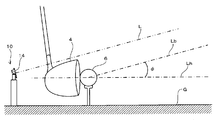
- the golf club head 4 moved at the time of hitting is substantially horizontal, whereas the hit golf
- the moving direction of the ball 6 varies depending on the angle between the face surface of the golf club head 4 and the horizontal plane G (ground).
- the angle between the face surface of the golf club head 4 and the horizontal plane G is the loft angle of the golf club head 4.
- the direction of the virtual axis L of the antenna 14 is matched with the moving direction of the golf ball 6 (parallel to the moving track Lb of the golf ball 6)
- the virtual axis L of the antenna 14 and the moving direction of the golf club head 4 do not match.
- the measurement accuracy of the moving speed of the golf ball 6 can be ensured, the measurement accuracy of the moving speed of the golf club head 4 is lowered.
- the virtual axis L of the antenna 14 is matched with the moving direction of the golf club head 4 (parallel to the moving locus Lb of the golf club head 4). ), The direction of the virtual axis L of the antenna 14 and the moving direction of the golf ball 6 do not match. Therefore, in this case, although the measurement accuracy of the moving speed of the golf club head 4 can be ensured, the measurement accuracy of the moving speed of the golf ball 6 is lowered.
- the movement locus Lh of the golf club head 4 is assumed to be virtual.
- the angle formed by the movement locus Lh of the golf club head 4 and the virtual axis L is a deviation angle ⁇ .
- the error included in the moving speed of the golf club head 4 calculated by the measurement processing unit 24 increases.
- the shift angle ⁇ and the error have a certain correlation.
- a moving speed correction unit 30D is provided as shown in FIG.
- the moving speed correction unit 30D determines the golf club based on the specified deviation angle ⁇ so as to eliminate the error included in the moving speed (first moving speed) of the golf club head 4 calculated by the speed calculating unit 30C.
- the movement calculation of the head 4 is corrected. Therefore, the control unit 32 causes the display unit 18 to display the moving speed of the golf ball 6 calculated by the speed calculating unit 30C and the moving speed of the golf club head 4 corrected by the moving speed correcting unit 30D.
- the designation of the shift angle ⁇ with respect to the moving speed correction unit 30D can be performed as follows. That is, the loft angle of the golf club head 4 is used as the deviation angle ⁇ .
- the control means 32 receives the input shift angle ⁇ and sets it in the movement speed correction unit 30D.
- FIG. 19 shows a case where the golf club head 4 is a wood club and the loft angle is small
- FIG. 20 shows a case where the golf club head 4 is an iron club and a loft angle is large.
- the antenna angle ⁇ is determined corresponding to the loft angle.
- the shift angle ⁇ is determined in accordance with the loft angle as described above. Therefore, the antenna angle ⁇ and the shift angle ⁇ are associated in advance, and the shift angle ⁇ can be specified if the antenna angle ⁇ is determined. Therefore, in the second embodiment, an antenna angle detection unit 34 that detects the antenna angle ⁇ is provided, and the correction calculation performed by the moving speed correction unit 30D is associated with the antenna angle ⁇ detected by the antenna angle detection unit 34.
- the antenna angle detector 34 is, for example, provided in the case 16B of the antenna support 16 and can be constituted by an angle sensor that detects the amount of rotation of the case 16B around the support shaft 16C. Various known sensors can be used.
- the movement locus Lh of the golf club head 4 in a state where the virtual axis L is matched with the moving direction of the golf ball 6 (second moving body). Is corrected on the moving speed of the golf club head 4 based on the deviation angle ⁇ between the moving locus and the virtual axis L when projected onto a virtual plane including the virtual axis L and extending in the vertical direction. I did it. Therefore, it is advantageous in ensuring the measurement accuracy of the moving speeds of both the golf club head 4 and the golf ball 6. Since the correction calculation by the moving speed correction unit 30D is performed by specifying the shift angle ⁇ associated with the antenna angle ⁇ detected by the antenna angle detection unit 34, the shift angle ⁇ is set to the operation unit. This eliminates the need for complicated operations such as input using 20, which is advantageous in improving operability.
- the posture of the casing 12 of the speed measuring device 10 depends on the measurement situation, that is, the type of ball to be measured (type of ball game).
- the display unit 18 can be easily seen from the user M.
- the direction of the display content displayed on the display surface 1802 is not necessarily easy to read from the user M. It does not always become.
- the display content displayed on the display surface 1802 is defined by the control unit 32 (display control unit) with a rotation angle centered on the normal passing through the center of the display surface 1802.
- the rotation position was controlled. Specifically, the rotation position of the display content is switched every 90 degrees.
- the rotation position of the display content is set by instructing the control means 32 by an operation input of the operation unit 20. This will be described below with reference to FIGS. 9 to 13 and FIGS. 21 to 23.
- the control means 32 determines the rotation position of the display content so that the display content can be viewed upright when the display surface 1802 is viewed from one side in the width direction of the housing 12.
- the control means 32 displays as shown in FIG. That is, the front surface 1204 of the housing 12 is directed upward, and the upper surface 1202 is directed in the moving direction (forward) of the bat 50.
- the antenna angle ⁇ of the antenna 14 is +90 degrees.
- the control means 32 determines the rotation position of the display content so that the display content can be viewed upright when the display surface 1802 is viewed from the front of the housing 12.
- the control means 32 when measuring the moving speed of the pitched ball 56, the control means 32 displays as shown in FIG. That is, the front surface 1204 of the housing 12 is directed upward, and the upper surface 1202 is directed in the moving direction (forward) of the ball 56.
- the antenna angle ⁇ of the antenna 14 is ⁇ 90 degrees.
- the control means 32 determines the rotation position of the display content so that the display content can be viewed upright when the display surface 1802 is viewed from the front of the housing 12.
- the rotation position of the display content displayed on the display surface 1802 defined by the rotation angle centered on the normal passing through the center of the display surface 1802 is controlled. Regardless of the positional relationship between the user M and the display surface 1802 of the display unit 18, the display content displayed on the display surface 1802 can be easily read, which is more advantageous for improving the visibility. .
- the rotation position of the display content displayed on the display surface 1802 is set by the operation of the operation unit 20, but for example, linked to the measurement mode (golf mode, bat mode, ball mode). Then, the rotation position of the display content displayed on the display surface 1802 may be controlled.
- a baseball bat and a ball have been described as examples in the bat mode.
- a mobile object to be measured is arbitrary, such as tennis or a badminton racket.
- a soccer ball and a baseball ball have been described as examples.
- a moving object to be measured may be volleyball, a handball, or a cannonball, a spear, a hammer in a throwing competition.
Landscapes
- Engineering & Computer Science (AREA)
- Radar, Positioning & Navigation (AREA)
- Remote Sensing (AREA)
- Computer Networks & Wireless Communication (AREA)
- Physics & Mathematics (AREA)
- General Physics & Mathematics (AREA)
- Health & Medical Sciences (AREA)
- General Health & Medical Sciences (AREA)
- Physical Education & Sports Medicine (AREA)
- Radar Systems Or Details Thereof (AREA)
Abstract
Description
ドップラー法を用いた移動体の速度計測装置として、例えば、ゴルフクラブヘッドのヘッドスピードの計測装置が提案されている(特許文献1、2参照)。
これら従来装置では、移動体であるゴルフクラブヘッドに向けて送信波を送信し、移動体からの反射波を受信するアンテナと、前記の表示部とが単一の筐体に組み込まれて構成されている。
ドップラー法では、送信波の送信方向と移動体の移動方向とがなるべく合致することが測定精度を確保する上で重要である。
したがって、アンテナの指向方向がゴルフクラブヘッドの移動方向と平行するように筐体を設置した状態で、使用者が表示部の表示内容(ヘッドスピード等)を見やすいようにアンテナおよび表示部のレイアウトが構成されている。
具体的には、速度計測装置の筐体の設置箇所は、ゴルフクラブヘッドで打撃するボールの後方の地面の箇所、あるいは、スウィングの邪魔にならないボールの側方の地面の箇所であり、ゴルフクラブをスウィングする使用者から速度計測装置の表示部が視認し易いように表示部は上方あるいは斜め上方を向いている。
この場合、アンテナの指向方向がボールの移動方向あるいはバットの移動方向となるべく合致するように、速度計測装置をスタンドなどを用いて支持することにより、速度計測装置を地面から離れた箇所で、かつ、使用者の前方箇所に配置することが好ましい。
ところが、このように速度計測装置を配置すると、表示部が上方や斜め上方を向くことになり、速度計測装置の後方にいる使用者は表示部を視認することが困難となってしまう。そのため、使用者は、速度計測を実施する度に、いちいち速度計測装置に近づいて表示部を見なくてはならず使い勝手が悪いものとなる。
また、仮に、使用者が見やすくなるように表示部の方向を設定して速度計測装置を設置すると、アンテナの指向方向が移動体の移動方向と合致しなくなり、移動速度の測定精度が悪化してしまう。
本発明は、このような事情に鑑みてなされたものであり、その目的は、様々な測定状態において表示部の視認性および移動速度の測定精度の双方を確保することができる移動体の速度計測装置を提供することにある。
以下、本発明の実施の形態について図面を参照して説明する。
図1に示すように、移動体の速度計測装置10(以下単に速度計測装置10という)は、筐体12と、アンテナ14と、アンテナ支持部16と、表示部18と、操作部20とを含んで構成されている。
筐体12は、上下方向の厚さと、厚さよりも大きな寸法の左右方向の幅と、幅よりも大きな寸法の前後方向の長さを有し、矩形板状を呈している。
筐体12の上面1202は、長手方向を筐体12の前後方向に平行させたほぼ長方形を呈している。
上面1202の前後はそれぞれ筐体12の前面1204と後面1206とに接続されている。
また、上面1202に対向する下面1203には速度計測装置10を三脚などの固定具に取り付けるための不図示の雌ねじ(カメラネジ)が設けられている。
アンテナ14は、指向性を有し、後述するドップラーセンサ22(図6)から供給される送信信号に基づいて移動体に向けて送信波を送信すると共に、移動体で反射された反射波を受信して受信信号を生成しドップラーセンサ22に供給するものである。
本明細書においては、アンテナ14の利得が最大となる方向に沿って延在する仮想線をアンテナの指向方向を示す仮想軸Lとする。
本実施の形態では、アンテナ14は、矩形板状のパッチアンテナで構成され、厚さ方向の一方の面が送信波を送信しかつ反射波を受信する表面であり、表面の反対側が裏面となっている。
また、アンテナ14としてパッチアンテナを用いたので、速度計測装置10の小型化を図る上で有利となる。しかしながら、アンテナ14としてホーンアンテナなど従来公知の様々なアンテナが使用可能である。
なお、アンテナ14の指向角が狭すぎると、移動体の測定範囲が限定される不利があり、アンテナ14の指向角が広すぎると、測定対象となる移動体以外の物体からの不要な反射波を受信することになり測定精度を確保する上で不利となる。
そのため、アンテナ14の指向角は、5度~90度とすることが移動体の測定範囲を確保しつつ測定対象外の物体からの不要な反射波の受信を抑制する上で有利である。
本実施の形態では、アンテナ支持部16は、フレーム16Aと、ケース16Bとを備えている。
フレーム16Aは、筐体12の前面1204に設けられ筐体12の幅方向に延在する基部1602と、基部1602の両端から前方に起立する2つの柱部1604とで構成されている。
ケース16Bは、アンテナ14を平面視したときの輪郭よりも一回り小さい矩形板状を呈し、ケース16Bの4辺をアンテナ14の4辺に平行させた状態でアンテナ14の背面に取着されている。
より詳細には、ケース16Bは、アンテナ14に対向する矩形板状の底壁と、該底壁から起立する4つの側壁とを有し、これら4つの側壁の上部がアンテナ14の背面に接続されている。また、これら底壁と4つの底壁とアンテナ14とで囲まれた収容空間には、後述するドップラーセンサ22が収容されている。
また、アンテナ14とドップラーセンサ22とが一体的に設けられた一体型モジュールを用いてもよい。この場合、ドップラーセンサ22はアンテナ14の背面に一体的に設けられている。
このような一体型モジュールを用いた場合は、アンテナ14とドップラーセンサ22との間での信号経路の距離を短縮することで信号に加わるノイズを低減する上で有利となり、また、速度計測装置10の小型化を図る上で有利となる。
なお、ドップラーセンサ22は、筐体12に収容されていてもよい。
ケース16Bは、4つの側壁のうち対向する2つの側壁が2つの柱部1604の間に配置され、筐体12の左右方向に軸心を向けた支軸16Cを介して2つの柱部1604に回転可能に支持されている。
したがって、アンテナ支持部16は、仮想軸Lの傾きが変化可能となるようにアンテナ14を支持している。
本明細書においては、図4に示すように、仮想軸Lが後述する表示部18の表示面1802と平行する仮想平面Pとなす角度をアンテナ角θとする。本実施の形態では、アンテナ支持部16は、アンテナ角θが±90度の範囲で変化するようにアンテナ14を支持している。言い換えると、アンテナ角θは180度の範囲で変化する。なお、アンテナ角θの調整範囲は180度に限定されるものではなく、調整範囲をどのように設定するかは任意である。
ここで、図4に示すように仮想軸Lが筐体12の上方を向いた状態でアンテナ角θ=+90度であり、図5に示すように仮想軸Lが筐体12の前方を向いた状態でアンテナ角θ=0度であり、仮想軸Lが筐体12の後方を向いた状態でアンテナ角θ=-90度であり、したがって、アンテナ角θの調整範囲は±90度となる。
なお、本実施の形態では、アンテナ支持部16がアンテナ14を単一の支軸16C回りに回転可能に支持する場合について説明したが、アンテナ支持部16は仮想軸Lの傾きが変化可能となるようにアンテナ14を支持できればよく、アンテナ支持部16として従来公知の様々な機構が使用可能である。
例えば、支軸16Cと直交する平面上を延在する別の支軸をさらに設けることにより、アンテナ支持部16がアンテナ14を2つの支軸回りに回転可能に支持する構成としてもよい。この場合は、アンテナ14の仮想軸Lの傾きの調整の自由度を確保する上でより有利となる。
さらに、本実施の形態では、図4、図5に示すように、アンテナ支持部16に、アンテナが予め定められた複数のアンテナ角θの何れに位置しているかを示す角度表示部16Dが設けられている。これにより、アンテナ角θの確認の容易化が図られている。
角度表示部16Dは、一方の柱部1604に設けられた窓部と、ケース16Bの箇所に設けられた指標とで構成されている。
指標は、アンテナ角θの+90度、0度、-90度に対応したケース16Bの箇所にA、B、Cといった記号あるいは数字あるいは目盛線などで形成されている。
アンテナ14のアンテナ角θが+90度、0度、-90度のそれぞれに切り換えられると、ケース16Bの箇所に形成されたA、B、Cの指標が前記の窓部を介して選択的に露出されることでアンテナ14が複数のアンテナ角θの何れに位置しているかが示されることになる。
なお、このような角度表示部16Dとして従来公知の様々な表示機構が使用可能である。
本実施の形態では、表示面1802は筐体12の前後方向に沿った長さが筐体12の左右方向に沿った幅よりも短い長方形を呈している。
表示部18は、計測結果である移動体の移動速度を含む様々な表示内容を数字、記号、アイコンなどの形態で表示面1802に表示させる。
このような表示部18として液晶パネルなどのフラットパネルディスプレイを用いることができる。
本実施の形態では、操作部20は、モード選択ボタン、電源ボタンを含む複数の操作ボタンを含んで構成されている。
モード選択ボタンは、速度計測装置10の計測モードを後述するゴルフモード、バットモード、ボールモードの何れかに選択させるためのものである。
電源ボタンは、電源のオン、オフを行うためのものである。
速度計測装置10は、前記のアンテナ14、表示部18、操作部20に加えて、ドップラーセンサ22、計測処理部24などを含んで構成されている。
ドップラー信号とは、送信信号の周波数F1と受信信号の周波数F2との差分の周波数F1-F2で定義されるドップラー周波数Fdを有する信号である。
ドップラーセンサ18は、市販されている種々のものが使用可能である。
なお、前記の送信信号としては、例えば、24GHzあるいは10GHzのマイクロ波が使用可能であり、ドップラー信号Sdを得られるものであれば送信信号の周波数は限定されない。
なお、図6において符号2はゴルフクラブを示し、符号4は移動体としてのゴルフクラブヘッドを示し、符号6は移動体としてのゴルフボールを示す。
従来から知られているように、ドップラー周波数Fdは式(1)で表される。
Fd=F1-F2=2・V・F1/c (1)
ただし、V:移動体の速度、c:光速(3・108m/s)
したがって、(1)式をVについて解くと、(2)式となる。
V=c・Fd/(2・F1) (2)
したがって、移動体の速度Vは、ドップラー周波数Fdに比例することになる。
図8は、ドップラー信号Sdをウェーブレット解析した結果を示す図である。
横軸は時間t(ms)、縦軸はドップラー周波数Fd(Hz)および移動体の速度V(m/s)を示す。
このような線図は、例えば、ドップラー信号Sdをサンプリングしてデジタルオシロスコープに取り込んでデジタルデータに変換し、該デジタルデータをパーソナルコンピュータなどを用いてウェーブレット解析、あるいは、連続FFT解析することで得られる。
符号Aで示される周波数分布(速度分布)はゴルフボール6を打撃するまでの期間におけるゴルフクラブヘッド4に対応するドップラー周波数Fd(速度V)の検出結果を示している。
符号Bで示される周波数分布(速度分布)はゴルフクラブヘッド4で打撃された以降の期間におけるゴルフボール6に対応するドップラー周波数Fd(速度V)の検出結果を示している。
符号Cで示される周波数分布(速度分布)はゴルフボール6を打撃した以降の期間におけるゴルフクラブヘッド4に対応するドップラー周波数Fd(速度V)の検出結果を示している。
なお、図8に示す周波数分布A、B、Cにおいて、ハッチングで示した部分はドップラー信号Sdの強度が大きく、実線で示した部分はドップラー信号Sdの強度がハッチングで示した部分よりも小さいことを示している。
また、周波数分布Cは、ゴルフクラブヘッド4がゴルフボール6を打撃することにより急激に減速する過程を示している。
また、周波数分布Bは、ゴルフクラブヘッド4で打撃されたゴルフボール6が周波数分布Aにおけるゴルフクラブヘッド4の最高速度よりも高い速度で打ち出されほぼ一定速度で移動する過程を示している。
(1)ゴルフクラブヘッド4の移動速度V(ドップラー周波数Fd)は、ゴルフボール6を打撃することで大きく減速する。
すなわち、ゴルフクラブヘッド4の移動速度V(ドップラー周波数Fd)の単位時間当たりの変化量は、ゴルフボール6の打撃時に大きく変化する。
ゴルフクラブヘッド4の最高速度(いわゆるヘッド速度)は、打撃前の期間におけるゴルフクラブヘッド4の移動速度Vの最高速度となる。
すなわち、ゴルフクラブヘッド4の最高速度は、図7の周波数分布Aにおけるドップラー周波数Fdの最高周波数に対応する移動速度となる。
(2)ゴルフボール6の移動速度V(ドップラー周波数Fd)は、ゴルフクラブヘッド4によって打撃された以降、ほぼ一定速度とみなすことができる。
ゴルフボール6の初速は、図8の周波数分布Bにおけるドップラー周波数Fdに対応する移動速度となる。
(3)したがって、周波数分布Aを判別して周波数分布Aにおける最高速度を求めることでゴルフクラブヘッド4の最高速度を計測できる。
また、周波数分布Bを判別して周波数分布Bにおける平均速度を求めることでゴルフボール6の初速を計測することができる。
本実施の形態では、このようなこのような知見に基づいて、移動体の移動速度の変化が移動体によって互いに異なる傾向および特徴を有することに基づいてそれら移動体の移動速度を的確に計測するものである。
計測処理部24は、ドップラーセンサ22から供給されるドップラー信号Sdを入力して演算処理を行うことにより、移動体(ゴルフクラブヘッド4、ゴルフボール6)の移動速度を算出するものである。
本実施の形態では、計測処理部24は、マイクロコンピュータ26によって構成されている。
マイクロコンピュータ26は、CPU26Aと、不図示のインターフェース回路およびバスラインを介して接続されたROM26B、RAM26C、インターフェース26D、表示用ドライバ26Eなどを含んで構成されている。
ROM26BはCPU26Aが実行する移動体の移動方向および移動速度を算出するための制御プログラムなどを格納し、RAM26Cはワーキングエリアを提供するものである。
インターフェース26Dは、ドップラー信号Sdを入力してCPU26Aに供給し、また、操作部20からの操作信号を受け付けてCPU26Aに供給するものである。
表示用ドライバ26EはCPU26Aの制御に基づいて表示部22を駆動するものである。
マイクロコンピュータ26は、機能的には、蓄積手段28と、演算手段30と、制御手段32とを含んで構成されている。
また、蓄積手段28と、演算手段30と、制御手段32とは、CPU26Aが前記制御プログラムを実行することで実現されるものであるが、これらの部分は、回路等のハードウェアで構成されたものであってもよい。
なお、中間データは以下のように生成することができる。
(1)ドップラー信号Sdを2値化して2値化信号を生成し、この2値化信号をカウンタを用いて計数することにより2値化信号の周期を求め、この周期をサンプリングすることで中間データとする。
この場合、中間データの値とドップラー周波数Fdは反比例することになる。
(2)中間データとしてドップラー周波数Fdの周波数を求め、この周波数のデータをサンプリングすることで中間データとする。
この場合、中間データはドップラー周波数Fdそのものを示すことになる。
なお、本実施の形態では、中間データを(1)の方法で得る場合について説明する。中間データを(2)の方法で得る場合は、信号処理としてFFT変換を行うなど処理回路の構成が複雑となりまた処理時間が長くなるなどの不利がある。これに対して本実施の形態のように、中間データとして周期のデータを用いると、処理回路の構成が簡素化され処理時間の短縮化を図る上でも有利となる。
演算手段30について具体的に説明する。
演算手段30は、判定手段30Aと、期間設定手段30Bと、速度算出手段30Cとを備えている。
本実施の形態では、中間データが周期を示すので、中間データが時間経過と共にN個(Nは2以上の自然数)連続して数値が増加したか否かを判定することで、移動体の移動速度が急激に減速したか否かを判定する。
すなわち、移動体がゴルフクラブヘッド4およびゴルフボール6の2つの移動体である場合、ゴルフクラブヘッド4が移動して静止状態にあるゴルフボール6を打撃すると、ゴルフクラブヘッド4の移動速度は打撃時点を境にして急激に減速し、ゴルフボール6は打ち出される。
言い換えると、判定手段30Aは、一方の移動体が他方の移動体を打撃することにより一方の移動体の移動速度が急激に減速したか否かを判定するものである。
なお、ゴルフクラブヘッド4がゴルフボール6を打撃すると、ヘッド速度が1~10m/s程度減速する。
すなわち、判定手段30Aは、蓄積手段28に蓄積された中間データの単位時間当たりの変化量の絶対値が予め定められた閾値を上回ったか否かを判定することで、移動体の移動速度が急激に減速したか否かを判定するものである。
しかしながら、判定手段30Aが前記のように蓄積手段28に蓄積された中間データが時間経過と共にN個連続して数値が増加あるいは減少したか否かを判定するものであった場合には、中間データに含まれるノイズが判定結果に与える影響を抑制する上でより有利となる。ここで、中間データに含まれるノイズとは、ドップラー信号Sdに含まれるノイズに起因するものである。
すなわち、期間設定手段30Bは、図8に示すように、中間データがN個連続して数値が増加あるいは減少した時点を境界点t0とする。
期間設定手段30Bは、中間データの先頭データのサンプリング時点t1から境界点t0までの期間を第1期間ΔT1とし、境界点t0から中間データの最終データのサンプリング時点t2までの期間を第2期間ΔT2として設定する。
なお、判定手段30Aが、蓄積手段28に蓄積された中間データの単位時間当たりの変化量の絶対値が予め定められた閾値を上回ったか否かを判定することで、移動体の移動速度が急激に減速したか否かを判定するものであった場合には、期間設定手段30Bは、変化量の絶対値が閾値を上回った時点を境界点t0とする。
本実施の形態では、中間データが周期を示すので、速度算出手段30Cは、第1期間ΔT1における中間データの最小値に基づいて最高速度としての第1速度データV1(図8)を求める第1演算動作を行う。
すなわち、ゴルフクラブヘッド4でゴルフボール6を打撃した場合、第1速度データV1はゴルフクラブヘッド4のヘッド速度を示すことになる。
また、速度算出手段30Cは、第2期間ΔT2における中間データの平均値に基づいて平均速度としての第2速度データV2(図8)を求める第2演算動作を行う。
すなわち、ゴルフクラブヘッド4でゴルフボール6を打撃した場合、第2速度データV2はゴルフボール6の初速を示すことになる。
本実施の形態では、速度算出手段30Cによる第2演算動作は、第2期間ΔT2において予め定められた上限値DHと下限値DLとの間に該当する中間データに対してなされる。
上限値DHは、第1速度データV1に対応する中間データに、予め定められた第1係数k1を乗じた値であり、下限値DLは、第1速度データV1に対応する中間データに、第1係数k1よりも小さな値であって予め定められた第2係数k2を乗じた値である。
第1係数k1、第2係数k2は例えば1.1~1.9の間で設定することができる。
このように速度算出手段30Cによる第2演算動作を、上限値DHと下限値DLとの間に該当する中間データに対して行うことにより、中間データに含まれるノイズが第2演算動作に与える影響を抑制する上で有利となる。
この場合、判定手段30Aによる判定結果が否定であるため、ゴルフクラブ2をスウィングしているが、ゴルフクラブヘッド4がゴルフボール6が打撃しておらず、いわゆる素振りがなされていることになる。
したがって、この場合には、第3速度データV3はゴルフクラブヘッド4のヘッド速度となる。
本実施の形態では、中間データが周期のデータであるため、速度算出手段30Cは、判定手段30Aによる判定結果が否定である場合に、蓄積手段28に蓄積された全ての中間データの最小値に基づいて最高速度としての第3速度データV3を求める第3演算動作を行う。
第4演算動作は、ゴルフクラブヘッド4でゴルフボール6を打撃するのではなく、例えば、野球ボールを投球した場合のボールの移動速度を測定する場合に有効となる。
したがって、この場合、第4速度データV4は、投球された野球ボールの速度となる。
すなわち、制御手段32は、設定した計測モードに応じて速度算出手段30Cを制御して第1乃至第4演算動作を実行させる。
また、制御手段32は、第1乃至第4速度データV1乃至V4を表示部18に表示させる。
まず、移動体がゴルフクラブヘッド4とゴルフボール6との2つの移動体であり、これら2つの移動体の移動速度として、ゴルフクラブヘッド4のヘッド速度と、ゴルフボール6の初速との双方を同時に計測する場合について説明する。
図9はゴルフクラブヘッド4およびゴルフボール6を移動体として計測する場合の速度計測装置10の設置状態を説明する平面図、図14はゴルフクラブヘッド4およびゴルフボール6を移動体として計測する場合の速度計測装置10の動作を示すフローチャートである。
すなわち、速度計測装置10の前面1204を打ち出し方向に向けると共に、下面を地面に向け、上面1202および表示面1802を上方に向ける。そして、アンテナ14のアンテナ角θを調整し仮想軸Lをゴルフボール6に向け打ち出し方向と合致させる。
この場合、アンテナ角θは例えば0度となる。
速度計測装置10は、地面の上に載置してもよいし、あるいは、三脚などの固定具を介して設置してもよい。
これにより、アンテナ14から送出された送信波W1がゴルフボール6およびゴルフククラブヘッド4に当たり、反射波W2がアンテナ14に受信可能な状態となる。
また、使用者Mが表示面1802を容易に視認できる状態となる。
具体的には、送信波W1がゴルフクラブヘッド4およびゴルフボール6に反射され、反射波W2がドップラーセンサ18で受信され、ドップラーセンサ18でドップラー信号Sdが生成される(ステップS12)。
ドップラー信号Sdは、蓄積手段28によりサンプリング周期でサンプリングされドップラー周波数Fdに対応付けられた中間データに変換され時系列データとして蓄積手段28に蓄積される(ステップS14)。
ステップS16が肯定ならば、期間設定手段30Bによって、蓄積手段28に蓄積された中間データに基づいて、第1期間ΔT1、第2期間ΔT2が設定される(ステップS18)。
次いで、ステップS10でゴルフモードが設定されたことに基づいて制御部44が速度算出手段30Cを制御することで、速度算出手段30Cは、第1速度データV1を求める第1演算動作と第2速度データV2を求める第2演算動作とを実行する(ステップS20、S22)。
制御手段32は、第1速度データV1をヘッド速度として表示面1802に表示させ、第2速度データV2をボール初速として表示面1802に表示させ(ステップS24)、計測動作を終了する。
すなわち、ステップS16が否定であるということは、ゴルフクラブ2をスウィングしているが、ゴルフクラブヘッド4がゴルフボール6が打撃しておらず、いわゆる素振りがなされていることになる。
したがって、この場合には、ゴルフクラブヘッド4のヘッド速度としての第3速度データV3のみを計測、表示すればよい。
次いで、制御手段32は、第3速度データV3をヘッド速度として表示面1802に表示させ(ステップS28)、計測動作を終了する。
なお、ゴルフモードの場合、表示面1802に表示される速度の単位はm/sあるいはMPHの何れかに設定されている。
具体的には、表示形態を選択する表示モードを設定するための操作を操作部20に対して行うことで、制御手段32がその操作を受け付け、第1、第2速度データV1、V2の双方あるいは一方を表示させるようにすれば良い。
ここで初速効率Rは、式(3)で示されるように、第1速度データV1に対する第2速度データV2の比率に相当する。
R=(V2/V1) (3)
さらに、式(4)で示されるように、予め定められた初速効率Rの最大値Rm(理論最大効率)に対する初速効率Rの比率をインパクト効率Ipとして算出し、このインパクト効率Ipを第1速度データV1と共に表示部18に表示させるようにしてもよい。
Ip=(R/Rm)×100(%) (4)
数値例を挙げると次のとおりである。
V1:40m/s、V2:60m/s、R:1.5、 Ip:100%
V1:40m/s、V2:55m/s、R:1.38、Ip: 92%
(ただし、Rm=1.5とする)
ただし、本例では、ティーバッティングのように、ティーに載置された野球用のボールを野球用のバットで打撃する場合について説明する。
図10は野球用のバット50を移動体として計測する場合の速度計測装置10の設置状態を説明する平面図、図15は野球用のバット50を移動体として計測する場合の速度計測装置10の動作を示すフローチャートである。
すなわち、速度計測装置10の上面1202(表示面1802)を打ち出し方向に向けると共に、前面1204を上方に向け、後面1206を地面に向ける。そして、アンテナ14のアンテナ角θを調整し仮想軸Lを打ち出し方向と合致させる。
この場合、アンテナ角θは例えば+90度となる。
速度計測装置10は、地面の上に載置してもよいし、あるいは、三脚などの固定具を介して設置してもよい。
これにより、アンテナ14から送出された送信波W1がバット50に当たり、反射波W2がアンテナ14に受信可能な状態となる。
また、使用者Mが表示面1802を容易に視認できる状態となる。
具体的には、送信波W1がバット50およびボール52に反射され、反射波W2がドップラーセンサ18で受信され、ドップラーセンサ18でドップラー信号Sdが生成される(ステップS112)。
以下、ステップS114、S116の処理は、図14のステップS14、S16と同様であるため説明を省略する。
次いで、制御手段32は、図3の場合と同様に、第3速度データV3をスウィング速度として表示面1802に表示させ(ステップS128)、計測動作を終了する。
なお、バットモードの場合、予め制御手段32によって、表示面1802に表示される速度の単位はkm/hに設定されている。
次いで、制御手段32は、第1速度データV1をスウィング速度として表示面1802に表示させ(ステップS122)、計測動作を終了する。
なお、バットモードの場合、表示面に表示される速度の単位はkm/hに設定されている。
送信波W1としてマイクロ波を用いる場合、野球用のバット50では反射波W2が発生するのに対して、野球用のボール52の材質によっては送信波W1の大半が吸収されてしまうので反射波W2の強度が低くなることがある。
そのため、ボール52からの反射波W2によって生成されるドップラー信号Sdは信号処理回路28において有効な信号として認識されず、したがって、2値化信号が検出されないため、ステップS116の判定は否定となり、ステップS126、S128が実行されることになる。
しかしながら、ボール52からの反射波W2によって生成されるドップラー信号が信号処理回路28において有効な信号として認識されて2値化信号が検出された場合には、蓄積手段28に蓄積された中間データに含まれる誤差が大きなものとなる。
このように誤差が含まれた中間データを用いて第3速度データV3を求めると、第3速度データV3の精度が低下することになる。
そこで、ステップS116が肯定となった場合には、第1期間ΔT1の中間データのみを用いて第1速度データV1を計測し、この第1速度データV1を表示面1802に表示させている。これにより、ボール52の影響を除いたバット50の速度を正確に計測して表示させることができる。
図11は、野球用のバット50を移動体として計測する場合の速度計測装置10の設置状態の他の例を説明する平面図である。
そして、使用者M1がバット50を素振りする場合の速度を計測する。
この場合、使用者M1は、バット50のスイング方向において使用者M1から例えば1.5m~2.0m程度前方の箇所に速度計測装置10を設置する。
すなわち、速度計測装置10の上面1202(表示面1802)を後方に向けると共に、前面1204を上方に向け、後面1206を地面に向ける。そして、アンテナ14のアンテナ角θを調整し仮想軸Lをスイング方向と反対方向に(後方に)合致させる。
この場合、アンテナ角θは例えば+90度となる。
速度計測装置10は、地面の上に載置してもよいし、あるいは、三脚などの固定具を介して設置してもよい。
これにより、アンテナ14から送出された送信波W1がバット50に当たり、反射波W2がアンテナ14に受信可能な状態となる。
また、使用者M1が表示面1802を容易に視認できる状態となる。
図12はサッカー用のボール54を移動体として計測する場合の速度計測装置10の設置状態を説明する平面図、図16はサッカー用のボール54を移動体として計測する場合の速度計測装置10の動作を示すフローチャートである。
すなわち、速度計測装置10の前面1204をシュート方向に向けると共に、下面を地面に向け、上面1202および表示面1802を上方に向ける。そして、アンテナ14のアンテナ角θを調整し仮想軸Lをシュート方向と合致させる。
この場合、アンテナ角θは例えば0度となる。
速度計測装置10は、地面の上に載置してもよいし、あるいは、三脚などの固定具を介して設置してもよい。
これにより、アンテナ14から送出された送信波W1がボール54に当たり、反射波W2がアンテナ14に受信可能な状態となる。
また、使用者Mが表示面1802を容易に視認できる状態となる。
具体的には、送信波W1が使用者Mの足Fおよびボール54に反射され、反射波W2がドップラーセンサ18で受信され、ドップラーセンサ18でドップラー信号Sdが生成される(ステップS212)。
以下、ステップS214、S216の処理は、図14のステップS14、S16と同様であるため説明を省略する。
次いで、制御手段32は、第4速度データV4をボール速度として表示面1802に表示させ(ステップS228)、計測動作を終了する。
なお、ボールモードの場合、予め制御手段32によって、表示面1802に表示される速度の単位はkm/hに設定されている。
ステップS218、S220の処理は、図14のステップS18、S22と同様であるため説明を省略する。
次いで、制御手段32は、第2速度データV2をボール速度として表示面1802に表示させ(ステップS224)、計測動作を終了する。
送信波W1としてマイクロ波を用いる場合、サッカー用のボール54では反射波W2が発生するのに対して、通常、使用者Mの足Fではその物理的特性から送信波W1の大半が吸収されるので反射波W2の強度は低いものである。
そのため、足Fからの反射波W2によって生成されるドップラー信号Sdは信号処理回路28において有効な信号として認識されず、したがって、2値化信号が検出されないため、ステップS216の判定は否定となり、ステップS226、S228が実行されることになる。
しかしながら、足Fからの反射波W2によって生成されるドップラー信号が信号処理回路28において有効な信号として認識されて2値化信号が検出された場合には、蓄積手段28に蓄積された中間データに含まれる誤差が大きなものとなる。
このように誤差が含まれた中間データを用いて第4速度データV4を求めると、第4速度データV4の精度が低下することになる。
そこで、ステップS216が肯定となった場合には、第2期間ΔT2の中間データのみを用いて第2速度データV2を計測し、この第2速度データV2を表示面1802に表示させている。これにより、足Fの影響を除いたボール54の速度を正確に計測して表示させることができる。
図13は野球用のボール56を移動体として計測する場合の速度計測装置10の設置状態を説明する平面図、図17は野球用のボール56を移動体として計測する場合の速度計測装置10の動作を示すフローチャートである。
すなわち、速度計測装置10の上面1202(表示面1802)を投球方向と反対方向に向けると共に、前面1204を上方に向け、後面1206を地面に向ける。そして、アンテナ14のアンテナ角θを調整し仮想軸Lを投球方向と合致させる。
この場合、アンテナ角θは例えば0度となる。
速度計測装置10は、地面の上に載置してもよいし、あるいは、三脚などの固定具を介して設置してもよい。
これにより、アンテナ14から送出された送信波W1がボール56に当たり、反射波W2がアンテナ14に受信可能な状態となる。
また、使用者Mが表示面1802を容易に視認できる状態となる。
あるいは、使用者Mは、図13に符号Bで示すように、ボール56の投球方向において使用者Mの立ち位置から例えば1.5m~2.0m程度後方の箇所に速度計測装置10を設置する。
すなわち、速度計測装置10の上面1202(表示面1802)を投球方向と同一方向に向けると共に、前面1204を上方に向け、後面1206を地面に向ける。そして、アンテナ14のアンテナ角θを調整し仮想軸Lを投球方向と合致させる。
この場合、アンテナ角θは例えば-90度となる。
速度計測装置10は、上記と同様に地面の上に載置してもよいし、あるいは、三脚などの固定具を介して設置してもよい。
これにより、アンテナ14から送出された送信波W1がボール56に当たり、反射波W2がアンテナ14に受信可能な状態となる。
また、使用者Mが表示面1802を容易に視認できる状態となる。
したがって、符号A、Bの何れか一方の位置に速度計測装置10を設置することができる。
なお、符号Aの位置に速度計測装置10を設置した場合は、速度計測装置10から見たボール54の移動方向は接近する方向となり、符号Bの位置に速度計測装置10を設置した場合は、速度計測装置10から見たボール56の移動方向は離間する方向となる。しかしながら、何れの場合においても算出される移動速度の絶対値は同一であるため、算出される移動速度の数値の絶対値を表示面に表示させるようにすればよい。
具体的には、送信波W1が使用者Mの手Hおよびボール56に反射され、反射波W2がドップラーセンサ18で受信され、ドップラーセンサ18でドップラー信号Sdが生成される(ステップS312)。
以下、ステップS314、S316の処理は、図14のステップS14、S16と同様であるため説明を省略する。
次いで、制御手段32は、第4速度データV4をボール速度として表示面1802に表示させ(ステップS328)、計測動作を終了する。
ステップS318、S320の処理は、図14のステップS18、S22と同様であるため説明を省略する。
次いで、制御手段32は、第2速度データV2をボール速度として表示面1802に表示させ(ステップS324)、計測動作を終了する。
送信波W1としてマイクロ波を用いる場合、野球用のボール56では反射波W2が発生するのに対して、通常、使用者Mの手Hでは、前記の足Fの場合と同様に、その物理的特性から送信波W1の大半が吸収されるので反射波W2の強度は低いものである。
そのため、手Hからの反射波W2によって生成されるドップラー信号Sdは信号処理回路28において有効な信号として認識されず、したがって、2値化信号が検出されないため、ステップS316の判定は否定となり、ステップS326、S328が実行されることになる。
しかしながら、手Hからの反射波W2によって生成されるドップラー信号が信号処理回路28において有効な信号として認識されて2値化信号が検出された場合には、蓄積手段28に蓄積された中間データに含まれる誤差が大きなものとなる。
このように誤差が含まれた中間データを用いて第4速度データV4を求めると、第4速度データV4の精度が低下することになる。
そこで、ステップS316が肯定となった場合には、第2期間ΔT2の中間データのみを用いて第2速度データV2を計測し、この第2速度データV2を表示面1802に表示させている。これにより、手Hの影響を除いたボール54の速度を正確に計測して表示させることができる。
したがって、表示部18を使用者が視認し易い姿勢にすると共に、移動体の移動方向とアンテナ14の仮想軸Lとを合致させることができる。そのため、様々な測定状態において表示部18の視認性および移動体の移動速度の測定精度の双方を確保することができる。
また、速度計測装置10を設置する場所に凹凸や傾斜があった場合であっても、アンテナ14の仮想軸Lの傾きを調整することにより、仮想軸Lを移動体の移動方向に合致させることで移動体の移動速度の測定精度を確保することができる。
したがって、表示面1802の向きとアンテナ14の仮想軸Lの向きを同一の向きから反対の向きの間まで調整することができるため、表示部18の視認性および移動体の移動速度の測定精度の双方を確保する上でより有利となる。
次に第2の実施の形態について説明する。
第2の実施の形態は、ゴルフクラブヘッド4(第1移動体)およびゴルフボール6(第2移動体)の2つの移動体の移動速度の測定精度を向上させる場合について説明する。
なお、以下の実施の形態においては、第1の実施の形態と同一あるいは同様の部分、部材については同一の符号を付してその説明を省略しあるいは簡単に説明する。
移動体の移動速度の測定精度を確保するためには、アンテナ14の仮想軸Lと移動体の移動方向とを合致させることが重要である。
ところが、図19に示すように、スウィングされたゴルフクラブヘッド4がゴルフボール6を打撃する場合、打撃時のゴルフクラブヘッド4の移動方向はほぼ水平方向であるのに対して、打撃されたゴルフボール6の移動方向はゴルフクラブヘッド4のフェース面が水平面G(地面)となす角度の大きさによって変化する。
本実施の形態では、ゴルフクラブヘッド4のフェース面が水平面Gとなす角度がゴルフクラブヘッド4のロフト角であるものとする。
ここで、ゴルフボール6の移動速度の測定精度を優先するために、アンテナ14の仮想軸Lの向きをゴルフボール6の移動方向に合致させる(ゴルフボール6の移動軌跡Lbと平行させる)と、アンテナ14の仮想軸Lとゴルフクラブヘッド4の移動方向とが合致しなくなる。
したがって、この場合は、ゴルフボール6の移動速度の測定精度は確保できるものの、ゴルフクラブヘッド4の移動速度の測定精度は低下することになる。
上述とは逆に、ゴルフクラブヘッド4の移動速度の測定精度を優先するために、アンテナ14の仮想軸Lをゴルフクラブヘッド4の移動方向に合致させる(ゴルフクラブヘッド4の移動軌跡Lbと平行させる)と、アンテナ14の仮想軸Lの向きとゴルフボール6の移動方向とが合致しなくなる。
したがって、この場合は、ゴルフクラブヘッド4の移動速度の測定精度は確保できるものの、ゴルフボール6の移動速度の測定精度は低下することになる。
ずれ角φと上記誤差とは一定の相関関係にある。
したがって、ずれ角φと上記誤差との相関関係を実測し、その相関関係に基づいて、計測処理部24が算出したゴルフクラブヘッド4の移動速度に含まれる誤差をずれ角φに応じて解消する関係式を求めておく。
そして、この関係式を用いてずれ角φからゴルフクラブヘッド4の移動速度に含まれる誤差を補正する補正演算を行うことで、正確なゴルフクラブヘッド4の移動速度を算出することが可能となる。
そこで、第2の実施の形態では、図18に示すように、移動速度補正部30Dを設けた。
すなわち、移動速度補正部30Dは、速度算出手段30Cが算出したゴルフクラブヘッド4の移動速度(第1移動速度)に含まれる誤差を解消するように、指定されたずれ角φに基づいてゴルフクラブヘッド4の移動速度の補正演算を行うものである。
したがって、制御手段32は、速度算出手段30Cが算出したゴルフボール6の移動速度と、移動速度補正部30Dで補正されたゴルフクラブヘッド4の移動速度とを表示部18に表示させる。
すなわち、ずれ角φとして、ゴルフクラブヘッド4のロフト角を用いる。使用者が操作部20の操作によりロフト角を入力すると、制御手段32は入力されたずれ角φを受け付けて移動速度補正部30Dに設定する。
ここで、ゴルフクラブヘッド4のロフト角と、アンテナ角θと、ずれ角φとの関係について考える。
図19はゴルフクラブヘッド4がウッド系クラブでありロフト角が小さい場合を示し、図20はゴルフクラブヘッド4がアイアン系クラブでありロフト角が大きい場合を示している。
図19、図20に示すように、ゴルフクラブヘッド4のフェース面で打撃されたゴルフボール6の移動軌跡Lbが水平面Gとなす角度がロフト角と一致するものとし、かつ、アンテナ14の仮想軸Lをゴルフボール6の移動方向に合致させた場合、アンテナ角θはロフト角に対応して決定されることになる。
そして、ずれ角φは前述したようにロフト角に対応して決定される。
したがって、アンテナ角θとずれ角φとは予め対応付けられていることになり、アンテナ角θが決定すればずれ角φを特定できることになる。
そこで、第2の実施の形態では、アンテナ角θを検出するアンテナ角検出部34を設け、移動速度補正部30Dによる前記補正演算は、アンテナ角検出部34で検出されたアンテナ角θに対応付けられたずれ角φを特定することでなされるようにした。
アンテナ角検出部34は、例えば、アンテナ支持部16のケース16B内に設けられ、支軸16C回りのケース16Bの回転量を検出する角度センサで構成することができる、このような角度センサとして従来公知の様々なセンサが使用可能である。
したがって、ゴルフクラブヘッド4およびゴルフボール6の双方の移動速度の測定精度を確保する上で有利となる。
また、移動速度補正部30Dによる補正演算は、アンテナ角検出部34で検出されたアンテナ角θに対応付けられたずれ角φを特定することでなされるようにしたので、ずれ角φを操作部20を用いて入力するといった煩雑な操作が不要となり、操作性の向上を図る上で有利となる。
次に第3の実施の形態について説明する。
第1の実施の形態(図9~図13)で説明したように、測定状況、すなわち、測定対象となるボールの種類(球技の種類)に応じて速度計測装置10の筐体12の姿勢とアンテナ14の向きと変更させることにより、使用者Mから表示部18を見やすくすることができた。
しかしながら、使用者Mと表示部18の表示面1802との位置関係によっては、表示面1802に表示された表示内容の方向(文字や記号などの向き)が必ずしも使用者Mから見て読み取りやすい方向になるとは限らない。
そこで、第3の実施の形態では、制御手段32(表示制御手段)によって、表示面1802の中心を通る法線を中心とする回転角度で定義される、表示面1802に表示される表示内容の回転位置を制御するようにした。具体的には、表示内容の回転位置を90度ごとに切り替えるようにした。
表示内容の回転位置は、操作部20の操作入力によって制御手段32に指令することで設定される。
以下、図9~図13と、図21~図23とを参照して説明する。
すなわち、筐体12の上面1202は上方に向けられ、かつ、前面1204はゴルフボール6(ボール54)の移動方向(前方)に向けられている。また、アンテナ14のアンテナ角θは0度である。このとき、制御手段32は、表示面1802を筐体12の幅方向の一方側から視認したときに表示内容が正立して視認できるように表示内容の回転位置を決定する。
すなわち、筐体12の前面1204は上方に向けられ、かつ、上面1202はバット50の移動方向(前方)に向けられている。また、アンテナ14のアンテナ角θは+90度である。このとき、制御手段32は、表示面1802を筐体12の前方から視認したときに表示内容が正立して視認できるように表示内容の回転位置を決定する。
すなわち、筐体12の前面1204は上方に向けられ、かつ、上面1202はボール56の移動方向(前方)に向けられている。また、アンテナ14のアンテナ角θは-90度である。このとき、制御手段32は、表示面1802を筐体12の前方から視認したときに表示内容が正立して視認できるように表示内容の回転位置を決定する。
また、上述の説明では、表示面1802に表示される表示内容の回転位置を操作部20の操作によって設定するものとしたが、例えば、計測モード(ゴルフモード、バットモード、ボールモード)に連動して表示面1802に表示される表示内容の回転位置を制御するようにしてもよい。
また、ボールモードの場合に、サッカーボール、野球用のボールを例にとって説明したが、計測の対象となる移動体は、バレーボールやハンドボール、あるいは、投てき競技における砲丸、槍、ハンマーなど任意である。
Claims (17)
- 指向性を有し、供給される送信信号に基づいて移動体に向けて送信波を送信すると共に、前記移動体で反射された反射波を受信して受信信号を生成するアンテナと、
前記アンテナに前記送信信号を供給すると共に、前記受信信号に基づいてドップラー周波数を有するドップラー信号を生成するドップラーセンサと、
前記ドップラー信号に基づいて前記移動体の移動速度を算出する計測処理部と、
前記算出された移動速度を含む表示内容を表示する表示部と、
少なくとも前記表示部を保持する筐体と、
前記アンテナの利得が最大となる方向に沿って延在する仮想線を前記アンテナの指向方向を示す仮想軸としたとき、前記筐体に設けられ前記仮想軸の傾きが変化可能となるように前記アンテナを支持するアンテナ支持部とを備える、
ことを特徴とする移動体の速度計測装置。 - 前記表示部は、平坦な表示面を有し、
前記仮想軸が前記表示面と平行する仮想平面となす角度をアンテナ角θとしたとき、前記アンテナ支持部による前記アンテナの支持は、前記アンテナ角θが所定の範囲で変化するようになされる、
ことを特徴とする請求項1記載の移動体の速度計測装置。 - 前記所定の範囲が±90度である、
ことを特徴とする請求項2記載の移動体の速度計測装置。 - 前記アンテナ支持部は、予め定められた複数の前記アンテナ角θで前記アンテナを保持するクリック機構を備えている、
ことを特徴とする請求項2または3記載の移動体の速度計測装置。 - 前記アンテナ支持部に、前記アンテナが予め定められた複数の前記アンテナ角θの何れに位置しているかを示す角度表示部が設けられている、
ことを特徴とする請求項2乃至4に何れか1項記載の移動体の速度計測装置。 - 前記移動体が、第1移動体と、該第1移動体によって打撃されることで飛翔される第2移動体とを含み、
前記計測処理部は、
前記ドップラー信号を予め定められたサンプリング周期でサンプリングして前記ドップラー周波数に対応付けられた中間データに変換して蓄積する蓄積手段と、
前記蓄積された中間データに基づいて移動体の移動速度の急激な変化が生じる境界点を検出し、前記境界点以前の第1期間における移動速度の最大速度としての第1速度データと、境界点以降の第2期間における移動速度の平均速度としての第2速度データとを求める演算手段とを備え、
前記表示部は、
前記第1速度データを前記第1移動体が前記第2移動体を打撃するときの第1移動速度として表示し、
前記第2速度データを前記第2移動体が飛翔するときの第2移動速度として表示する、
ことを特徴とする、
請求項1乃至5に何れか1項記載の移動体の速度計測装置。 - 前記演算手段は、
前記蓄積手段に蓄積された前記中間データが時間経過と共にN個(Nは2以上の自然数)連続して数値が増加または減少したか否かを判定することで、前記移動体の移動速度が急激に減少したか否かを判定する判定手段と、
前記判定手段による判定結果が肯定である場合に、前記中間データがN個連続して数値が増加または減少した時点を前記境界点とし、前記中間データの先頭データのサンプリング時点から前記境界点までの期間を前記第1期間とし、前記境界点から前記中間データの最終データのサンプリング時点までの期間を前記第2期間として設定する期間設定手段と、
前記第1期間における前記中間データの最小値あるいは最大値に基づいて前記第1速度データを求める第1演算動作を行うとともに、前記第2期間における前記中間データの平均値に基づいて前記第2速度データを求める第2演算動作を行う速度算出手段と、
を備えることを特徴とする、
請求項6記載の移動体の速度計測装置。 - 前記演算手段は、
前記蓄積手段に蓄積された前記中間データの単位時間当たりの変化量の絶対値が予め定められた閾値を上回ったか否かを判定することで、前記移動体の移動速度が急激に減少したか否かを判定する判定手段と、
前記判定手段による判定結果が肯定である場合に、前記中間データの単位時間当たりの変化量が前記閾値を上回った時点を前記境界点とし、前記中間データの先頭データのサンプリング時点から前記境界点までの期間を前記第1期間とし、前記境界点から前記中間データの最終データのサンプリング時点までの期間を前記第2期間として設定する期間設定手段と、
前記第1期間における前記中間データの最小値あるいは最大値に基づいて前記第1速度データを求める第1演算動作を行うとともに、前記第2期間における前記中間データの平均値に基づいて前記第2速度データを求める第2演算動作を行う速度算出手段と、
を備えることを特徴とする、
請求項6項記載の移動体の速度計測装置。 - 前記速度算出手段による前記第2演算動作は、前記第2期間において予め定められた上限値と下限値との間に該当する前記中間データに対してなされ、
前記上限値は、前記第1速度データに対応する前記中間データに予め定められた第1係数を乗じた値であり、
前記下限値は、前記第1速度データに対応する前記中間データに、前記第1係数よりも小さい値であって予め定められた第2係数を乗じた値である、
ことを特徴とする、
請求項7または8記載の移動体の速度計測装置。 - 前記速度算出手段は、前記判定手段による判定結果が否定である場合に、前記蓄積手段に蓄積された全ての前記中間データの最小値あるいは最大値に基づいて最高速度としての第3速度データを求める第3演算動作を行う、
ことを特徴とする、
請求項7乃至9に何れか1項記載の移動体の速度計測装置。 - 前記速度算出手段は、前記判定手段による判定結果が否定である場合に、前記蓄積手段に蓄積された全ての前記中間データの平均値に基づいて平均速度としての第4速度データを求める第4演算動作を行う、
ことを特徴とする、
請求項7乃至10に何れか1項記載の移動体の速度計測装置。 - 前記第2移動体の移動方向に前記仮想軸が合致された状態で、前記第1移動体の移動軌跡を、前記仮想軸を含みかつ鉛直方向に延在する仮想平面に対して投影したときに、前記移動軌跡が前記仮想軸となす角度をずれ角φとした場合、
前記計測処理部が算出した前記第1移動速度に含まれる誤差を解消するように、指定された前記ずれ角φに基づいて前記第1移動速度の補正演算を行う移動速度補正部を設けた、
ことを特徴とする請求項6乃至11に何れか1項記載の移動体の速度計測装置。 - 前記アンテナ角θを検出するアンテナ角検出部を設け、
前記移動速度補正部による前記補正演算は、前記検出された前記アンテナ角θに対応付けられた前記ずれ角φを特定することでなされる、
ことを特徴とする請求項12記載の移動体の速度計測装置。 - 前記表示面の中心を通る法線を中心とする回転角度で定義される、前記表示面に表示される表示内容の回転位置を制御する表示制御手段を設けた、
ことを特徴とする請求項1乃至13に何れか1項記載の移動体の速度計測装置。 - 前記アンテナの指向角が5度~90度である、
ことを特徴とする請求項1乃至14に何れか1項記載の移動体の速度計測装置。 - 前記送信波の周波数帯域が24GHzあるいは10GHzである、
ことを特徴とする請求項1乃至15に何れか1項記載の移動体の速度計測装置。 - 前記アンテナと前記ドップラーセンサとが一体的に設けられた一体型モジュールを構成している、
ことを特徴とする請求項1乃至16に何れか1項記載の移動体の速度計測装置。
Priority Applications (2)
| Application Number | Priority Date | Filing Date | Title |
|---|---|---|---|
| US14/360,446 US9678204B2 (en) | 2011-11-25 | 2012-11-21 | Speed measuring device for moving bodies |
| KR1020147014614A KR20140105722A (ko) | 2011-11-25 | 2012-11-21 | 이동체의 속도 계측 장치 |
Applications Claiming Priority (2)
| Application Number | Priority Date | Filing Date | Title |
|---|---|---|---|
| JP2011257982 | 2011-11-25 | ||
| JP2011-257982 | 2011-11-25 |
Publications (1)
| Publication Number | Publication Date |
|---|---|
| WO2013076979A1 true WO2013076979A1 (ja) | 2013-05-30 |
Family
ID=48469442
Family Applications (1)
| Application Number | Title | Priority Date | Filing Date |
|---|---|---|---|
| PCT/JP2012/007477 Ceased WO2013076979A1 (ja) | 2011-11-25 | 2012-11-21 | 移動体の速度計測装置 |
Country Status (4)
| Country | Link |
|---|---|
| US (1) | US9678204B2 (ja) |
| JP (1) | JP2013130569A (ja) |
| KR (1) | KR20140105722A (ja) |
| WO (1) | WO2013076979A1 (ja) |
Cited By (3)
| Publication number | Priority date | Publication date | Assignee | Title |
|---|---|---|---|---|
| US10379213B2 (en) | 2013-11-13 | 2019-08-13 | The Yokohama Rubber Co., Ltd. | Moving body rotation speed measurement device |
| JPWO2021205491A1 (ja) * | 2020-04-06 | 2021-10-14 | ||
| WO2022036602A1 (zh) * | 2020-08-19 | 2022-02-24 | 南京溧水高新创业投资管理有限公司 | 一种适时增强信号接收强度的天线装置及无线通信设备 |
Families Citing this family (6)
| Publication number | Priority date | Publication date | Assignee | Title |
|---|---|---|---|---|
| JP2013130569A (ja) * | 2011-11-25 | 2013-07-04 | Yokohama Rubber Co Ltd:The | 移動体の速度計測装置 |
| JP6048120B2 (ja) * | 2012-09-03 | 2016-12-21 | 横浜ゴム株式会社 | 移動体の回転数計測装置 |
| JP6361134B2 (ja) * | 2013-12-27 | 2018-07-25 | 横浜ゴム株式会社 | スイング評価装置およびスイング評価方法 |
| KR101716360B1 (ko) * | 2014-02-20 | 2017-03-14 | 주식회사 유컴테크놀러지 | 골프 스윙 분석 장치 및 방법 |
| CN110416730B (zh) * | 2018-04-27 | 2021-08-31 | Oppo广东移动通信有限公司 | 电子设备和电子设备的控制方法 |
| KR102292353B1 (ko) * | 2018-12-28 | 2021-08-23 | 주식회사 골프존 | 레이더 센싱데이터를 이용한 골프클럽의 스윙궤적 산출방법 및 이를 이용한 레이더 센싱장치와, 상기 방법을 기록한 컴퓨팅장치에 의해 판독 가능한 기록매체 |
Citations (6)
| Publication number | Priority date | Publication date | Assignee | Title |
|---|---|---|---|---|
| JPS5748470U (ja) * | 1980-09-02 | 1982-03-18 | ||
| JPS62172287A (ja) * | 1986-01-27 | 1987-07-29 | Matsushita Electric Works Ltd | 超音波距離計 |
| JP2009109194A (ja) * | 2007-10-26 | 2009-05-21 | Toto Ltd | ドップラーセンサおよび同ドップラセンサを用いたヘッドスピード計測装置 |
| JP2011089907A (ja) * | 2009-10-23 | 2011-05-06 | Yokohama Rubber Co Ltd:The | 移動体の速度計測装置 |
| JP2011102718A (ja) * | 2009-11-10 | 2011-05-26 | Yupiteru Corp | 速度測定装置 |
| JP2011152291A (ja) * | 2010-01-27 | 2011-08-11 | Yupiteru Corp | 速度測定装置およびプログラム |
Family Cites Families (22)
| Publication number | Priority date | Publication date | Assignee | Title |
|---|---|---|---|---|
| DD155690A3 (de) | 1980-07-10 | 1982-06-30 | Manfred Haustein | Anordnung einer messsteuereinrichtung an rundschleifmaschinen |
| US5486002A (en) * | 1990-11-26 | 1996-01-23 | Plus4 Engineering, Inc. | Golfing apparatus |
| US5375832A (en) * | 1990-11-26 | 1994-12-27 | Witler; James L. | Golfing apparatus |
| US5246232A (en) * | 1992-01-22 | 1993-09-21 | Colorado Time Systems | Method and apparatus for determining parameters of the motion of an object |
| JP3073828B2 (ja) * | 1992-02-21 | 2000-08-07 | 横浜ゴム株式会社 | ゴルフクラブのヘッドスピ−ド測定装置 |
| US5700204A (en) * | 1996-06-17 | 1997-12-23 | Teder; Rein S. | Projectile motion parameter determination device using successive approximation and high measurement angle speed sensor |
| JP2002311135A (ja) * | 2001-04-18 | 2002-10-23 | Ricoh Microelectronics Co Ltd | 測定装置及び測定方法 |
| JP2003210638A (ja) * | 2002-01-22 | 2003-07-29 | Mitsuo Takatani | ゴルフクラブヘッドの運動測定装置 |
| US7292711B2 (en) * | 2002-06-06 | 2007-11-06 | Wintriss Engineering Corporation | Flight parameter measurement system |
| US7255649B1 (en) * | 2002-10-16 | 2007-08-14 | William Dean McConnell | Golf putting distance control training device |
| JP2004219791A (ja) * | 2003-01-16 | 2004-08-05 | Matsushita Electric Ind Co Ltd | 携帯型表示装置 |
| JP2004226715A (ja) * | 2003-01-23 | 2004-08-12 | Nec Corp | 自動天地表示制御システムと方法およびプログラム |
| DE102005027593B4 (de) * | 2004-06-14 | 2012-11-29 | Hgm Gmbh - Haag Golf Messtechnik | Vorrichtung und Verfahren zur Messung der Schlägerkopfgeschwindigkeit eines Golfschlägers |
| US8007367B2 (en) | 2005-05-27 | 2011-08-30 | Sports Sensors, Inc | Miniature radar for measuring club head speed and tempo |
| JP4960744B2 (ja) * | 2007-03-30 | 2012-06-27 | 株式会社ユピテル | スイング速度測定装置及びゴルフクラブのヘッドスピード測定装置 |
| JP5273359B2 (ja) * | 2008-07-18 | 2013-08-28 | 株式会社ユピテル | 速度測定装置 |
| JP2009213934A (ja) * | 2009-07-02 | 2009-09-24 | Toto Ltd | ヘッドスピード計測装置 |
| US9250319B2 (en) * | 2010-10-21 | 2016-02-02 | Reutech Radar Systems (Proprietary) Limited | Floodlight radar system for detecting and locating moving targets in three dimensions |
| JP5824857B2 (ja) * | 2011-04-28 | 2015-12-02 | 横浜ゴム株式会社 | 球技用シミュレータ装置および球技用シミュレーション方法 |
| US8982216B2 (en) * | 2011-11-04 | 2015-03-17 | Nike, Inc. | Portable movement capture device and method of finite element analysis |
| JP2013130569A (ja) * | 2011-11-25 | 2013-07-04 | Yokohama Rubber Co Ltd:The | 移動体の速度計測装置 |
| JP6213242B2 (ja) * | 2012-09-21 | 2017-10-18 | 横浜ゴム株式会社 | 移動体の計測装置および計測方法 |
-
2012
- 2012-11-20 JP JP2012254215A patent/JP2013130569A/ja active Pending
- 2012-11-21 US US14/360,446 patent/US9678204B2/en not_active Expired - Fee Related
- 2012-11-21 WO PCT/JP2012/007477 patent/WO2013076979A1/ja not_active Ceased
- 2012-11-21 KR KR1020147014614A patent/KR20140105722A/ko not_active Withdrawn
Patent Citations (6)
| Publication number | Priority date | Publication date | Assignee | Title |
|---|---|---|---|---|
| JPS5748470U (ja) * | 1980-09-02 | 1982-03-18 | ||
| JPS62172287A (ja) * | 1986-01-27 | 1987-07-29 | Matsushita Electric Works Ltd | 超音波距離計 |
| JP2009109194A (ja) * | 2007-10-26 | 2009-05-21 | Toto Ltd | ドップラーセンサおよび同ドップラセンサを用いたヘッドスピード計測装置 |
| JP2011089907A (ja) * | 2009-10-23 | 2011-05-06 | Yokohama Rubber Co Ltd:The | 移動体の速度計測装置 |
| JP2011102718A (ja) * | 2009-11-10 | 2011-05-26 | Yupiteru Corp | 速度測定装置 |
| JP2011152291A (ja) * | 2010-01-27 | 2011-08-11 | Yupiteru Corp | 速度測定装置およびプログラム |
Cited By (4)
| Publication number | Priority date | Publication date | Assignee | Title |
|---|---|---|---|---|
| US10379213B2 (en) | 2013-11-13 | 2019-08-13 | The Yokohama Rubber Co., Ltd. | Moving body rotation speed measurement device |
| JPWO2021205491A1 (ja) * | 2020-04-06 | 2021-10-14 | ||
| JP7325616B2 (ja) | 2020-04-06 | 2023-08-14 | 三菱電機株式会社 | 電子機器 |
| WO2022036602A1 (zh) * | 2020-08-19 | 2022-02-24 | 南京溧水高新创业投资管理有限公司 | 一种适时增强信号接收强度的天线装置及无线通信设备 |
Also Published As
| Publication number | Publication date |
|---|---|
| US9678204B2 (en) | 2017-06-13 |
| KR20140105722A (ko) | 2014-09-02 |
| JP2013130569A (ja) | 2013-07-04 |
| US20140320334A1 (en) | 2014-10-30 |
Similar Documents
| Publication | Publication Date | Title |
|---|---|---|
| WO2013076979A1 (ja) | 移動体の速度計測装置 | |
| KR101906238B1 (ko) | 이동체의 계측 장치 및 계측 방법 | |
| KR101810440B1 (ko) | 이동체의 회전수 계측 장치 | |
| US8118687B1 (en) | Device to measure the motion of a golf club | |
| JP5273359B2 (ja) | 速度測定装置 | |
| US9833675B2 (en) | Baseball batting trainer | |
| US10478695B2 (en) | Instrumented batting system | |
| JP5824857B2 (ja) | 球技用シミュレータ装置および球技用シミュレーション方法 | |
| JP6048120B2 (ja) | 移動体の回転数計測装置 | |
| JP5182266B2 (ja) | 移動体の速度計測装置 | |
| JP2012068163A (ja) | ボール計測装置 | |
| JP5649993B2 (ja) | 測定装置および測定方法 | |
| JP6361134B2 (ja) | スイング評価装置およびスイング評価方法 | |
| KR20150110298A (ko) | 이동체의 속도 계측 장치 | |
| KR101831825B1 (ko) | 탁구 스윙 임팩트 판별장치 | |
| JP5802884B2 (ja) | 速度測定装置 | |
| JP2024521261A (ja) | ゴルフスイング練習器具 | |
| JP5682190B2 (ja) | 移動体の計測方法および計測装置 | |
| US8292753B1 (en) | Device to measure the motion of a golf club through measurement of the shaft using wave radar | |
| KR100429149B1 (ko) | 골프 스윙 연습기 | |
| JP3013986B2 (ja) | ゴルフクラブヘッドの速度測定方法及び装置 | |
| JP2004271196A (ja) | スイング速度測定装置およびスイング速度測定方法 | |
| CN205598565U (zh) | 高尔夫挥杆中心监测器 | |
| KR20250149282A (ko) | 레이저를 이용한 골프스윙 연습장치 | |
| JP2005111195A (ja) | ゴルフ練習機 |
Legal Events
| Date | Code | Title | Description |
|---|---|---|---|
| 121 | Ep: the epo has been informed by wipo that ep was designated in this application |
Ref document number: 12851476 Country of ref document: EP Kind code of ref document: A1 |
|
| WWE | Wipo information: entry into national phase |
Ref document number: 14360446 Country of ref document: US |
|
| NENP | Non-entry into the national phase |
Ref country code: DE |
|
| ENP | Entry into the national phase |
Ref document number: 20147014614 Country of ref document: KR Kind code of ref document: A |
|
| 122 | Ep: pct application non-entry in european phase |
Ref document number: 12851476 Country of ref document: EP Kind code of ref document: A1 |