WO2013065824A1 - 移動体通信システム - Google Patents
移動体通信システム Download PDFInfo
- Publication number
- WO2013065824A1 WO2013065824A1 PCT/JP2012/078479 JP2012078479W WO2013065824A1 WO 2013065824 A1 WO2013065824 A1 WO 2013065824A1 JP 2012078479 W JP2012078479 W JP 2012078479W WO 2013065824 A1 WO2013065824 A1 WO 2013065824A1
- Authority
- WO
- WIPO (PCT)
- Prior art keywords
- denb
- enb
- cell
- handover
- source
- Prior art date
Links
- 238000010295 mobile communication Methods 0.000 title claims abstract description 138
- 238000000034 method Methods 0.000 claims abstract description 435
- 238000004891 communication Methods 0.000 claims abstract description 158
- 230000008569 process Effects 0.000 claims abstract description 148
- JZEPSDIWGBJOEH-UHFFFAOYSA-N 4-decylbicyclo[2.2.1]hept-2-ene Chemical compound C1CC2C=CC1(CCCCCCCCCC)C2 JZEPSDIWGBJOEH-UHFFFAOYSA-N 0.000 abstract description 904
- 210000004027 cell Anatomy 0.000 description 608
- 238000005259 measurement Methods 0.000 description 226
- 238000012986 modification Methods 0.000 description 185
- 230000004048 modification Effects 0.000 description 185
- 230000005540 biological transmission Effects 0.000 description 113
- 230000008859 change Effects 0.000 description 98
- 238000010586 diagram Methods 0.000 description 95
- 230000006870 function Effects 0.000 description 92
- 238000012545 processing Methods 0.000 description 84
- 230000011664 signaling Effects 0.000 description 48
- 238000007726 management method Methods 0.000 description 43
- 230000000694 effects Effects 0.000 description 42
- 239000000463 material Substances 0.000 description 27
- 230000009977 dual effect Effects 0.000 description 22
- 238000013459 approach Methods 0.000 description 21
- 230000004044 response Effects 0.000 description 20
- 230000007423 decrease Effects 0.000 description 16
- 230000009467 reduction Effects 0.000 description 15
- 230000007704 transition Effects 0.000 description 15
- 238000005516 engineering process Methods 0.000 description 13
- 238000000926 separation method Methods 0.000 description 12
- 238000012546 transfer Methods 0.000 description 12
- 101150096310 SIB1 gene Proteins 0.000 description 11
- 238000012937 correction Methods 0.000 description 11
- 238000013468 resource allocation Methods 0.000 description 11
- 101150039363 SIB2 gene Proteins 0.000 description 10
- 230000014509 gene expression Effects 0.000 description 8
- 238000004519 manufacturing process Methods 0.000 description 8
- 238000013507 mapping Methods 0.000 description 8
- 101100465000 Mus musculus Prag1 gene Proteins 0.000 description 7
- 238000012217 deletion Methods 0.000 description 6
- 230000037430 deletion Effects 0.000 description 6
- 230000002452 interceptive effect Effects 0.000 description 6
- 238000006243 chemical reaction Methods 0.000 description 5
- 238000013146 percutaneous coronary intervention Methods 0.000 description 5
- 238000005457 optimization Methods 0.000 description 4
- 230000002093 peripheral effect Effects 0.000 description 4
- 230000008685 targeting Effects 0.000 description 4
- 230000002776 aggregation Effects 0.000 description 3
- 238000004220 aggregation Methods 0.000 description 3
- 239000000284 extract Substances 0.000 description 3
- 230000006872 improvement Effects 0.000 description 3
- 230000007774 longterm Effects 0.000 description 3
- 230000001360 synchronised effect Effects 0.000 description 3
- 230000008901 benefit Effects 0.000 description 2
- 239000012141 concentrate Substances 0.000 description 2
- 238000009826 distribution Methods 0.000 description 2
- 238000011156 evaluation Methods 0.000 description 2
- 238000009434 installation Methods 0.000 description 2
- 238000012423 maintenance Methods 0.000 description 2
- 238000002360 preparation method Methods 0.000 description 2
- 210000000707 wrist Anatomy 0.000 description 2
- 230000004913 activation Effects 0.000 description 1
- 230000002238 attenuated effect Effects 0.000 description 1
- 239000000969 carrier Substances 0.000 description 1
- 230000003915 cell function Effects 0.000 description 1
- 230000009194 climbing Effects 0.000 description 1
- 230000000295 complement effect Effects 0.000 description 1
- 238000012790 confirmation Methods 0.000 description 1
- 238000007796 conventional method Methods 0.000 description 1
- 125000004122 cyclic group Chemical group 0.000 description 1
- 238000001514 detection method Methods 0.000 description 1
- 230000006866 deterioration Effects 0.000 description 1
- 230000002349 favourable effect Effects 0.000 description 1
- 238000001914 filtration Methods 0.000 description 1
- 210000004754 hybrid cell Anatomy 0.000 description 1
- 238000012544 monitoring process Methods 0.000 description 1
- 230000003287 optical effect Effects 0.000 description 1
- 230000008520 organization Effects 0.000 description 1
- 230000002085 persistent effect Effects 0.000 description 1
- 238000013439 planning Methods 0.000 description 1
- 238000003672 processing method Methods 0.000 description 1
- 239000013589 supplement Substances 0.000 description 1
Images


Classifications
-
- H—ELECTRICITY
- H04—ELECTRIC COMMUNICATION TECHNIQUE
- H04W—WIRELESS COMMUNICATION NETWORKS
- H04W36/00—Hand-off or reselection arrangements
- H04W36/0005—Control or signalling for completing the hand-off
- H04W36/0011—Control or signalling for completing the hand-off for data sessions of end-to-end connection
- H04W36/0016—Hand-off preparation specially adapted for end-to-end data sessions
-
- H—ELECTRICITY
- H04—ELECTRIC COMMUNICATION TECHNIQUE
- H04W—WIRELESS COMMUNICATION NETWORKS
- H04W36/00—Hand-off or reselection arrangements
- H04W36/0005—Control or signalling for completing the hand-off
- H04W36/0011—Control or signalling for completing the hand-off for data sessions of end-to-end connection
-
- H—ELECTRICITY
- H04—ELECTRIC COMMUNICATION TECHNIQUE
- H04W—WIRELESS COMMUNICATION NETWORKS
- H04W36/00—Hand-off or reselection arrangements
- H04W36/0005—Control or signalling for completing the hand-off
- H04W36/0083—Determination of parameters used for hand-off, e.g. generation or modification of neighbour cell lists
- H04W36/00835—Determination of neighbour cell lists
-
- H—ELECTRICITY
- H04—ELECTRIC COMMUNICATION TECHNIQUE
- H04W—WIRELESS COMMUNICATION NETWORKS
- H04W36/00—Hand-off or reselection arrangements
- H04W36/06—Reselecting a communication resource in the serving access point
-
- H—ELECTRICITY
- H04—ELECTRIC COMMUNICATION TECHNIQUE
- H04W—WIRELESS COMMUNICATION NETWORKS
- H04W36/00—Hand-off or reselection arrangements
- H04W36/24—Reselection being triggered by specific parameters
- H04W36/32—Reselection being triggered by specific parameters by location or mobility data, e.g. speed data
-
- H—ELECTRICITY
- H04—ELECTRIC COMMUNICATION TECHNIQUE
- H04W—WIRELESS COMMUNICATION NETWORKS
- H04W76/00—Connection management
- H04W76/10—Connection setup
-
- H—ELECTRICITY
- H04—ELECTRIC COMMUNICATION TECHNIQUE
- H04W—WIRELESS COMMUNICATION NETWORKS
- H04W84/00—Network topologies
- H04W84/005—Moving wireless networks
-
- H—ELECTRICITY
- H04—ELECTRIC COMMUNICATION TECHNIQUE
- H04B—TRANSMISSION
- H04B7/00—Radio transmission systems, i.e. using radiation field
- H04B7/24—Radio transmission systems, i.e. using radiation field for communication between two or more posts
- H04B7/26—Radio transmission systems, i.e. using radiation field for communication between two or more posts at least one of which is mobile
- H04B7/2603—Arrangements for wireless physical layer control
- H04B7/2606—Arrangements for base station coverage control, e.g. by using relays in tunnels
-
- H—ELECTRICITY
- H04—ELECTRIC COMMUNICATION TECHNIQUE
- H04W—WIRELESS COMMUNICATION NETWORKS
- H04W16/00—Network planning, e.g. coverage or traffic planning tools; Network deployment, e.g. resource partitioning or cells structures
- H04W16/24—Cell structures
- H04W16/26—Cell enhancers or enhancement, e.g. for tunnels, building shadow
-
- H—ELECTRICITY
- H04—ELECTRIC COMMUNICATION TECHNIQUE
- H04W—WIRELESS COMMUNICATION NETWORKS
- H04W36/00—Hand-off or reselection arrangements
- H04W36/0005—Control or signalling for completing the hand-off
- H04W36/0083—Determination of parameters used for hand-off, e.g. generation or modification of neighbour cell lists
- H04W36/00835—Determination of neighbour cell lists
- H04W36/008357—Determination of target cell based on access point [AP] properties, e.g. AP service capabilities
-
- H—ELECTRICITY
- H04—ELECTRIC COMMUNICATION TECHNIQUE
- H04W—WIRELESS COMMUNICATION NETWORKS
- H04W36/00—Hand-off or reselection arrangements
- H04W36/08—Reselecting an access point
-
- H—ELECTRICITY
- H04—ELECTRIC COMMUNICATION TECHNIQUE
- H04W—WIRELESS COMMUNICATION NETWORKS
- H04W36/00—Hand-off or reselection arrangements
- H04W36/24—Reselection being triggered by specific parameters
- H04W36/32—Reselection being triggered by specific parameters by location or mobility data, e.g. speed data
- H04W36/328—Reselection being triggered by specific parameters by location or mobility data, e.g. speed data by altitude
-
- H—ELECTRICITY
- H04—ELECTRIC COMMUNICATION TECHNIQUE
- H04W—WIRELESS COMMUNICATION NETWORKS
- H04W84/00—Network topologies
- H04W84/02—Hierarchically pre-organised networks, e.g. paging networks, cellular networks, WLAN [Wireless Local Area Network] or WLL [Wireless Local Loop]
- H04W84/04—Large scale networks; Deep hierarchical networks
- H04W84/042—Public Land Mobile systems, e.g. cellular systems
- H04W84/047—Public Land Mobile systems, e.g. cellular systems using dedicated repeater stations
-
- H—ELECTRICITY
- H04—ELECTRIC COMMUNICATION TECHNIQUE
- H04W—WIRELESS COMMUNICATION NETWORKS
- H04W88/00—Devices specially adapted for wireless communication networks, e.g. terminals, base stations or access point devices
- H04W88/02—Terminal devices
- H04W88/04—Terminal devices adapted for relaying to or from another terminal or user
Definitions
- the present invention relates to a mobile communication system that performs wireless communication between a plurality of mobile terminal apparatuses and a base station apparatus.
- the W-CDMA Wideband Code Division Multiple Access
- HS-DSCH High-Speed-Downlink Shared Channel
- HSDPA High-Speed-Downlink-Packet-Access
- HSUPA High-Speed-Uplink-Packet-Access
- LTE Long Term Evolution
- network a wireless access network
- SAE System Architecture Evolution
- W-CDMA uses code division multiple access (Code-Division-Multiple-Access)
- LTE uses OFDM (Orthogonal Frequency-Division-Multiplexing) in the downlink direction and SC-FDMA (Single in the uplink direction).
- Code-Division-Multiple-Access code division multiple access
- LTE uses OFDM (Orthogonal Frequency-Division-Multiplexing) in the downlink direction and SC-FDMA (Single in the uplink direction).
- SC-FDMA Single in the uplink direction.
- LTE Long Term Evolution
- GPRS General Packet Radio Service
- W-CDMA Wideband Code Division Multiple Access
- an LTE radio access network radio access network Is defined as an independent radio access network different from the W-CDMA network.
- EPC EvolvedvolvePacket Core
- E-UTRAN Evolved Universal Terrestrial Radio Access
- a base station that communicates with a mobile terminal User ⁇ Equipment: UE
- eNB E-UTRAN NodeB
- the function of the base station controller (Radio Network Controller) that exchanges control data and user data with a plurality of base stations is borne by the EPC.
- EPC is also called aGW (Access Gateway).
- EPS Evolved Packet System
- the E-MBMS service is a broadcast multimedia service.
- the E-MBMS service may be simply referred to as MBMS.
- large-capacity broadcast contents such as news and weather forecasts and mobile broadcasts are transmitted to a plurality of mobile terminals. This is also called a point-to-multipoint service.
- Non-Patent Document 1 (Chapter 4) describes the decisions regarding the overall architecture (Architecture) in the LTE system in 3GPP.
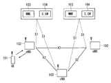
- the overall architecture will be described with reference to FIG.
- FIG. 1 is an explanatory diagram illustrating a configuration of an LTE communication system.
- a control protocol for the mobile terminal 101 such as RRC (Radio Resource Control) and a user plane such as PDCP (Packet Data Convergence Protocol), RLC (Radio Link Control), MAC (Medium Access Control), PHY (Physical Layer)
- RRC Radio Resource Control
- PDCP Packet Data Convergence Protocol
- RLC Radio Link Control
- MAC Medium Access Control
- PHY Physical Layer
- the base station 102 performs scheduling (scheduling) and transmission of a paging signal (also called paging signal or paging message) notified from a mobility management entity (MME) 103.
- Base stations 102 are connected to each other via an X2 interface.
- the base station 102 is connected to an EPC (Evolved Packet Core) via an S1 interface. More specifically, the base station 102 is connected to an MME (Mobility Management Entity) 103 via an S1_MME interface, and is connected to an S-GW (Serving Gateway) 104 via an S1_U interface.
- EPC Evolved Packet Core
- MME Mobility Management Entity
- S-GW Serving Gateway
- the MME 103 distributes a paging signal to a plurality or a single base station 102. Further, the MME 103 performs mobility control (Mobility control) in a standby state (Idle State). The MME 103 manages a tracking area (Tracking Area) list when the mobile terminal is in a standby state and in an active state (Active State).
- Mobility control mobility control
- Idle State standby state
- the MME 103 manages a tracking area (Tracking Area) list when the mobile terminal is in a standby state and in an active state (Active State).
- the S-GW 104 transmits / receives user data to / from one or a plurality of base stations 102.
- the S-GW 104 becomes a local mobility anchor point (Mobility Anchor Point) during handover between base stations.
- EPC further includes P-GW (PDN Gateway).
- P-GW PDN Gateway
- the control protocol RRC between the mobile terminal 101 and the base station 102 performs broadcast, paging, RRC connection management (RRC connection management), and the like.
- RRC_IDLE and RRC_CONNECTED are states between the base station and the mobile terminal in RRC.
- RRC_IDLE PLMN (Public Land Mobile Mobile Network) selection, system information (System Information: SI) notification, paging, cell re-selection, mobility, and the like are performed.
- RRC_CONNECTED the mobile terminal has an RRC connection and can send and receive data to and from the network.
- handover Handover (Handover: HO), measurement of a neighbor cell (Neighbour cell), and the like are performed.
- Non-Patent Document 1 (Chapter 5), 3GPP determination items related to the frame configuration in the LTE system will be described with reference to FIG.
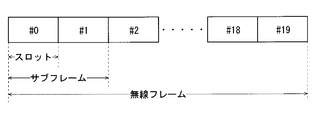
- FIG. 2 is an explanatory diagram showing a configuration of a radio frame used in the LTE communication system.
- one radio frame (Radio frame) is 10 ms.
- the radio frame is divided into ten equally sized subframes.
- the subframe is divided into two equally sized slots.
- a downlink synchronization signal (Downlink Synchronization Signal: SS) is included in the first and sixth subframes for each radio frame.
- the synchronization signal includes a first synchronization signal (Primary Synchronization Signal: P-SS) and a second synchronization signal (Secondary Synchronization Signal: S-SS).
- MBSFN transmission is a simultaneous broadcast transmission technology (simulcast transmission technique) realized by transmitting the same waveform from a plurality of cells at the same time.
- MBSFN transmission from a plurality of cells in the MBSFN area is recognized as one transmission by the mobile terminal.
- the MBSFN is a network that supports such MBSFN transmission.
- a subframe for MBSFN transmission is referred to as an MBSFN subframe (MBSFN subframe).
- Non-Patent Document 2 describes a signaling example at the time of MBSFN subframe allocation.
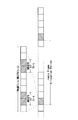
- FIG. 3 is an explanatory diagram showing the configuration of the MBSFN frame.
- a radio frame including an MBSFN subframe is allocated every allocation period (radio frame allocation period).
- the MBSFN subframe is a subframe allocated for MBSFN in a radio frame defined by an allocation period and an allocation offset (radio frame allocation offset), and is a subframe for transmitting multimedia data.
- a radio frame satisfying the following expression (1) is a radio frame including an MBSFN subframe.
- SFN mod radioFrameAllocationPeriod radioFrameAllocationOffset (1)
- MBSFN subframe allocation is performed with 6 bits.
- the leftmost bit in FIG. 3 defines the second (# 1) MBSFN allocation of the subframe.
- the second bit from the left is the third (# 2) of the subframe, the third bit from the left is the fourth (# 3) of the subframe, and the fourth bit from the left is the seventh (# 6) of the subframe.
- the fifth bit from the left defines the eighth (# 7) MBSFN allocation of the subframe, and the sixth bit from the left defines the ninth (# 8) MBSFN allocation of the subframe.
- the bit indicates “1”, it indicates that the corresponding subframe is allocated for MBSFN.
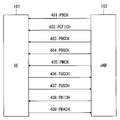
- Non-Patent Document 1 (Chapter 5) describes the decision items regarding the channel configuration in the LTE system in 3GPP. It is assumed that the same channel configuration as that of the non-CSG cell is used in a CSG (Closed Subscriber Group) cell. A physical channel will be described with reference to FIG. FIG. 4 is an explanatory diagram illustrating physical channels used in the LTE communication system.
- a physical broadcast channel (PBCH) 401 is a channel for downlink transmission from the base station 102 to the mobile terminal 101.
- a BCH transport block (transport block) is mapped to four subframes in a 40 ms interval. There is no obvious signaling of 40ms timing.
- a physical control channel format indicator channel (Physical Control Format Indicator Channel: PCFICH) 402 is a channel for downlink transmission from the base station 102 to the mobile terminal 101.
- PCFICH notifies base station 102 to mobile terminal 101 about the number of OFDM symbols used for PDCCHs.
- PCFICH is transmitted for each subframe.
- a physical downlink control channel (Physical Downlink Control Channel: PDCCH) 403 is a channel for downlink transmission from the base station 102 to the mobile terminal 101.
- the PDCCH is one of the transport channels shown in FIG. 5 described later, and is one of the transport channels shown in FIG. 5 and resource allocation information of a downlink shared channel (DL-SCH) that is one of the transport channels shown in FIG. It reports resource allocation (allocation) information of a certain paging channel (Paging-Channel: PCH) and HARQ (Hybrid-Automatic-Repeat-reQuest) information regarding DL-SCH.
- the PDCCH carries an uplink scheduling grant (Uplink Scheduling Grant).
- the PDCCH carries Ack (Acknowledgement) / Nack (Negative Acknowledgment) which is a response signal for uplink transmission.
- the PDCCH is also called an L1 / L2 control signal.
- a physical downlink shared channel (PDSCH) 404 is a channel for downlink transmission from the base station 102 to the mobile terminal 101.
- a downlink shared channel (DL-SCH) that is a transport channel and PCH that is a transport channel are mapped.
- a physical multicast channel (PMCH) 405 is a channel for downlink transmission from the base station 102 to the mobile terminal 101.
- a multicast channel (Multicast Channel: MCH) that is a transport channel is mapped to the PMCH.
- a physical uplink control channel (Physical Uplink Control Channel: PUCCH) 406 is a channel for uplink transmission from the mobile terminal 101 to the base station 102.
- the PUCCH carries Ack / Nack which is a response signal (response signal) for downlink transmission.
- the PUCCH carries a CQI (Channel Quality Indicator) report.
- CQI is quality information indicating the quality of received data or channel quality.
- the PUCCH carries a scheduling request (SR).
- SR scheduling request
- a physical uplink shared channel (PUSCH) 407 is a channel for uplink transmission from the mobile terminal 101 to the base station 102.
- An uplink shared channel (Uplink Shared Channel: UL-SCH) that is one of the transport channels shown in FIG. 5 is mapped to the PUSCH.
- the physical HARQ indicator channel (Physical Hybrid ARQ Indicator Channel: PHICH) 408 is a channel for downlink transmission from the base station 102 to the mobile terminal 101.
- PHICH carries Ack / Nack which is a response signal for uplink transmission.
- a physical random access channel (Physical Random Access Channel: PRACH) 409 is a channel for uplink transmission from the mobile terminal 101 to the base station 102.
- the PRACH carries a random access preamble.
- the downlink reference signal (Reference signal: RS) is a symbol known as a mobile communication system.
- the following five types of downlink reference signals are defined.
- Cell-specific reference signals Cell-specific Reference Signals: CRS
- MBSFN reference signals MBSFN reference signals
- UE-specific reference signals UE-specific reference signals
- Data demodulation reference signals Demodulation Reference Signals: DM-RS
- Position determination reference signals Position determination reference signals
- PRS Position determination reference signals
- Channel information reference signals Channel-State Information Reference Signals: CSI-RS.
- RSRP reference signal received power
- FIG. 5 is an explanatory diagram for explaining a transport channel used in an LTE communication system.
- FIG. 5A shows the mapping between the downlink transport channel and the downlink physical channel.
- FIG. 5B shows mapping between the uplink transport channel and the uplink physical channel.
- a broadcast channel (Broadcast Channel: BCH) is broadcast to the entire coverage of the base station (cell).
- BCH is mapped to the physical broadcast channel (PBCH).
- HARQ Hybrid ARQ
- DL-SCH downlink shared channel
- the DL-SCH can be broadcast to the entire coverage of the base station (cell).
- DL-SCH supports dynamic or semi-static resource allocation. Quasi-static resource allocation is also referred to as persistent scheduling.
- DL-SCH supports discontinuous reception (DRX) of a mobile terminal in order to reduce power consumption of the mobile terminal.
- the DL-SCH is mapped to the physical downlink shared channel (PDSCH).
- the Paging Channel supports DRX of the mobile terminal in order to enable low power consumption of the mobile terminal.
- the PCH is required to be broadcast to the entire coverage of the base station (cell).
- the PCH is mapped to a physical resource such as a physical downlink shared channel (PDSCH) that can be dynamically used for traffic.
- PDSCH physical downlink shared channel
- a multicast channel (Multicast Channel: MCH) is used for broadcasting to the entire coverage of a base station (cell).
- the MCH supports SFN combining of MBMS services (MTCH and MCCH) in multi-cell transmission.
- the MCH supports quasi-static resource allocation.
- MCH is mapped to PMCH.
- HARQ Hybrid ARQ
- UL-SCH Uplink Shared Channel
- PUSCH physical uplink shared channel
- the random access channel (Random Access Channel: RACH) shown in FIG. 5B is limited to control information. RACH is at risk of collision.
- RACH is mapped to a physical random access channel (PRACH).
- PRACH physical random access channel
- HARQ is a technique for improving the communication quality of a transmission path by combining an automatic repeat request (AutomaticAutoRepeat reQuest: ARQ) and error correction (Forward Error Correction).
- ARQ automatic repeat request
- FEC Correction Forward Error Correction
- HARQ has an advantage that error correction functions effectively by retransmission even for a transmission path whose communication quality changes. In particular, further quality improvement can be obtained by combining the initial transmission reception result and the retransmission reception result upon retransmission.
- Chase combining is a method of transmitting the same data in initial transmission and retransmission, and is a method of improving gain by combining initial transmission data and retransmission data in retransmission.
- Chase combining includes data that is partially accurate even if there is an error in the initial transmission data. Is based on the idea that can be sent.
- Another example of the HARQ method is IR (Incremental Redundancy). IR is to increase the redundancy, and by transmitting parity bits in retransmission, the redundancy is increased in combination with the initial transmission, and the quality is improved by the error correction function.
- FIG. 6 is an explanatory diagram illustrating logical channels used in the LTE communication system.
- FIG. 6A shows mapping between the downlink logical channel and the downlink transport channel.
- FIG. 6B shows mapping between the uplink logical channel and the uplink transport channel.
- Broadcast Control Channel is a downlink channel for broadcast system control information.
- the BCCH that is a logical channel is mapped to a broadcast channel (BCH) that is a transport channel or a downlink shared channel (DL-SCH).
- BCH broadcast channel
- DL-SCH downlink shared channel
- the paging control channel (Paging Control Channel: PCCH) is a downlink channel for transmitting changes in paging information (Paging Information) and system information (System Information).
- PCCH is used when the network does not know the cell location of the mobile terminal.
- the PCCH that is a logical channel is mapped to a paging channel (PCH) that is a transport channel.
- PCH paging channel
- the common control channel (Common Control Channel: CCCH) is a channel for transmission control information between the mobile terminal and the base station. CCCH is used when the mobile terminal does not have an RRC connection with the network.
- CCCH is mapped to a downlink shared channel (DL-SCH) that is a transport channel.
- DL-SCH downlink shared channel
- UL-SCH uplink shared channel
- the multicast control channel (Multicast Control Channel: MCCH) is a downlink channel for one-to-many transmission.
- the MCCH is used for transmission of MBMS control information for one or several MTCHs from the network to the mobile terminal.
- MCCH is used only for mobile terminals that are receiving MBMS.
- the MCCH is mapped to a multicast channel (MCH) that is a transport channel.
- the dedicated control channel (Dedicated Control Channel: DCCH) is a channel for transmitting individual control information between the mobile terminal and the network on a one-to-one basis.
- DCCH is used when the mobile terminal is in RRC connection.
- the DCCH is mapped to the uplink shared channel (UL-SCH) in the uplink, and is mapped to the downlink shared channel (DL-SCH) in the downlink.
- the dedicated traffic channel (Dedicated Traffic Channel: DTCH) is a channel for one-to-one communication to individual mobile terminals for transmitting user information.
- DTCH exists for both uplink and downlink.
- the DTCH is mapped to the uplink shared channel (UL-SCH) in the uplink, and is mapped to the downlink shared channel (DL-SCH) in the downlink.
- UL-SCH uplink shared channel
- DL-SCH downlink shared channel
- the multicast traffic channel is a downlink channel for transmitting traffic data from the network to the mobile terminal.
- MTCH is a channel used only for a mobile terminal that is receiving MBMS.
- the MTCH is mapped to a multicast channel (MCH).
- CGI is a Cell Global Identification.
- ECGI is an E-UTRAN cell global identifier (E-UTRAN Cell Global Identification).
- LTE Long Term Evolution Advanced
- UMTS Universal Mobile Telecommunication System
- CSG Cell Subscriber Group
- a CSG (Closed Subscriber Group) cell is a cell in which an operator identifies an available subscriber (hereinafter, may be referred to as a “specific subscriber cell”).
- Identified subscribers are allowed to access one or more cells of the PLMN (Public Land Mobile Mobile Network).
- PLMN Public Land Mobile Mobile Network
- One or more cells to which the identified subscribers are allowed access are called “CSG cells (CSG cell (s))”.
- CSG cell (s) the cells to which the identified subscribers are allowed access.
- PLMN has access restrictions.
- the CSG cell is a part of the PLMN that broadcasts a unique CSG identity (CSG identity: CSG ID; CSG-ID) and “TRUE” via CSG indication (CSG indication).
- CSG identity CSG ID; CSG-ID
- CSG indication CSG indication
- the CSG-ID is broadcast by the CSG cell or cell. There are a plurality of CSG-IDs in a mobile communication system. The CSG-ID is then used by the mobile terminal (UE) to facilitate access of CSG related members.
- the location tracking of the mobile terminal is performed in units of areas composed of one or more cells.
- the position tracking is performed to track the position of the mobile terminal and call the mobile terminal even in the standby state, in other words, to enable the mobile terminal to receive a call.
- This area for tracking the location of the mobile terminal is called a tracking area.
- the CSG white list (CSG White List) is a list that may be stored in a USIM (Universal Subscriber Identity Module) in which all CSG IDs of CSG cells to which a subscriber belongs are recorded.
- the CSG white list may be simply referred to as a white list or an allowed CSG list (Allowed CSG List).
- the MME performs access control (refer to non-patent document 9, 4.3.1.2).
- Specific examples of mobile terminal access include attach (attach), combined attach (combined ⁇ attach), detach (detach), service request (service request), tracking area update procedure (Tracking Area Update procedure), etc. (Refer to Chapter 9, 4.3.1.2).
- Non-Patent Document 3 Chapter 4.3
- a service type of a mobile terminal in a standby state there are a limited service (also referred to as a limited service), a standard service (normal service (Normal service)), and an operator service (Operator service).
- the restricted services are emergency calls (Emergency calls), ETWS (Earthquake and Tsunami warning systems), and CMAS (Commercial Mobile Alert Systems), which will be described later.
- a standard service also called a normal service
- the operator service is a service only for an operator on a reserve cell to be described later.
- Suitable cell is described below.
- a “suitable cell” is a cell that the UE may camp on (Camp ON) to receive normal service. Such a cell shall satisfy the following conditions (1) and (2).
- the cell is a selected PLMN or a registered PLMN, or a part of the PLMN in the “Equivalent PLMN list”.
- the latest information provided by NAS must satisfy the following conditions (a) to (d).
- SI system information
- Acceptable cell is a cell in which a UE may camp on to receive limited services. Such a cell shall satisfy all the following requirements (1) and (2).
- the cell is not a forbidden cell (also referred to as “Barred cell”). (2) The cell satisfies the cell selection evaluation criteria.
- Barred cell is indicated by system information. “Reserved cell” is instructed by system information.
- “Cam camp on cell” means that the UE has completed cell selection or cell reselection processing and the UE selects a cell for monitoring system information and paging information It means to become a state.
- a cell where the UE camps on may be referred to as a “serving cell”.
- Non-Patent Document 4 discloses three different modes of access to HeNB and HNB. Specifically, an open access mode (Open access mode), a closed access mode (Closed access mode), and a hybrid access mode (Hybrid access mode) are disclosed.
- Open access mode Open access mode
- closed access mode closed access mode
- Hybrid access mode Hybrid access mode
- Each mode has the following characteristics.
- the HeNB and HNB are operated as normal cells of a normal operator.
- the closed access mode the HeNB and HNB are operated as CSG cells.
- This CSG cell is a CSG cell accessible only to CSG members.
- the hybrid access mode the HeNB and HNB are operated as CSG cells in which non-CSG members are also allowed to access at the same time.
- a hybrid access mode cell (also referred to as a hybrid cell) is a cell that supports both an open access mode and a closed access mode.
- PCI range reserved by the network for use in the CSG cell among all PCI (Physical Cell Identity) (see non-patent document 1, chapter 10.5.1.1). Dividing the PCI range may be referred to as PCI split.
- Information on the PCI split (also referred to as PCI split information) is reported from the base station to the mobile terminals being served by the system information. Being served by a base station means that the base station is a serving cell.
- Non-Patent Document 5 discloses a basic operation of a mobile terminal using PCI split.
- a mobile terminal that does not have PCI split information needs to perform cell search using all PCIs, for example, using all 504 codes.
- a mobile terminal having PCI split information can perform a cell search using the PCI split information.
- LTE-A Long Term Evolution Advanced
- a relay node that is a relay device is wirelessly connected to a radio access network via a cell called a donor cell (hereinafter referred to as “donor eNB (Denor eNB)”).
- donor eNB Denor eNB
- the link from the network (NW) to the relay node shares the same frequency band (frequency band) as the link from the network to the UE.
- a UE compatible with Release 8 of 3GPP can be connected to the donor cell.
- the link between the donor cell and the relay node is referred to as a backhaul link, and the link between the relay node and the UE is referred to as an access link.
- transmission from DeNB to RN is performed in a downlink (DL) frequency band
- transmission from RN to DeNB is performed in an uplink (UL) frequency band.
- DL downlink
- UL uplink
- a link from DeNB to RN and a link from RN to UE are time-division multiplexed in one frequency band
- a link from RN to DeNB and a link from UE to RN are also one frequency band. Is time-division multiplexed. By doing so, it is possible to prevent the relay transmission from interfering with the reception of the own relay in the relay.
- eNB macro cell
- pico eNB pico cell
- HeNB HeNB
- CSG cell HeNB
- RRH Remote Radio Head
- So-called local nodes such as repeaters are being studied.
- a network composed of various types of cells as described above is sometimes referred to as a heterogeneous network.
- Non-Patent Document 8 describes the frequency band.
- CC Component Carrier
- aggregation In the LTE-A system, two or more component carriers (Component Carrier: CC) are aggregated (also referred to as aggregation) in order to support a wider frequency bandwidth (transmission bandwidths) up to 100 MHz. Aggregation (CA) is being studied.
- CA Aggregation
- a 3GPP-compatible UE corresponding to Release 8 or 9 that is LTE-compatible can transmit and receive only on one CC corresponding to one serving cell.
- a 3GPP Release 10 compliant UE may have a capability (capability) for simultaneous transmission / reception, reception only, or transmission only on a plurality of CCs corresponding to a plurality of serving cells. It is considered.
- Each CC uses a 3GPP Release 8 or 9 configuration, and the CA supports continuous CCs, non-continuous CCs, and CCs with different frequency bandwidths. It is impossible for the UE to configure an uplink CC (UL CC) that is equal to or greater than the number of downlink CCs (DL CCs). CCs configured from the same eNB need not provide the same coverage. CC is compatible with 3GPP Release 8 or 9.
- CA there is one independent HARQ entity for each serving cell for both uplink and downlink.
- a transport block is generated for each TTI for each serving cell.
- Each transport block and HARQ retransmission are mapped to a single serving cell.
- UE When CA is configured, UE has only one RRC connection (RRC connection) with NW.
- RRC connection In the RRC connection, one serving cell provides NAS mobility information and security input. This cell is referred to as a primary cell (PCell).
- a carrier corresponding to PCell is a downlink primary component carrier (Downlink Primary Component Carrier: DL PCC).
- the carrier corresponding to the PCell in the uplink is an uplink primary component carrier (Uplink Primary Component Carrier: UL PCC).
- a secondary cell (Secondary Cell: SCell) is configured to form a set of a PCell and a serving cell.
- the carrier corresponding to the SCell in the downlink is a downlink secondary component carrier (Downlink Secondary Component Carrier: DL SCC).
- the carrier corresponding to the SCell in the uplink is an uplink secondary component carrier (Uplink Secondary Component Carrier: UL SCC).
- a set of one PCell and a serving cell composed of one or more SCells is configured for one UE.
- LTE-A LTE Advanced
- Non-Patent Document 6 and Non-Patent Document 7 LTE Advanced
- New technologies include a technology that supports a wider bandwidth (Wider bandwidth extension), and a coordinated ⁇ ⁇ ⁇ Multiple Point transmission and reception (CoMP) technology.
- CoMP being studied for LTE-A by 3GPP is described in Non-Patent Document 6 and Non-Patent Document 7.
- CoMP is a technology that aims to expand coverage at a high data rate, improve throughput at the cell edge, and increase throughput in a communication system by performing coordinated transmission or reception between geographically separated multipoints. is there.
- CoMP includes downlink CoMP (DL CoMP) and uplink CoMP (UL CoMP).
- PDSCH to one mobile terminal is transmitted in cooperation between multiple points (multipoint).
- the PDSCH for one UE may be transmitted from one point of the multipoint or may be transmitted from a plurality of points of the multipoint.
- a serving cell is a single cell that transmits resource allocation through PDCCH.
- JP joint processing
- CS coordinated scheduling
- CB coordinated beamforming
- JP can use data at each point in the CoMP cooperating set.
- JP includes joint transmission (Joint Transmission: JT) and dynamic cell selection (Dynamic Cell Selection: DCS).
- JT Joint Transmission
- DCS Dynamic Cell Selection
- JT PDSCH is transmitted from a plurality of points at a certain point in time, specifically, from a part or all of a CoMP cooperating set.
- DCS PDSCH is transmitted from one point in the CoMP cooperating set at a certain point in time.
- CS / CB can only be used for data transmission from the serving cell.
- user scheduling or beamforming is determined together with adjustment between cells corresponding to the CoMP cooperating set.
- a base station (NB, eNB, HNB, HeNB), RRU (Remote Radio Unit), RRE (Remote Radio Equipment), RRH (Remote Radio Head), relay node (Relay Node: RN) ) Etc.
- NB base station
- eNB eNB
- HNB HeNB
- RRU Remote Radio Unit
- RRE Remote Radio Equipment
- RRH Remote Radio Head
- relay node Relay Node: RN
- fixed RN fixed RN
- mobile RN mobile relay, mobile RN
- the source DeNB when the RN moves and the HO is activated, the source DeNB does not recognize which cell can support the RN, and thus cannot select an appropriate destination cell. Therefore, the source DeNB cannot HO the RN, causing HO failure and further disconnection of communication. In addition, even if the RN can HO to the destination DeNB, if another RN exists in the vicinity of the RN, there is a problem that communication cannot be performed due to interference with the other RN.
- a problem occurs not only in the function as the UE in the RN but also in the function as the eNB.
- a problem occurs not only in the function as the UE in the RN but also in the function as the eNB.
- a handover to an eNB operated in a frequency or frequency band different from that of the source DeNB hereinafter, sometimes referred to as “different frequency handover (HO)”
- HO different frequency handover
- An object of the present invention is to provide a mobile communication system capable of continuing communication between a mobile terminal device and a base station device via a relay device even when the relay device moves.
- the mobile communication system of the present invention includes a mobile terminal device that can move, a plurality of base station devices that can wirelessly communicate with the mobile terminal device, and is configured to be movable between the mobile terminal device and the base station device. And a relay device that relays wireless communication between the base station device to which the relay device is connected from the source base station device to the destination as the relay device moves.
- the destination base station apparatus rejects a connection request from the relay apparatus when the base station apparatus does not have a function corresponding to the relay apparatus. To do.
- the mobile communication system of the present invention includes a mobile terminal device that can move, a plurality of base station devices that can wirelessly communicate with the mobile terminal device, and a mobile device that can move, the mobile terminal device and the base station device,
- a mobile communication system comprising a relay device that relays wireless communication between the base station device to which the relay device is connected from the source base station device when the relay device moves.
- the source base station device selects the destination base station device from among base station devices other than the base station device that does not have a function corresponding to the relay device.
- the handover process is executed so that the relay device is connected to the selected base station device.
- the destination base station device when the destination base station device does not have a function corresponding to the relay device, the destination base station device rejects the connection request from the relay device.
- the relay apparatus can return to the connection with the base station apparatus of the movement source or select another base station apparatus as the connection destination, so that the connection with the base station apparatus can be continued. it can. Therefore, even when the relay device moves, communication can be continued between the relay device and the base station device, so that a communication service to the mobile terminal device being served by the relay device can be continued.
- the base station apparatus of the movement destination is selected from the base station apparatuses other than the base station apparatus that does not have a function corresponding to the relay apparatus by the base station apparatus of the movement source,
- the handover process is executed so that the relay device is connected to the selected base station device.
- a base station device having no function corresponding to the relay device is used as a destination base station device from being activated.
- handover processing in which a base station device that does not have a function corresponding to a relay device is a destination base station device is always rejected because the destination base station device does not have a function corresponding to the relay device. Is.
- the processing load of the entire mobile communication system can be reduced.
- control delay can be prevented.
- FIG. 2 is an explanatory diagram showing a configuration of a radio frame used in an LTE communication system. It is explanatory drawing which shows the structure of a MBSFN frame. It is explanatory drawing explaining the physical channel used with the communication system of a LTE system. It is explanatory drawing explaining the transport channel used with the communication system of a LTE system. It is explanatory drawing explaining the logical channel used with the communication system of a LTE system.
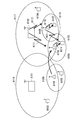
- 1 is a block diagram showing an overall configuration of an LTE mobile communication system discussed in 3GPP.
- FIG. It is a block diagram which shows the structure of the mobile terminal 71 shown in FIG. 7 which is a mobile terminal which concerns on this invention.
- FIG. 7 It is a block diagram which shows the structure of the base station 72 shown in FIG. 7 which is a base station which concerns on this invention. It is a block diagram which shows the structure of the MME part 73 shown in FIG. 7 which is MME which concerns on this invention. It is a block diagram which shows the structure of HeNBGW74 shown in FIG. 7 which is HeNBGW which concerns on this invention.
- 5 is a flowchart illustrating an outline from a cell search to a standby operation performed by a mobile terminal (UE) in an LTE communication system.
- FIG. 2 is a diagram showing an architecture of a mobile communication system with RN in Release 10 of 3GPP. It is a figure for demonstrating the use case (use example) of mobile RN.
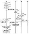
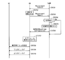
- FIG. 2 It is a figure which shows an example of the sequence of the mobile communication system in the modification 2 of Embodiment 1.
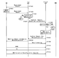
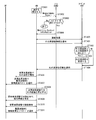
- FIG. It is a figure which shows an example of the sequence of the mobile communication system in the modification 3 of Embodiment 1.
- FIG. It is a figure which shows an example of the sequence of the mobile communication system in the modification 3 of Embodiment 1.
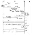
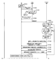
- FIG. It is a figure which shows an example of the sequence of the mobile communication system in the modification 4 of Embodiment 1.
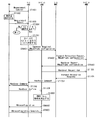
- FIG. It is a figure which shows an example of the sequence of the mobile communication system in the modification 5 of Embodiment 1.
- FIG. It is a figure which shows an example of the sequence of the mobile communication system in the modification 5 of Embodiment 1.
- FIG. It is a figure which shows an example of the sequence of the mobile communication system in the modification 5 of Embodiment 1.
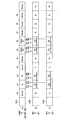
- FIG. 1 It is a figure which shows the architecture of a mobile communication system when RN exists under DeNB's umbrella. It is a figure which shows the structural example of the subframe of the downlink in FDD when RN1304 and UE2901 exist under DeNB1305 umbrella. It is a figure which shows the structural example of the uplink sub-frame in FDD when RN1304 and UE2901 exist under DeNB1305 umbrella. It is a figure which shows an example of the sequence of the mobile communication system in the modification 6 of Embodiment 1. FIG. It is a figure which shows an example of the sequence of the mobile communication system in the modification 6 of Embodiment 1. FIG. It is a figure which shows an example of the sequence of the mobile communication system in the modification 6 of Embodiment 1. FIG. It is a figure which shows an example of the sequence of the mobile communication system in the modification 6 of Embodiment 1. FIG.
- FIG. 6 It is a figure which shows an example of the sequence of the mobile communication system in the modification 6 of Embodiment 1.
- FIG. 7 shows an example of the sequence of the mobile communication system in Embodiment 1.
- FIG. It is a figure which shows an example of the sequence of the mobile communication system in Embodiment 2.
- FIG. It is a figure which shows an example of the sequence of the mobile communication system in the modification 1 of Embodiment 2.
- FIG. It is a figure which shows an example of the sequence of the mobile communication system in the modification 2 of Embodiment 2.
- FIG. It is a figure which shows an example of the sequence of the mobile communication system in the modification 3 of Embodiment 2.
- FIG. 10 is a diagram showing an exemplary sequence of a mobile communication system in a third embodiment.
- FIG. 10 is a diagram showing an exemplary sequence of a mobile communication system in a third embodiment.
- FIG. 10 is a diagram showing an exemplary sequence of a mobile communication system in a third embodiment.
- FIG. 10 is a diagram showing an exemplary sequence of a mobile communication system in a third embodiment.
- FIG. 10 is a diagram showing an exemplary sequence of a mobile communication system in a third embodiment.
- FIG. 10 is a diagram showing an exemplary sequence of a mobile communication system in a third embodiment. It is a figure which shows the structural example of the sub-frame of a downlink when the RN sub-frame structure of RN where interference becomes a problem is made the same. It is a figure which shows the structural example of the uplink sub-frame at the time of making the RN sub-frame structure of RN where interference becomes a problem into the same.
- FIG. 10 is a diagram showing an exemplary sequence of a mobile communication system in a third embodiment.
- It is a figure which shows the structural example of the sub-frame of a downlink when the RN sub-frame structure of RN where interference becomes a problem is made the
- FIG. 11 is a diagram showing an exemplary sequence of a mobile communication system in a first modification of the third embodiment. It is a figure which shows the structural example of the frequency of the backhaul link and access link in the modification 2 of Embodiment 3.
- FIG. 11 is a diagram showing an exemplary sequence of a mobile communication system in a second modification of the third embodiment.
- FIG. 11 is a diagram showing an exemplary sequence of a mobile communication system in a second modification of the third embodiment.
- FIG. 11 is a diagram showing an exemplary sequence of a mobile communication system in a second modification of the third embodiment.
- FIG. 23 is a diagram showing an exemplary sequence of a mobile communication system in a third modification of the third embodiment.
- FIG. 23 is a diagram showing an exemplary sequence of a mobile communication system in a third modification of the third embodiment. It is a figure for demonstrating the interference which arises between RN which moved and the existing RN. It is a figure for demonstrating the interference which arises between RN which moved and the existing RN. It is a figure which shows the structural example of the sub-frame of a downlink when the sub-frame of an access link differs between RN. It is a figure which shows the structural example of the subframe of an uplink at the time of changing the subframe of an access link between RN.
- FIG. 10 is a diagram showing an exemplary sequence of a mobile communication system in a fourth embodiment.
- FIG. 10 is a diagram showing an exemplary sequence of a mobile communication system in a first modification of the fourth embodiment.
- FIG. 10 is a diagram showing an exemplary sequence of a mobile communication system in a first modification of the fourth embodiment. It is a figure for demonstrating the change of the signal to interference ratio (SIR) of the access link in UE served by each RN when RN approaches. It is a figure for demonstrating the change of the signal to interference ratio (SIR) of the access link in UE served by each RN when RN approaches.
- SIR signal to interference ratio
- FIG. 10 is a diagram showing an exemplary sequence of a mobile communication system in a fifth embodiment.
- FIG. 38 is a diagram showing an exemplary sequence of a mobile communication system in a first modification of the fifth embodiment.
- FIG. 38 is a diagram showing an exemplary sequence of a mobile communication system in a first modification of the fifth embodiment. It is a figure which shows the specific example of the data managed within a server. It is a figure which shows the architecture of the mobile communication system in Embodiment 6 including the node which has the function of RN and the function of HeNB.
- FIG. 38 shows an exemplary sequence of a mobile communication system in a seventh embodiment.
- FIG. 38 shows an exemplary sequence of a mobile communication system in a first modification of the seventh embodiment.
- FIG. 7 is a block diagram showing an overall configuration of an LTE mobile communication system discussed in 3GPP.
- CSG Cell Subscriber Group
- E-UTRAN Home-eNodeB Home-eNB; HeNB
- UTRAN Home-NB HNB
- non-CSG cells E-UTRAN eNodeB (eNB)
- NB UTRAN NodeB
- GERAN BSS GERAN BSS
- a mobile terminal device (hereinafter referred to as “user terminal (UE)”) 71 is capable of wireless communication with a base station device (hereinafter referred to as “base station”) 72 and transmits and receives signals by wireless communication.
- the base station 72 is classified into an eNB 72-1 that is a macro cell and a Home-eNB 72-2 that is a local node.
- the eNB 72-1 has a relatively large large-scale coverage as a coverage that can be communicated with the mobile terminal (UE) 71.
- the Home-eNB 72-2 has a relatively small small-scale coverage.
- the eNB 72-1 is connected to the MME, S-GW, or the MME / S-GW unit (hereinafter also referred to as “MME unit”) 73 including the MME and S-GW through the S 1 interface. Control information is communicated with the unit 73.
- MME unit 73 A plurality of MME units 73 may be connected to one eNB 72-1.
- the MME unit 73 corresponds to management means.
- the MME unit 73 is included in an EPC that is a core network.
- the eNBs 72-1 are connected by the X2 interface, and control information is communicated between the eNBs 72-1.
- the Home-eNB 72-2 is connected to the MME unit 73 via the S1 interface, and control information is communicated between the Home-eNB 72-2 and the MME unit 73.
- a plurality of Home-eNBs 72-2 are connected to one MME unit 73.
- the Home-eNB 72-2 is connected to the MME unit 73 via a HeNBGW (Home-eNB GateWay) 74.
- Home-eNB 72-2 and HeNBGW 74 are connected via an S1 interface, and HeNBGW 74 and MME unit 73 are connected via an S1 interface.
- One or more Home-eNBs 72-2 are connected to one HeNBGW 74, and information is communicated through the S1 interface.
- the HeNBGW 74 is connected to one or a plurality of MME units 73, and information is communicated through the S1 interface.
- the MME unit 73 and the HeNBGW 74 are higher-level node devices, and control connection between the eNB 72-1 and Home-eNB 72-2, which are base stations, and a mobile terminal (UE) 71.
- the MME unit 73, specifically, the MME and S-GW, and the HeNBGW 74 configuring the MME unit 73 correspond to management means.
- the MME unit 73 and the HeNBGW 74 are included in an EPC that is a core network.
- the X2 interface between Home-eNB 72-2 is supported. That is, the Home-eNB 72-2 is connected by the X2 interface, and control information is communicated between the Home-eNB 72-2. From the MME unit 73, the HeNBGW 74 appears as a Home-eNB 72-2. From the Home-eNB 72-2, the HeNBGW 74 appears as the MME unit 73.
- the interface between the Home-eNB 72-2 and the MME unit 73 is , S1 interface is the same.
- the HeNBGW 74 does not support mobility to the Home-eNB 72-2 or mobility from the Home-eNB 72-2 that spans a plurality of MME units 73.
- the Home-eNB 72-2 configures and supports a single cell.
- the base station apparatus supports a single cell such as Home-eNB 72-2, but is not limited to this, and one base station apparatus may support a plurality of cells. When one base station apparatus supports a plurality of cells, each cell functions as a base station apparatus.
- FIG. 8 is a block diagram showing a configuration of the mobile terminal 71 shown in FIG. 7 which is a mobile terminal according to the present invention.
- a transmission process of the mobile terminal 71 shown in FIG. 8 will be described.
- control data from the protocol processing unit 801 and user data from the application unit 802 are stored in the transmission data buffer unit 803.
- the data stored in the transmission data buffer unit 803 is transferred to the encoder unit 804 and subjected to encoding processing such as error correction.
- the data encoded by the encoder unit 804 is modulated by the modulation unit 805.
- the modulated data is converted into a baseband signal, and then output to the frequency conversion unit 806, where it is converted into a radio transmission frequency.
- a transmission signal is transmitted from the antenna 807 to the base station 72.
- the reception process of the mobile terminal 71 is executed as follows.
- a radio signal from the base station 72 is received by the antenna 807.
- the reception signal is converted from a radio reception frequency to a baseband signal by the frequency conversion unit 806, and demodulated by the demodulation unit 808.
- the demodulated data is passed to the decoder unit 809 and subjected to decoding processing such as error correction.
- control data is passed to the protocol processing unit 801, and user data is passed to the application unit 802.
- a series of processing of the mobile terminal 71 is controlled by the control unit 810. Therefore, the control unit 810 is connected to the respective units 801 to 809, which is omitted in FIG.
- FIG. 9 is a block diagram showing a configuration of the base station 72 shown in FIG. 7 which is a base station according to the present invention.
- the transmission process of the base station 72 shown in FIG. 9 will be described.
- the EPC communication unit 901 transmits and receives data between the base station 72 and the EPC (MME unit 73, HeNBGW 74, etc.).
- the other base station communication unit 902 transmits / receives data to / from other base stations.
- the EPC communication unit 901 and the other base station communication unit 902 exchange information with the protocol processing unit 903, respectively. Control data from the protocol processing unit 903 and user data and control data from the EPC communication unit 901 and the other base station communication unit 902 are stored in the transmission data buffer unit 904.
- the data stored in the transmission data buffer unit 904 is transferred to the encoder unit 905 and subjected to encoding processing such as error correction. There may exist data that is directly output from the transmission data buffer unit 904 to the modulation unit 906 without performing the encoding process.
- the encoded data is subjected to modulation processing by the modulation unit 906.
- the modulated data is converted into a baseband signal, and then output to the frequency conversion unit 907 to be converted into a radio transmission frequency. Thereafter, a transmission signal is transmitted from the antenna 908 to one or a plurality of mobile terminals 71.
- the reception process of the base station 72 is executed as follows. Radio signals from one or a plurality of mobile terminals 71 are received by the antenna 908. The reception signal is converted from a radio reception frequency to a baseband signal by the frequency conversion unit 907, and demodulated by the demodulation unit 909. The demodulated data is transferred to the decoder unit 910 and subjected to decoding processing such as error correction. Of the decoded data, the control data is passed to the protocol processing unit 903 or the EPC communication unit 901 and the other base station communication unit 902, and the user data is passed to the EPC communication unit 901 and the other base station communication unit 902. A series of processing of the base station 72 is controlled by the control unit 911. Therefore, although not shown in FIG. 9, the control unit 911 is connected to the units 901 to 910.
- the other base station communication unit 902 corresponds to a notification unit and an acquisition unit.
- the transmission data buffer unit 904, the encoder unit 905, the modulation unit 906, the frequency conversion unit 907, the antenna 908, the demodulation unit 909, and the decoder unit 910 correspond to a communication unit.
- the functions of Home-eNB 72-2 discussed in 3GPP are shown below (refer to Chapter 4.6.2 of Non-Patent Document 1).
- the Home-eNB 72-2 has the same function as the eNB 72-1.
- the Home-eNB 72-2 has a function of finding an appropriate serving HeNBGW 74.
- the Home-eNB 72-2 is only connected to one HeNBGW 74. That is, in the case of connection with the HeNBGW 74, the Home-eNB 72-2 does not use the Flex function in the S1 interface.
- the Home-eNB 72-2 is not simultaneously connected to another HeNBGW 74 or another MME unit 73.
- the TAC and PLMN ID of the Home-eNB 72-2 are supported by the HeNBGW 74.
- the selection of the MME unit 73 in “UE attachment” is performed by the HeNBGW 74 instead of the Home-eNB 72-2.
- Home-eNB 72-2 may be deployed without network planning. In this case, Home-eNB 72-2 is moved from one geographic region to another. Therefore, the Home-eNB 72-2 in this case needs to be connected to different HeNBGW 74 depending on the position.
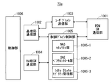
- FIG. 10 is a block diagram showing the configuration of the MME according to the present invention.
- FIG. 10 shows a configuration of the MME 73a included in the MME unit 73 shown in FIG.
- the PDN GW communication unit 1001 transmits and receives data between the MME 73a and the PDN GW.
- the base station communication unit 1002 performs data transmission / reception between the MME 73a and the base station 72 using the S1 interface. If the data received from the PDN GW is user data, the user data is passed from the PDN GW communication unit 1001 to the base station communication unit 1002 via the user plane communication unit 1003 to one or a plurality of base stations 72. Sent. When the data received from the base station 72 is user data, the user data is passed from the base station communication unit 1002 to the PDN GW communication unit 1001 via the user plane communication unit 1003 and transmitted to the PDN GW.
- control data is passed from the PDN GW communication unit 1001 to the control plane control unit 1005.
- control data is transferred from the base station communication unit 1002 to the control plane control unit 1005.
- the HeNBGW communication unit 1004 is provided when the HeNBGW 74 exists, and performs data transmission / reception through an interface (IF) between the MME 73a and the HeNBGW 74 according to the information type.
- the control data received from the HeNBGW communication unit 1004 is passed from the HeNBGW communication unit 1004 to the control plane control unit 1005.
- the result of processing in the control plane control unit 1005 is transmitted to the PDN GW via the PDN GW communication unit 1001. Further, the result processed by the control plane control unit 1005 is transmitted to one or a plurality of base stations 72 via the S1 interface via the base station communication unit 1002, and to one or a plurality of HeNBGWs 74 via the HeNBGW communication unit 1004. Sent.
- the control plane control unit 1005 includes a NAS security unit 1005-1, an SAE bearer control unit 1005-2, an idle state mobility management unit 1005-3, and the like, and performs overall processing for the control plane.
- the NAS security unit 1005-1 performs security of a NAS (Non-Access Stratum) message.
- the SAE bearer control unit 1005-2 manages a bearer of SAE (System Architecture) Evolution.
- the idle state mobility management unit 1005-3 performs mobility management in a standby state (idle state; also referred to as LTE-IDLE state or simply idle), generation and control of a paging signal in the standby state,
- the tracking area (TA) of one or a plurality of mobile terminals 71 is added, deleted, updated, searched, and tracking area list (TA List) management is performed.
- the MME 73a starts a paging protocol by transmitting a paging message to a cell belonging to a tracking area (tracking area: Tracking Area: TA) in which the UE is registered.
- the idle state mobility management unit 1005-3 may perform CSG management, CSG-ID management, and whitelist management of the Home-eNB 72-2 connected to the MME 73a.
- the relationship between the mobile terminal corresponding to the CSG-ID and the CSG cell is managed (for example, added, deleted, updated, searched).
- This relationship may be, for example, a relationship between one or a plurality of mobile terminals registered for user access with a certain CSG-ID and a CSG cell belonging to the CSG-ID.
- the white list management the relationship between the mobile terminal and the CSG-ID is managed (for example, added, deleted, updated, searched).
- one or a plurality of CSG-IDs registered by a certain mobile terminal as a user may be stored in the white list. Management related to these CSGs may be performed in other parts of the MME 73a.
- a series of processing of the MME 73a is controlled by the control unit 1006. Therefore, although not shown in FIG. 10, the control unit 1006 is connected to the units 1001 to 1005.
- MME 73a performs access control of one or a plurality of mobile terminals of CSG (ClosedGSubscriber Group) members.
- CSG Click-GSubscriber Group
- the MME 73a accepts execution of paging optimization (Paging optimization) as an option.
- FIG. 11 is a block diagram showing a configuration of the HeNBGW 74 shown in FIG. 7 which is the HeNBGW according to the present invention.
- the EPC communication unit 1101 performs data transmission / reception between the HeNBGW 74 and the MME 73a using the S1 interface.
- the base station communication unit 1102 performs data transmission / reception between the HeNBGW 74 and the Home-eNB 72-2 via the S1 interface.
- the location processing unit 1103 performs processing for transmitting registration information and the like among data from the MME 73a passed via the EPC communication unit 1101 to a plurality of Home-eNBs 72-2.
- the data processed by the location processing unit 1103 is passed to the base station communication unit 1102 and transmitted to one or more Home-eNBs 72-2 via the S1 interface.
- Data that does not require processing in the location processing unit 1103 and is simply passed (transmitted) is passed from the EPC communication unit 1101 to the base station communication unit 1102 and is sent to one or a plurality of Home-eNBs 72-2 via the S1 interface. Sent. A series of processing of the HeNBGW 74 is controlled by the control unit 1104. Therefore, although not shown in FIG. 11, the control unit 1104 is connected to the units 1101 to 1103.
- HeNBGW 74 The functions of HeNBGW 74 discussed in 3GPP are shown below (see Non-Patent Document 1, Chapter 4.6.2).
- the HeNBGW 74 relays for the S1 application. Although part of the procedure of the MME 73a to the Home-eNB 72-2, the HeNBGW 74 terminates for the S1 application not related to the mobile terminal 71.
- the HeNBGW 74 When the HeNBGW 74 is deployed, procedures unrelated to the mobile terminal 71 are communicated between the Home-eNB 72-2 and the HeNBGW 74, and between the HeNBGW 74 and the MME 73a.
- the X2 interface is not set between the HeNBGW 74 and other nodes.
- the HeNBGW 74 recognizes execution of paging optimization (Paging optimization) as an option.
- Paging optimization paging optimization
- FIG. 12 is a flowchart showing an outline from a cell search to a standby operation performed by a mobile terminal (UE) in an LTE communication system.
- the mobile terminal uses the first synchronization signal (P-SS) and the second synchronization signal (S-SS) transmitted from the neighboring base stations in step ST1201, and the slot timing, frame Synchronize timing.
- P-SS first synchronization signal
- S-SS second synchronization signal
- PP-SS and S-SS are collectively called synchronization signal (SS).
- SS synchronization signal
- a synchronization code corresponding to one-to-one is assigned to PCI (Physical Cell Identity) assigned to each cell.
- PCI Physical Cell Identity
- 504 patterns are under consideration. Synchronization is performed using the 504 PCIs, and the PCI of the synchronized cell is detected (specified).
- a cell-specific reference signal that is a reference signal (reference signal: RS) transmitted from the base station to each cell is detected.
- RS Reference Signal Received Power
- RSRP Reference Signal Received Power
- RS Reference Signal Received Power
- RS a code corresponding to PCI one to one is used. By correlating with that code, it can be separated from other cells. It is possible to detect the RS and measure the received power of the RS by deriving the RS code of the cell from the PCI specified in step ST1201.
- a cell having the best RS reception quality for example, a cell having the highest RS reception power, that is, the best cell is selected from one or more cells detected up to step ST1202.
- step ST1204 the PBCH of the best cell is received, and the BCCH that is broadcast information is obtained.
- MIB Master Information Block
- the MIB information includes, for example, DL (downlink) system bandwidth (also called transmission bandwidth setting (transmission bandwidth configuration: dl-bandwidth)), the number of transmission antennas, SFN (System frame number), and the like.
- SIB1 System Information Block 1 in the broadcast information BCCH.
- SIB1 includes information related to access to the cell, information related to cell selection, and scheduling information of other SIBs (SIBk; an integer of k ⁇ 2). Also, SIB1 includes TAC (Tracking Area Code).
- step ST1206 the mobile terminal receives the TAC of SIB1 received in step ST1205, and the TAC portion of the tracking area identifier (Tracking Area Identity: TAI) in the TA (Tracking Area) list already held by the mobile terminal.
- TAI Track Area Identity
- TAI is an identifier of TA, and is composed of MCC (Mobile Country Code), MNC (Mobile Network Code), and TAC (Tracking Area Code).
- MCC Mobile Country Code
- MNC Mobile Network Code
- TAC Track Area Code
- MCC Mobile Country Code
- MNC Mobile Network Code
- TAC Track Area Code
- step ST1206 If it is determined in step ST1206 that the TAC received in step ST1205 is the same as the TAC included in the TA (Tracking Area) list, the mobile terminal enters a standby operation in the cell. In comparison, if the TAC received in Step ST1205 is not included in the TA (Tracking Area) list, the mobile terminal passes through the cell to the core network (Core Network, EPC) including the MME and so on. Requests change of TA (Tracking Area) to perform Area Update. The core network updates the TA (Tracking Area) list based on the identification number (UE-ID or the like) of the mobile terminal sent from the mobile terminal together with the TAU request signal. The core network transmits an updated TA (Tracking Area) list to the mobile terminal. The mobile terminal rewrites (updates) the TAC list held by the mobile terminal based on the received TA (Tracking Area) list. Thereafter, the mobile terminal enters a standby operation in the cell.
- the core network Core Network, EPC
- CSG Cell Subscriber Group
- access is permitted only to one or a plurality of mobile terminals registered in the CSG cell.
- a CSG cell and one or a plurality of registered mobile terminals constitute one CSG.
- a CSG configured in this way is given a unique identification number called CSG-ID.
- One CSG may have a plurality of CSG cells. If a mobile terminal registers in any one CSG cell, it can access another CSG cell to which the CSG cell belongs.
- Home-eNB in LTE and LTE-A and Home-NB in UMTS may be used as a CSG cell.
- the mobile terminal registered in the CSG cell has a white list.
- the white list is stored in a SIM (Subscriber Identity Module) or USIM.
- the white list stores CSG information of CSG cells registered by the mobile terminal.
- CSG-ID, TAI (Tracking Area Identity), TAC, etc. can be considered as the CSG information.
- Either of the CSG-ID and the TAC may be used as long as they are associated with each other.
- ECGI may be used as long as CSG-ID and TAC are associated with ECGI.
- a mobile terminal that does not have a white list cannot access a CSG cell, and only accesses a non-CSG cell. Can not.
- a mobile terminal having a white list can access both a CSG cell of a registered CSG-ID and a non-CSG cell.
- the HeNB and HNB are required to support various services. For example, in a certain service, an operator registers a mobile terminal in a predetermined HeNB and HNB, and allows only the registered mobile terminal to access the HeNB and HNB cells, thereby allowing the mobile terminal to use the radio Increase resources to enable high-speed communication. Accordingly, the operator sets the charging fee higher than usual.
- CSG Cell that can be accessed only by registered (subscribed, member) mobile terminals.
- Many CSG (Closed Subscriber Group) cells are required to be installed in shopping streets, condominiums, schools, and companies. For example, a CSG cell is installed for each store in a shopping street, each room in a condominium, each classroom in a school, and each section in a company, and only a user registered in each CSG cell can use the CSG cell. Is required.
- HeNB / HNB is required not only to complement communication outside the coverage of the macro cell (area supplement type HeNB / HNB) but also to support various services as described above (service provision type HeNB / HNB). Yes. For this reason, a case where the HeNB / HNB is installed in the coverage of the macro cell may occur.
- RN relay node
- FIG. 13 is a diagram showing an architecture of a mobile communication system in the case of accompanying RN in Release 10 of 3GPP.
- the architecture of the mobile communication system shown in FIG. 13 (hereinafter may be simply referred to as “communication system”) is described in 3GPP TS 23.401 V10.3.0 (hereinafter referred to as “reference document 1”).
- the mobile communication system includes an RN MME 1301, a UE MME 1302, a UE 1303, an RN 1304, a DeNB 1305, a UE P-GW 1306, and a UE S-GW 1307.
- RN MME 1301 is an MME that manages RN 1304.
- the UE MME 1302 is an MME that manages the UE 1303.
- the RN MME 1301 and the UE MME 1302 may be configured in the same MME 1300.
- FIG. 13 illustrates a case where the RN MME 1301 and the UE MME 1302 are configured in the same MME 1300.
- the MME for RN 1301 and the MME for UE 1302 do not have to be configured in the same MME 1300.
- the UE P-GW 1306 is a P-GW for the UE 1303.
- the UE S-GW 1307 is an S-GW for the UE 1303.
- UE 1303 and RN 1304 are connected by Uu interface 1314.
- the RN 1304 and the DeNB 1305 are connected by an interface 1315 including an S1 interface, an X2 interface, and an Un interface.
- the DeNB 1305 and the RN MME 1301 are connected by an S1 interface 1308 and an S11 interface 1309.
- the MME 1302 for UE and the DeNB 1305 are connected by the S1 interface 1310.
- the MME 1302 for UE and the S-GW 1307 for UE are connected by the S11 interface 1311.
- the DeNB 1305 and the S-GW 1307 for UE are connected by the S1 interface 1316.
- the UE P-GW 1306 and the UE S-GW 1307 are connected by an S5 / S8 interface 1313.
- the UE P-GW 1306 and the external packet network are connected by an SGi interface 1312.
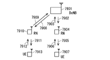
- RN is recognized as an eNB when viewed from a UE, and is recognized as a UE when viewed from a DeNB as a concept of an architecture of a mobile communication system with an RN.
- the RN operates as an eNB for the UE and operates as a UE for the DeNB.
- the DeNB is a function in which an eNB is added with a function for supporting the RN.
- the DeNB has the following two functions (1) and (2) in addition to the conventional functions of the eNB (see Non-Patent Document 1).
- S1 / X2 proxy functionality to support one or more RNs.
- S11 termination and S-GW / P-GW functionality to support one or more RNs.
- the RN When the RN operates as a UE, communication is performed between the RN, the DeNB, the MME for RN, and the S-GW / P-GW function of the DeNB.
- a Un interface is used for communication between the RN and the DeNB.
- the S1 interface is used for communication between the DeNB and the RN MME.
- the S11 interface is used for communication between the MME for RN and the S-GW / P-GW function of the DeNB.
- the RN when the RN operates as the eNB of the UE, communication is performed between the UE, the RN, the S1 / X2 proxy function of the DeNB, the MME for UE, and the S-GW for UE / P-GW for UE.
- a Uu interface is used for communication between the UE and the RN.
- the S1 interface is used via the S1 proxy function of the DeNB.
- the S11 interface is used for communication between the MME for UE and the S-GW for UE / P-GW for UE.
- the X2 interface is used instead of the S1 interface, the Uu interface is used for communication between the UE and the RN.
- the X2 interface is used via the X2 proxy function of the DeNB.
- mobile RN mobile relay, mobile RN
- Mobile RNs are disclosed in 3GPP R1-082975 (hereinafter referred to as “reference 2”) and 3GPP R3-1110656 (hereinafter referred to as “reference 3”).
- the moving RN is installed in a moving body such as a high-speed bus and a high-speed railway, and moves together with the moving body.
- the mobile RN relays communication between a passenger's mobile terminal (UE) in a mobile body such as a high-speed bus and a high-speed rail and a base station.
- UE passenger's mobile terminal
- FIG. 14 is a diagram for explaining a use case (use case) of the mobile RN.
- the base station 1402 exists in the coverage 1401 that the base station 1402 configures.
- FIG. 14 shows a case where one base station 1402 constitutes one cell.
- the cell corresponds to the base station 1402.
- the present invention is not limited to this, and one base station may constitute a plurality of cells.
- each cell corresponds to the base station 1402.
- the base station is an eNB, for example.
- the moving body for example, the high-speed bus 1406 exists in the coverage 1401 formed by the base station 1402 at the present time and moves along the direction of the arrow 1400.
- An RN 1407 is mounted on the high-speed bus 1406.
- Passengers on the express bus 1406 have UEs 1403 to 1405. In other words, UEs 1403 to 1405 are mounted on the high-speed bus 1406.
- the base station 1402 communicates with the RN 1407 that moves together with the high-speed bus 1406.
- the UEs 1403 to 1405 in the high-speed bus 1406 do not communicate directly with the base station 1402, but communicate with the base station 1402 via the RN 1407 mounted on the high-speed bus 1406. That is, the RN 1407 becomes a base station when viewed from the UEs 1403 to 1405 in the high-speed bus 1406.
- Mobile RN is considered to be effective as a means for solving these problems. Since the UE communicates with the mobile RN, there is no impact of Doppler shift on the UE and transmission loss between the inside and outside of the vehicle. Further, since the distance between the UE and the mobile RN is sufficiently shorter than the distance between the UE and the macro cell, the power consumption of the UE can be reduced. Furthermore, since the UE is connected to the mobile RN via an air interface, it is not necessary to perform HO, and signaling congestion (congestion) is solved. As a result, it is not necessary to newly install a macro cell, and the investment cost and operation cost of the operator can be reduced.
- FIG. 15 is a diagram illustrating an example of a sequence of RN setup processing.
- Step ST1501 the RN performs an attach process as an ordinary UE to the E-UTRAN or EPC for initial setting.
- the RN performs an attach process between the eNB, the MME for UE, and a home subscriber server (Home: Server: HSS).
- Home: Server: HSS home subscriber server
- Step ST1502 the RN reads out initial configuration parameters (initial configuration parameters) including a list of DeNB cells from the OAM for RN (Operation-Administration-and-Maintenance).
- Step ST1503 the RN performs a detach process as a normal UE from the network. Then, the RN activates Phase 2 of the RN setup method described later.
- step ST1501 The processing from step ST1501 to step ST1503 is referred to as phase 1 of the RN setup method.
- Step ST1504 the RN selects a DeNB from the list of DeNB cells obtained in Phase 1.
- Step ST1505 the RN performs an attach process as the RN.
- the RN transmits an RN indication (RN indication) to the DeNB.
- the DeNB includes the RN indication and the IP address (IP address) of the DeNB's S-GW / P-GW function in the initial UE message (Initial UE Message), and transmits it to the MME for RN.
- the MME for RN selects S-GW / P-GW for RN based on the initial UE message transmitted from the DeNB.
- the EPC checks whether or not the RN is permitted to perform the relay operation.
- step ST1504 The processing from step ST1504 to step ST1505 is referred to as phase 2 of the RN setup method.
- the problem to be solved in the first embodiment will be described below.
- the RN is a mobile RN
- the RN may move out of the coverage of the DeNB selected from the list of DeNB cells in step ST1504 at the time of setup illustrated in FIG.
- 3GPP there is no specific discussion about the communication method when the RN moves (see Reference 2 and Reference 3).
- the mobile RN executes a handover.
- a UE handover method (hereinafter also referred to as “handover method”) may be used. Thereby, it is possible to avoid complication of the mobile communication system.
- the link from the DeNB to the RN and the link from the RN to the UE are time-division multiplexed in one frequency band.
- the link from the DeNB to the DeNB and the link from the UE to the RN are also time division multiplexed in one frequency band.
- FIG. 29 and FIG. 30 to be described later show specific examples of subband configurations of the in-band RN.
- An in-band RN is an RN in which the frequency of the backhaul link and the frequency of the access link are the same.
- FIG. 29 and FIG. 30 show a case in which a downlink access link transmission does not interfere with downlink backhaul link reception or an uplink backhaul link transmission does not interfere with uplink access link reception in a certain RN. It shows that the frame is constructed. Therefore, there is no interference between the backhaul link and the access link in one RN.
- the subframe configuration of the RN backhaul link is individually notified from the DeNB for each RN using RRC signaling. Therefore, the subframe configuration of the backhaul link for the RN in the target eNB may be different from the subframe configuration of the backhaul link for the RN in the source DeNB. That is, when the RN starts communication based on the subframe configuration of the backhaul link for the RN in the source DeNB under the control of the target eNB, there is a possibility that interference in the relay may occur.
- the target eNB is the handover destination eNB.
- the source DeNB is a source eNB that is a handover source eNB and has a function of an RN.
- the following three (1) to (3) are disclosed as specific examples of the method for preventing the interference in the relay when the RN starts communication under the control of the target eNB.
- the mobile RN does not allocate resources to UEs being served thereby for a predetermined period.
- the mobile RN may notify a UE being served thereby of a hold command indicating that resource allocation is not performed for a predetermined period.
- the mobile RN may provide a gap that does not perform resource allocation for a predetermined period to UEs being served thereby.
- a specific example of the predetermined period is during the process of connecting to the target eNB, for example, during the process of steps ST1610 to ST1612 shown in FIG.
- a specific example of the end of the predetermined period is until a notification of the subframe configuration of the backhaul link is received from the target eNB.
- the source DeNB notifies the target eNB of the backhaul link subframe configuration set for the mobile RN.
- a specific example of the notification method of the subhaul configuration of the backhaul link is disclosed below.
- the source DeNB notifies the target eNB of the subframe configuration of the backhaul link that has been set in the mobile RN, together with notifying the handover request (Handover Request).
- the target eNB that has received the subframe configuration of the backhaul link configured by the source DeNB performs scheduling for the RN in order to execute connection processing with the RN based on the subframe configuration. Thereafter, the target eNB may notify the RN of the subframe configuration of the backhaul link again.
- the target eNB notifies the source DeNB of the subframe configuration of the backhaul link that is set after the handover of the RN.
- the target eNB may notify the source DeNB of the parameters necessary for calculating the CRC of the own cell and the resource.
- the source DeNB notifies the RN of the subframe configuration of the backhaul link set to the RN by the target eNB using the mobility control information or the handover command.
- the RN performs connection processing with the target eNB based on the subframe configuration of the backhaul link set in the RN by the target eNB.
- the scheduling of the access link to the UE being served after the handover and the MBSFN subframe configuration may be determined.
- the mobile RN handover is supported using the UE handover method as it is, the following new problem occurs in the selection of the target eNB.
- FIG. 16 is a diagram illustrating an example of a handover process sequence based on the X2 interface.
- step ST1601 the source eNB that is the handover source eNB notifies the UE of measurement control (Measurement Control).
- the measurement control is also referred to as measurement configuration.
- the source eNB corresponds to a source base station apparatus.
- step ST1602 the UE performs measurement according to the measurement control received in step ST1601.
- step ST1603 according to the measurement control received in step ST1601, the UE notifies the source eNB of a measurement report (Measurement Report) for reporting the measurement result in step ST1602.
- Measurement Report a measurement report for reporting the measurement result in step ST1602.
- the source eNB determines whether to execute handover, that is, whether to perform handover of the UE, based on the measurement report received in step ST1603.
- the source eNB determines a target eNB that is a handover destination eNB.
- the target eNB corresponds to a destination base station apparatus.
- step ST1605 the source eNB notifies the target eNB of a handover request (Handover Request).
- Step ST1606 the target eNB determines whether or not the handover can be accepted based on the resource (Admission Control).
- the mobile station moves to step ST1607.
- the target eNB determines that the handover cannot be accepted, it is treated as ending the process, and the description is omitted.
- step ST1607 the target eNB notifies the source eNB of acceptance of handover request (Handover Request Ack).
- Step ST1608 the source eNB notifies the UE of an RRC connection reconfiguration message (RRC Connection Reconfiguration Message) including mobility control information (Mobility Control Information) in which parameters necessary for handover are mapped.
- RRC Connection Reconfiguration Message RRC Connection Reconfiguration Message
- mobility control information Mobility Control Information
- step ST1609 the source eNB delivers data on the UE to the target eNB (Data Forwarding).
- Step ST1610 the UE tries to connect to the target eNB using the parameter received in Step ST1608. Specifically, the UE transmits an RACH to the target eNB and transmits an RRC connection request (RRC connection request (RRC Connection Request)).
- RRC connection request RRC Connection Request
- step ST1611 the target eNB notifies the UE of timing advance (Timing Advance: TA) as a response to the RRC connection request transmitted from the UE in step TS1610.
- TA Timing Advance
- Step ST1612 the UE notifies the target eNB of RRC connection reconfiguration completion (RRC Connection Reconfiguration Complete).
- FIG. 17 is a diagram showing an example of a handover process sequence based on the S1 interface. Since the sequence shown in FIG. 17 is similar to the sequence shown in FIG. 16, the same steps are denoted by the same step numbers, and common description is omitted.
- Step ST1700 the source eNB determines whether there is no X2 interface between the source eNB and the target eNB. If the source eNB determines that the X2 interface does not exist, the source eNB moves to step ST1701, and if the source eNB determines that the X2 interface exists, the handover process based on the S1 interface ends.
- step ST1701 the source eNB determines to execute handover based on the S1 interface, that is, to perform handover on an S1 basis. For example, when there is no X2 interface between the source eNB and the target eNB, the source eNB moves from step ST1700 to step ST1701, and performs handover based on the S1 interface (hereinafter referred to as “S1-based handover”). Execute).
- the source eNB notifies the source MME, which is an MME that manages the source eNB, of a handover request (Handover Required) including the identifier of the target eNB.
- the source MME notifies the target MME, which is the MME that manages the target eNB, of a forward relocation request (Forward Relocation) Request) including the identifier of the target eNB.
- a forward relocation request Forward Relocation
- Step ST1704 the target MME notifies the target eNB of a handover request (Handover request) including an EPS bearer setup request.
- Step ST1705 the target eNB determines whether or not the handover can be accepted based on whether or not the requested EPS bearer setup has been accepted. If the target eNB can accept the setup of the EPS bearer, the target eNB judges that the handover can be accepted, and judges that the handover cannot be accepted if the setup of the EPS bearer cannot be accepted.
- the target eNB When the target eNB determines that the handover can be accepted, the target eNB notifies the target MME of the handover request acceptance (Handover Request Ack). The description when the target eNB determines that the handover cannot be accepted is omitted.
- step ST1706 the target MME notifies the source MME of a forward relocation response (Forward Relocation Response).
- step ST1707 the source MME notifies the source eNB of a handover command (Handover Command).
- Step ST1708 the source eNB notifies the UE of a handover command (Handover Command) in which parameters necessary for the handover are mapped.
- a handover command Handover Command
- Step ST1709 the UE connects to the target eNB and notifies handover approval (Handover Confirm).
- the source eNB determines the target eNB.
- the DeNB is obtained by adding a function for supporting the RN to the conventional function of the eNB. That is, not all eNBs have the DeNB function. Therefore, the source eNB may select an eNB that cannot support the RN, that is, an eNB that does not have the DeNB function, as the target eNB.
- the RN is connected to the radio access network via the DeNB. In other words, the RN cannot connect to the radio access network without going through the DeNB.
- the source eNB selects an eNB that cannot support the RN, that is, an eNB that does not have the DeNB function, as a target eNB, the RN is not supported as an RN by the target eNB of the movement destination. As a result, there arises a problem that service to UEs being served by the RN is stopped.
- the target eNB indicates rejection to the RN.
- the RN rejected from the target eNB may stop the handover process and return to the source eNB.
- the rejected RN may perform a search for neighboring cells and select another eNB as the DeNB.
- the source eNB of the RN may be referred to as “source DeNB”.
- the following two (1) and (2) are disclosed as specific examples of a method for determining whether to deny access to the target eNB of the RN.
- the target eNB judges whether or not to reject the RN access. When the target eNB itself does not have the DeNB function for the access from the RN, it is determined to reject the access.
- (1-1) Use RN indication sent from RN during RRC connection establishment.
- the RN indication that the RN notifies the target eNB in the attach process as the RN may be used.
- the target eNB determines that the access is from the RN when the RN indication exists, and determines that the access is not from the RN when the RN indication does not exist.
- connection request from RN is newly provided as “connection request from RN”.
- a connection request from RN may be “connection request from RN” or “attach from RN”. For example, if the target eNB receives the RRC connection request and the establishment reason is “attach from RN”, the target eNB determines that the access is from RN, and if the establishment reason is not “attach from RN”, It is determined that the access is not from the RN.
- the EPC determines whether or not to reject the RN access.
- a specific example of EPC is MME.
- the MME instructs the target eNB to reject the access.
- the MME When the eNB does not have the DeNB function, the IP address of the S-GW / P-GW function cannot be included in the initial UE message (Initial UE UE Message) for the MME. Therefore, the MME notifies the initial UE message when the IP address of the S-GW / P-GW function is not included in the initial UE message from the target eNB despite the access from the RN. The determined eNB does not have the DeNB function. When the initial UE message from the target eNB includes the IP address of the S-GW / P-GW function, the MME determines that the eNB that has notified the initial UE message has the DeNB function.
- a specific example of a method for determining that the MME is an access from the RN is disclosed below.
- the MME determines that the access is from the RN, and when the RN indication is not included, the MME must be an access from the RN. to decide.
- the MME instructs the target eNB to reject the access.
- the MME instructs the target eNB using the S1 interface or using S1 signaling.
- the reason may be added to the rejection notification to the RN.
- the reason is that the rejection is based on the reason that the target eNB does not have the DeNB function or the rejection is based on the reason that the RN is not permitted to perform the relay operation.
- the EPC checks whether or not the RN is permitted to perform the relay operation.
- the RN can recognize the reason for refusing access.
- the reason for refusal is “the reason that the target eNB does not have the DeNB function” or “the reason that the RN is not permitted to perform the relay operation”.
- the RN knows the reason for the access rejection, the following effects can be obtained.
- the rejection is based on the reason that the target eNB does not have the DeNB function, the RN can recognize that it may be supported as the RN by reselecting another cell.
- the target eNB notifies the RN of RRC connection rejection (RRC Connection Reject).
- the reason may be added to the rejection notification to the RN. Specifically, a reason is added that the rejection is based on the reason that the target eNB does not have the DeNB function. By adding the reason for refusal to the rejection notice in this way, the RN can recognize the reason for refusing access. When the RN knows the reason for the access rejection, the following effects can be obtained. If the target eNB is a rejection based on the reason that it does not have the DeNB function, the RN can recognize that it may be supported as an RN by reselecting another cell.
- the operation When handover of a mobile RN is supported by a conventional UE handover method, the UE operation illustrated in FIG. 16 and FIG. 17 is replaced with an RN operation.
- the RN accesses the target eNB in step ST1610 of FIG.
- the RN accesses the target eNB in Step ST1709 of FIG.
- FIG. 18 and FIG. 18 and 19 show part of the overall handover sequence. Specifically, FIG. 18 and FIG. 19 show in detail the parts of step ST1610 in FIG. 16 and step ST1709 in FIG. 17 when the mobile RN handover is supported by the conventional UE handover method. .
- FIG. 18 is a diagram showing an exemplary sequence of the mobile communication system in the first embodiment.
- FIG. 18 shows a sequence in a case where the target eNB determines whether or not to reject access of the RN.
- Step ST1801 the RN notifies the target eNB of an RRC connection request (RRC Connection Request). At this time, the establishment reason is “attach from RN”.
- Step ST1802 the target eNB determines whether or not the establishment reason in the RRC connection request received in Step ST1801 indicates “attach from RN”. When it is determined that the establishment reason indicates “attach from RN”, the mobile terminal makes a transition to step ST1803. If it is determined that the establishment reason does not indicate “attach from RN”, the process proceeds to step ST1805. In this step ST1802, the target eNB judges whether or not the access is from the RN.
- step ST1803 the target eNB determines whether or not the own device has the DeNB function. When it is judged that it does not have a DeNB function, it transfers to step ST1804. When it is judged that it has a DeNB function, it transfers to step ST1805.
- Step ST1804 the target eNB notifies the RN of RRC connection rejection (RRC Connection Reject).
- the target eNB that does not have the DeNB function indicates rejection to the RN.
- step ST1805 the target eNB notifies the RN of the RRC connection setup (RRC Connection Setup).
- Step ST1806 the RN confirms the response of the RRC connection request notified to the target eNB in Step ST1801.
- the RN determines whether an RRC connection rejection has been received. If it is determined that RRC connection rejection has been received, that is, if RRC connection setup has not been received, the mobile terminal makes a transition to step ST1807. If it is determined that RRC connection rejection has not been received, that is, if RRC connection setup has been received, the mobile terminal makes a transition to step ST1808.
- Step ST1807 the RN stops the handover process and returns to the source eNB.
- Step ST1808 the RN continues the handover process and continues the connection process with the target eNB. That is, the process returns to step ST1610 in FIG. 16 or step ST1709 in FIG.
- FIG. 19 is a diagram showing an exemplary sequence of the mobile communication system in the first embodiment.
- FIG. 19 shows a sequence in the case where the EPC determines whether or not to reject the access of the RN.
- Step ST1901 the RN notifies the target eNB of the RN indication during RRC connection establishment.
- step ST1803 the target eNB judges whether or not the own device has a DeNB function. When it judges that it does not have a function of DeNB, it transfers to step ST1902. When it is judged that it has a DeNB function, it transfers to step ST1903.
- Step ST1902 the target eNB notifies the MME of an initial UE message that maps the RN indication and does not map the IP address of the S-GW / P-GW function.
- the target eNB that does not have the DeNB function cannot map the IP address of the S-GW / P-GW function to the initial UE message.
- step ST1903 the target eNB maps the RN indication and notifies the MME of the initial UE message in which the IP address of the S-GW / P-GW function is mapped.
- Step ST1904 the MME determines whether or not the RN indication is included in the initial UE message received from the target eNB that is a subordinate eNB. When it is determined that the RN indication is included in the initial UE message, it is determined that the access is from the RN, and the mobile terminal makes a transition to step ST1905. If it is determined that the RN indication is not included in the initial UE message, it is determined that the access is not from the RN and is not a characteristic part of the present invention. .
- Step ST1905 the MME determines whether or not the IP address of the S-GW / P-GW function is included in the initial UE message received from the target eNB that is a subordinate eNB. When it is determined that the IP address is not included in the initial UE message, it is determined that the target eNB does not have the DeNB function, and the process moves to Step ST1906. If it is determined that the IP address is included in the initial UE message, it is determined that the target eNB has the DeNB function and is not a characteristic part of the present invention. finish.
- Step ST1906 the MME instructs the target eNB to reject access from the RN.
- Step ST1907 the target eNB instructed to reject access from the RN in Step ST1906 notifies the RN of access rejection.
- the target eNB notifies the RN of RRC connection rejection (RRC Connection Reject).
- step ST1806 the RN determines whether or not an RRC connection rejection has been received. If the RN determines that an RRC connection rejection has been received, the RN moves to step ST1807 and determines that no RRC connection rejection has been received. Moves to step ST1808.
- Step ST1807 the RN stops the handover process and returns to the source eNB.
- Step ST1808 the RN continues the handover process and continues the connection process with the target eNB. That is, the process returns to step ST1610 in FIG. 16 or step ST1709 in FIG.
- the target eNB can reject the RN.
- the RN can return to the connection with the source eNB or select another eNB as the DeNB, and thus can continue the connection with the base station apparatus. Therefore, even when the RN moves, communication can be continued between the RN and the base station apparatus, so that a communication service to UEs being served by the RN can be continued.
- Specific examples (1) and (2) of the method for determining whether to deny access to the target eNB of the RN disclosed in the present embodiment can be used in the embodiments described later. Or it can use not only at the time of a hand-over but at the time of access from RN.
- Embodiment 1 Modification 1 In the first modification of the first embodiment, another solution is disclosed for the same problem as in the first embodiment. A solution in the first modification of the first embodiment will be described below.
- the target eNB stops the handover started by the source DeNB.
- the source DeNB stops the handover process.
- the source DeNB may notify the target eNB that the handover target entity is an RN.
- the source DeNB may cancel the handover process or reselect the target eNB.
- the following two (1) and (2) are disclosed as specific examples of the method in which the source DeNB determines whether or not the handover target entity is an RN.
- the RN transmits an RN indication (RN indication) to the DeNB.
- the RN may send a mobile RN indication.
- the DeNB stores the RN indication in association with the cell identifier, PCI, CGI, and the like.
- the source DeNB determines whether or not it is an RN based on the identifier of the handover target cell.
- the RN When the RN notifies the source DeNB of the measurement report, the RN also notifies that it is an RN. Alternatively, the RN may send a mobile RN indication. You may add the indicator of whether it is RN as an information element of a measurement report. Or you may add the indicator of whether it is a mobile RN as an information element of a measurement report.
- the source DeNB determines whether or not to hand over the RN based on the measurement report or the like. Compared with the above-described method (1), the source DeNB can collectively receive information related to handover, so that the processing load of the source DeNB can be reduced.
- the following two (1) and (2) are disclosed as specific examples of a method for notifying the target eNB that the entity to be handed over is an RN when the source DeNB starts a handover. .
- the source DeNB When a handover method based on the X2 interface is used, the source DeNB notifies that the handover target entity is an RN when a handover request is made to the target eNB. As an information element of the handover request, an indicator as to whether the entity to be handed over is an RN may be added.
- the source DeNB When the handover method based on the S1 interface is used, the source DeNB notifies the handover target entity together with the RN when making a handover request to the source MME.
- an indicator as to whether the entity to be handed over is an RN may be added.
- the source DeNB When the source DeNB and the target eNB are managed by the same MME, the source DeNB is notified to the target eNB via the MME that the entity to be handed over is an RN. When the source DeNB and the target eNB are managed by different MMEs, the source DeNB notifies the source MME and the target eNB via the target MME that the entity to be handed over is an RN.
- a handover request rejection (Handover Request Nack or Handover preparation ⁇ ⁇ ⁇ ⁇ Failure) is notified.
- the handover method based on the S1 interface when used, the following method may be used.
- the MME manages whether the subordinate eNB supports the DeNB function.
- the MME stores the identifier of the cell and whether or not it supports the DeNB function.
- the source DeNB When the source DeNB starts a handover, the source DeNB notifies that the entity to be handed over is an RN and the cell identifier of the target eNB.
- the MME that manages the target eNB may determine whether or not the target eNB has a DeNB function based on the cell identifier of the target eNB before notifying the target eNB of the handover request.
- the MME determines that the target eNB does not have the DeNB function
- the MME stops the handover.
- the MME determines that the target eNB has the DeNB function
- the MME notifies the target eNB of a handover request.
- FIG. 20 shows details of steps ST1603 to ST1607 in FIG. 16
- FIG. 21 shows details of steps ST1603 to ST1705 in FIG.
- FIG. 20 is a diagram showing an exemplary sequence of the mobile communication system in the first modification of the first embodiment.
- FIG. 20 shows a sequence when handover processing based on the X2 interface is used.
- step ST2001 the RN notifies the source DeNB that the measurement report (Measurement Report) and the handover target entity is the RN.
- Step ST1604 the source DeNB judges whether or not to hand over the UE based on the measurement report received in Step ST2001.
- a target eNB that is a handover destination is determined.
- step ST2002 the source DeNB notifies the target eNB that a handover request (Handover Request) and that the handover target entity is an RN.
- step ST2003 the target eNB determines whether the entity to be handed over is an RN. If the target eNB receives from the source DeNB that the handover target entity is an RN together with a handover request, the target eNB determines that the handover target entity is an RN and moves to step ST2004. If the target eNB has not received from the source DeNB that the handover target entity is an RN along with the handover request, the target eNB determines that the handover target entity is not an RN and moves to Step ST1606 in FIG.
- step ST2004 the target eNB determines whether or not the own device has the DeNB function. When it judges that it does not have a function of DeNB, it transfers to step ST2005. If it is determined that the DeNB function is provided, the process proceeds to step ST1606 in FIG.
- step ST2005 the target eNB notifies the source DeNB of handover request rejection (Handover Request Nack).
- step ST2006 the source DeNB that has received the handover request rejection in step ST2005 reselects the target eNB. Further, the source DeNB may request measurement from the RN. The source DeNB may notify the RN of measurement control. The measurement control may have a different content from the previous measurement control.
- FIG. 21 is a diagram showing an exemplary sequence of the mobile communication system in the first modification of the first embodiment.
- FIG. 21 shows a sequence in the case of using a handover process based on the S1 interface.
- Step ST2101 the target MME stores whether the subordinate eNB has the DeNB function, that is, whether the DeNB function is supported.
- step ST2001 the RN notifies the source DeNB that the measurement report (Measurement Report) and the handover target entity is the RN.
- Step ST1604 the source DeNB judges whether or not to hand over the UE based on the measurement report received in Step ST2001.
- a target eNB that is a handover destination is determined.
- the source DeNB determines to execute a handover based on the S1 interface. For example, when there is no X2 interface between the source DeNB and the target eNB, a handover based on the S1 interface is executed.
- Step ST2102 the source DeNB notifies the source MME that a handover request (Handover Required) and that the handover target entity is an RN.
- Step ST2103 the source MME notifies the target MME that manages the target eNB of a forward relocation request (Forward Relocation Request) including the identifier of the target eNB and the fact that the entity to be handed over is an RN.
- Forward Relocation Request a forward relocation request including the identifier of the target eNB and the fact that the entity to be handed over is an RN.
- Step ST2104 the target MME determines whether or not the target eNB has the DeNB function. When it is judged that it does not have a DeNB function, it transfers to step ST2105. When it is determined that the DeNB function is provided, the mobile terminal makes a transition to step ST1704 in FIG.
- step ST2105 the target MME notifies the source MME that the forward relocation request is rejected.
- step ST2106 the source MME notifies the source DeNB of handover request rejection (Handover preparation Failure).
- step ST2006 the source DeNB that has received the handover request rejection in step ST2106 reselects the target eNB. Further, the source DeNB may request measurement from the RN. The source DeNB may notify the RN of measurement control. The measurement control may have a different content from the previous measurement control.
- the source DeNB can recognize that the target eNB does not have the DeNB function at an earlier stage of the handover process than in the first embodiment. This eliminates the need for the RN to execute a connection to the target eNB. Also, the source DeNB can select another eNB as the target eNB. Therefore, it is possible to reduce the control delay as compared with the first embodiment.
- Embodiment 1 Modification 2 The problem to be solved by the second modification of the first embodiment will be described below.
- a handover that is always rejected is activated because the target eNB does not have the DeNB function. This causes a problem in terms of processing load as a mobile communication system and control delay.
- the source DeNB may select an eNB having the DeNB function as a target eNB using the determination result of whether or not the eNB of the RN has the DeNB function. . In other words, the source DeNB does not select an eNB that does not have a DeNB function as a target eNB.
- the following three (1) to (3) are disclosed as specific examples of a method for determining whether an eNB has a DeNB function in the RN.
- the RN receives the eNB broadcast information, and determines whether the eNB has the DeNB function based on the received broadcast information.
- SIB System Information Block
- SIB1 Add as SIB1 information element.
- SIB1 can be received at the initial stage of search.
- reception is possible in step ST1205 of FIG. Therefore, by mapping information indicating whether or not it has the DeNB function to SIB1, control delay can be prevented and power consumption can be reduced.
- SIB2 information element When mapped to SIB2, the following effects can be obtained.
- the radio resource setting common to all mobile terminals being served by SIB2 is mapped to SIB2.
- Information common to all RNs can be added to the SIB2 including similar parameters by receiving the same system information. Therefore, complication of the mobile communication system can be avoided, and control delay can be prevented.
- SIB3 is a direction in which common settings for cell reselection are mapped.
- Information common to cell reselection can be added to SIB3 including similar parameters by receiving the same system information. Therefore, complication of the mobile communication system can be avoided, and control delay can be prevented.
- information indicating whether or not the DeNB function is present may be reported only from the eNB having the DeNB function. When the information is not broadcast, there is no problem because it can be determined that the DeNB function is not provided. Further, additional information is not required for an eNB that does not have a DeNB function.
- the cell identifier assigned to the eNB having the DeNB function is separated from the cell identifier assigned to the eNB not having the DeNB function.
- the PCI can be recognized by the RN at an early stage of measurement performed by the RN. Specifically, using the first synchronization signal (P-SS) and the second synchronization signal (S-SS) transmitted from the surrounding base stations, a synchronization code corresponding to PCI one-to-one is used. Recognize (see step ST1201 in FIG. 12).
- the PCI range assigned to the eNB having the DeNB function may be separated from the PCI range assigned to the eNB not having the DeNB function.
- the eNB broadcasts the cell identifier separation method or the PCI range separation method.
- the RN determines whether or not the eNB has the DeNB function by using an eNB cell identifier or PCI.
- the cell identifier separation method or the PCI range separation method may be broadcast only from the eNB having the DeNB function. As a result, additional information is not required for an eNB that does not have a DeNB function.
- the carrier frequency for eNB having the DeNB function is separated from the carrier frequency for eNB not having the DeNB function.
- the eNB broadcasts the frequency separation method.
- the RN uses the carrier frequency of the eNB to determine whether the eNB has a DeNB function.
- the frequency separation method may be broadcast only from an eNB having a DeNB function. As a result, additional information is not required for an eNB that does not have a DeNB function.
- the following four (1) to (4) are disclosed as specific examples of the method of notifying the source eNB of the determination result of whether the eNB has the DeNB function in the RN.
- An eNB whose RN does not have a DeNB function is excluded from measurement.
- the RN does not measure an eNB that does not have a DeNB function. That is, the RN notifies the source DeNB of the eNB having the DeNB function as a target eNB candidate.
- the source DeNB judges that the target eNBs of all measurement reports notified from the RN have the DeNB function.
- An eNB whose RN does not have a DeNB function is excluded from measurement reports.
- the RN does not report the measurement of the eNB that does not have the DeNB function to the source DeNB. That is, the RN notifies the source DeNB of the eNB having the DeNB function as a target eNB candidate.
- the source DeNB judges that the target eNBs of all measurement reports notified from the RN have the DeNB function.
- the RN When the RN makes a measurement report, it also notifies whether or not the target eNB has the DeNB function.
- an indicator as to whether the target eNB has the DeNB function may be added.
- the source DeNB uses the indicator of whether or not it has the DeNB function to determine whether or not the measurement report target eNB has the DeNB function.
- the RN performs a measurement report targeting the eNB having the best reception quality among the eNBs having the DeNB function to the source DeNB. That is, the RN notifies the source DeNB of the eNB having the DeNB function as the target eNB. The source DeNB determines that the target eNB of the measurement report notified from the RN has the DeNB function.
- the DeNB selects which one of the methods to notify the source eNB of the determination result as to whether or not the eNB in the RN of (1) to (4) has the DeNB function to the RN. You may do it.
- the following three (1) to (3) are disclosed as specific examples of the method in which the DeNB notifies the RN of the selected method.
- Notification is made by S1 signaling using the S1 interface.
- measurement control Measurement Control
- it is also notified.
- an indicator indicating a method for notifying the source eNB of the determination result of whether or not the eNB at the selected RN has the DeNB function may be added.
- broadcast information a method for notifying the source eNB of the determination result as to whether or not the eNB in the RN has the DeNB function is notified.
- a specific example of a method by which the source DeNB determines whether an entity to be handed over is an RN is the same as that of the first modification of the first embodiment described above, and thus the description thereof is omitted.
- FIG. 22 shows part of the overall handover sequence. Specifically, FIG. 22 shows details of steps ST1601 to ST1604 in FIGS.
- FIG. 22 is a diagram showing an exemplary sequence of the mobile communication system in the second modification of the first embodiment.
- the source DeNB notifies the RN of measurement control (Measurement Control).
- the source DeNB instructs the RN to notify the source DeNB of the determination result as to whether or not the eNB at the RN has the DeNB function.
- This operation example will be described below assuming that a method for notifying whether or not the target eNB has the DeNB function is instructed at the time of the measurement report.
- step ST2202 the RN performs measurement according to the measurement control received in step ST2201.
- the broadcast information of the measurement target eNB is received, decoded, and information indicating whether or not the DeNB function mapped to the broadcast information is confirmed.
- Step ST2203 the RN notifies the source DeNB of the measurement report (Measurement Report) according to the measurement control received in Step ST2201. In addition, the RN notifies the source DeNB of the determination result of whether the measurement report target eNB has the DeNB function and the fact that the handover target entity is the RN.
- step ST2204 the source DeNB judges whether the entity to be handed over is an RN. If the source DeNB receives from the RN that the handover target entity is the RN along with the measurement report, the source DeNB determines that the handover target entity is the RN and moves to Step ST2205. If the source DeNB has not received from the RN that the handover target entity is an RN along with the measurement report, the source DeNB determines that the handover target entity is not an RN, and proceeds to step ST1604 in FIG. 16 and FIG. .
- step ST2205 the source DeNB determines whether to execute handover, specifically, whether to perform handover of the RN, based on the measurement report received in step ST2203. If the source DeNB determines that the RN is to be handed over, in step ST2206, the eNB having the DeNB function based on the determination result of whether or not the measurement report target eNB received in step ST2203 has the DeNB function To determine the target eNB. In other words, the source DeNB selects an eNB having the DeNB function as a target eNB.
- Step ST2206 when the target eNB is determined from the eNB having the DeNB function, the process proceeds to Step ST1605 in FIG. 16 or Step ST1701 in FIG.
- the following effects can be obtained by the second modification of the first embodiment. It is possible to prevent the handover that is always rejected from being activated because the target eNB does not have the DeNB function. Thereby, the processing load as a mobile communication system can be reduced, and a control delay can be prevented.
- Embodiment 1 Modification 3 In the third modification of the first embodiment, another solution is disclosed for the same problem as that of the second modification of the first embodiment. A solution in the third modification of the first embodiment will be described below.
- the source DeNB it is determined whether the neighboring eNB has the DeNB function. Further, when the handover target entity is an RN, the source DeNB may select an eNB having the DeNB function as the target eNB. In other words, the source DeNB does not select an eNB that does not have a DeNB function as a target eNB.
- the following three (1) to (3) are disclosed as specific examples of the method for determining whether or not the neighboring eNB has the DeNB function in the source DeNB.
- the source DeNB sets up as a base station, information on whether or not the neighboring cell has the DeNB function is acquired from the OAM as part of the neighboring cell information or separately from the neighboring cell information.
- Only the eNB having the DeNB function may acquire information on whether or not the neighboring cell has the DeNB function. An effect that an additional function is not required can be obtained for an eNB that does not have a DeNB function.
- (1-1) to (1-3) are disclosed as specific examples of information on whether or not the neighboring cell has the DeNB function.
- (1-1) Information on whether or not the eNB has a DeNB function in association with the cell identifier of the neighboring eNB.
- (1-2) PCI range information to be allocated to an eNB having the DeNB function.
- (1-3) Information on the carrier frequency used by the eNB having the DeNB function.
- information on whether or not the neighboring cell has the DeNB function may be changed due to the other reason that the eNB having the DeNB function is newly installed or the eNB having the DeNB function is removed. There is also sex.
- the following is disclosed as a specific example of a method that considers the possibility that information on whether or not a neighboring cell has the DeNB function is changed.
- the OAM When there is a change in information on whether or not the neighboring cell has the DeNB function, the OAM notifies the source DeNB.
- the source DeNB receives and decodes the broadcast information of the neighboring eNB, and broadcast information The information indicating whether or not it has the DeNB function mapped to is confirmed.
- the source DeNB stores whether or not the eNB has the DeNB function in association with the cell identifier of the neighboring eNB.
- the following is disclosed as a specific example of a method that considers the possibility that information on whether or not a neighboring cell has the DeNB function is changed.
- the source DeNB periodically receives broadcast information of neighboring eNBs, decodes it, and confirms information indicating whether or not it has a DeNB function mapped to the broadcast information.
- the DeNB queries the MME or the RN OAM for information on whether or not the neighboring cell has the DeNB function as part of the neighboring cell information or separately from the neighboring cell information. .
- the following three (3-1) to (3-3) are disclosed as specific examples of triggers for the DeNB to execute an inquiry.
- information on whether or not the neighboring cell has the DeNB function may be changed due to the other reason that the eNB having the DeNB function is newly installed or the eNB having the DeNB function is removed. There is also sex.
- the following is disclosed as a specific example of a method that considers the possibility that information on whether or not a neighboring cell has the DeNB function is changed.
- the source DeNB periodically acquires information on whether or not the neighboring cell has the DeNB function from the MME or OAM as part of the neighboring cell information or separately from the neighboring cell information.
- the specific example of the method by which the source DeNB determines whether the handover target entity is an RN is the same as that of the first modification of the first embodiment, and thus the description thereof is omitted.
- the following (1) and (2) are disclosed as specific examples of a method in which the source DeNB selects an eNB having a DeNB function as a target eNB.
- the source DeNB determines whether the target eNB of the measurement report has the DeNB function based on the identifier of the cell included in the measurement report.
- the source DeNB selects an eNB having the DeNB function as a target eNB.
- the source DeNB notifies the RN that the eNB having the DeNB function is to be measured.
- the source DeNB selects a target eNB from the target eNBs of measurement reports from the RN. Since the measurement target of the RN is an eNB having the DeNB function, the source DeNB may select the target eNB from the measurement report target eNB.
- the following two (2-1) and (2-2) are disclosed as specific examples of the notification method of the measurement target.
- the source DeNB maps information on whether or not the neighboring eNB has the DeNB function to the broadcast information.
- the broadcast information may be mapped as a neighbor cell list (neighbor cell list), neighbor cell information, or neighbor cell configuration (neighbor cell configuration).
- the RN receives and decodes the broadcast information, and uses an eNB having a DeNB function as a measurement target.
- the UE other than the RN that is, the UE can receive a service from an eNB that does not have a DeNB function, and thus does not need to recognize an eNB that does not have a DeNB function.
- the following two (2-1-1) and (2-1-2) are disclosed as specific examples of information indicating whether or not the DeNB function is provided.
- (2-1-1) Notifying the identifier of the cell of the neighboring eNB having the DeNB function. You may notify the PCI range allocated to eNB which has a DeNB function. You may notify the identifier of the cell of a periphery eNB, and the indicator of whether this eNB has a DeNB function in association.
- (2-1-2) Notify the carrier frequency of the eNB having the DeNB function.
- the source DeNB designates an eNB having a DeNB function as a measurement object for measurement control to the RN.
- the following two (2-2-1) and (2-2-2) are disclosed.
- (2-2-1) Designated by the identifier of the eNB cell having the DeNB function. You may specify in the range of the identifier of the cell of eNB which has a function of DeNB. You may specify in the range of PCI allocated to eNB which has a DeNB function.
- (2-2-2) Notify the carrier frequency of the eNB having the DeNB function.
- FIG. 23 is a diagram showing an exemplary sequence of the mobile communication system in the third modification of the first embodiment.
- FIG. 23 illustrates a sequence in a case where the method in which the source DeNB judges is used as a method in which the source DeNB selects an eNB having the DeNB function as a target eNB.
- step ST2301 the OAM notifies the source DeNB of information on whether or not the neighboring cell has the DeNB function.
- the source DeNB acquires information on whether or not the neighboring cell has the DeNB function from the OAM in step ST2301.
- Step ST1601 the source DeNB that is a handover source notifies the UE of measurement control (Measurement Control).
- step ST1602 the UE performs measurement according to the measurement control received in step ST1601.
- step ST2001 the RN notifies the source DeNB that the measurement report (Measurement Report) and the handover target entity is the RN.
- step ST2204 the source DeNB judges whether the entity to be handed over is an RN. If the source DeNB receives from the UE that the handover target entity is an RN together with the measurement report, the source DeNB determines that the handover target entity is an RN and moves to Step ST2302. If the source DeNB has not received from the RN that the handover target entity is an RN along with the measurement report, the source DeNB determines that the handover target entity is not an RN, and proceeds to step ST1604 in FIG. 16 and FIG. .
- step ST2302 the source DeNB determines whether to execute handover, specifically, whether to perform handover of the RN, based on the measurement report received in step ST2001. If the source DeNB determines that the RN is to be handed over, in Step ST2303, based on the information on whether or not the neighboring cell acquired in Step ST2301 has the DeNB function, the target eNB is moved from the eNB having the DeNB function. decide. In other words, the source DeNB selects an eNB having the DeNB function as a target eNB.
- Step ST2303 when the target eNB is determined from the eNB having the DeNB function, the process proceeds to Step ST1605 in FIG. 16 or Step ST1701 in FIG.
- FIG. 24 is a diagram showing an exemplary sequence of the mobile communication system in the third modification of the first embodiment.
- FIG. 24 shows a sequence when the method instructed by the source DeNB is used as a method by which the source DeNB selects an eNB having the DeNB function as a target eNB.
- step ST2301 the OAM notifies the source DeNB of information on whether or not the neighboring cell has the DeNB function.
- the source DeNB acquires information on whether or not the neighboring cell has the DeNB function from the OAM in step ST2301.
- Step ST2401 the source DeNB instructs the RN to measure the eNB having the DeNB function as a measurement target based on the information obtained in Step ST2301 whether or not the neighboring cell has the DeNB function. Notify the control (Measurement Control).
- Step ST2402 the RN performs measurement using the eNB having the DeNB function as a measurement target according to the measurement control received in Step ST2401.
- Step ST1603 the RN notifies the source DeNB of a measurement report (Measurement Report) according to the measurement control received in Step ST2401.
- the source DeNB that has received the measurement report in Step ST1603 moves to Step ST1604 in FIG. 16 and FIG.
- Embodiment 1 Modification 4 The details of the DeNB cell list are not disclosed in the aforementioned Non-Patent Documents 1 to 9 and Reference Documents 1 to 3.
- a list of DeNB cells for all RNs is provided.
- a list of DeNB cells targeting all RNs is referred to as a “list of DeNB cells for all RNs”.
- the list of DeNB cells for all RNs is a list of eNBs having a DeNB function.
- the list of DeNB cells for all RNs may be a list of eNBs that are part of the eNB having the DeNB function.
- a specific example of some eNBs is an eNB having a DeNB function around the source DeNB.
- a “list of DeNB cells for all RNs” may be provided for each different radio access technology (Radio Access Technology: RAT).
- a “list of DeNB cells for all RNs” may be provided for each carrier frequency.
- a list of DeNB cells targeted for individual RNs or RN groups is provided.
- a list of DeNB cells targeted for individual RNs or RN groups is referred to as a “list of DeNB cells for each RN”.
- a deNB that can be connected to each RN or each RN group can be set.
- a “list of DeNB cells per RN” may be provided for each different radio access technology (RAT).
- RAT radio access technology
- a “list of DeNB cells per RN” may be provided for each carrier frequency.
- the list of DeNB cells for each RN can be easily matched with the service request. For example, it becomes possible to separately set the DeNBs that can be connected to the RN mounted on the Tokaido Shinkansen and the RN mounted on the Tohoku Shinkansen by using the list of DeNB cells for each RN.
- Embodiment 1 when providing a list of DeNB cells for each RN, the following problems occur.
- the list of DeNB cells for each RN is a list in which DeNBs are selected from the viewpoint of services or the like for each RN or RN group from eNBs having DeNB functions, and the DeNB functions are listed.
- the existing eNB cannot always provide a service to the target RN. That is, in the mobile communication system, when a list of DeNB cells for each RN is provided, the problem of Embodiment 1 reoccurs.
- RNs registered in the same RN group can access DeNBs belonging to the same RN group. That is, it is assumed that an RN that is not registered in the same RN group as the DeNB cannot access the DeNB.
- the RN group may be simply referred to as a group.
- the target eNB indicates a rejection to the RN.
- the following is added as a method for determining whether to deny access to the target eNB of the RN.
- the target eNB itself does not belong to the same group as the RN with respect to the access from the RN, it is determined to reject the access.
- the following (1) and (2) are disclosed as specific examples of the method in which the target eNB determines the group to which the RN belongs.
- the RN notifies the target eNB of the identifier of the group to which the RN belongs during the RRC connection establishment. You may make it notify with RN indication.
- the RN may notify the target eNB of the identifier of the group to which the own RN belongs by an attach process.
- Target eNB notifies RRC connection rejection (RRC Connection Reject) to RN that does not belong to the same group as the group to which it belongs.
- the reason may be added to the rejection notification to the RN. Specifically, a reason that the rejection is based on the reason that the target eNB does not belong to the same group is added. By adding the reason for refusal to the rejection notice in this way, the RN can recognize the reason for refusing access. When the RN knows the reason for the access rejection, the following effects can be obtained. If the rejection is based on the reason that the target eNB does not belong to the same group, the RN can recognize that it may be supported as an RN by reselecting another cell.
- the first modification of the first embodiment is improved as follows.
- the target eNB cancels the handover initiated by the source DeNB when the own device does not have the DeNB function or when accessing from an RN that does not belong to the same group as the own device.
- the source DeNB may notify the target eNB of the fact that the handover target entity is the RN and the identifier of the group to which the RN belongs.
- the following two (1) and (2) are disclosed as specific examples of a method in which the source DeNB determines a group of RNs to be handed over.
- the RN transmits the identifier of the group to which the own RN belongs to the DeNB.
- the DeNB stores the identifier of the group to which the RN belongs and the identifier of the cell in association with each other.
- the RN When the RN notifies the source DeNB of the measurement report, the RN also notifies the identifier of the group to which the own RN belongs. As an information element of the measurement report, an identifier of a group to which the own RN belongs may be added.
- the following two (1) and (2) are disclosed as specific examples of the method of notifying the target eNB of the identifier of the group to which the RN belongs when the source DeNB starts handover.
- the source DeNB When the handover method based on the X2 interface is used, the source DeNB notifies the target eNB together with the identifier of the group to which the RN belongs. An identifier of a group to which the RN belongs may be added as an information element of the handover request.
- the source DeNB When the handover method based on the S1 interface is used, the source DeNB notifies the identifier of the group to which the RN belongs at the time of a handover request to the source MME. An identifier of a group to which the RN belongs may be added as an information element of the handover request.
- the second modification of the first embodiment is improved as follows.
- the RN it is determined whether the eNB has the DeNB function and whether it belongs to the same group.
- the source DeNB uses the determination result of whether or not the eNB of the RN has the DeNB function and the determination result of whether or not it belongs to the same group.
- An eNB that has a function and belongs to the same group may be selected as a target eNB.
- the source DeNB does not select an eNB that does not have the DeNB function or an eNB that does not belong to the same group as the target eNB.
- the following is disclosed as a specific example of a method for determining whether an eNB belongs to the same group as its own RN in the RN.
- ENB broadcasts the identifier of the group to which it belongs.
- the RN receives the broadcast information of the eNB, and determines whether the eNB belongs to the same group as the self RN based on the received broadcast information.
- a specific example of the method for notifying the identifier of the group to which it belongs is the same as the specific example of the method for notifying information indicating whether or not it has the DeNB function of the second modification of the first embodiment, and thus the description thereof is omitted. .
- the following four (1) to (4) are disclosed as specific examples of the method of notifying the source eNB of the determination result of whether or not the eNB belongs to the same group as the own RN.
- An eNB whose RN does not belong to the same group as its own RN is excluded from measurement.
- the RN does not measure an eNB that does not belong to the same group as its own RN. That is, the RN notifies the source DeNB of eNBs belonging to the same group as the own RN as candidates for the target eNB.
- the source DeNB judges that all measurement report target eNBs notified from the RN belong to the same group as the RN.
- An eNB whose RN does not belong to the same group as its own RN is excluded from measurement reports.
- the RN does not perform the measurement report of the eNB that does not belong to the same group as the own RN to the source DeNB. That is, the RN notifies the source DeNB of eNBs belonging to the same group as the own RN as candidates for the target eNB.
- the source DeNB judges that all measurement report target eNBs notified from the RN belong to the same group as the own RN.
- the RN When the RN makes a measurement report, it also notifies whether the target eNB belongs to the same group as the own RN. As an information element of the measurement report, an indicator as to whether or not the target eNB belongs to the same group as the own RN may be added.
- the source DeNB determines whether or not the target eNB of the measurement report belongs to the same group as the RN, using an indicator of whether or not it belongs to the same group as the RN.
- the RN performs a measurement report targeting the eNB having the best reception quality among the eNBs belonging to the same group as the own RN to the source DeNB. That is, the RN notifies the source DeNB of the eNB that belongs to the same group as the own RN as the target eNB. The source DeNB judges that the target eNB of the measurement report notified from the RN belongs to the same group as the own RN.
- the DeNB determines which of the methods to use to notify the source eNB of whether or not the eNB in the RN of (1) to (4) belongs to the same group as the own RN. You may make it select.
- a specific example of the method in which the DeNB notifies the RN of the selected method is the same as that of the second modification of the first embodiment, and thus the description thereof is omitted.
- the source DeNB may select an eNB having the DeNB function as a target eNB, and an eNB that belongs to the same group as the RN may be selected as a target eNB. In other words, the source DeNB does not select an eNB that does not have the DeNB function or an eNB that does not belong to the same group as the target eNB.
- the following three (1) to (3) are disclosed as specific examples of a method for recognizing a group to which a neighboring eNB belongs in the source DeNB.
- the identifier of the group to which the neighboring cell belongs is acquired from the OAM as part of the neighboring cell information or separately from the neighboring cell information.
- the source DeNB receives the broadcast information of the neighboring eNB, decodes it, and the eNB mapped to the broadcast information belongs Check the group identifier.
- the source DeNB stores the identifier of the group to which the eNB belongs in association with the identifier of the cell of the neighboring eNB.
- the DeNB makes an inquiry to the MME or the RN OAM to obtain the identifier of the group to which the neighboring cell belongs as a part of the neighboring cell information or separately from the neighboring cell information. Since the trigger for the DeNB to execute the inquiry is the same as that in the third modification of the first embodiment, the description thereof is omitted.
- the following two (1) and (2) are disclosed as specific examples of the method in which the source DeNB selects an eNB belonging to the same group as the RN as the target eNB.
- the source DeNB determines whether or not the target eNB of the measurement report is an eNB belonging to the same group as the RN based on the identifier of the cell included in the measurement report.
- the source DeNB selects an eNB that belongs to the same group as the RN as a target eNB.
- the source DeNB notifies the RN that the eNB belonging to the same group as the RN is to be measured.
- the source DeNB selects a target eNB from the target eNBs of measurement reports from the RN. Since the measurement target of the RN is an eNB belonging to the same group as the RN, the source DeNB may select the target eNB from the measurement report target eNB. The following is disclosed as a specific example of the notification method of the measurement target.
- the source DeNB maps the identifier of the group to which the neighboring eNB belongs to the broadcast information.
- the broadcast information may be mapped as a neighbor cell list (neighbor cell list), neighbor cell information, or neighbor cell configuration (neighbor cell configuration).
- the RN receives and decodes the broadcast information, and uses an eNB belonging to the same group as the RN as a measurement target.
- Embodiment 1 to Modification 3 of Embodiment 1 can be used in RN handover processing.
- RN it is determined whether eNB is included in the list of DeNB cells. Further, when the handover target entity is an RN, even if the source DeNB selects an eNB included in the list of DeNB cells as a target eNB using the determination result of whether or not the eNB of the RN has the DeNB function. Good. In other words, the source DeNB does not select an eNB that is not included in the list of DeNB cells as a target eNB.
- the RN determines whether the eNB is included in the DeNB cell list at the time of setup, that is, using the DeNB cell list acquired from the RN OAM in Phase 1.
- the following four (1) to (4) are disclosed as specific examples of the method of notifying the source eNB of the determination result of whether or not the eNB at the RN is included in the list of DeNB cells.
- An eNB whose RN is not included in the list of DeNB cells is excluded from measurement.
- the RN does not measure an eNB that is not included in the list of DeNB cells. That is, the RN notifies the source DeNB of the eNB included in the list of DeNB cells as a target eNB candidate.
- the source DeNB judges that all target eNBs of the measurement report notified from the RN are included in the list of DeNB cells.
- An RN whose RN is not included in the list of DeNB cells is excluded from measurement reports.
- the RN does not perform measurement reports of eNBs not included in the list of DeNB cells to the source DeNB. That is, the RN notifies the source DeNB of the eNB included in the list of DeNB cells as a target eNB candidate.
- the source DeNB judges that all target eNBs of the measurement report notified from the RN are included in the list of DeNB cells.
- the RN When the RN makes a measurement report, it notifies whether or not the target eNB is included in the list of DeNB cells. As an information element of the measurement report, an indicator as to whether or not the target eNB is included in the list of DeNB cells may be added.
- the source DeNB determines whether or not the target eNB of the measurement report is included in the list of DeNB cells using an indicator of whether or not the list is included in the DeNB cell list.
- the RN performs a measurement report targeting the eNB having the best reception quality among the eNBs included in the DeNB cell list to the source DeNB. That is, the RN notifies the source DeNB of the eNB included in the list of DeNB cells as the target eNB. The source DeNB judges that the target eNB of the measurement report notified from the RN is included in the list of DeNB cells.
- the DeNB selects which of the methods to notify the source eNB of the determination result of whether or not the eNB at the RN of (1) to (4) is included in the list of DeNB cells. You may do it.
- the following three (1) to (3) are disclosed as specific examples of the method in which the DeNB notifies the RN of the selected method.
- Notification is made by S1 signaling using the S1 interface.
- measurement control Measurement Control
- it is also notified.
- an indicator indicating a method for notifying the source eNB of the determination result of whether or not the eNB at the selected RN is included in the list of DeNB cells may be added.
- broadcast information a method for notifying the source eNB of the determination result of whether or not the eNB at the RN is included in the list of DeNB cells is notified.
- the specific example of the method by which the source DeNB determines whether the handover target entity is an RN is the same as that of the first modification of the first embodiment, and thus the description thereof is omitted.
- FIG. 25 shows part of the overall handover sequence. Specifically, FIG. 25 shows details of steps ST1601 to ST1604 in FIGS.
- FIG. 25 is a diagram showing an exemplary sequence of the mobile communication system in the fourth modification of the first embodiment.
- the source DeNB notifies the RN of measurement control (Measurement Control).
- the source DeNB instructs the RN to notify the determination result of whether or not the eNB at the RN is included in the list of DeNB cells.
- This operation example will be described below assuming that a method for notifying whether the target eNB is included in the list of DeNB cells at the time of the measurement report is also given.
- step ST2602 the RN performs measurement according to the measurement control received in step ST2601.
- Step ST2603 the RN confirms whether the target eNB of the measurement report is included in the list of DeNB cells acquired from the RN OAM at the time of setup. Whether or not the measurement report target eNB is included in the acquired DeNB cell list may be confirmed using the cell identifier.
- Step ST2604 the RN notifies the source DeNB of a measurement report (Measurement Report) according to the measurement control received in Step ST2601. In addition, the RN notifies the source DeNB of the determination result of whether the measurement report target eNB is included in the DeNB cell list and the fact that the handover target entity is the RN.
- a measurement report Measurement Report
- step ST2204 the source DeNB judges whether the entity to be handed over is an RN. If the source DeNB receives from the RN that the handover target entity is the RN together with the measurement report, the source DeNB determines that the handover target entity is the RN and moves to Step ST2605. If the source DeNB has not received from the RN that the handover target entity is an RN along with the measurement report, the source DeNB determines that the handover target entity is not an RN, and proceeds to step ST1604 in FIG. 16 and FIG. .
- step ST2605 the source DeNB determines whether to execute handover, specifically, whether to perform handover of the RN, based on the measurement report received in step ST2604. If the source DeNB determines that the RN is to be handed over, in step ST2606, based on the determination result of whether the measurement report target eNB received in step ST2604 is included in the list of DeNB cells, the list of DeNB cells The target eNB is determined from the eNBs included in. In other words, the source DeNB selects an eNB having the DeNB function as a target eNB.
- step ST2606 when the target eNB is determined from the eNBs included in the list of DeNB cells, the process proceeds to step ST1605 in FIG. 16 or step ST1701 in FIG.
- the following effects can be obtained by the fourth modification of the first embodiment. Even in the case of “list of DeNB cells for all RNs” or “list of DeNB cells for each RN”, an eNB included in the list of DeNB cells can be selected as the target eNB. This makes it possible to continue communication services to UEs being served by the RN. In addition, it is possible to prevent a handover that is always rejected from being activated because the target eNB is not included in the list of DeNB cells. As a result, the processing load of the mobile communication system can be reduced, and a control delay can be prevented.
- Embodiment 1 Modification 5 The fifth modification of the first embodiment discloses another solution for the same problem as that of the fourth modification of the first embodiment.
- a solution in the fifth modification of the first embodiment is shown below.
- the solution of this modification is applicable not only when a list of DeNB cells for each RN is provided, but also when a list of DeNB cells for all RNs is provided. Therefore, in the description of this modification, “deNB cell list” is used.
- the source DeNB it is determined whether or not surrounding eNBs are included in the list of DeNB cells.
- the source DeNB may select an eNB included in the list of DeNB cells as the target eNB. In other words, the source DeNB does not select an eNB that is not included in the list of DeNB cells as a target eNB.
- the following two (1) and (2) are disclosed as specific examples of a method for determining whether or not a neighboring eNB is included in the list of DeNB cells in the source DeNB.
- the DeNB cell list data is notified from the RN OAM via the DeNB to the RN.
- the DeNB notifies the RN of the list of DeNB cells from the OAM, the DeNB stores the list of DeNB cells.
- the list of DeNB cells and the identifier of the RN cell may be stored in association with each other.
- the DeNB cell list may be mapped to the beginning or the end of the initial configuration parameters. Or it is good to provide the indicator which shows the area
- Only the eNB having the DeNB function may acquire the list of DeNB cells from the RN OAM. An eNB that does not have a DeNB function does not require an additional function.
- the DeNB inquires and acquires the list of DeNB cells of the RN being served by the MME or the OAM for RN.
- the following three (2-1) to (2-3) are disclosed as specific examples of triggers for the DeNB to execute an inquiry.
- the method for determining whether or not the measurement report is from the RN uses a specific example of the method in which the source DeNB in the first modification of the first embodiment determines whether or not the entity to be handed over is an RN. Can do.
- the specific example of the method by which the source DeNB determines whether the handover target entity is an RN is the same as that of the first modification of the first embodiment, and thus the description thereof is omitted.
- the following two (1) and (2) are disclosed as specific examples of a method in which the source DeNB selects an eNB included in the DeNB cell list as a target eNB.
- the source DeNB determines whether or not the target eNB of the measurement report is included in the list of DeNB cells based on the identifier of the cell included in the measurement report.
- the source DeNB selects an eNB included in the list of DeNB cells as a target eNB.
- the source DeNB notifies the RN that the eNB included in the list of DeNB cells is to be measured.
- the source DeNB selects a target eNB from target eNBs for measurement reports from the RN. Since the measurement target of the RN is an eNB included in the list of DeNB cells, the source DeNB may select the target eNB from the measurement report target eNB.
- the source DeNB designates an eNB included in the list of DeNB cells as a measurement object (Measurement object) for measurement control with respect to the RN.
- the eNB cell is specified by an identifier of the eNB included in the DeNB cell list.
- FIG. 26 and FIG. 26 and 27 show part of the overall handover sequence.
- FIG. 26 is a diagram showing an exemplary sequence of the mobile communication system in the fifth modification of the first embodiment.
- FIG. 26 shows a sequence when the method in which the source DeNB judges is used as a method in which the source DeNB selects an eNB included in the list of DeNB cells as a target eNB.
- step ST1501 the RN performs an attach process as a normal UE for initial setting.
- the RN performs an attach process with the eNB.
- step ST2701 the eNB receives initial setting parameters including a list of DeNB cells that are notified from the OAM for RN to the RN via the eNB when setting up the RN.
- the eNB extracts a list of DeNB cells from the received initial setting parameters, and stores the extracted list of DeNB cells.
- the DeNB cell list and the RN cell identifier may be stored in association with each other.
- Step ST1503 the RN performs a detach process as a normal UE. Then, the RN activates phase 2 of the RN setup method.
- Step ST1504 the RN selects a DeNB from the list of DeNB cells obtained in Phase 1.
- step ST1505 attach processing is performed as RN.
- Step ST1601 the source DeNB notifies the RN of measurement control (Measurement Control).
- step ST1602 the RN performs measurement according to the measurement control received in step ST1601.
- step ST2001 the RN notifies the source DeNB that the measurement report (Measurement Report) and the handover target entity is the RN.
- step ST2204 the source DeNB judges whether the entity to be handed over is an RN. If the source DeNB receives from the RN that the handover target entity is the RN along with the measurement report, the source DeNB determines that the handover target entity is the RN and moves to step ST2703. If the source DeNB has not received from the RN that the handover target entity is an RN along with the measurement report, the source DeNB determines that the handover target entity is not an RN, and proceeds to step ST1604 in FIG. 16 and FIG. .
- Step ST2703 the source DeNB determines whether to execute handover, specifically, whether to perform handover of the RN, based on the measurement report received in Step ST2001.
- the source DeNB determines a target eNB from the eNBs included in the DeNB cell list based on the DeNB cell list stored in Step ST2702 in Step ST2704. In other words, the source DeNB selects an eNB included in the DeNB cell list as a target eNB.
- step ST2704 when the target eNB is determined from the eNBs included in the list of DeNB cells, the process proceeds to step ST1605 in FIG. 16 or step ST1701 in FIG.
- FIG. 27 is a diagram showing an exemplary sequence of the mobile communication system in the fifth modification of the first embodiment.
- FIG. 27 shows a sequence when the method instructed by the source DeNB is used as a method by which the source DeNB selects an eNB included in the list of DeNB cells as a target eNB.
- step ST1501 the RN performs an attach process as a normal UE for initial setting.
- the RN performs an attach process with the eNB.
- step ST2701 the eNB receives initial setting parameters including a list of DeNB cells that are notified from the OAM for RN to the RN via the eNB when setting up the RN.
- step ST2702 the eNB extracts a list of DeNB cells from the received initial setting parameters, and stores the extracted list of DeNB cells.
- Step ST1503 the RN performs a detach process as a normal UE. Then, the RN activates phase 2 of the RN setup method.
- Step ST1504 the RN selects a DeNB from the list of DeNB cells obtained in Phase 1.
- step ST1505 attach processing is performed as RN.
- Step ST2801 the source DeNB notifies the RN of measurement control (Measurement Control) instructing the eNB included in the DeNB cell list to be a measurement target based on the DeNB cell list stored in Step ST2702. .
- measurement control Measurement Control
- Step ST2802 the RN performs measurement using the eNB included in the DeNB cell list as a measurement target according to the measurement control received in Step ST2801.
- Step ST1603 the RN notifies the source DeNB of a measurement report (Measurement Report) according to the measurement control received in Step ST2801.
- the source DeNB that has received the measurement report in Step ST1603 moves to Step ST1604 in FIG. 16 and FIG.
- Embodiment 1 Modification 6 The problem to be solved by the sixth modification of the first embodiment will be described below.
- the following problems occur. .
- the RN moves out of the coverage of the eNB included in the list of DeNB cells acquired from the RN OAM at the time of setup.
- the RN cannot recognize which eNB is supported as the RN by the movement destination. Therefore, an appropriate eNB cannot be selected as a DeNB, and there arises a problem that service to UEs being served by the RN stops.
- the list of DeNB cells for each RN is one type for the entire PLMN.
- the list of DeNB cells targeted for each RN group is one type for the entire PLMN.
- the list of DeNB cells for all RNs that is, the list of eNBs having the DeNB function, is one type for the entire PLMN.
- the list of a part of eNBs having a DeNB function is one type for the entire PLMN. That is, the DeNB cell list covers the entire PLMN. Thereby, even if the RN moves, it does not fall outside the coverage of the eNB included in the list of DeNB cells.
- This solution (1) can simplify the processing of the mobile communication system in that the DeNB cell list update is not necessary, as compared to the solution (2) described later.
- the list of DeNB cells is updated.
- the following four (2-1) to (2-4) are disclosed as specific examples of the DeNB cell list update method.
- the target eNB updates.
- the target eNB that is, the handover destination DeNB or the MME notifies the RN of eNBs having the DeNB function around the target eNB as a list of new DeNB cells.
- the RN that has received the new DeNB cell list updates the DeNB cell list.
- An instruction to add or delete an eNB to the list of DeNB cells before handover may be used.
- a method for the handover destination DeNB to know an eNB having a peripheral DeNB function in the source DeNB of the third modification of the first embodiment, it is determined whether the peripheral eNB has the DeNB function. Specific examples of the method can be used.
- the target eNB may notify the MME and RN OAM together with the RN cell identifier to update the list of DeNB cells of the RN managed on the network side. .
- the RN adds, to the list of DeNB cells, an eNB having a function of a neighboring DeNB with good reception quality at the time of measurement. Or you may replace eNB which has the function of a neighboring DeNB with favorable reception quality, and eNB in the list of DeNB cells with poor reception quality.
- the maximum number of eNBs included in the list of DeNB cells may be determined in advance, or may be notified from the DeNB. Also, an eNB in the list of DeNB cells with poor reception quality may be deleted from the list of DeNB cells.
- Whether the reception quality is good or bad may be provided with a threshold value in advance, or the threshold value may be notified from the DeNB.
- the threshold notification method a specific example of a method in which the RN according to the second modification of the first embodiment recognizes whether the eNB has the DeNB function can be used.
- the RN may notify the MME and the RN OAM via the DeNB along with the RN cell identifier, and update the list of the RN DeNB cells managed on the network side. .
- Source DeNB notifies.
- the source DeNB notifies the RN of a message in which parameters necessary for handover are mapped
- the source DeNB notifies a list of new DeNB cells.
- the RN that has acquired the new DeNB cell list updates the DeNB cell list.
- Specific examples of the message for notifying the list of new DeNB cells include an RRC connection reconfiguration message and a handover command.
- the source eNB notifies the MME and the RN OAM via the DeNB along with the RN cell identifier, and updates the list of the RN DeNB cells managed on the network side. Good.
- the following two (2-3-1) and (2-3-2) are disclosed as specific examples of the method in which the source DeNB obtains a list of optimal new DeNB cells in the target eNB.
- (2-3-1) When a handover method based on the X2 interface is used, a new DeNB cell list is acquired via the target eNB.
- (2-3-2) When a handover method based on the S1 interface is used, a new DeNB cell list is acquired via the source MME and the target MME.
- the RN reattaches and acquires the list of DeNB cells from the RN OAM.
- the RN activates the RN setup after performing RRC connection to the target eNB, executes phase 1 again, and acquires a new DeNB cell list via the target eNB.
- the RN stops the handover process and returns to the source eNB.
- the RN performs a search for neighboring cells and selects another eNB as a DeNB.
- the eNB included in the list of new DeNB cells may be selected.
- FIG. 28 is a diagram illustrating an architecture of a mobile communication system in the case where an RN exists under the DeNB.
- An RN 1304 and a UE 2901 exist under the DeNB 1305 umbrella.
- UE 1303 exists under the control of RN 1304.
- DeNB 1305 and RN 1304 are connected by a downlink backhaul link (BL_DL) 2902 and an uplink backhaul link (BL_UL) 2903.
- the RN 1304 and the UE 1303 are connected by a downlink access link (AL_DL) 2904 and an uplink access link (AL_UL) 2905.
- the DeNB 1305 and the UE 2901 are connected by a normal downlink (Normal_DL) 2906 and a normal uplink (Normal_UL) 2907.
- FIG. 29 is a diagram illustrating a configuration example of a downlink subframe in FDD when an RN 1304 and a UE 2901 exist under the DeNB 1305.
- a subframe indicated by reference numeral “3001” is a configuration example of a downlink subframe from DeNB 1305 to RN 1304 and UE 2901 being served thereby.
- a subframe indicated by reference numeral “3002” is a configuration example of a downlink subframe from the RN 1304 to the UE 1303 being served thereby.
- FIG. 30 is a diagram illustrating a configuration example of an uplink subframe in FDD when an RN 1304 and a UE 2901 exist under the DeNB 1305.
- a subframe indicated by reference numeral “3003” is a configuration example of an uplink subframe from RN 1304 and UE 2901 to DeNB 1305 being served by DeNB 1305.
- a subframe indicated by reference numeral “3004” is a configuration example of an uplink subframe from UE 1303 being served by RN 1304 to RN 1304.
- the downlink 3001 indicates a downlink from the DeNB 1305 to the RN 1304, or a downlink from the DeNB 1305 to the UE 2901.
- a downlink 3002 indicates a downlink from the RN 1304 to the UE 1303.
- Uplink 3003 indicates an uplink from RN 1304 or UE 2901 to DeNB 1305.
- Uplink 3004 indicates an uplink from UE 1303 to RN 1304.
- downlink backhaul link (BL_DL) 2902 from DeNB 1305 to RN 1304 and normal downlink (Normal_DL) 2906 from DeNB 1305 to UE 2901 are time-division multiplexed.
- the downlink backhaul link (BL_DL) 2902 uses subframe numbers # 1 and # 2
- the normal downlink (Normal_DL) 2906 uses subframe numbers # 0 and # 3 to # 9.
- the uplink backhaul link (BL_UL) 2903 from the RN 1304 to the DeNB 1305 and the normal uplink (Normal_UL) 2907 from the UE 2901 to the DeNB 1305 are time-division multiplexed.
- the uplink backhaul link (BL_UL) 2903 uses subframe numbers # 1, # 2, # 5, and # 6, and the normal downlink (Normal_DL) 2906 uses subframe numbers # 0 and # 3. , # 4, # 7 to # 9.
- the downlink backhaul link (BL_DL) 2902 from the DeNB 1305 to the RN 1304 and the downlink access link from the RN 1304 to the UE 1303 ( AL_DL) 2904 is time-division multiplexed.
- downlink backhaul link (BL_DL) 2902 uses subframe numbers # 1 and # 2 in downlink 3001
- downlink access link (AL_DL) 2904 uses subframe numbers # 2 and # 2 in downlink 3002. Frame numbers # 0 and # 3 to # 9 are used.
- the uplink backhaul link (BL_UL) 2903 from the RN 1304 to the DeNB 1305 and the uplink access link (AL_UL) 2905 from the UE 1303 to the RN 1304 are time-division multiplexed.
- the uplink backhaul link (BL_UL) 2903 uses subframe numbers # 1, # 2, # 5, and # 6 in the uplink 3003, and the uplink access link (AL_UL) 2905 is the uplink. In 3004, subframe numbers # 0, # 3, # 4, and # 7 to # 9 are used.
- the RN connects to the DeNB as a normal UE at the time of setup. Accordingly, in the downlink, the RN performs normal downlink (Normal_DL) 2906 reception for setup in subframe number # 0 in the downlink 3001 and downlink access in order to maintain a connection with the UE 1303 being served thereby.
- the transmission of the link (AL_DL) 2904 is performed by the subframe number # 0 in the downlink 3002.
- transmission of the RN may interfere with reception of the own RN.
- the RN transmits a normal uplink (Normal_UL) 2907 for setup using the subframe number # 0 in the uplink 3003 to maintain the connection with the UE 1303 being served thereby.
- Reception of the uplink access link (AL_UL) 2905 is performed with subframe number # 0 in the uplink 3004.
- the RN does not allocate resources to UEs being served while reattaching. Create a gap. Allocation in the uplink access link (AL_UL) 2905 and downlink access link (AL_DL) 2904 is not executed.
- the RN may notify a UE being served thereby of a hold command indicating that resource allocation is not performed for a predetermined period.
- the hold command may be notified only to the connected UE.
- the predetermined period there is a period during which the RN is performing reattachment.
- the RN and DeNB use resources for the backhaul links 2902 and 2903 in the reattach communication. This prevents transmission and reception from occurring in the RN in the same subframe. Therefore, it is possible to prevent the transmission of the RN from interfering with the reception of the own RN.
- the RN may notify the DeNB of an indicator indicating reattachment.
- the RN may notify the DeNB of an indicator indicating that it is an attach process while maintaining a connection with a UE being served thereby.
- the list of DeNB cells for each RN is one type by MME.
- the list of DeNB cells for each RN group is one type by MME.
- the list of some eNBs of the eNB having the DeNB function is one type by MME. That is, it is set as a list of DeNB cells for each MME. As a result, if the RN does not move across the management range of the MME, it is not necessary to update the DeNB cell list.
- Source DeNB notifies.
- the source DeNB acquires a list of new DeNB cells via the target MME.
- the specific method is the same as (2-3) above.
- the RN reattaches and acquires the DeNB cell list from the RN OAM.
- the RN is not sure when it needs to be reattached.
- the source DeNB may notify the RN that reattachment is necessary.
- Specific examples of the message notifying that reattachment is necessary include an RRC connection reconfiguration message and a handover command. The specific method is the same as (2-4) above.
- the DeNB cell list is used only during RN setup. That is, it is used only in phase 2 at the time of setup. From the time of setup, a list of DeNB cells is not used in selecting a DeNB cell or in determining whether an RN is connectable.
- the list of DeNB cells is updated periodically or periodically.
- the following two (4-1) and (4-2) are disclosed as specific examples of the updating method.
- (4-1) The source DeNB acquires a list of DeNB cells of the RN being served from the OAM.
- (4-2) The OAM notifies the source DeNB of a list of DeNB cells of the RN being served by the source DeNB.
- FIG. 31, FIG. 32, FIG. 33 and FIG. FIG. 31 to FIG. 34 show the part of the DeNB cell list update in the overall handover sequence.
- FIG. 31 is a diagram showing an exemplary sequence of the mobile communication system in the sixth modification of the first embodiment.
- the sequence in case the target eNB updates the list of DeNB cells is shown.
- Step ST1801 the RN notifies the target eNB of an RRC connection request (RRC Connection Request). At this time, the establishment reason is “attach from RN”.
- step ST1802 the target eNB determines whether or not the access is from the RN. Specifically, in step ST1802, the target eNB determines whether or not the establishment reason in the RRC connection request received in step ST1801 indicates “attach from RN”.
- step ST1802 determines that “attach from RN” is indicated in step ST1802, it determines that the access is from the RN, and moves to step ST3101. If the target eNB determines that “attach from RN” is not indicated in step ST1802, it determines that the access is not from the RN and does not execute step ST3101.
- step ST3101 the target eNB notifies the RN of a list of new DeNB cells.
- Step ST3102 the RN that has received the new DeNB cell list in Step ST3101 updates the DeNB cell list.
- FIG. 32 is a diagram showing an exemplary sequence of the mobile communication system in the sixth modification of the first embodiment.
- FIG. 32 shows a sequence when the RN updates the list of DeNB cells.
- Step ST3201 the DeNB notifies the RN of a threshold value (hereinafter referred to as “addition threshold value to the DeNB cell list”) as to whether or not to add to the DeNB cell list as a threshold value indicating whether or not the reception quality is good. Further, the DeNB notifies the RN of a threshold value (hereinafter referred to as “deletion threshold value from the DeNB cell list”) as to whether or not to delete from the DeNB cell list as a threshold value as to whether or not the reception quality is poor.
- a threshold value hereinafter referred to as “addition threshold value to the DeNB cell list”
- step ST3202 the RN performs measurement. At this time, eNBs included in the list of DeNB cells may also be measured.
- Step ST3203 the RN determines whether or not there is an eNB whose reception quality is better than the threshold added to the list of DeNB cells received in Step 3201 in the measurement result of Step ST3202. If it is determined in step ST3203 that there is an eNB better than the threshold added to the list of DeNB cells, the mobile terminal makes a transition to step ST3204. If it is determined in step ST3203 that there is no eNB better than the addition threshold to the list of DeNB cells, the mobile terminal makes a transition to step ST3206.
- Step ST3204 the RN determines whether or not an eNB better than the addition threshold value to the list of DeNB cells has the DeNB function. When it is judged that it has a DeNB function, it transfers to step ST3205. When it judges that it does not have a function of DeNB, it transfers to step ST3206.
- Step ST3205 the RN adds, to the DeNB cell list, an eNB that is better than the addition threshold for the DeNB cell list.
- Step ST3206 based on the measurement result of Step ST3202, the RN adds a value indicating the reception quality to the list of DeNB cells that is less than the deletion threshold in the DeNB cell list, that is, the reception quality is received in Step 3201. It is determined whether there is an eNB that is worse than the deletion threshold. If it is determined in step ST3206 that there is an eNB whose reception quality is lower than the deletion threshold for the list of DeNB cells, the mobile terminal makes a transition to step ST3207. If it is determined in step ST3206 that there is no eNB that is worse than the deletion threshold in the list of DeNB cells, step ST3207 is not executed.
- Step ST3207 the RN deletes, from the DeNB cell list, an eNB that is worse than the deletion threshold value for the DeNB cell list.
- step ST3203 to step ST3205 and the processing of step ST3206 to step ST3207 is arbitrary and may be executed independently.
- FIG. 33 is a diagram showing an exemplary sequence of the mobile communication system in the sixth modification of the first embodiment.
- FIG. 33 shows a sequence when the source DeNB notifies a list of DeNB cells.
- the source DeNB notifies the RN of a message including mobility control information (Mobility Control Information) in which parameters necessary for handover are mapped.
- the source DeNB also notifies the list of new DeNB cells.
- Specific examples of the message for notifying the new DeNB cell list include an RRC connection reconfiguration message and a handover command.
- Step ST3302 the RN that has received the new DeNB cell list in Step ST3301 updates the DeNB cell list.
- FIG. 34 is a diagram showing an exemplary sequence of the mobile communication system in the sixth modification of the first embodiment.
- FIG. 34 illustrates a sequence in a case where the RN performs reattachment and acquires a list of DeNB cells from the RN OAM.
- step ST3401 the source DeNB notifies the RN of an RRC connection reconfiguration message (RRC Connection Reconfiguration Message) including mobility control information (Mobility Control Information) mapping parameters required for handover.
- RRC Connection Reconfiguration Message RRC Connection Reconfiguration Message
- mobility control information Mobility Control Information
- Step ST3402 the RN that has received the mobility control information from the source DeNB notifies the UE being served thereby of the hold command.
- Step ST3403 the RN interrupts scheduling of the access link (AL) for the UEs being served thereby.
- Step ST1501 the RN performs an attach process as an ordinary UE to the E-UTRAN or EPC via the target eNB for initial setting.
- Step ST3404 OAM for RN (Operation Administration and Maintenance) notifies the RN of initial configuration parameters (initial configuration parameters) including a list of new DeNB cells.
- Step ST3405 the RN that has received the new DeNB cell list in Step ST3404 updates the DeNB cell list.
- Step ST3406 the RN determines whether or not the target eNB is included in the list of DeNB cells. At this time, the determination may be made using the cell identifier. If it is determined in step ST3406 that the target eNB is included in the list of DeNB cells, the process moves to step ST3407. If it is determined in step ST3406 that the target eNB is not included in the list of DeNB cells, the process moves to step ST3408.
- Step ST3407 the RN resumes scheduling of the access link (AL) for the UEs being served thereby.
- Step ST3408 the RN stops the handover process and returns to the source eNB.
- the list of DeNB cells will be updated as the RN moves. As a result, even if the RN moves, it can recognize which eNB supports the RN. Therefore, it is possible to continue communication services to UEs being served by the RN.
- Embodiment 1 Modification 7 As described above, the mobile RN is considered to be installed in a moving body such as a high-speed bus and a high-speed railway. That is, it is conceivable that the moving RN moves on a predetermined route. In this modification, an optimal handover processing method for the mobile RN in such a case is disclosed.
- the source DeNB selects an eNB that covers the moving route as a target eNB according to the RN.
- the source DeNB may select an eNB having a DeNB function that covers a moving route as a target eNB according to the RN.
- a specific example of a method for determining whether or not a handover target entity is an RN is the same as that in the first modification of the first embodiment, and thus the description thereof is omitted.
- the following three (1) to (3) are disclosed as specific examples of the method for selecting the target eNB according to the RN.
- the source DeNB confirms the position of the RN.
- a global positioning system GPS
- GPS global positioning system
- the source DeNB confirms the direction of movement of the RN.
- the direction of RN movement is confirmed by inferring and calculating the position of the RN at two different times.
- a route corresponding to each RN may be settable.
- the following two (3-1) and (3-2) are disclosed as specific examples of the method for storing the route corresponding to each RN.
- the route information is stored in the server in association with the RN cell identifier.
- the route information associated with the travel route is added for each RN.
- the addition may be allocated from the RN OAM during RN setup.
- the RN notifies the DeNB of the route information added to the own RN, that is, the allocated route information during RRC connection establishment in the attach process. Alternatively, when the measurement report is notified to the source DeNB, the route information added to the own RN is also notified.
- the server stores an eNB that covers the travel route in association with the route information.
- the source DeNB uses the RN cell identifier or the RN route information to inquire the eNB that covers the moving route from the server.
- the inquiry may be made using the location of the RN and the direction of movement of the RN.
- the specific example of the fifth modification of the first embodiment can be used.
- the following two (1) and (2) are disclosed as specific examples of a method in which the source DeNB selects an eNB included in the DeNB cell list as a target eNB.
- the source DeNB determines whether the target eNB of the measurement report is included in the eNB that covers the moving route based on the identifier of the cell included in the measurement report.
- the source DeNB selects an eNB included in the eNB that covers the moving route as a target eNB.
- the source DeNB notifies the RN that the eNB included in the eNB that covers the moving route is the measurement target.
- the source DeNB selects a target eNB from target eNBs for measurement reports from the RN. Since the measurement target of the RN is an eNB that covers the moving route, the source DeNB may select the target eNB from the measurement report target eNB.
- the source DeNB designates an eNB whose coverage is a moving route as a measurement object (Measurement object) for measurement control with respect to the RN.
- the designating method it is designated by the identifier of the eNB cell included in the DeNB cell list.
- the source DeNB may notify the eNB that is closest to the own eNB as the measurement target in the eNB included in the eNB that covers the moving route with respect to the RN. That is, the source DeNB determines a target eNB in advance. In this case, the RN does not need to perform measurement of other neighboring cells. The RN may only notify the measurement report that the reception quality of the source DeNB has deteriorated or that the reception quality has become lower than a predetermined threshold. As a result, the processing load of the RN can be reduced.
- FIG. 35 is a diagram showing an exemplary sequence of the mobile communication system in the seventh modification of the first embodiment.
- step ST1501 the RN performs an attach process as a normal UE for initial setting.
- the RN performs an attach process between the eNB and the HSS.
- Step ST1502 the RN reads out initial configuration parameters (initial configuration parameters) including a list of DeNB cells from the RN OAM.
- Step ST3501 the RN OAM notifies the RN of the route information associated with the moving route of the RN. As a result, the RN acquires route information associated with the moving route of the RN from the RN OAM.
- Step ST1503 the RN performs a detach process as a normal UE from the network. Then, the RN activates phase 2 of the RN setup method.
- Step ST1504 the RN selects a DeNB from the list of DeNB cells obtained in Phase 1.
- Step ST3502 the RN notifies the source DeNB of the route information assigned to the RN during RRC connection establishment (RRC connection establishment) in the attach process of Step ST1505.
- Step ST3503 the source DeNB uses the route information received in Step ST3502 to inquire the server about the eNB that covers the travel route according to the route information, and acquires information on the eNB.
- Step ST3504 the source DeNB selects an eNB closest to the self eNB as a target eNB to be measured among eNBs whose coverage is the moving route received in Step ST3503.
- Step ST3505 the source DeNB notifies the RN of measurement control (Measurement Control). You may notify the target eNB selected by step ST3504 as a measuring object.
- step ST3506 the RN performs measurement according to the measurement control received in step ST3505.
- Step ST3507 the RN notifies the source DeNB of a measurement report (Measurement Report) according to the measurement control received in Step ST3505.
- step 3508 the source DeNB determines whether or not to hand over the RN based on the measurement report received in step ST3507. Since the target eNB has already been selected, there is no need to perform processing for selecting the target eNB.
- Embodiment 2 has been studied (see Non-Patent Document 7). A frequency usage method in the in-band RN will be described with reference to FIG.
- the downlink backhaul link (BL_DL) 2902 from the DeNB 1305 to the RN 1304 and the downlink access link (AL_DL) 2904 from the RN 1304 to the UE 1303 are time-division multiplexed with one carrier frequency.
- the normal downlink (Normal_DL) 2906 from the DeNB 1305 to the UE 2901 also uses the same carrier frequency as that of the BL_DL 2902 and AL_DL 2904.
- the uplink access link (AL_UL) 2905 from the UE 1303 to the RN 1304 and the uplink backhaul link (BL_UL) 2903 from the RN 1304 to the DeNB 1305 are time-division multiplexed at one carrier frequency.
- the normal uplink (Normal_UL) 2907 from the UE 2901 to the DeNB 1305 also uses the same carrier frequency as the AL_UL 2905 and the BL_UL 2903.
- an RN having the same backhaul link frequency and access link frequency is called an inband RN (inband relay).
- Embodiment 2 The solution in Embodiment 2 is shown below.
- the frequency of the access link is changed according to the frequency of the backhaul link.
- the UE being served by the RN has a problem that the reception quality of the access link during communication deteriorates rapidly and the communication is suddenly disconnected.
- the in-band RN When the in-band RN performs a different frequency handover, it notifies the UE in the RRC_CONNECTED state under the control of the RN of an instruction to change the frequency and perform the RRC reconnection. In addition, the frequency of a new backhaul link with the target eNB may be notified together.
- a different frequency RRC connection change message is newly provided to indicate that the RRC reconnection is instructed by changing the frequency.
- the following two (1) and (2) are disclosed as specific examples of parameters mapped to the different frequency RRC connection change message.
- (1) The frequency of a new access link after the in-band RN has performed a different frequency handover.
- the MBSFN subframe configuration is reported in the system information.
- the UE does not need to receive the broadcast information on the new access link. Thereby, the processing load of the UE can be reduced.
- FIG. 36 shows an exemplary sequence of the mobile communication system in the second embodiment.
- step ST3601 the RN performs measurement.
- Step ST3602 the RN notifies the source DeNB of a measurement report (Measurement Report).
- Step ST3603 the source DeNB determines whether or not to hand over the RN based on the measurement report received in Step ST3602.
- a target eNB that is a handover destination is determined.
- Step ST3604 the source DeNB notifies the RN of an RRC connection reconfiguration message (RRC Connection Reconfiguration Message) including mobility control information (Mobility Control Information) mapping parameters required for handover.
- RRC Connection Reconfiguration Message RRC Connection Reconfiguration Message
- mobility control information Mobility Control Information
- Step ST3605 the RN executes a connection process with the target eNB.
- Step ST3606 the RN starts transmission of the access link (AL) at the same frequency as the frequency used in the target eNB, that is, the frequency used in the backhaul link between the RN and the target eNB.
- the frequency operated in the target eNB is referred to as “changed frequency”.
- Step ST3607 the RN notifies the subordinate UE of a different frequency RRC connection change message at the frequency of the access link before the handover, that is, the frequency used in the backhaul link between the RN and the source DeNB.
- the RN may notify the UE being served thereby of a hold command indicating that resource allocation is not performed for a predetermined period.
- the frequency of the access link before handover is referred to as “frequency before change”.
- Step ST3608 the RN stops transmission of the access link (AL) at the frequency before change.
- Step ST3609 the RN notifies the UE of broadcast information.
- the UE being served by the RN performs cell search using the frequency of the new access link notified by the different frequency RRC connection change message, acquires synchronization, and receives broadcast information.
- Step ST3610 UEs being served by the RN execute connection processing with the RN.
- Step ST3611 UEs being served by the RN notify the RN of a different frequency RRC connection change completion message.
- the point at which the transmission of the access link starts at the frequency after the change or the point at which the transmission of the access link at the frequency before the change stops is not limited to the above example. As specific examples, the following two (1) and (2) are disclosed.
- step ST3608 After confirming that the RN has received the different frequency RRC connection change completion notification from the UE in the RRC_CONNECTED state, the process of step ST3608 may be executed. As a result, UEs being served by the RRC_CONNECTED state can stop transmission of the access link at the pre-change frequency after completing the connection at the post-change frequency. As a result, a more user-friendly mobile communication system can be constructed.
- step ST3608 for stopping the transmission of the access link at the frequency before change the process of step ST3606 for starting the transmission of the access link at the frequency after change may be executed.
- the following effects can be obtained. Even when the in-band RN moves, the backhaul link and the access link can have the same frequency.
- the RN uses the access link transmitted at the changed frequency by notifying the UE in the RRC_CONNECTED state of the subordinate RRC connection change message.
- the connection and communication between the RN and the UE being served by the RN can be continued.
- Embodiment 2 Modification 1 The problem to be solved by the first modification of the second embodiment will be described below.
- a message for notifying an instruction to change the frequency and perform RRC reconnection is newly provided.
- a message notifying an instruction to perform RRC reconnection is newly provided, there arises a problem that the mobile communication system becomes complicated.
- the solution in Modification 1 of Embodiment 2 is shown below.
- the frequency of the access link is changed according to the frequency of the backhaul link.
- An instruction to change the frequency and perform the RRC reconnection is notified to the UE in the RRC_CONNECTED state under the control of the RN.
- the frequency is a frequency of a new backhaul link with the target eNB.
- a UE handover process is used for the notification. Thereby, it is not necessary to provide a new message, and the mobile communication system can be prevented from becoming complicated.
- the following three (1) to (3) are disclosed as specific examples when the UE handover process is used when notifying an instruction to perform RRC reconnection by changing the frequency.
- RRC Connection Reconfiguration Message including mobility control information (Mobility Control Information) in which parameters necessary for handover are mapped from the source eNB to the UE being served thereby is used.
- RRC Connection Reconfiguration message including mobility control information (Mobility Control Information) in which parameters necessary for handover are mapped from the source eNB to the UE being served thereby is used.
- RRC Connection Reconfiguration message including mobility control information (Mobility Control Information) in which parameters necessary for handover are mapped from the source eNB to the UE being served thereby is used.
- RRC Connection Reconfiguration Message including mobility control information (Mobility Control Information) in which parameters necessary for handover are mapped from the source eNB to the UE being served thereby is used.
- RRC Connection Reconfiguration Message including mobility control information (Mobility Control Information) in which parameters necessary for handover are mapped from the source eNB to the UE being served thereby is used.
- RRC Connection Reconfiguration Message including mobility control
- the RRC reconnection is performed by changing the frequency for the UE in the RRC_CONNECTED state being served by the RN. Make the appropriate changes to notify the instructions. Thus, unnecessary processing can be reduced and control delay can be prevented.
- the following two (3-1) to (3-2) are disclosed as specific examples of the points to be changed.
- the source eNB in the conventional UE handover process does not execute the process of transferring data related to the UE to the target eNB (Data Forwarding). For example, the process of step ST1609 in FIG. 16 is not executed. Even when the in-band RN performs a different frequency handover, the partner with which the UE being served by the in-band RN is communicating is the in-band RN and is the same without change. Therefore, there is no need to exchange data regarding the UE.
- the source eNB in the conventional UE handover process does not execute the process of notifying the target eNB of information for saving the PDCP (Packet Data Convergence Protocol) state.
- the notification message there is an SN status transfer message (SN STATUS TRANSFER message).
- SN STATUS TRANSFER message For example, it is performed before the process of step ST1609 in FIG.
- the partner with which the UE being served by the in-band RN is communicating is the in-band RN and is the same without change. Therefore, there is no need to notify information for saving the PDCP state.
- FIG. 37 is a diagram showing an exemplary sequence of the mobile communication system in the first modification of the second embodiment.
- step ST3701 the RN notifies mobility control information (Mobility Control Information) to the UEs being served on the pre-change frequency.
- mobility control information Mobility Control Information
- an instruction to change the frequency and perform RRC reconnection, and the changed frequency are notified.
- the UE being served thereby may notify the MBSFN subframe configuration in the new access link so that it is not necessary to receive the broadcast information at the changed frequency.
- step ST3702 the UE being served by the RN performs a cell search using the frequency of the new access link notified by the mobility control information.
- step ST3701 if the MBSFN subframe configuration or the like in the new access link is received so that it is not necessary to receive the broadcast information at the changed frequency, it is not necessary to receive the broadcast information in step ST3702. As a result, the power consumption of the UE can be reduced.
- Step ST3703 the UE being served by the RN executes a connection process with the RN.
- the following effects can be obtained in addition to the effects of the second embodiment. There is no need to provide a new message. Therefore, it is possible to avoid the mobile communication system from becoming complicated.
- Embodiment 2 Modification 2 The problem to be solved by the second modification of the second embodiment will be described below.
- the UE being served by the RN has a problem that the reception quality of the access link on standby is rapidly deteriorated.
- the UE determines cell selection of the UE in standby.
- both the case of reselecting an in-band RN that starts operation at a changed frequency, that is, a different frequency, and the case of reselecting another neighboring cell can be considered. That is, it is unknown whether to reselect the in-band RN.
- a cell search that prioritizes the mobile RN is executed.
- the cell search may be performed with a cell search including different frequencies.
- the following three (1) to (3) are disclosed as specific examples of the method for recognizing that the UE is camping on the mobile RN.
- the UE receives the broadcast information of the RN, and determines whether or not the RN is a mobile RN.
- the following three (1-1) to (1-3) are disclosed as specific examples of the method of using information indicating whether or not the mobile RN is an SIB information element.
- SIB1 Add as SIB1 information element.
- SIB1 can be received at the initial stage of search, as in step ST1205 in FIG. Therefore, by mapping information indicating whether or not the mobile RN is in the SIB1, control delay can be prevented and power consumption can be reduced.
- SIB2 information element (1-2) Add as SIB2 information element.
- the radio resource setting common to all mobile terminals being served by SIB2 is mapped to SIB2.
- Information common to all mobile terminals can be added to the SIB2 including the same parameters by receiving the same system information. Therefore, it is possible to avoid the mobile communication system from becoming complicated, and to prevent a control delay.
- SIB3 is a direction in which common settings for cell reselection are mapped.
- Information common to cell reselection can be added to SIB3 including similar parameters by receiving the same system information. Therefore, it is possible to avoid the mobile communication system from becoming complicated, and to prevent a control delay.
- information indicating whether or not the mobile RN is a mobile RN may be notified. If the information is not broadcast, it can be determined that the mobile RN is not, so that no additional information is required for eNBs and RNs that have no problem and have no mobile RN function.
- the cell identifier assigned to the mobile RN and the cell identifier assigned to the RN and eNB different from the mobile RN are separated.
- the PCI can be recognized by the RN at an early stage of measurement performed by the UE.
- the first synchronization signal (P-SS) and the second synchronization signal (S-SS) transmitted from the neighboring base stations are used to make a pair with the PCI. Recognize the synchronization code corresponding to 1. Therefore, the PCI range assigned to the mobile RN may be separated from the PCI range assigned to an RN and eNB different from the mobile RN.
- the RN and eNB broadcast the cell identifier separation method or the PCI range separation method.
- the UE determines whether the serving cell is a mobile RN using the cell identifier or PCI.
- the cell identifier separation method or the PCI range separation method may be notified only from the mobile RN. This eliminates the need for additional information for an eNB that does not have a mobile RN function.
- the carrier frequency for mobile RN is separated from the carrier frequency for RN and eNB different from mobile RN.
- the RN and eNB broadcast the frequency separation method.
- the UE determines whether the serving cell is a mobile RN using the carrier frequency.
- the frequency separation method may be reported only from the mobile RN. This eliminates the need for additional information for an eNB that does not have a mobile RN function. Moreover, you may alert
- the following will be disclosed as a specific example of a method for performing cell search with priority on mobile RN.
- the UE being served by the mobile RN performs a cell search using the mobile RN's PCI at a different frequency.
- the cell search may be performed using a PCI within the range of the PCI assigned to the mobile RN at a different frequency.
- Cell search may be performed using the mobile RN carrier frequency or the carrier frequency operable for the mobile RN, using the PCI of the mobile RN, or using the PCI within the range of the PCI allocated to the mobile RN. .
- the cell search may be executed simply at a different frequency or a carrier frequency that can be used for the mobile RN.
- the following two (1) and (2) are disclosed as specific examples of how the UE determines whether or not the reception quality of the mobile RN has deteriorated sharply.
- the reception quality of the serving cell that is, the mobile RN falls below a predetermined threshold value within a predetermined time
- the predetermined time and the predetermined threshold may be determined in advance or may be notified from the mobile RN.
- notification is made from the mobile RN.
- the ratio of the decrease amount of the reception quality with respect to the time of the serving cell, that is, the mobile RN is larger than a predetermined threshold value, it is determined that the reception quality has rapidly deteriorated.
- a predetermined threshold value may be determined in advance or may be notified from the mobile RN. As a notification method, notification is made from the mobile RN.
- FIG. 38 shows an exemplary sequence of the mobile communication system in the second modification of the second embodiment.
- step ST3801 the UE starts a cell search.
- Step ST3802 the UE synchronizes neighboring cells and detects (identifies) the PCI of the synchronized cell.
- Step ST3803 the UE selects a cell having the best RS reception quality, for example, a cell having the highest RS reception power, that is, the best cell, from one or more cells detected up to Step ST3802.
- RN is selected as a cell.
- Step ST3804 the RN notifies the UE of information indicating that it is a mobile RN and a threshold value of a reception quality reduction coefficient.
- the UE receives information indicating that the mobile RN is broadcast from the RN and a threshold value of a reception quality reduction coefficient.
- Step ST3805 the UE determines whether or not the serving cell is a mobile RN. If it is determined in step ST3805 that the serving cell is a mobile RN, the mobile terminal makes a transition to step ST3806. If it is determined in step ST3805 that the serving cell is not a mobile RN, the mobile terminal makes a transition to step ST3807.
- the UE determines whether or not the reception quality of the mobile RN has deteriorated rapidly. Specifically, the UE determines whether or not the reduction factor of the reception quality of the serving cell, that is, the measured mobile RN, is larger than the threshold value of the reception quality reduction factor received in Step ST3804. If the reception quality reduction coefficient is larger than the threshold value of the reception quality reduction coefficient, it is determined that the reception quality of the mobile RN has deteriorated sharply, and the process moves to step ST3808. If the reception quality reduction coefficient is equal to or lower than the reception quality reduction coefficient threshold, it is determined that the reception quality of the mobile RN has not deteriorated rapidly, and the process of step ST3806 is repeated. When the reception quality reduction coefficient is equal to or less than the reception quality reduction coefficient threshold, normal cell reselection processing may be performed.
- Step ST3808 the UE performs a cell search at a different frequency.
- a cell search at a different frequency may be executed using the serving cell detected in step ST3802, ie, the PCI of the mobile RN.
- the second modification of the second embodiment Even when the RN executes the different frequency handover, the UE in the standby state under which the RN is affiliated can estimate that the mobile RN has executed the different frequency handover, and can perform a cell search with priority on the mobile RN. It becomes. Therefore, even when the mobile RN performs a different frequency handover, there is a high possibility that the UE in the standby state served by the mobile RN performs cell selection for the mobile RN.
- Embodiment 2 Modification 3 In the third modification of the second embodiment, another solution is disclosed for the same problem as that of the second modification of the second embodiment. A solution in the third modification of the second embodiment is shown below.
- the in-band RN When the in-band RN performs a different frequency handover, the in-band RN notifies the UE in the standby state under the control of the RN that the own RN performs the different frequency handover. Further, the UE that has received the notification may perform a cell search using a different frequency. In the cell search, a cell search including different frequencies may be executed.
- a post-change frequency and cell reselection instruction may be notified.
- the following two (1) and (2) are disclosed as specific examples of a method in which the in-band RN notifies the UE in the standby state under the control of the RN that the own RN performs the different frequency handover. To do.
- the system information informs the pre-change frequency.
- An information element indicating that a different frequency handover is executed is newly provided in the broadcast information.
- the notification information is changed, all the people are called by paging. Therefore, it is possible to notify the mobile terminal in the standby state under the umbrella.
- the UE re-receives broadcast information, and when the indicator indicating that the different frequency handover is performed is included, the UE performs cell search. To do.
- a cell search is executed at the changed frequency.
- FIG. 39 is a diagram showing a mobile communication system in the third modification of the second embodiment.
- step ST3901 the RN notifies the broadcast information that the inter-frequency handover is performed at the frequency before change. At this time, the changed frequency may be notified.
- the frequency at which a UE being served performs a cell search of a different frequency is limited, so that the processing load on the UE can be reduced.
- Step ST3902 the RN notifies the UE being served at the frequency before change of the paging for notifying that the broadcast information has been changed in accordance with the change of the broadcast information in Step ST3901.
- step ST3903 the UE determines whether or not paging is received. If it is determined that paging has been received, the mobile terminal makes a transition to step ST3904. If it is determined that no paging has been received, the process of step ST3903 is repeated.
- step ST3904 the UE determines whether or not the paging received in step ST3902 is a notification of a change in broadcast information. If it is determined that notification information change is to be notified, the mobile terminal makes a transition to step ST3905. When it is determined that the notification information change is not notified, all the processes are ended in the sense that the subsequent description is omitted.
- Step ST3905 the UE receives broadcast information on the pre-change frequency.
- Step ST3906 the UE determines whether or not the notification information received in Step ST3905 has been notified to execute the different frequency handover. If it is determined that the execution of the different frequency handover is notified, the mobile terminal makes a transition to step ST3907. If it is determined that the notification of execution of the different frequency handover has not been made, all the processes are terminated in a sense that omits the subsequent description.
- Step ST3907 the UE performs a cell search using a different frequency.
- a cell search may be performed using the changed frequency.
- the RN Even when the RN performs the different frequency handover, the RN notifies the UE being served thereby that the RN performs the different frequency handover. Since the UE in the standby state under the control of the RN can recognize that the RN performs the different frequency handover, the cell search can be performed at the different frequency or the changed frequency at which the RN operates. Therefore, even when the mobile RN performs a different frequency handover, there is a high possibility that the UE in the standby state served by the mobile RN performs cell selection for the mobile RN.
- Embodiment 3 When the RN moves, there is interference with the existing RN due to the presence of the access link and the backhaul link during the operation of the RN.
- FIG. 29 and FIG. 30 show specific examples of the in-band RN subframe configuration. In one RN, it has been shown that subframes are configured such that downlink access link transmission does not interfere with downlink backhaul link reception or uplink backhaul link transmission does not interfere with uplink access link reception. Therefore, there is no interference between the backhaul link and the access link in one RN.
- the subframe configuration of the RN backhaul link is individually notified from the DeNB for each RN using RRC signaling. Therefore, normally, the structure of the subframe of RN differs for every RN. For this reason, when several RN approaches, interference will arise between the backhaul link and access link between different RN. There arises a problem that transmission of an RN interferes with reception of other RNs.
- the first eNB (first DeNB) 6101 constitutes the first coverage 6116.
- the second eNB (second DeNB) 6102 constitutes the second coverage 6117.
- the first eNB 6101 and the second eNB 6102 are DeNBs having a function of serving the RN.
- a first RN 6106 and a third UE 6103 exist under the first eNB 6101.
- the first RN 6106 constitutes a first RN coverage 6109.
- a first UE 6105 exists under the first RN 6106.
- a second RN 6108 and a fourth UE 6104 exist under the umbrella of the second eNB 6102.
- Second RN 6108 constitutes second RN coverage 6110.
- a second UE 6107 exists under the second RN 6108.
- the first RN 6106 is configured to be movable from being served by the first eNB 6101 to being served by the second eNB 6102.
- the arrow indicated by the reference symbol “6111” represents the downlink (downlink backhaul link) from the second eNB 6102 to the first RN 6106.
- An arrow indicated by a reference sign “6112” represents a downlink (downlink backhaul link) from the second eNB 6102 to the second RN 6108.
- An arrow indicated by a reference symbol “6114” represents a downlink (downlink access link) from the first RN 6106 to the first UE 6105.
- An arrow indicated by a reference sign “6115” represents a downlink (downlink access link) from the second RN 6108 to the second UE 6107.
- an arrow indicated by reference numeral “6118” represents an uplink (uplink backhaul link) from the first RN 6106 to the second eNB 6102.
- An arrow indicated by a reference sign “6119” represents an uplink (uplink backhaul link) from the second RN 6108 to the second eNB 6102.
- An arrow indicated by a reference symbol “6121” represents an uplink (uplink access link) from the first UE 6105 to the first RN 6106.
- An arrow indicated by a reference sign “6122” represents an uplink (uplink access link) from the second UE 6107 to the second RN 6108.
- the downlink access link of the RN interferes with the downlink backhaul link of another RN.
- the downlink access link 6115 of the second RN 6108 gives interference 6113 to the downlink backhaul link 6111 of the first RN 6106.
- the uplink backhaul link of the RN interferes with the uplink access link of another RN.
- transmission of the uplink backhaul link 6118 from the first RN 6106 to the second eNB 6102 provides interference 6120 to reception of the uplink access link 6122 from the second UE 6107 to the second RN 6108.
- a method for reducing such interference between a backhaul link and an access link between different RNs is disclosed.
- Different access link subframes and backhaul link subframes between RNs For example, the subframe of the downlink access link of the second RN 6108 and the subframe of the downlink backhaul link of the first RN 6106 are made different. Also, the subframe of the first RN 16106 uplink backhaul link and the subframe of the uplink access link of the second RN 6108 are made different.
- the RN changes the downlink access link subframe that causes interference to an MBSFN subframe. Further, the RN does not perform uplink scheduling in the subframe of the uplink access link that causes interference.
- scheduling of the uplink access link of the second RN 6108 is not performed in the subframe of the uplink backhaul link of the first RN 6106.
- the uplink access link scheduling of the first RN 6106 is not performed in the subframe of the uplink backhaul link of the second RN 6108.
- radio resources that perform backhaul link scheduling may be different from radio resources that perform access link scheduling.
- Radio resources may be RB units, RE units, subcarrier units, or the like.
- the RN may not perform downlink scheduling in the subframe of the downlink access link that causes interference. These methods can also be applied to the method of using subframes disclosed in the sixth modification of the first embodiment.
- 42 and 43 are diagrams illustrating an example of a subframe configuration when the access link subframe and the backhaul link subframe are different between RNs.
- the second DeNB 6102 illustrated in FIGS. 40 and 41 is described as “DeNB2”
- the fourth UE 6104 being served by the second DeNB 6102 is described as “UE4”.
- the first RN 6106 is described as “RN1”
- the first UE 6105 being served by the first RN 6106 is described as “UE1”.
- the second RN 6108 is described as “RN2”
- the second UE 6107 being served by the second RN 6108 is described as “UE2”.
- the subframe indicated by the reference symbol “6201” is the downlink from the second DeNB (DeNB2) 6102 to the fourth UE (UE4) 6104, the first RN (RN1) 6106, and the second RN (RN2) 6108 being served thereby.
- It is a structural example of a sub-frame.
- the subframe indicated by reference symbol “6202” is a configuration example of the downlink subframe from the first RN (RN1) 6106 to the first UE (UE1) 6105 being served thereby.
- the subframe indicated by reference symbol “6203” is a configuration example of the downlink subframe from the second RN (RN2) 6108 to the second UE (UE2) 6107 being served thereby.
- FIG. 43 is a diagram illustrating a configuration example of an uplink subframe when an access link subframe and a backhaul link subframe are different between RNs.
- the subframe indicated by the reference symbol “6204” includes the second UE (UE4) 6104, the first RN (RN1) 6106, and the second RN (RN2) 6108 being served by the second DeNB (DeNB2) 6102.
- ) 6102 is a configuration example of an uplink subframe to 6102.
- the subframe indicated by reference numeral “6205” is a configuration example of the uplink subframe from the first UE (UE1) 6105 being served by the first RN (RN1) 6106 to the first RN (RN1) 6106.
- the subframe indicated by reference numeral “6206” is a configuration example of the downlink subframe from the second UE (UE2) 6107 being served by the second RN (RN2) 6108 to the second RN (RN2) 6108.
- An RN subframe is configured from the second DeNB (DeNB2) 6102 to the first RN (RN1) 6106 in subframe # 1 and subframe # 2.
- First RN (RN1) 6106 sets subframe # 1 and subframe # 2 as MBSFN subframes.
- an RN subframe is configured from the second DeNB (DeNB2) 6102 to the second RN (RN2) 6108 in subframe # 3 and subframe # 6.
- Second RN (RN2) 6108 sets subframe # 3 and subframe # 6 to the MBSFN subframe.
- the downlink backhaul link 6111 from the second DeNB (DeNB2) 6102 to the first RN (RN1) 6106 and the second RN (RN2) 6108 to the second UE (UE2) 6107 Overlaps with the downlink access link 6115.
- the downlink access link 6115 from the second RN (RN2) 6108 to the second UE (UE2) interferes with the downlink backhaul link 6111 from the second DeNB (DeNB2) to the first RN (RN1) 6106.
- subframes # 3 and # 6 of downlink access link 6114 from first RN (RN1) 6106 to first UE (UE1) 6105 are set as MBSFN subframes
- second RN (RN2) The subframes # 1 and # 2 of the downlink access link 6115 from the 6108 to the second UE (UE2) 6107 are set as MBSFN subframes.
- the subframes # 1, # 2, # 3, and # 6 are set as MBSFN subframes
- the second RN (RN2) 6108 In the downlink access link 6115 from the UE to the second UE (UE2) 6107, subframes # 1, # 2, # 3, and # 6 are set as MBSFN subframes.
- the MBSFN subframe is used as the subframe in which the interference between the backhaul link and the access link between different RNs is a problem, so that the interference can be reduced.
- uplink scheduling from the first RN (RN1) 6106 to the second DeNB (DeNB2) 6102 is performed, and transmission of the uplink backhaul link by the first RN (RN1) 6106 is performed. Done.
- the first RN (RN1) 6106 does not perform uplink scheduling for the first UE (UE1) 6105 in subframes # 1, # 2, # 5, and # 6. Therefore, reception of the uplink access link 6121 from the first UE (UE1) 6105 being served by the first RN (RN1) 6106 is not performed in the subframe.
- uplink scheduling from the second RN (RN2) 6108 to the second DeNB (DeNB2) 6102 is performed, and the uplink backhaul link by the second RN (RN2) 6108 Transmission is performed.
- the second RN (RN2) 6108 does not perform uplink scheduling for the second UE (UE2) 6107 in subframes # 0, # 3, # 6, and # 7. Therefore, reception of the uplink access link 6122 from the second UE (UE2) 6107 being served by the second RN (RN2) 6108 is not performed in the subframe.
- the uplink backhaul link 6119 from the second RN (RN2) 6108 to the second DeNB (DeNB2) 6102 and the first UE (UE1) 6105 to the first RN (RN1) 6106 It overlaps with the uplink access link 6121. Therefore, the uplink backhaul link 6119 from the second RN (RN2) 6108 to the second DeNB (DeNB2) 6102 interferes with the uplink access link 6121 from the first UE (UE1) 6105 to the first RN (RN1) 6106.
- the uplink backhaul link 6118 from the first RN (RN1) 6106 to the second DeNB (DeNB2) 6102 and the second UE (UE2) 6107 to the second RN (RN2) 6108 Overlaps with the uplink access link 6122. Therefore, the uplink backhaul link 6118 from the first RN (RN1) 6106 to the second DeNB (DeNB2) 6102 interferes with the uplink access link 6122 from the second UE (UE2) 6107 to the second RN (RN2) 6108.
- the first RN (RN1) 6106 receives uplinks in subframes # 0, # 3, # 7 of the uplink access link 6121 from the first UE (UE1) 6105 to the first RN (RN1) 6106. Avoid scheduling. Also, the second RN (RN2) 6108 does not perform uplink scheduling in the subframes # 1, # 2, and # 5 of the uplink access link 6122 from the second UE (UE2) 6107 to the second RN (RN2) 6108. .
- uplink scheduling is not performed in subframes # 0, # 1, # 2, # 3, # 5, and # 6.
- uplink scheduling is performed in subframes # 0, # 1, # 2, # 3, # 5, and # 6. Is set not to be performed.
- a time offset may be provided in the frame timing of the DeNB and RN.
- a time offset may be provided between the frame timing of the backhaul link and the frame timing of the access link.
- the time offset may be in subframe units. At this time, the subframe numbers at the same time are different. Based on this, it is only necessary to set which subframe is the MBSFN subframe and which subframe is not scheduled.
- the DeNB may determine the frame timing offset for each RN.
- An offset may be set in the frame timing of the access link on the basis of the frame timing of the backhaul link.
- the access link subframe and the backhaul link subframe can be made different between RNs, and interference caused by transmission of one RN to reception to another RN can be reduced. It becomes possible.
- the following two specific examples (1) and (2) are shown as a method for setting the RN subframe configuration when the RN performs HO.
- the source eNB Before the RN connects to the target eNB, the source eNB notifies the RN of information regarding the RN subframe configuration set by the target eNB.
- the target DeNB After the RN connects to the target eNB, the target DeNB notifies the RN of information regarding the RN subframe configuration set by the target eNB.
- the notification process of the RN subframe configuration from the target eNB to the RN is omitted. Also good.
- FIG. 44 shows an exemplary sequence of the mobile communication system in the third embodiment.
- the sequence shown in FIG. 44 is similar to the sequence shown in FIG. 16, and thus the same steps are denoted by the same step numbers and common description is omitted.
- FIG. 44 shows a sequence in the case where the source eNB notifies the RN of information regarding the RN subframe configuration set by the target eNB before the RN connects to the target eNB.
- Step ST1604 After determining that the source eNB performs HO in Step ST1604, the mobile terminal makes a transition to Step ST6301.
- the source eNB notifies the target eNB of information related to the RN subframe configuration of the RN to be handed over that has been set by the source eNB.
- Information regarding the RN subframe configuration of the RN set by the source eNB may be included in the handover request (HO request) message, or may be notified as another message or as another signaling.
- Step ST1606 when the target eNB determines that the RN can accept the handover, the target eNB moves to Step ST6302, and when it determines that the handover cannot be accepted, the process ends.
- step ST6302 the target eNB determines the RN subframe configuration of the RN.
- the target eNB notifies the source eNB of information regarding the determined RN subframe configuration (hereinafter, also referred to as “RN subframe configuration information”).
- the RN subframe configuration information determined by the target eNB may be included in the handover request response (HO Request Ack) message, or may be notified as another message or by another signaling.
- the time offset information may be notified together with the RN subframe configuration information.
- the present invention can be applied to the following embodiments and modifications thereof.
- the source eNB that has received the RN subframe configuration information determined by the target eNB notifies the RN to be handed over the RN subframe configuration information determined by the target eNB.
- the RN subframe configuration information determined by the target eNB may be notified together with mobility control information (Mobility Control Information), or may be notified as another message or by another signaling.
- Step ST6303 and Step ST6304 the RN subframe configuration information determined by the target eNB may be included in the RN reconfiguration message and notified. Further, the system information of the target eNB may be notified together with the RN subframe configuration information determined by the target eNB. Since the RN can acquire the system information of the target eNB before connecting to the target eNB, it is possible to reduce the control delay when connecting to the target eNB.
- Signaling between the source eNB and the target eNB is performed using the X2 interface.
- the RN when the RN performs HO, the RN can receive the RN subframe configuration set by the target eNB. Since the method of the specific example (1) can obtain the RN subframe configuration set by the target eNB before the RN connects to the target eNB, the subframes of the backhaul link and the access link can be set quickly. Can be performed.
- step ST6301 the source eNB notifies the target eNB of the RN subframe configuration information of the RN set by the source eNB. Accordingly, the target eNB can set the RN subframe configuration in consideration of the information.
- the RN subframe configuration set by the source eNB can be configured by the target eNB
- the RN subframe configuration is also used for the RN in the target eNB.
- the RN subframe configuration does not change, and the load of RN control processing can be reduced.
- the source eNB may not notify the target eNB of the RN subframe configuration information of the RN set by the source eNB. This makes it possible to reduce the amount of information of the message when the target eNB sets independently without considering the RN subframe configuration set by the source eNB.
- FIG. 45 is a diagram showing an exemplary sequence of the mobile communication system in the third embodiment. Since the sequence shown in FIG. 45 is similar to the sequence shown in FIG. 17, the same steps are denoted by the same step numbers, and the common description is omitted.
- FIG. 45 illustrates a sequence when the source eNB notifies the RN of information regarding the RN subframe configuration set by the target eNB before the RN connects to the target eNB.
- transmission / reception of information on the RN subframe configuration between the source eNB and the target eNB is performed using the S1 interface.
- the case where the HO is performed based on the S1 interface, that is, the S1 base is shown.
- step ST1701 the source eNB that has decided to perform S1-based HO notifies the source MME of information related to the RN subframe configuration of the HO target RN set in the source eNB in step ST6401.
- Information regarding the RN subframe configuration of the RN set by the source eNB may be included in a handover request (Handover-Reuired) message, or may be notified as another message or as another signaling.
- the source MME notifies the target MME of information regarding the RN subframe configuration of the RN set by the source eNB.
- Information regarding the RN subframe configuration of the RN set by the source eNB may be included in a forward relocation request (Forward Relocation Request) message, or may be notified as another message or as another signaling.
- Forward Relocation Request Forward Relocation Request
- the target MME notifies the target eNB of information regarding the RN subframe configuration of the RN that has been set by the source eNB.
- Information regarding the RN subframe configuration of the RN set by the source eNB may be included in the handover request message, or may be notified as another message or as another signaling.
- Step ST6404 the target eNB determines the RN subframe configuration of the RN.
- Step ST6405 the target eNB notifies the target MME of information regarding the determined RN subframe configuration.
- the RN subframe configuration information determined by the target eNB may be included in a handover request response (Handover Request Ack) message, or may be notified as another message or by another signaling.
- Handover Request Ack handover request response
- the target MME notifies the source MME of the RN subframe configuration information determined by the target eNB.
- the RN subframe configuration information determined by the target eNB may be included in the forward relocation response (Forward Relocation Response) message, or may be notified as another message or by another signaling.
- Forward Relocation Response Forward Relocation Response
- Step ST6407 the source MME notifies the source eNB of the RN subframe configuration information determined by the target eNB.
- the RN subframe configuration information determined by the target eNB may be included in a handover instruction (Handover Command) message, or may be notified as another message or by another signaling.
- Step ST6408 the source eNB notifies the RN to be handed over the RN subframe configuration information determined by the target eNB.
- the RN subframe configuration information determined by the target eNB may be included in a handover instruction (Handover Command) message, or may be notified as another message or by another signaling.
- Signaling between the source eNB and the target eNB is performed using the S1 interface via the source MME and the target MME.
- the RN subframe configuration information determined by the target eNB may be included in the RN reconfiguration message and notified. Further, the system information of the target eNB may be notified together with the RN subframe configuration information determined by the target eNB. Since the RN can acquire the system information of the target eNB before connecting to the target eNB, it is possible to reduce the control delay when connecting to the target eNB.
- the source eNB may not notify the target eNB of the RN subframe configuration information of the RN that has been set by the source eNB.
- the target eNB sets independently without considering the RN subframe configuration set by the source eNB, the information amount of the message can be reduced.
- FIG. 46 shows an exemplary sequence of the mobile communication system in the third embodiment. Since the sequence shown in FIG. 46 is similar to the sequences shown in FIGS. 16 and 44, the same steps are denoted by the same step numbers, and common description is omitted.
- FIG. 46 shows a sequence when the target DeNB notifies the RN of information related to the RN subframe configuration set by the target eNB after the RN is connected to the target eNB.
- Step ST1612 the RN to be handed over completes the RRC connection with the target eNB.
- Step ST6501 the target eNB determines the RN subframe configuration of the RN newly RRC connected.
- the target eNB notifies the determined RN subframe configuration information to the RN.
- the RN subframe configuration information determined by the target eNB may be notified by being included in an RN reconfiguration message. Further, the system information of the target eNB may be notified together with the RN subframe configuration information determined by the target eNB. Since the RN can acquire the system information of the target eNB before connecting to the target eNB, it is possible to reduce the control delay when connecting to the target eNB.
- Step ST6503 the RN notifies the target eNB of an RN subframe configuration complete (RN reconfiguration Complete) message.
- the RN when the RN performs HO, the RN can receive the RN subframe configuration set by the target eNB.
- the method of the specific example (2) obtains the RN subframe configuration set by the target eNB after the RN connects to the target eNB. For this reason, in the method of the specific example (1), it is possible to prevent the useless signaling of the RN subframe configuration that occurs in the case of HO failure and HO rejection by the target eNB.
- FIG. 47 is a diagram showing an exemplary sequence of the mobile communication system in the third embodiment.
- the sequence shown in FIG. 47 is similar to the sequence shown in FIGS. 17 and 45, and thus the same steps are denoted by the same step numbers and common description is omitted.
- FIG. 47 illustrates a sequence when the target DeNB notifies the RN of information related to the RN subframe configuration set by the target eNB after the RN is connected to the target eNB.
- FIG. 47 shows a case where HO is performed on an S1 basis.
- Step ST1709 the RN to be handed over completes the RRC connection with the target eNB and notifies a handover confirmation response (Handover Confirm) message.
- the target eNB determines the RN subframe configuration of the RN newly RRC connected.
- the target eNB notifies the determined RN subframe configuration information to the RN.
- the RN subframe configuration information determined by the target eNB may be notified by being included in an RN reconfiguration message. Further, the system information of the target eNB may be notified together with the RN subframe configuration information determined by the target eNB. Since the RN can acquire the system information of the target eNB before connecting to the target eNB, it is possible to reduce the control delay when connecting to the target eNB.
- Step ST6603 the RN notifies the target eNB of an RN subframe configuration completion (RN reconfiguration Complete) message.
- the RN changes the downlink access link subframe that causes interference to the MBSFN subframe, and the RN Disclosed is that uplink scheduling is not performed in a subframe of an uplink access link.
- the RN does not recognize subframes that cause interference. Therefore, a method is expected in which the RN recognizes a subframe that causes interference.
- the following two specific examples (1) and (2) are shown as methods for the RN to recognize the subframe that causes interference.
- the DeNB notifies the RN of RN subframe configuration information of another RN.
- RN notifies at least one of RN subframe configuration information and MBSFN subframe configuration information to each other.
- the RN notifies the neighboring RN of at least one of the RN subframe configuration information of the own cell and the MBSFN subframe configuration information.
- reducing interference between RNs When reducing interference between RNs, it may be performed between all RNs under the DeNB, but may be performed between limited RNs. As a method for limiting RN, the following three specific examples (1) to (3) are shown.
- the RN measures the surrounding radio wave environment and detects a nearby RN.
- the RN reports the detected nearby RN to the DeNB.
- the DeNB selects some or all of the reported RNs.
- the RN measures the position of the RN and notifies the DeNB or the network (Network: NW) side of the position information.
- the DeNB detects RNs present in the vicinity of the reported RN from the notified location information of the RN, and selects some or all of the detected RNs.
- the RN measures the surrounding radio wave environment and detects a nearby RN.
- the RN selects some or all of the detected nearby RNs.
- the DeNB may request the RN for RN position information or RN information existing in the vicinity. In response to this request, any one of the methods (1) to (3) may be performed.
- the RN appropriately measures information or position information of neighboring RNs and notifies the NW side of these information as appropriate.
- the NW side is, for example, MME, HSS or the like.
- the NW side may be OAM.
- the NW side stores information on the nearby RN or position information measured by the RN.
- the DeNB may notify the NW side of any RN information, such as an identifier, as necessary, and request RN information or location information in the vicinity of the RN.
- the NW side notifies the DeNB of RN information or location information in the vicinity of the RN.
- the NW side may have a function of detecting an RN existing in the vicinity from the position information of the RN.
- the NW side may notify the information of the neighboring RN derived from the position information in response to the information request of the neighboring RN from the DeNB.
- the above-described method of recognizing subframes that cause interference may notify the limited number of RN information.
- the DeNB may notify the RN of the RN subframe configuration information of the RN along with the number of other RNs.
- the methods (1) and (2) may be applied when the DeNB notifies the RN of the RN subframe configuration information of another RN in the above-described method of recognizing the subframe in which the RN causes interference.
- the method (3) is applied to the case where the RN recognizes a subframe that causes interference, and at least one of the RN subframe configuration information and the MBSFN subframe configuration information is mutually notified between the RNs. Good.
- a method for the RN to change the MBSFN subframe configuration of the downlink access link is disclosed.
- the following two specific examples (1) and (2) will be shown for the subject that decides to change the MBSFN subframe configuration.
- the RN decides to change the MBSFN subframe configuration.
- the DeNB decides to change the MBSFN subframe configuration of the RN.
- the RN may be determined when the RN receives other RN subframe configuration information from the DeNB.
- the DeNB described above may be applied to a method of notifying the RN of RN subframe configuration information of another RN.
- the RN may determine when the RN receives at least one of other RN subframe configuration information and MBSFN subframe configuration information from another RN.
- the method may be applied to a method in which at least one of RN subframe configuration information and MBSFN subframe configuration information is mutually notified between RNs.
- the RN that has decided to change the MBSFN subframe configuration changes the MBSFN subframe configuration of the downlink access link.
- the RN has an RRC connection with the DeNB.
- the target eNB triggers reception of completion of RRC connection from the RN by the HO of the RN.
- the DeNB may be when the DeNB receives information of a nearby RN from the RN.
- the DeNB may detect a nearby RN based on position information from the RN.
- the DeNB that has decided to change the MBSFN subframe configuration of the RN notifies the RN of the change of the MBSFN subframe configuration.
- Information indicating a change in the MBSFN subframe configuration may be provided and notified by RRC signaling, MAC signaling, or included in control information mapped onto the PDCCH.
- the RN that has received the information indicating the change of the MBSFN subframe configuration changes the MBSFN subframe configuration of the downlink access link.
- the MBSFN subframe configuration is broadcast as system information. Therefore, in order to change the MBSFN subframe configuration, the system information may be corrected. Specifically, information indicating correction of system information is notified to UEs being served thereby by paging. The UE that has received the information receives the corrected system information broadcast from the RN.
- This system information modification procedure can be executed in either case of the UE in the RRC_Idle state or the RRC_Connected state.
- the RN can change the MBSFN subframe configuration.
- An operation example of a method for differentiating an access link subframe and a backhaul link subframe between RNs is disclosed.
- FIG. 48 shows an exemplary sequence of the mobile communication system in the third embodiment.
- FIG. 48 shows a sequence from a state in which the RN performs HO and completes the RRC connection with the DeNB.
- FIG. 48 illustrates a sequence in a case where the access link subframe and the backhaul link subframe are different between RNs.
- the DeNB notifies the RN of measurement request information of the surrounding radio wave environment and information such as measurement conditions and report conditions.
- the information may be notified using a measurement control (Measurement Control) message, may be notified as another message, or as another signaling.
- Measurement Control Measurement Control
- the RN measures the surrounding radio wave environment.
- the RN notifies the DeNB of information such as an RN identifier, for example, a cell identifier, regarding the RN that matches the report condition.
- the reporting condition and the measurement result may be notified together.
- Such information may be notified using a measurement report (Measurement Report) message, or may be notified as another message or as another signaling.
- Step ST6704 the DeNB judges whether there is an RN that causes interference with the RN. If the DeNB determines that there is an RN that causes interference, the DeNB moves to step ST6705. If the DeNB determines that there is no RN that causes interference, the DeNB does not perform subsequent processing. The DeNB may determine whether or not there is an RN whose interference is a problem based on the information received from the RN in Step ST6703. A threshold for determining that interference is a problem may be provided. For example, even if a threshold value is provided for reception power or reception quality such as RSRP, RSRQ (Reference Signal Received Quality), etc., and reception power or reception quality is higher than the threshold, it is determined that interference becomes a problem. Good.
- RSRP Reference Signal Received Quality
- the DeNB may set the threshold, and may be notified by being included in the measurement control message as the report condition in Step ST6701.
- the RN may notify the DeNB of the RN whose reception power or reception quality is equal to or higher than the threshold.
- Step ST6705 the DeNB that has determined that there is an RN that causes interference with the RN in Step ST6704 selects an RN that is intended to reduce interference.
- the DeNB recognizes the RN subframe configuration of the selected RN.
- Step ST6706 the DeNB notifies the RN of information related to the RN subframe configuration of another RN.
- the cell identifier may be notified together with the RN subframe configuration of the other RN.
- the other RN is the RN selected in step ST6705. This notification may use RRC signaling or may use the S1 interface.
- the RN determines the subframe configuration of the access link using the received RN subframe configuration of the other RN.
- the RN is configured based on the RN subframe configuration of the other RNs, and the backhaul link of the other RNs.
- the subframe configuration may be recognized, and the subframe in the downlink access link may be an MBSFN subframe.
- the RN sets the subframe in the downlink access link as an MBSFN subframe.
- MBSFN subframes that have already been set exist other MBSFN subframes may be added, or settings may be reset together with newly set MBSFN subframes.
- the MBSFN subframe may be set by using a method in which the RN changes the MBSFN subframe configuration.
- the UE that has received the changed MBSFN subframe setting information performs reception processing using the subframe as the MBSFN subframe.
- Step ST6709 and Step ST6710 the RN does not perform downlink scheduling in the subframe of the downlink access link that causes interference, and does not perform uplink scheduling in the subframe of the uplink access link that causes interference.
- Step ST6706 the RN notified of information on the RN subframe configuration of another RN from the DeNB quickly performs the processes in Step ST6707, Step ST6708, Step ST6709, and Step ST6710. This shortens the period during which interference occurs as much as possible.
- Step ST6702 the RN may measure the surrounding radio wave environment, and in Step ST6703, information such as a cell identifier may be notified to the DeNB regarding the cell that matches the reporting condition. This can be applied when the RN cannot determine whether or not the neighboring cell is an RN. In this case, in Step ST6704, it may be determined whether there is an RN in which interference is a problem from the cell in which the DeNB has reported.
- the RN may broadcast information on whether or not the own cell is an RN as system information.
- Step ST6702 when the RN measures the surrounding radio wave environment, the broadcast information of the cell that matches the reporting condition is received, and it is determined whether or not the cell is the RN.
- Step ST6703 it may be notified from the RN to the DeNB by attaching information on whether or not the cell is RN to the cell information that matches the report condition.
- the RN may notify only the RN information that matches the report condition to the DeNB.
- the DeNB may use this information to determine whether or not there is an RN that causes interference in Step ST6704. As a result, the RN can determine the presence of the surrounding RN.
- DeNB may notify the cell which makes RN perform measurement in step ST6701. In that case, you may limit to RN. As a result, the amount of signaling information can be reduced.
- the subframe of the access link and the subframe of the backhaul link can be made different between RNs, and interference generated between the backhaul link and the access link between different RNs is reduced. can do. Moreover, the interference which transmission of RN gives to reception of other RN can be reduced.
- the present invention is not limited to the method shown in this sequence example, and the above-described disclosed methods may be used in appropriate combination, and similar effects can be obtained.
- Step ST6702 the RN performs the measurement based on the measurement request for the ambient radio wave environment from the DeNB, but the RN autonomously measures the ambient radio wave environment without the measurement request for the ambient radio wave environment from the DeNB. May be performed.
- the measurement condition and the report condition may be broadcast from the DeNB in advance, or may be statically determined in advance by, for example, a standard. By doing in this way, it becomes possible to reduce the signaling between RN and DeNB.
- the trigger for performing the measurement may be arbitrarily set by the RN, but as another method, when the RN newly establishes an RRC connection with the DeNB, for example, transmission of completion of the RRC connection when HO is executed may be used.
- transmission of completion of RRC connection when HO is executed may be used.
- the RN may perform measurement of the surrounding radio wave environment periodically or periodically.
- the periodicity or the period may be set independently by the RN, or may be notified by the DeNB to which the RN is connected.
- the DeNB may notify the RN when the RN attaches to the DeNB, when the RN performs HO, or when the RN performs cell reselection.
- the DeNB may notify the RN as appropriate.
- the notification from the DeNB may be notified by being included in the system information, or may be notified individually for each RN. When notifying RN individually, you may notify by RRC signaling.
- the DeNB may notify the regular period or the period in step ST6701.
- the RN measures the surrounding radio wave environment at the notified period or the period.
- the DeNB can update the RN in which the interference is a problem based on the measurement result of the surrounding radio wave environment notified from the RN. For example, the DeNB may use the updated information in determining whether there is an RN that causes interference with the RN and in selecting an RN that reduces interference.
- the DeNB can notify the RN of the RN subframe configuration in which the updated interference is a problem, and the RN sets the subframe configuration based on the notified information. Is possible.
- the other RN when another RN that is present in the vicinity and causes interference becomes a problem while the RN is moving, the other RN can interfere with the other RN even when the interference no longer becomes a problem. It becomes possible to remove from the RN in question, and it becomes unnecessary to consider the RN subframe configuration of the other RN. Therefore, resource utilization efficiency can be improved.
- the RN may notify the MBSFN subframe configuration to the DeNB after determining or setting the MBSFN subframe of the access link in Step ST6707 or Step ST6708.
- the DeNB can determine whether interference can be avoided by receiving the MBSFN subframe of the access link from each RN.
- an access link MBSFN subframe configuration correction request or a backhaul link RN subframe configuration correction may be performed on a desired RN. As a result, it is possible to reliably reduce the interference between RNs in which interference is a problem.
- FIG. 49 is a diagram showing an exemplary sequence of the mobile communication system in the third embodiment.
- the sequence shown in FIG. 49 is similar to the sequence shown in FIGS. 46 and 48, and therefore, the same steps are denoted by the same step numbers and common description is omitted.
- FIG. 49 shows a sequence when the access link subframe and the backhaul link subframe differ between RNs.
- the RN also detects a cell in which interference may be a problem and notifies the source eNB (DeNB).
- the processing of step ST6701 to step ST6703 in FIG. 48 may be performed together between the source eNB (DeNB) and the RN. Thereby, the amount of signaling for measurement can be reduced.
- step ST1603 the processes of step ST6701 to step ST6703 of FIG. 48 may be separately performed.
- the source eNB can execute measurement processing of a cell in which interference is a problem for a desired RN. Therefore, the amount of signaling can be reduced as a system.
- the desired RN may be, for example, an RN that causes a handover.
- Step ST6801 the source eNB notifies the target eNB of information related to the RN subframe configuration of the handover target RN set by the source eNB.
- information on a cell in which the interference notified from the RN may cause a problem is notified.
- the information about the cell may be a cell identifier, a detection condition, a measurement result, or the like. Information on these cells may be included in a handover request message, or may be notified as a separate message or as separate signaling.
- Step ST1606 the HO procedure is continuously executed, and in Step ST1612, the RRC connection is completed between the RN and the target eNB.
- step ST6502 the target eNB determines the RN subframe configuration of the RN that is RRC connected.
- Step ST6802 the target eNB determines whether or not there is an RN that causes interference with the RN, using information on a cell in which interference received from the source eNB in Step ST6801 may cause a problem.
- the method shown in FIG. 48 can be applied to determine whether there is an RN that causes interference.
- the DeNB recognizes the RN under its umbrella.
- an RN cell identifier may be recognized. Accordingly, it is possible to determine whether or not the cell is an RN based on the identifier of the cell that may be a problem of interference received from the source eNB. In this way, it is determined whether or not there is an RN that causes interference with the RN.
- Step ST6802 the DeNB that has determined that there is an RN that causes interference with the RN in Step ST6802 selects an RN that is intended to reduce interference in Step ST6803.
- the DeNB recognizes the RN subframe configuration of the selected RN.
- Step ST6804 the DeNB notifies the RN of the RN subframe configuration information of another RN.
- the other RN is the RN selected in step ST6803. This notification may use RRC signaling or may use the S1 interface.
- the RN subframe configuration information of another RN may be notified together with the RN subframe configuration information of the RN determined by the target eNB in Step ST6502. At least one of the RN subframe configuration information of the RN and the RN subframe configuration information of another RN may be notified by being included in an RN reconfiguration message. Further, the system information of the target eNB may be notified together.
- Step ST6805 the DeNB that has determined that there is no RN that causes interference with the RN in Step ST6802 notifies the RN of the RN subframe configuration information of the RN.
- Step ST6806 the RN notifies the target eNB of an RN subframe configuration complete (RN reconfiguration Complete) message.
- Step ST6707 to Step ST6710 the RN that has received at least one of the RN subframe configuration information of the own RN and the RN subframe configuration information of another RN, sets the subframe of the access link of the own RN, and uplink scheduling Or downlink scheduling is performed.
- the RN notified of the RN subframe configuration information of another RN from the DeNB in step ST6804 quickly performs the processes of step ST6707, step ST6708, step ST6709, and step ST6710. This shortens the period during which interference occurs as much as possible.
- the subframe of the access link and the subframe of the backhaul link can be differentiated between RNs, and interference occurring between the backhaul link and the access link between different RNs can be reduced. Can be reduced. As a result, it is possible to reduce interference caused by transmission of the RN to reception of other RNs.
- the target eNB since the source eNB detects a cell in which interference may be a problem based on the measurement report from the RN and notifies the target eNB, the target eNB measures the measurement request information of the surrounding radio wave environment and the measurement. It is not necessary to notify information such as conditions and reporting conditions. The RN does not need to measure the surrounding radio wave environment. Therefore, the amount of signaling can be reduced, and the load of the RN measurement process can be reduced.
- the RN can receive the RN subframe configuration of another RN together with the RN subframe configuration set from the target eNB after the RN executes HO, so the RN changes the MBSFN subframe configuration of the access link many times. There is no need to do. Therefore, it is possible to reduce the control load and control delay in the RN.
- Embodiment 3 Modification 1 In this variation, another method for reducing interference between a backhaul link and an access link between different RNs is disclosed.
- the RN subframe configuration of all RNs being served by the DeNB may be the same, or the RN subframe configurations of limited RNs may be the same.
- the method disclosed in the third embodiment may be applied.
- RN subframe configuration newly set by DeNB (1) RN subframe configuration newly set by DeNB.
- Each DeNB has a unique RN subframe configuration and uses this RN subframe configuration.
- (3) RN subframe configuration of existing RN That is, the RN subframe configuration of the RN moved or installed later is matched with the existing RN subframe configuration.
- (4) RN subframe configuration of newly moved or installed RN That is, the RN subframe configuration of the existing RN is matched with the RN subframe configuration of the newly moved or installed RN.
- Configuration using OR condition of RN subframe configuration of existing RN and RN subframe configuration of newly moved or installed RN that is, RN subframe configuration of existing RN, or newly moved Or it is set as the RN sub-frame structure of installed RN.
- the DeNB can set the RN subframe configuration in consideration of the load in the cell or the RN. Since dynamic communication conditions can be taken into account, the use efficiency of radio resources can be improved, and the communication capacity of the system can be increased.
- the DeNB sets the newly set RN subframe configuration for the RN in which interference is a problem.
- the RN subframe configuration unique to each DeNB may be one or plural.
- the number of RN subframes in other words, the number of subframes constituting the R-PDCCH, according to the number of RNs having the same RN subframe configuration May be different.
- the RN subframe configuration is repeated every 8 subframes (see Non-Patent Document 2).
- the number of RN subframes may be determined every 8 subframes.
- the number of RN subframes may be determined for each radio frame.
- the RN subframe configured in each DeNB may have an RN subframe configuration for avoiding interference. It may be specially provided for interference avoidance. An RN subframe configuration for avoiding interference may be used for an RN in which interference is a problem. Also, the RN subframe configured in each DeNB may have a RN subframe configuration for mobile RN. It may be specially provided for the mobile RN. An RN subframe configuration for mobile RN may be used for mobile RN.
- each DeNB may include the RN subframe configuration in the system information. The system information may be notified. This eliminates the need for signaling to notify each RN of the RN subframe configuration.
- the DeNB does not require signaling for the existing RN. Therefore, the amount of signaling can be reduced.
- the DeNB does not need signaling for matching the RN subframe configuration to the newly moved or installed RN. Therefore, the amount of signaling can be reduced.
- a subframe configuration suitable for the communication capacity of the backhaul link for each RN can be obtained. Therefore, the usage efficiency of radio resources can be improved, and the communication capacity as a system can be increased.
- the access link subframe and the backhaul link subframe are the same between RNs.
- Each RN uses an RN subframe in the configured RN subframe configuration, in other words, a subframe of a downlink access link corresponding to a subframe configuring an R-PDCCH as an MBSFN subframe. Note that the RN may not perform downlink scheduling in the subframe of the downlink access link.
- each RN is configured not to perform uplink scheduling in the subframe of the uplink access link corresponding to the subframe in which the uplink backhaul link is configured by the configured RN subframe configuration.
- FIGS. 50 and 51 are diagrams illustrating an example of a subframe configuration when the RN subframe configuration of an RN in which interference is a problem is the same.
- the second DeNB 6102 shown in FIGS. 40 and 41 is described as “DeNB2”
- the fourth UE 6104 being served by the second DeNB 6102 is described as “UE4”.
- the first RN 6106 is described as “RN1”
- the first UE 6105 being served by the first RN 6106 is described as “UE1”.
- the second RN 6108 is described as “RN2”
- the second UE 6107 being served by the second RN 6108 is described as “UE2”.
- FIG. 50 is a diagram illustrating a configuration example of a downlink subframe in a case where the RN subframe configuration of the RN that causes interference is the same.
- the subframe indicated by reference symbol “6901” is the downlink from the second DeNB (DeNB2) 6102 to the fourth UE (UE4) 6104, the first RN (RN1) 6106, and the second RN (RN2) 6108 being served thereby.
- It is a structural example of a sub-frame.
- the subframe indicated by reference numeral “6902” is a configuration example of the downlink subframe from the first RN (RN1) 6106 to the first UE (UE1) 6105 being served thereby.
- the subframe indicated by reference symbol “6903” is a configuration example of the downlink subframe from the second RN (RN2) 6108 to the second UE (UE2) 6107 being served thereby.
- FIG. 51 is a diagram illustrating a configuration example of an uplink subframe in a case where the RN subframe configuration of the RN that causes interference is the same.
- the subframe indicated by the reference symbol “6904” includes the second UE (UE4) 6104, the first RN (RN1) 6106, and the second RN (RN2) 6108 being served by the second DeNB (DeNB2) 6102.
- UE4 the second UE
- RN1 the first RN
- RN2 the second RN
- DeNB2 DeNB
- 6102 is a configuration example of an uplink subframe to 6102.
- the subframe indicated by the reference symbol “6905” is a configuration example of an uplink subframe from the first UE (UE1) 6105 being served by the first RN (RN1) 6106 to the first RN (RN1) 6106.
- the subframe indicated by reference numeral “6906” is a configuration example of an uplink subframe from the second UE (UE2) 6107 being served by the second RN (RN2) 6108 to the second RN (RN2) 6108.
- the second RN (RN2) 6108 is an existing RN being served by the second DeNB (DeNB2) 6102, and the first RN (RN1) 6106 is moved by the second DeNB (DeNB2) 6102. It is assumed that the RN is under the umbrella.
- subframes # 1 and # 2 are configured as RN subframes
- the first RN (RN1 ) For 6106 it is assumed that subframes # 3 and # 6 are configured as RN subframes.
- FIG. 50 and FIG. 51 as an example, the RN subframe configuration is shown for the case where the method of the specific example (3) is applied.
- An RN subframe is configured from the second DeNB (DeNB2) 6102 to the second RN (RN2) 6108 by the subframe # 1 and the subframe # 2.
- Second RN (RN2) 6108 sets subframe # 1 and subframe # 2 as MBSFN subframes.
- the RN subframe is configured from the second DeNB (DeNB2) 6102 to the first RN (RN1) 6106 by the subframe # 3 and the subframe # 6.
- First RN (RN1) 6106 sets subframe # 3 and subframe # 6 as an MBSFN subframe.
- the downlink backhaul link 6112 from the second DeNB (DeNB2) 6102 to the second RN (RN2) 6108 and the first RN (RN1) 6106 to the first UE (UE1) 6105 Overlaps with the downlink access link 6114. Therefore, the downlink access link 6114 from the first RN (RN1) 6106 to the first UE (UE1) 6105 interferes with the downlink backhaul link 6112 from the second DeNB (DeNB2) 6102 to the second RN (RN2) 6108.
- the RN subframe configuration of the first RN (RN1) 6106 is made the same as that of the second RN (RN2) 6108. That is, the RN subframe of first RN (RN1) 6106 is changed to subframe # 1 and subframe # 2.
- the first RN (RN1) 6106 makes the subframe in the set RN subframe configuration an MBSFN subframe. That is, the subframes # 1 and # 2 of the downlink access link 6114 from the first RN (RN1) 6106 to the first UE (UE1) 6105 are changed to MBSFN subframes.
- the MBSFN subframe settings of subframes # 3 and # 6 are cancelled. That is, the subframe is changed to the subframe for the downlink access link 6114 from the first RN (RN1) 6106 to the first UE (UE1) 6105.
- subframes # 1, # 2 is set in the MBSFN subframe.
- the subframe of the backhaul link can be made the same in different RNs, and the subframe can be made an MBSFN subframe in different RNs. Interference between the backhaul link and the access link between different RNs can be reduced.
- the subframes of the uplink backhaul link 6119 of the second RN (RN2) 6108 are subframes # 1 and # 2, and subframes # 5 and # 6. Is set.
- the subframe of the uplink backhaul link 6118 of the first RN (RN1) 6106 is also subframe # 1. , # 2 and subframes # 5 and # 6.
- the first RN (RN1) 6106 does not schedule the uplink access link 6121 in the set subframes # 1, # 2, # 5, and # 6. Accordingly, the subframes of the uplink backhaul links 6118 and 6119 of the first RN (RN1) 6106 and the second RN (RN2) 6108 become the same, and the first RN (RN1) 6106 and the second RN (RN2) 6108 In the uplink access links 6121 and 6122, subframes that are not scheduled are the same.
- transmission of the uplink backhaul link 6118 of the first RN (RN1) 6106 does not interfere with reception of the uplink access link 6122 of the second RN (RN2) 6108.
- the transmission of the uplink backhaul link 6119 of the second RN (RN2) 6108 does not interfere with the reception of the uplink access link 6121 of the first RN (RN1) 6106.
- the interference between the backhaul link and access link between different RNs can be reduced.
- the access link subframe and the backhaul link subframe are same between RNs, it is possible to reduce the interference that transmission of a certain RN has on reception to other RNs. .
- FIG. 52 is a diagram showing an exemplary sequence of the mobile communication system in the first modification of the third embodiment. Since the sequence shown in FIG. 52 is similar to the sequence shown in FIG. 48, the same steps are denoted by the same step numbers, and common description is omitted.
- FIG. 52 a sequence from a state in which the RN performs HO and completes the RRC connection with the DeNB by using a method of making the access link subframe and the backhaul link subframe the same between the RNs. Show.
- Step ST6704 the DeNB that has determined that there is an RN that causes interference with the RN moves to Step ST7001.
- Step ST7001 the DeNB selects an RN that is intended to reduce interference.
- one RN judged to have the largest interference is selected from among them.
- the DeNB judges this RN as an existing RN in which interference is a problem.
- the DeNB recognizes the RN subframe configuration of the existing RN.
- Step ST7002 the DeNB notifies the RN of the RN subframe configuration of the existing RN.
- the notification of the RN subframe configuration may use RRC signaling or may use the S1 interface.
- Step ST7003 the RN notifies the DeNB of an RN subframe configuration completion message. Notification of the RN subframe configuration completion message may use RRC signaling or may use the S1 interface.
- Step ST7004 the RN determines the subframe configuration of the access link using the received RN subframe configuration of the existing RN.
- the RN uses the RN subframe configuration of the existing RN and the backhaul link of the existing RN. It is preferable to recognize the subframe configuration of the subframe and make the subframe in the downlink access link an MBSFN subframe.
- Step ST6708 the RN sets the subframe in the downlink access link as an MBSFN subframe.
- MBSFN subframe may be set by using a method in which the RN changes the MBSFN subframe configuration.
- the UE that has received the changed MBSFN subframe setting information performs reception processing using the subframe as the MBSFN subframe.
- Step ST6709 and Step ST6710 the RN does not perform downlink scheduling in the subframe of the downlink access link that causes interference, and does not perform uplink scheduling in the subframe of the uplink access link that causes interference.
- the subframe of the access link and the subframe of the backhaul link can be made the same between the RNs, and the interference generated between the backhaul link and the access link between different RNs can be reduced. Can be reduced. Interference caused by transmission of an RN to reception of another RN can be reduced.
- one existing RN is selected in step ST7001, but a plurality of existing RNs may be selected.
- the DeNB may notify the RN of the RN subframe configuration of a plurality of existing RNs.
- the RN may set the MBSFN subframe configuration in the downlink access link based on the received plurality of RN subframe configurations.
- Embodiment 3 Modification 2 In this variation, another method for reducing interference between a backhaul link and an access link between different RNs is disclosed.
- the carrier frequency of the RN backhaul link is different from the carrier frequency of the access link, and the carrier frequencies of the RN backhaul links under the DeNB are all the same.
- the carrier frequency may be simply referred to as a frequency.
- An RN in which the frequency of the backhaul link is different from the frequency of the access link is referred to as an outband RN (outband relay). Let RN be an out-band RN, and the frequency of the backhaul link of the RN being served by DeNB is the same.
- the frequency of the downlink backhaul link of RN is set to f_BL_DL (RN), and the frequency of the downlink access link of RN is set to f_AL_DL (RN). Also, the frequency of the uplink backhaul link of RN is f_BL_UL (RN), and the frequency of the uplink access link of RN is f_AL_UL (RN).
- the frequency configuration satisfies the following two conditions (1) and (2).
- RNi is an RN under the umbrella of DeNB.
- f_BL_DL (RNi) f_BL_DL (RNj) (a3)
- f_BL_UL (RNi) f_BL_UL (RNj) (a4)
- i ⁇ j, and RNi and RNj are RNs under the DeNB.
- the frequency of the backhaul link between different RNs and the frequency of the access link can be made different, the interference between the backhaul link and the access link between different RNs can be reduced. .
- FIG. 53 is a diagram illustrating a configuration example of the frequency of the backhaul link and the access link in the second modification of the third embodiment.
- a first RN (RN1) 7110 and a second RN (RN2) 7104 exist under the DeNB 7101.
- a first UE (UE1) 7113 exists under the first RN (RN1) 7110.
- a second UE (UE2) 7107 exists under the second RN (RN2) 7104.
- the DeNB 7101 and the first RN (RN1) 7110 are connected by a downlink backhaul link (BL_DL) 7108 and an uplink backhaul link (BL_UL) 7109.
- the first RN (RN1) 7110 and the first UE (UE1) 7113 are connected by a downlink access link (AL_DL) 7111 and an uplink access link (AL_UL) 7112.
- the DeNB 7101 and the second RN (RN2) 7104 are connected by a downlink backhaul link (BL_DL) 7102 and an uplink backhaul link (BL_UL) 7103.
- Second RN (RN2) 7104 and second UE (UE2) 7107 are connected by a downlink access link (AL_DL) 7105 and an uplink access link (AL_UL) 7106.
- the frequency of the downlink backhaul link (BL_DL) 7108 is f_BL_DL (RN1), and the frequency of the downlink access link (AL_DL) 7111 is f_AL_DL (RN1). Further, the frequency of the uplink backhaul link (BL_UL) 7109 is f_BL_UL (RN1), and the frequency of the uplink access link (AL_UL) 7112 is f_AL_UL (RN1).
- the frequency of the downlink backhaul link (BL_DL) 7102 is set to f_BL_DL (RN2)
- the frequency of the downlink access link (AL_DL) 7105 is set to f_AL_DL (RN2).
- the frequency of the uplink backhaul link (BL_UL) 7103 is f_BL_UL (RN2)
- the frequency of the climbing access link (AL_UL) 7106 is f_AL_UL (RN2).
- the frequency is set so as to satisfy the following expressions (a7) to (a12).
- f_BL_DL (RN1) ⁇ f_AL_DL (RN1) (a7)
- f_BL_UL (RN1) ⁇ f_AL_UL (RN1) (a8)
- f_BL_DL (RN2) ⁇ f_AL_DL (RN2) (a9)
- f_BL_UL (RN2) ⁇ f_AL_UL (RN2) (a10)
- f_BL_DL (RN1) f_BL_DL (RN2) (a11)
- f_BL_UL (RN1) f_BL_UL (RN2) (a12)
- the frequency of the backhaul link between different RNs and the frequency of the access link are different, and interference between the backhaul link and access link between different RNs can be reduced.
- FIG. 54 is a diagram showing an exemplary sequence of the mobile communication system in the second modification of the third embodiment.
- the sequence shown in FIG. 54 is similar to the sequence shown in FIG. 36, and thus the same steps are denoted by the same step numbers and common description is omitted.
- FIG. 54 shows a sequence in a case where the frequency of the backhaul link of the movable RN is different from the frequency of the access link, and the frequencies of the backhaul links of the RN being served by the DeNB are all the same.
- Step ST3605 when the RN performs HO and completes the connection process with the target eNB (DeNB), the mobile terminal makes a transition to Step ST7201.
- HO may be HO (intra-frequency HO) at the same frequency or HO (inter-frequency HO) between different frequencies.
- Step ST7201 the RN determines whether or not the frequency of the backhaul link and the frequency of the access link set by the RN are the same. If it is determined in step ST7201 that the frequency of the backhaul link and the frequency of the access link set by the own RN are the same, the frequency of the access link is set to be different from the frequency of the backhaul link in step ST7202. change.
- Step ST3606 to Step ST3611 the RN performs RRC connection change processing to the changed access link frequency for the UE being served thereby.
- the method disclosed in Embodiment 2 can be applied to this method.
- Step ST7201 if the RN determines that the backhaul link frequency is not the same as the set access link frequency, the RN does not change the access link frequency.
- This sequence example can be applied when the frequencies of the backhaul links of all RNs belonging to the DeNB are the same. For example, there is a case where the DeNB operates with one carrier and the backhaul links of all the RNs under the same carrier frequency. In this case, since it is the carrier that the RN performs connection processing with the DeNB, the frequency of the backhaul link of the RN is the same as the frequency of the backhaul link of another RN.
- a solution when the frequency of the backhaul link of the RN being served by the DeNB is not the same is disclosed. It may be a case where not all RNs but the frequencies of the backhaul links of a plurality of RNs that cause interference are not the same.
- the DeNB is operating at a frequency of a backhaul link different from the plurality of RNs. For example, this is a case where the DeNB is operating in multi-carrier or performing carrier aggregation.
- the following condition (3) may be added to the above condition (1).
- the frequency of the access link of the RN is made different from the frequency of the backhaul link of another RN.
- i ⁇ j, and RNi and RNj are RNs affiliated with DeNB.
- FIG. 55 is a diagram showing an exemplary sequence of the mobile communication system in the second modification of the third embodiment.
- the sequence shown in FIG. 55 is similar to the sequence shown in FIG. 54, and therefore the same steps are denoted by the same step numbers and common description is omitted.
- FIG. 55 shows a sequence in the case where the frequencies of the backhaul links of RNs being served by DeNB are not the same.
- Step ST3605 the RN performs HO and completes the connection process with the target eNB (DeNB).
- the frequency information of the backhaul link of the RN operated by the DeNB is notified from the target DeNB to the RN.
- Step ST7301 the RN backhaul link frequency information is notified as another message.
- the frequency information of backhaul links of all RNs operated in the DeNB may be limited to the frequency information of the backhaul links of RNs that cause interference.
- the method disclosed in Embodiment 3 can be applied. For example, after steps ST3605, steps ST6701 to ST6705 in FIG. 48 may be performed.
- step ST7302 the RN determines whether the frequency of the backhaul link and the frequency of the access link are the same using the received frequency information of the backhaul link of the RN operated in the DeNB. If it is determined in step ST7302 that the frequency of the backhaul link and the frequency of the access link are the same, in step ST7303, the frequency of the access link that satisfies the above conditions (1) and (3) is selected.
- the backhaul links or the access links may have the same frequency.
- the DeNB operates at a frequency of a backhaul link different from that of the plurality of RNs, it is possible to reduce interference between the backhaul link and the access link between different RNs.
- the frequency of the access link may be set to a carrier frequency different from the frequency of the normal link between the DeNB and the UEs being served thereby. . Interference between the normal link between the DeNB and the UE being served thereby and the access link of the RN can be reduced.
- the RN selects the frequency of the access link, but as another example, the DeNB may select the frequency of the access link of the RN.
- FIG. 56 is a diagram showing an exemplary sequence of the mobile communication system in the second modification of the third embodiment.
- the sequence shown in FIG. 56 is similar to the sequence shown in FIG. 54, and thus the same steps are denoted by the same step numbers and common description is omitted.
- FIG. 56 shows a sequence in the case where the DeNB selects the frequency of the access link of the RN.
- Step ST3605 the RN performs HO and completes the connection process with the target eNB (DeNB).
- the frequency information of the access link set in the own RN is notified from the RN to the DeNB.
- step ST7401 the frequency information of the access link set by the RN is notified as another message.
- Step ST7402 the DeNB judges whether the frequency of the backhaul link and the frequency of the access link are the same using the received frequency information of the access link of the RN. If it is determined in step ST7402 that the frequency of the backhaul link and the frequency of the access link are the same, the frequency of the access link of the RN is changed in step ST7403. At this time, it is preferable to select from frequencies of access links supported by the RN.
- the frequency of the access link supported by the RN may be notified from the RN to the DeNB together with the frequency information of the access link set by the RN in the process of Step ST3605. Or the frequency of the access link which RN supports may be notified to DeNB as capability information of RN. Further, the information may be notified as another message or other signaling instead of the process of step ST3605.
- step ST7402 If it is determined in step ST7402 that the frequency of the backhaul link and the frequency of the access link are not the same, the frequency of the access link is not changed.
- Step ST7404 the DeNB notifies the RN of the frequency information of the changed access link. Even when the access link frequency is not changed, the information indicating that, or the frequency information of the access link set by the RN received in step ST7401 may be notified.
- Step ST7404 the RN that has received the changed access link frequency information, based on the information, performs RRC connection change processing at the changed access link frequency to the UE being served in Step ST3606 to Step ST3611. To do.
- the DeNB can set the frequency of the access link of the RN where interference is a problem.
- the DeNB recognize the frequency of the access link of the RN being served thereby and concentrating control and management of interference avoidance on the DeNB, the control can be facilitated.
- the DeNB recognizes the frequency of the backhaul link of the RN being served by the DeNB, it is possible to control and manage the frequency of the backhaul link and the frequency of the access hole link together.
- the RN notifies the DeNB of the frequency information of the access link set in the own RN.
- the RN notifies the NW side, for example, the MME, the OAM, etc., of the frequency information of the access link set by the own RN.
- the DeNB may obtain frequency information of an access link set by a desired RN from the NW side as necessary.
- the DeNB may transmit a message requesting the frequency information of the access link of the RN to the NW side, and the NW side may transmit a message that responds to the frequency information of the access link of the RN to the DeNB.
- the RN may notify the DeNB of frequency information of access links that can be supported by the RN. This information may be notified at the time of the connection process in step ST3605, or may be notified using another message or signaling. Thereby, in Step ST7403, when the DeNB sets the frequency of the access link of the RN, it is possible to select from the frequencies of the access link supported by the RN.
- Step ST7404 the DeNB notifies the RN of the frequency information of the changed access link, but may notify the RN reconfiguration message of the frequency information of the changed access link. As a result, the types of messages can be reduced.
- the access link frequency is set or changed.
- control can be simplified compared to a method of setting or changing the frequency of the backhaul link described later. This is because in the method of setting or changing the frequency of the backhaul link, the connection change process between the RN and the DeNB must be performed, and the control becomes complicated.
- Embodiment 3 Modification 3 In this variation, another method for reducing interference between a backhaul link and an access link between different RNs is disclosed.
- the out-band RN does not need to support the RN subframe. Therefore, generally, the method disclosed in the third embodiment and the first modification of the third embodiment cannot be applied. For this reason, when the frequency of the backhaul link of the out-band RN and the frequency of the access link of the in-band RN are the same, interference occurs between them.
- the frequency of the backhaul link of the in-band RN is different from the frequency of the backhaul link of the out-band RN. Further, the frequency of the access link of the in-band RN is different from the frequency of the access link of the out-band RN.
- the in-band RN is represented as “RNib” and the out-band RN is represented as “RNob”.
- f_BL_DL (RNib) f_AL_DL (RNib) (a21)
- f_BL_UL (RNib) f_AL_UL (RNib) (a22)
- the access link is connected between the inband RN and the outband RN. It is possible to make the frequency different from the frequency of the backhaul link. Therefore, it is possible to reduce interference between the backhaul link and the access link between different RNs.
- 57 and 58 are diagrams showing an exemplary sequence of the mobile communication system in the third modification of the third embodiment.
- 57 and 58 are connected at the position of the boundary line BL1.
- the sequence shown in FIGS. 57 and 58 is similar to the sequence shown in FIG. 54. Therefore, the same steps are denoted by the same step numbers, and common description is omitted.
- 57 and 58 show a processing sequence for reducing interference between a backhaul link and an access link between different RNs.
- Step ST3605 the RN performs HO and completes the connection process with the target eNB (DeNB).
- Step ST7501 the DeNB judges whether the in-band RN and the out-band RN are mixed in the subordinate RN including the RN connected in the step ST3605. You may limit not to all RN but to RN in which interference becomes a problem.
- the method disclosed in Embodiment 3 can be applied. For example, after steps ST3605, steps ST6701 to ST6705 in FIG. 48 may be performed.
- Step ST7501 in order to be able to determine whether the in-band RN and the out-band RN are mixed in the RN being served by the RN, the RN provides information indicating the type of the own RN, and each RN communicates with the DeNB. The information may be notified to the DeNB in the connection process. As information indicating the type of the own RN, for example, there is information indicating whether it is an in-band RN or an out-band RN.
- Step ST3605 the RN notifies the DeNB of information indicating whether the RN is an in-band RN or an out-band RN. In addition, you may notify this information not as a process of step ST3605 but as another message or other signaling.
- step ST7502 If it is determined in step ST7501 that the inband RN and the outband RN are mixed, in step ST7502, whether the frequency of the backhaul link of the inband RN is the same as the frequency of the backhaul link of the outband RN. Judge whether.
- step ST7502 If it is determined in step ST7502 that the frequency of the backhaul link of the in-band RN and the frequency of the backhaul link of the out-band RN are the same, the frequency of the backhaul link of the RN connected in step ST3605 is determined in step ST7503.
- the frequency is selected so that the frequency of the backhaul link of the in-band RN is different from the frequency of the backhaul link of the out-band RN. That is, the frequency of the RN backhaul link is selected so as to satisfy the conditions shown in the aforementioned equations (a25) and (a27).
- the frequency of the backhaul link of the connected RN is different from the frequency of the backhaul link of the in-band RN mixed between RNs that cause interference.
- the frequency of the backhaul link of the connected RN is made different from the frequency of the backhaul link of the out-band RN mixed between RNs that cause interference.
- the DeNB that has selected the frequency of the backhaul link of the RN connected in step ST7503 performs connection change processing with the frequency of the selected backhaul link with the RN.
- Step ST7504 the DeNB starts transmission at the frequency of the selected backhaul link.
- Step ST7505 the DeNB notifies the RN of the different frequency RRC connection change message at the pre-change frequency.
- the message may include frequency information of the backhaul link after the change and connection change instruction information to the frequency of the backhaul link.
- Step ST7506 the RN synchronizes with the DeNB at the changed frequency and receives broadcast information.
- Step ST7507 the RN and the DeNB perform connection processing using the changed backhaul link frequency.
- Step ST7508 the RN notifies the DeNB of a different frequency RRC connection change completion message at the changed backhaul link frequency.
- Step ST7509 the RN stops transmission / reception at the frequency of the backhaul link before change.
- the RN can change the RRC connection at the frequency of the backhaul link selected by the DeNB.
- Step ST7510 the RN determines whether or not the own RN is an out-band RN. If it is determined in step ST7510 that the band is out-of-band RN, the process proceeds to step ST7511.
- Step ST7511 the RN determines whether or not the frequency of the backhaul link after the change and the frequency of the access link set by the own RN are the same.
- step ST7512 as the frequency of the access link of the own RN, Select the frequency.
- step ST7510 If it is determined in step ST7510 that the own RN is not an out-of-band RN, the frequency of the backhaul link is selected as the access link frequency of the own RN in step ST7512.
- Step ST7512 the RN that has selected the access link frequency of its own RN performs RRC connection change processing at the changed access link frequency for the UE being served in Step ST3606 to Step ST3611.
- the method disclosed in Embodiment 2 can be applied to this method.
- step ST7511 If it is determined in step ST7511 that the frequency of the backhaul link after the change is different from the frequency of the access link set by the own RN, the frequency of the access link is not changed.
- the third modification of the third embodiment is changed to this What is necessary is just to apply in combination with an example suitably. Interference between the backhaul link and the access link between different RNs can be reduced.
- This modification is not limited to the case where the out-band RN and the in-band RN coexist, but can also be applied to the case where interference between the in-band RN is reduced.
- the frequency of the backhaul link of the in-band RN may be changed. Accordingly, the frequency of the access link of the in-band RN may be changed. As a result, the frequency of the access link and the frequency of the backhaul link can be made different between different inband RNs, so that interference between inband RNs can be reduced.
- the fixed RN may be an in-band RN and the mobile RN may be an out-band RN.
- this modification, or Modification 2 of Embodiment 3 and this modification in this operation it becomes possible to reduce interference between the mobile RN and the fixed RN being served by the destination DeNB. .
- DeNB supports the number of RNs causing interference, cell load status, load status of each RN, RN subframe configuration of each RN, backhaul link frequency or access link frequency supported by each RN, DeNB supports What method should be used in consideration of the carrier frequency to be used. This makes it possible to flexibly cope with various situations that change dynamically.
- a node having an in-band RN function and an out-band RN function may be configured.
- a physical device having an in-band RN function and an out-band RN function may be configured.
- the node or device configured as described above has a function capable of dividing the backhaul link and the access link in the time domain and a function capable of dividing in the frequency domain.
- the switching may be performed by the own RN, may be performed by an instruction from the DeNB, may be performed by an OAM, or may be performed by an operator of the RN, for example, an operator.
- the DeNB when serving a mobile RN, the DeNB may set an RN being served by the DeNB as an out-band RN. Further, an RN in the vicinity of the mobile RN may be set as the out-band RN instead of the RN being served by the DeNB. As a result, the RN can be operated flexibly as a system, and control such as interference avoidance can be facilitated.
- Embodiment 4 When the RN moves, interference occurs between the access links during operation of the RN with the existing RN. Since the subframe configuration of the RN backhaul link is individually notified from the DeNB for each RN using RRC signaling, the subframe configuration of the access link of the RN is usually different for each RN. Therefore, when a plurality of RNs approach each other, the subframes of the access link may be the same between different RNs. As a result, there is a problem that interference occurs between access links of different RNs.
- FIG. 59 and FIG. 60 are diagrams for explaining the interference generated between the moved RN and the existing RN. 59 and FIG. 60 are similar in configuration to FIG. 40 and FIG. 41, the corresponding portions are denoted by the same reference numerals, and the common description is omitted.
- the downlink access link of the RN interferes with the downlink access link of another RN.
- the first RN (RN1) 6106 moved into the second coverage 6117 of the second DeNB (DeNB2) 6102 approaches the second RN (RN2) 6108 the second RN (RN2) 6108 is The access link 6115 provides interference 7601 to the downlink access link 6114 of the first RN (RN1) 6106.
- the uplink access link of the RN interferes with the uplink access links of other RNs.
- the uplink access link 6121 from the first UE (UE1) 6105 to the first RN (RN1) 6106 is transmitted from the second UE (UE2) 6107 to the second RN (RN2) 6108.
- Interference 7602 is provided for 6122 reception.
- the subframe of the downlink access link of RN2 is different from the subframe of the downlink access link of RN1.
- the RN may set the downlink access link subframes that cause interference to be at least one of an MBSFN subframe and an ABS (Almost Blank Subframe).
- ABS Almost Blank Subframe
- the subframe to which the PDCCH is not mapped is referred to as “ABS”. Since PDCCH is not mapped, PDSCH is not mapped.
- the RN may not perform downlink scheduling in the subframe of the downlink access link that causes interference.
- the RN does not perform uplink scheduling in the subframe of the uplink access link that causes interference.
- the subframe of the uplink access link of RN1 is different from the subframe of the uplink access link of RN2.
- the radio resources to be scheduled may be made different, instead of making the subframes different. Radio resources may be RB units, RE units, subcarrier units, or the like. Moreover, you may make it differ for every frequency band. In the following description, it is referred to as different subframe configurations including different scheduling radio resources.
- 61 and 62 are diagrams illustrating an example of a subframe configuration when the access link subframe is different between RNs. 61 and 62, the second DeNB 6102 shown in FIGS. 59 and 60 is described as “DeNB2”, and the fourth UE 6104 being served by the second DeNB 6102 is described as “UE4”. Also, the first RN 6106 is described as “RN1”, and the first UE 6105 being served by the first RN 6106 is described as “UE1”. The second RN 6108 is described as “RN2”, and the second UE 6107 being served by the second RN 6108 is described as “UE2”. In the uplink access link, scheduling radio resources are different. For the backhaul link and the access link, the method disclosed in the first modification of the third embodiment is applied.
- FIG. 61 is a diagram illustrating a configuration example of a downlink subframe when the access link subframe is different between RNs.
- the subframe indicated by reference numeral “7701” is a downlink frame from the second DeNB (DeNB2) 6102 to the subordinate fourth UE (UE4) 6104, the first RN (RN1) 6106, and the second RN (RN2) 6108. It is a structural example of a sub-frame.
- a subframe indicated by reference numeral “7702” is an example of a downlink subframe configuration from the first RN (RN1) 6106 to the first UE (UE1) 6105 being served thereby.
- the subframe indicated by reference symbol “7703” is a configuration example of the downlink subframe from the second RN (RN2) 6108 to the second UE (UE2) 6107 being served thereby.
- FIG. 62 is a diagram illustrating a configuration example of the uplink subframe when the access link subframe is different between RNs.
- the subframe indicated by reference numeral “7704” is the second DeNB (DeNB2) from the fourth UE (UE4), the first RN (RN1) 6106, and the second RN (RN2) 6108 being served by the second DeNB (DeNB2) 6102.
- 6 is a configuration example of an uplink subframe to 6102.
- the subframe indicated by reference numeral “7705” is a configuration example of an uplink subframe from the first UE (UE1) 6105 being served by the first RN (RN1) 6106 to the first RN (RN1) 6106.
- the subframe indicated by reference numeral “7706” is a configuration example of the uplink subframe from the second UE (UE2) 6107 being served by the second RN (RN2) 6108 to the second RN (RN2) 6108.
- the method disclosed in the first modification of the third embodiment is applied to the backhaul link and the access link. Therefore, as shown in FIGS. 50 and 51, the subframes of backhaul links 6111 and 6112 of second DeNB (DeNB2) 6102, first RN (RN1) 6106, and second RN (RN2) 6108 are the same.
- the downlink is subframes # 1 and # 2
- the uplink is subframes # 1, # 2, # 5, and # 6.
- the subframe in which the MBSFN subframe is configured in the downlink of the first RN (RN1) 6106 and its first UE (UE1) 6105, and the second RN (RN2) 6108 and its second UE (UE2) 6107 are the same, and are subframes # 1 and # 2. Also, in the uplinks of the first RN (RN1) 6106 and its first UE (UE1) 6105, and the second RN (RN2) 6108 and its second UE (UE2) 6107, the subframes that are not scheduled are the same. Subframes # 1, # 2, # 5, and # 6.
- the downlink shown in FIG. 61 will be described.
- the subframe of the downlink access link 6114 from the first RN (RN1) 6106 to the first UE (UE1) 6105 being served, and the second subframe from the second RN (RN2) 6108 are served. It overlaps with the subframe of the downlink access link 6115 to 2UE (UE2) 6107.
- the overlapping subframes are subframes # 0, # 3, # 4, # 5, # 6, # 7, # 8, and # 9.
- the subframe of the downlink access link of the first RN (RN1) 6106 is made different from the subframe of the downlink access link of the second RN (RN2) 6108.
- the downlink access link 6114 from the first RN (RN1) 6106 to the subordinate first UE (UE1) 6105 subframes # 3, # 4, # 7, and # 8 are changed to ABS.
- the downlink access link 6115 from the second RN (RN2) 6108 to the subordinate second UE (UE2) 6107 the subframes # 0, # 5, # 6, and # 9 are changed to ABS.
- the subframe of one downlink access link becomes the other ABS.
- the downlink access link subframes different between RNs, it is possible to reduce interference between downlink access links of different RNs.
- the uplink shown in FIG. 62 will be described.
- the subframe of uplink access link 6121 from first UE (UE1) 6105 being served by first RN (RN1) 6106 to first RN (RN1) 6106 The frame overlaps with the subframe of the uplink access link 6122 from the second UE (UE2) 6107 being served by the second RN (RN2) 6108 to the second RN (RN2) 6108.
- the overlapping subframes are subframes # 0, # 3, # 4, # 7, # 8, and # 9.
- the subframe of the uplink access link of the first RN (RN1) 6106 is made different from the subframe of the uplink access link of the second RN (RN2) 6108.
- the radio resource to be scheduled is different for the uplink frame of the first RN (RN1) and the uplink frame of the second RN (RN2).
- RB_upper and RB_lower are one or a plurality of resource blocks and are composed of different resource blocks.
- the scheduling of the other uplink access link is not performed in the resource block that is scheduled by one uplink access link.
- a time offset is added to the frame timing of first RN (RN1) 6106 and second RN (RN2) 6108 so that subframes in which SS or PBCH exists do not overlap. It may be provided. At this time, the subframe numbers at the same time are different. Based on this, it is only necessary to set which subframe is an ABS and which subframe is not to be scheduled.
- the DeNB may determine the frame timing offset for each RN. An offset may be set in the frame timing of the access link on the basis of the frame timing of the backhaul link.
- the DeNB recognizes the RN subframe configuration of the RN, but does not recognize the subframe configuration of the RN access link. Therefore, when adjusting so that the subframe of an access link differs between RNs, it becomes a problem which node controls.
- the DeNB sets the subframe configuration of the access link for each RN.
- the RN sets the subframe configuration of the access link of the own RN.
- which subframe is set as the downlink access link or which subframe is set as at least one of the ABS and the MBSFN subframe is set.
- the DeNB sets the subframe configuration of each RN so that the subframes of the access link are different between the RNs. Notify each RN.
- the RN applies the received subframe configuration to the access link of the RN. Since the DeNB sets the subframe configuration of the access link for each RN, it is possible to concentrate and control and manage the RN that causes interference in the DeNB. Therefore, control is facilitated, and control delay and control circuits can be reduced.
- the RN sets the subframe configuration of the own RN so that the subframe of the access link is different from other RNs, and applies it to the access link of the own RN. Since the RN sets the subframe of the access link of the own RN, it can be set independently of the DeNB. Therefore, the situation for each RN such as the load situation of UEs being served by the RN can be flexibly reflected in the subframe configuration.
- the RN may set the subframe of the access link of the own RN.
- the DeNB may notify each RN of the subframe configuration of the access link as necessary. This allows more flexible control.
- FIG. 63 is a diagram showing an exemplary sequence of the mobile communication system in the fourth embodiment.
- the sequence shown in FIG. 63 is similar to the sequence shown in FIG. 52, so the same steps are denoted by the same step numbers and common description is omitted.
- FIG. 63 shows a sequence in a case where the downlink access link subframes are different among RNs so that uplink scheduling is not performed on the uplink access link subframes that cause interference. Specifically, the sequence from the state in which the RN performs HO and completes the RRC connection with the DeNB is shown.
- FIG. 63 is an example when the DeNB of the specific example (1) sets the subframe configuration of the access link for each RN.
- Step ST6704 the DeNB that has determined that there is an RN that causes interference with the RN, in Step ST7801, selects an RN that is intended to reduce interference.
- the DeNB recognizes the RN subframe configuration of the selected RN. Therefore, in Step ST7802, the DeNB determines the subframe configuration of the access link of each RN using each selected RN and the RN subframe configuration set for the RN newly connected by RRC. Specifically, it determines so that the subframe structure of an access link may differ between RNs.
- Step ST7803 the DeNB notifies each RN of the determined subframe configuration of the access link.
- each RN that has received the subframe configuration determines a subframe to be an ABS based on the received subframe configuration of the access link. For example, subframes other than the subframe configuration of the received access link may be used as the ABS.
- each RN determines an uplink subframe and an uplink resource that can be scheduled based on the received subframe configuration of the access link. For example, the uplink subframe may not be scheduled in a subframe other than the subframe configuration of the received access link.
- Step ST7806 each RN performs ABS setting for UEs being served thereby.
- the UE that has received the ABS setting information performs reception processing using the subframe as an ABS.
- Steps ST7807 and ST7808 the RN performs downlink scheduling in subframes that are not ABS, and performs uplink scheduling in subframes and resources that can be uplink-scheduled.
- Embodiment 4 Modification 1 In this modification, another method for reducing interference occurring between access links of different RNs is disclosed.
- the frequency of the access link is changed for each RN.
- the RN may be an in-band RN or an out-band RN, and the access link frequency may be different for each RN.
- FIG. 64 is a diagram illustrating a configuration example of the frequencies of the backhaul link and the access link in the first modification of the fourth embodiment.
- a first RN (RN1) 7910 and a second RN (RN2) 7904 exist under the DeNB7901 umbrella.
- a first UE (UE1) 7913 exists under the first RN (RN1) 7910.
- a second UE (UE2) 7907 exists under the umbrella of the second RN (RN2) 7904.
- the DeNB 7901 and the first RN (RN1) 7910 are connected by a downlink backhaul link (BL_DL) 7908 and an uplink backhaul link (BL_UL) 7909.
- the first RN (RN1) and the first UE (UE1) are connected by a downlink access link (AL_DL) 7911 and an uplink access link (AL_UL) 7912.
- the DeNB 7901 and the second RN (RN2) 7904 are connected by a downlink backhaul link (BL_DL) 7902 and an uplink backhaul link (BL_UL) 7903.
- Second RN (RN2) 7904 and second UE (UE2) 7907 are connected by downlink access link (AL_DL) 7905 and uplink access link (AL_UL) 7906.
- the frequency of the downlink backhaul link (BL_DL) 7908 is f_BL_DL (RN1)
- the frequency of the downlink access link (AL_DL) 7911 is f_AL_DL (RN1).
- the frequency of the uplink backhaul link (BL_UL) 7909 is f_BL_UL (RN1)
- the frequency of the uplink access link (AL_UL) 7912 is f_AL_UL (RN1).
- the frequency of the downlink backhaul link (BL_DL) 7902 is f_BL_DL (RN2)
- the frequency of the downlink access link (AL_DL) 7905 is f_AL_DL (RN2).
- the frequency of the uplink backhaul link (BL_UL) 7903 is set to f_BL_UL (RN2)
- the frequency of the uplink access link (AL_UL) 7906 is set to f_AL_UL (RN2).
- the frequency is set so as to satisfy the following condition (1).
- i ⁇ j, and RNi and RNj are RNs under DeNB. Thereby, interference between access links of different RNs can be reduced.
- 65 and 66 are diagrams showing an exemplary sequence of the mobile communication system in the first modification of the fourth embodiment.
- 65 and 66 are connected at the position of the boundary line BL2.
- the sequences shown in FIGS. 65 and 66 are similar to the sequences shown in FIGS. 48 and 56, and therefore, the same steps are denoted by the same step numbers and common description is omitted.
- 65 and 66 show a sequence in the case where the frequency of the access link is varied for each RN.
- 65 and 65, RN is an out-band RN.
- Step ST3605 the RN performs HO and completes the connection process with the target eNB (DeNB).
- the frequency information of the access link set in the own RN is notified from the RN to the DeNB.
- 65 and 66, in step ST7401 the frequency information of the access link set in the own RN is notified as another message.
- step ST8001 it is determined whether or not there is an RN that causes interference with the RN. In step ST8001, whether interference is a problem may be determined based on whether there is an RN having the same access link frequency as that of the RN. If it is determined in step ST8001 that there is an RN that causes interference, the process proceeds to step ST8002, and if it is determined that there is no RN that causes interference, the process proceeds to step ST8003.
- Step ST8001 the DeNB that has determined that there is an RN that causes a problem of interference sets the frequency of the access link of the RN to another frequency in Step ST8002.
- the other frequency may be a frequency different from the frequency of the existing RN access link. Or what is necessary is just to set it as the frequency different from the frequency of the access link of RN in which interference becomes a problem.
- Step ST8003 the DeNB notifies the RN of the frequency information of the set access link. Even when the frequency of the access link is not changed, information indicating that or the frequency information of the access link set by the RN may be notified. Such information may be notified by being included in the RN reconfiguration message. By including the information in the RN reconfiguration message for notification, the types of messages can be reduced.
- Step ST8003 the RN that has received the frequency information of the access link to be set after the change changes the RRC connection at the frequency of the access link after the change to the UE being served in Step ST3606 to Step ST3611, based on the information. Let the process do.
- the DeNB can set a frequency of an access link different from that of the RN in which interference is a problem for the RN.
- the control can be facilitated by causing the DeNB to recognize the frequency of the access link of the RN being served and to concentrate the control and management of interference avoidance on the DeNB.
- the access link frequency may be set to another frequency, and the backhaul link frequency may also be set to the other frequency.
- the method disclosed in the third modification of the third embodiment may be applied.
- the DeNB Since the DeNB recognizes the frequency of the backhaul link of the RN being served thereby, it is possible to control and manage the backhaul link frequency and the access hole link frequency together.
- Embodiment 4 Modification 2 In this modification, another method for reducing interference occurring between access links of different RNs is disclosed.
- RN should be in open access mode or hybrid mode. As a result, even if interference occurs between access links of different RNs due to movement of RNs, UEs being served by RNs can reselect HOs or cells to other RNs.
- interference with other RNs may be avoided by adjusting the transmission power of the RN access link. There is no need to adjust the transmission power of the backhaul link, and the transmission power may be adjusted only for the access link.
- FIG. 67 and FIG. 68 are diagrams for explaining a change in the signal-to-interference ratio (SIR) of the access link in the UE being served by each RN when the RNs approach each other.
- FIG. 67 is a diagram of a state before RNs approach each other
- FIG. 68 is a diagram of a state where RNs approach each other.
- FIG. 67 (a) shows a state before RNs approach each other
- FIG. 67 (b) shows an SIR of an access link in a UE being served by each RN in a state before RNs approach each other
- FIG. 68A shows a state in which RNs are close to each other
- FIG. 68B shows an SIR of an access link in a UE being served by each RN in a state in which RNs are close to each other.
- the vertical axis represents SIR
- the horizontal axis represents the position of the UE.
- the first RN (RN1) 8103 constitutes the first coverage 8101.
- the second RN (RN2) 8104 constitutes the second coverage 8102.
- In the first coverage 8101 there is a first UE (UE1) 8107 which is a UE being served by the first RN (RN1) 8103.
- In the second coverage 8102 there is a second UE (UE2) 8108 that is a UE being served by the second RN (RN2) 8104.
- the SIR in the downlink 8105 from the first RN (RN1) 8103 to the first UE (UE1) 8107 is denoted by reference numeral “8109”.
- the SIR in the downlink 8106 from the second RN (RN2) 8104 to the second UE (UE2) 8108 is denoted by reference numeral “8110”.
- the SIR is calculated from the centers Q1 and Q2 of the coverages 8101 and 8102 of the respective RNs (RN1 and RN2) 8103 and 8104 (hereinafter, “ It gradually decreases toward the “coverage edge”.
- HO of the UE is executed without any problem at the coverage edge of the first RN (RN1) 8103 and the second RN (RN2) 8104.
- the overlapping portion of coverages 8101 and 8102 between the first RN (RN1) 8103 and the second RN (RN2) 8104 before RNs approach each other (hereinafter may be referred to as “coverage overlapping portion”) is P1. Show. In addition, the distance between the centers Q1 and Q2 of the coverages 8101 and 8102 of the (RN1, RN2) 8103 and 8104 is indicated by d1.
- the distance d2 between the centers Q3 and Q4 of the coverages 8101 and 8102 of each (RN1, RN2) 8103 and 8104 decreases (d2 ⁇ d1), and the first RN (RN1 )
- the coverage overlap portion P2 between 8103 and the second RN (RN2) 8104 increases (P2> P1).
- the SIR rapidly decreases from the centers Q3 and Q4 of the coverages 8101 and 8102 of the RNs (RN1 and RN2) 8103 and 8104 toward the coverage edge.
- the SIR sharply decreases at the coverage edge of the first RN (RN1) 8103 and the second RN (RN2) 8104, it exists in the coverage overlap portion P2 of the first RN (RN1) 8103 and the second RN (RN2) 8104.
- the HO is suddenly activated. Therefore, there is a frequent problem that the HO process fails in time, and the reconnection to the original RN also fails and disconnects.
- a movable RN is provided in the indoor.
- a shielding material is provided so as to cover a desired coverage of the movable RN.
- the RN access link antenna and the backhaul link antenna are arranged separately.
- An antenna for the access link is arranged indoors or in a shielding material. Place the antenna for the backhaul link outdoors or outside the shielding material.
- the transmission power from the external RN is attenuated by a desired value by the shielding material.
- the amount of attenuation may be, for example, such that the SIR becomes good in the shielding material. Or even if it approaches the external RN, it is good also as attenuation amount which UE which is under the umbrella of RN in a shielding material does not start HO at the edge part of a shielding material.
- FIG. 69 is a diagram for explaining the SIR of an access link in a UE being served by each RN when one RN is provided indoors and the RNs are approaching each other.
- FIG. 69A shows a state in which RNs approach each other when one RN is provided in an indoor
- FIG. 69B shows an SIR of an access link in a UE being served by each RN.
- portions corresponding to those in FIGS. 67 and 68 are denoted by the same reference numerals, and description thereof is omitted.
- FIG. 69 shows a case where a shielding material 8201 that covers a desired coverage 8101 of the first RN (RN1) 8103 is provided.
- An antenna unit 8203 for backhaul is disposed outside the shielding material.
- Antenna unit 8203 is connected to first RN (RN1) 8103 using interface 8202.
- the first RN (RN1) 8103 approaches the second RN (RN2) 8104 by covering the first RN (RN1) 8103 with the shielding material 8201, the first RN (RN1) 8103 and the first UE (UE1) under its umbrella
- the communication quality of the access link 8105 with the 8105 is improved.
- the solid line indicated by reference numeral “8109” indicates the SIR of the first RN (RN1) 8103
- the two-dot chain line indicated by reference numeral “8110” indicates the second RN (RN2 ) Indicates the SIR of 8104.
- the SIR of the first RN (RN1) 8103 changes abruptly at the boundary due to the shielding material 8201. Specifically, the SIR 8109 of the first RN (RN1) 8103 does not rapidly decrease inside the shielding material 8201 but rapidly decreases outside the shielding material 8201. This is because the interference from the second RN (RN2) 8104 can be reduced by the shielding material 8201. However, the signal strength of the first RN (RN1) decreases at the boundary due to the shielding material 8201, and the SIR rapidly decreases outside the shielding material 8201.
- the SIR of the second RN (RN2) 8104 is the same, and changes rapidly at the boundary due to the shielding material 8201.
- the SIR of the second RN (RN2) 8104 does not rapidly decrease outside the shielding material 8201, that is, on the second RN (RN2) 8104 side, and rapidly decreases inside the shielding material 8201, that is, on the first RN (RN1) 8103 side. .
- the signal strength of the second RN (RN2) 8104 decreases at the boundary due to the shielding material 8201, and the SIR rapidly decreases inside the shielding material 8201.
- the antenna 8203 for the backhaul link is preferably installed outside the shielding material 8201.
- the interface 8202 may transmit / receive a baseband signal or transmit / receive a carrier signal.
- an analog signal may be transmitted / received, and a digital signal may be transmitted / received.
- the antenna 8203 for the backhaul link is preferably installed outside the shielding material 8201.
- the SIR of the first RN (RN1) 8103 does not rapidly decrease inside the shielding material 8201.
- the first UE (UE1) 8107 being served by the first RN (RN1) 8103 existing inside the shielding material 8201 does not need to generate abrupt HO activation and HO processing due to a rapid decrease in SIR. Therefore, it is possible to reduce the problem that the first UE (UE1) 8107 being served by the first RN (RN1) 8103 frequently causes communication disconnection.
- the method disclosed in the second modification of the third to fourth embodiments can be applied not only when the RN moves in the RRC connection state but also when the RRC moves after moving in the idle state. It can also be applied when the RN is initially installed or after the RN is moved. Moreover, it is possible to apply not only to HO but also to movement within the DeNB coverage. The same effect as described above can be obtained.
- Embodiment 5 As frequencies supported by the UE, frequencies operated in a plurality of regions or countries rather than frequencies in a frequency band operated only in a specific region or country (hereinafter sometimes referred to as “regional band”). A frequency within a band (hereinafter sometimes referred to as a “world band”) is desired.
- a method for enabling a UE that supports only the world band to access the RN is disclosed.
- the frequency of the access link of RN be the frequency in the world band.
- a frequency between the RN and a UE being served by the RN that is, an access link frequency may be a frequency in the world band.
- the frequency band between the DeNB and the UE being served by the DeNB may be the same as the frequency band between the RN and the UE being served by the RN.
- the UE corresponding to the world band can reselect the HO and the cell between the DeNB and the RN.
- the frequency between the DeNB and the UE being served by the DeNB may be the same as the frequency between the RN and the UE being served by the RN.
- the HO and cell reselection between the DeNB and the RN can be performed at the same frequency, so that the processing delay can be reduced.
- the frequency between the RN and the UE being served by the RN may be a frequency in the world band.
- the frequency of the access link of the RN may be a frequency within the world band.
- the frequency of the backhaul link and the frequency of the access link are different. Among these, by setting the frequency of the access link to a frequency in the world band, a UE corresponding only to the frequency in the world band can access the out-band RN.
- the frequency band between the DeNB and the UE being served by the DeNB may be the same as the frequency band between the RN and the UE being served by the RN.
- the UE corresponding to the world band can reselect the HO and the cell between the DeNB and the RN.
- the frequency band between the DeNB and the UE being served by the DeNB may be the same as the frequency band between the DeNB and the RN. That is, it should be the same as the frequency band of the RN backhaul link. As a result, HO and cell reselection between DeNBs of the RN can be performed within the same frequency band.
- the frequency between the DeNB and the UE being served by the DeNB may be the same as the frequency between the DeNB and the RN. That is, it is good to make it the same as the frequency of the backhaul link of RN. Thereby, HO and cell reselection between the DeNBs of the RN can be performed at the same frequency, so that processing delay can be reduced.
- the frequency between the DeNB and the UE being served by the DeNB is a frequency in the world band
- the frequency between the DeNB and the RN may be a frequency in the world band. That is, the frequency of the RN backhaul link may be a frequency in the world band.
- the frequency of the backhaul link and the frequency of the access link are different.
- the UE corresponding only to the frequency in the world band can be used for the outband RN. Can be accessed.
- the out-band RN can be supported.
- RN 1304 is an out-band RN.
- Outband RN 1304 and UE 2901 exist under the DeNB 1305 umbrella.
- a UE 1303 exists under the control of the out-band RN 1304.
- the DeNB 1305 and the out-band RN 1304 are connected by a downlink backhaul link (BL_DL) 2902 and an uplink backhaul link (BL_UL) 2903. Also, the out-band RN 1304 and the UE 1303 are connected by a downlink access link (AL_DL) 2904 and an uplink access link (AL_UL) 2905.
- the DeNB 1305 and the UE 2901 are connected by a normal downlink (Normal_DL) 2906 and a normal uplink (Normal_UL) 2907.
- the frequency of the downlink backhaul link (BL_DL) 2902 is f_BL_DL
- the frequency of the downlink access link (AL_DL) 2904 is f_AL_DL
- the frequency of the uplink backhaul link (BL_UL) 2903 is set to f_BL_UL
- the frequency of the uplink access link (AL_UL) 2905 is set to f_AL_UL
- the frequency of the normal downlink (Normal_DL) 2906 is f_Normal_DL
- the frequency of the normal uplink (Normal_UL) 2907 is f_Normal_UL.
- Each frequency is set so as to satisfy the following two conditions (1) and (2).
- (1) The frequency of the backhaul link of the outband RN and the frequency of the normal link between the DeNB and the UE are made the same.
- f_BL_DL f_Normal_DL (a31)
- f_BL_UL f_Normal_UL (a32)
- the frequency in the access band of the out-band RN (f_AL_DL, f_AL_UL) and the frequency of the normal link between the DeNB and the UE (f_Normal_DL, f_Normal_UL) are set as frequencies in the world band.
- the access link frequency of the outband RN needs to be set so as to satisfy the conditions (1) and (2).
- 3GPP does not discuss or disclose any technology regarding this setting method.
- the access link frequency setting method disclosed in the second modification of the third embodiment is applied. can do.
- FIG. 70 is a diagram showing an exemplary sequence of the mobile communication system in the fifth embodiment. Since the sequence shown in FIG. 70 is similar to the sequence shown in FIG. 54, the same steps are denoted by the same step numbers, and common description is omitted. FIG. 70 shows a sequence showing a method for setting the frequency of the access link in the out-band RN when performing HO.
- Step ST3605 the RN performs a connection process with a DeNB that is operating at a normal downlink frequency (f_Normal_DL).
- a normal downlink frequency (f_Normal_DL) is a frequency in the world band.
- the RN may set a frequency that satisfies the conditions (1) and (2) as an access link frequency.
- Step ST3606 to Step ST3611 the RN performs RRC connection change processing on the changed access link frequency for the UE being served thereby.
- the method disclosed in Embodiment 2 can be applied to this method.
- This sequence example shows a case where the RN performs HO.
- the present invention is not limited to this. Even if the RN is attached to a DeNB operating at a normal downlink frequency (f_Normal_DL), Good.
- the RN detects and selects a DeNB operating at a normal downlink frequency (f_Normal_DL), and performs attachment as an RN with the NW side via the DeNB. Thereafter, the processing after step ST8301 may be performed.
- the processing of step ST3607 and step ST3608, which is processing before changing the frequency of the access link between the RN and the UE, may be omitted.
- the UE can access the RN in a plurality of frequency bands in a plurality of regions or countries with only a small frequency band support.
- a manufacturer of UE in order to make RN accessible in a plurality of regions or countries, it is only necessary to manufacture a UE that supports only the world band, which can simplify the circuit and manufacture at low cost. It becomes possible.
- Embodiment 5 Modification 1 In this modification, another specific example of the frequency configuration of the out-band RN disclosed in the fifth embodiment will be disclosed. This will be described with reference to FIG. 28 as in the fifth embodiment.
Abstract
Description
SFN mod radioFrameAllocationPeriod=radioFrameAllocationOffset …(1)
(a)そのセルが禁じられた(barred)セルでないこと。
(b)そのセルが「ローミングのための禁止されたLAs」リストの一部でないトラッキングエリア(Tracking Area:TA)の一部であること。その場合、そのセルは前記(1)を満たす必要がある。
(c)そのセルが、セル選択評価基準を満たしていること。
(d)そのセルが、CSGセルとしてシステム情報(System Information:SI)によって特定されたセルに関しては、CSG-IDはUEの「CSGホワイトリスト」(CSG WhiteList)の一部であること、すなわちUEのCSG WhiteList中に含まれること。
(2)そのセルが、セル選択評価基準を満たしていること。
図7は、3GPPにおいて議論されているLTE方式の移動体通信システムの全体的な構成を示すブロック図である。3GPPにおいては、CSG(Closed Subscriber Group)セル(E-UTRANのHome-eNodeB(Home-eNB;HeNB)、UTRANのHome-NB(HNB))と、non-CSGセル(E-UTRANのeNodeB(eNB)、UTRANのNodeB(NB)、GERANのBSS)とを含めたシステムの全体的な構成が検討されており、E-UTRANについては、図7のような構成が提案されている(非特許文献1 4.6.1章参照)。
(2)1つまたは複数のRNをサポートするためのS11終端とS-GW/P-GWファンクション(S11 termination and S-GW/P-GW functionality)。
実施の形態1の変形例1では、前述の実施の形態1と同じ課題について、別の解決策を開示する。実施の形態1の変形例1での解決策を以下に示す。
実施の形態1の変形例2で解決する課題について、以下に説明する。実施の形態1および実施の形態1の変形例1の解決策では、ターゲットeNBがDeNBの機能を有しないという理由で、必ず拒否されるハンドオーバが起動される。これは、移動体通信システムとしての処理負荷、および制御遅延という点において問題が発生する。
(2)メジャメントコントロール(Measurement Control)を通知するときに、併せて通知する。メジャメントコントロールの情報要素として、選択したRNでのeNBがDeNBの機能を有するか否かの判断結果を、ソースeNBへ通知する方法を示すインジケータを追加してもよい。
(3)報知情報として、RNでのeNBがDeNBの機能を有するか否かの判断結果を、ソースeNBへ通知する方法を通知する。
実施の形態1の変形例3では、前述の実施の形態1の変形例2と同じ課題について、別の解決策を開示する。実施の形態1の変形例3での解決策を以下に示す。
(1-1)周辺eNBのセルの識別子と対応付けて、該eNBがDeNBの機能を有するか否かの情報。
(1-2)DeNBの機能を有するeNBに割当てるPCI範囲の情報。
(1-3)DeNBの機能を有するeNBが用いるキャリア周波数の情報。
(3-2)RNから、ハンドオーバ処理のトリガの1つである測定報告を受信した場合。
(3-3)DeNBが、RNへメジャメントコントロールを通知する場合。
(2-1-1)DeNBの機能を有する周辺eNBのセルの識別子を通知する。DeNBの機能を有するeNBに割当てるPCI範囲を通知してもよい。周辺eNBのセルの識別子と、該eNBがDeNBの機能を有するか否かのインジケータとを対応付けて通知してもよい。
(2-1-2)DeNBの機能を有するeNBのキャリア周波数を通知する。
(2-2-1)DeNBの機能を有するeNBのセルの識別子で指定する。DeNBの機能を有するeNBのセルの識別子の範囲で指定してもよい。DeNBの機能を有するeNBに割当てるPCIの範囲で指定してもよい。
(2-2-2)DeNBの機能を有するeNBのキャリア周波数を通知する。
DeNBセルのリストの詳細については、前述の非特許文献1~9および参考文献1~3には何ら開示されていない。
(2)メジャメントコントロール(Measurement Control)を通知するときに、併せて通知する。メジャメントコントロールの情報要素として、選択したRNでのeNBがDeNBセルのリストに含まれるか否かの判断結果をソースeNBへ通知する方法を示すインジケータを追加してもよい。
(3)報知情報として、RNでのeNBがDeNBセルのリストに含まれるか否かの判断結果をソースeNBへ通知する方法を通知する。
実施の形態1の変形例5では、前述の実施の形態1の変形例4と同じ課題について、別の解決策を開示する。実施の形態1の変形例5での解決策を以下に示す。本変形例の解決策は、RN毎DeNBセルのリストを設ける場合のみならず、全RN向けDeNBセルのリストを設ける場合にも適用できる。そこで本変形例の説明では、「DeNBセルのリスト」を用いる。
(2-2)RNから、ハンドオーバ処理のトリガの1つである測定報告を受信した場合。
(2-3)DeNBが、RNへメジャメントコントロールを通知する場合。
実施の形態1の変形例6で解決する課題について、以下に説明する。移動体通信システムにおいて、RN毎DeNBセルのリスト、あるいは、DeNBの機能を有しているeNBの一部のeNBのリストである全RN向けDeNBセルのリストを設ける場合、以下の課題が発生する。
(2-3-1)X2インタフェースを基本としたハンドオーバの方法を用いる場合は、ターゲットeNB経由で新しいDeNBセルのリストを取得する。
(2-3-2)S1インタフェースを基本としたハンドオーバの方法を用いる場合は、ソースMMEおよびターゲットMME経由で新しいDeNBセルのリストを取得する。
(4-1)ソースDeNBが、OAMから、傘下のRNのDeNBセルのリストを取得する。
(4-2)OAMが、ソースDeNBへ、ソースDeNBの傘下のRNのDeNBセルのリストを通知する。
前述のように、移動RNは、高速バスおよび高速鉄道などの移動体に設置されることが考えられている。つまり、移動RNは、決まったルート上を移動することが考えられる。本変形例では、そのような場合の、移動RNの最適なハンドオーバ処理の方法について開示する。
(3-2)RN毎に、移動ルートと対応付けられたルート情報を付加する。該付加は、RNのセットアップのときに、RN用OAMから割当てられてもよい。RNは、アタッチ処理におけるRRC接続設立(RRC connection establishment)の間に、自RNに付加された、つまり割当てられたルート情報をDeNBに通知する。あるいは、ソースDeNBへ測定報告を通知するときに、併せて自RNに付加されたルート情報を通知する。
インバンドRN(inband relay)が検討されている(非特許文献7参照)。図28を用いて、インバンドRNにおける周波数の利用方法について説明する。
インバンドRNが、ソースDeNBとは異なる周波数、あるいは異なる周波数バンドで運用されているeNBのカバレッジ内へ移動した場合、つまりハンドオーバした場合について考える。このような状況を異周波数ハンドオーバ(HO)と称する。
(1)インバンドRNが異周波数ハンドオーバを行った後の、新たなアクセスリンクの周波数。
(2)新たなアクセスリンクでのMBSFNサブフレーム構成。MBSFNサブフレーム構成は、システム情報で報知される。異周波数RRC接続変更メッセージによって、新たなアクセスリンクでのMBSFNサブフレーム構成を通知することで、UEが新たなアクセスリンクで報知情報を受信する必要がなくなる。これによって、UEの処理の負荷を軽減することができる。
実施の形態2の変形例1で解決する課題について、以下に説明する。実施の形態2の解決策では、周波数を変更してRRC再接続を行う指示を通知するメッセージを新たに設けている。しかし、RRC再接続を行う指示を通知するメッセージを新たに設けると、移動体通信システムが複雑化するという問題が発生する。
(2-1)周波数を変更してRRC再接続を行う指示。
(2-2)インバンドRNが異周波数ハンドオーバした後の、新たなアクセスリンクの周波数。
(2-3)新たなアクセスリンクでのMBSFNサブフレーム構成。MBSFNサブフレーム構成は、システム情報で報知される。異周波数RRC接続変更メッセージで新たなアクセスリンクでのMBSFNサブフレーム構成を通知することによって、UEが新たなアクセスリンクで報知情報を受信する必要がなくなる。これによって、UEの処理の負荷を軽減することができる。
実施の形態2の変形例2で解決する課題について、以下に説明する。
アクセスリンクの周波数をバックホールリンクの周波数に合わせて変更した場合、RNの傘下のUEとの接続において、以下の新たな問題が生じる。RNの傘下のUEは、待受け中のアクセスリンクの受信品質が急激に悪化するという問題が発生する。待受け中のUEのセル選択は、UEが判断する。その結果、変更後周波数、つまり異周波数で運用が開始されるインバンドRNを再選択する場合と、他の周辺セルを再選択する場合との双方が考えられる。つまり、インバンドRNを再選択するか否かは不明である。
実施の形態2の変形例3では、前述の実施の形態2の変形例2と同じ課題について、別の解決策を開示する。実施の形態2の変形例3での解決策を以下に示す。
RNが移動した場合、既存のRNとの間で、RNの運用時にアクセスリンクとバックホールリンクとが存在することに起因する干渉が生じる。図29および図30に、インバンドRNのサブフレーム構成の具体例を示した。ある一つのRNにおいて、下りアクセスリンク送信が下りバックホールリンク受信に、または、上りバックホールリンク送信が上りアクセスリンク受信に干渉を及ぼさないように、サブフレームが構成されることを示した。したがって、一つのRNにおけるバックホールリンクとアクセスリンクとの間での干渉は無い。
(1)RNがターゲットeNBに接続する前に、ソースeNBが、ターゲットeNBが設定したRNサブフレーム構成に関する情報をRNに通知する。
(2)RNがターゲットeNBに接続した後に、ターゲットDeNBが、ターゲットeNBが設定したRNサブフレーム構成に関する情報をRNに通知する。
(2)RN間で、RNサブフレーム構成情報およびMBSFNサブフレーム構成情報の少なくともいずれか一方を相互に通知する。例えば、RNは、自セルのRNサブフレーム構成情報およびMBSFNサブフレーム構成情報の少なくともいずれか一方を近傍のRNに通知する。
(1)RNが、MBSFNサブフレーム構成の変更を決定する。
(2)DeNBが、RNのMBSFNサブフレーム構成の変更を決定する。
本変形例では、異なるRN間のバックホールリンクとアクセスリンクとの間の干渉を低減するための他の方法を開示する。
(2)DeNB毎に特有のRNサブフレーム構成を有し、該RNサブフレーム構成にする。
(3)既存のRNのRNサブフレーム構成にする。すなわち、後から移動あるいは設置されたRNのRNサブフレーム構成を、既存のRNのRNサブフレーム構成に合わせる。
(4)新たに移動あるいは設置されたRNのRNサブフレーム構成にする。すなわち、既存のRNのRNサブフレーム構成を、新たに移動あるいは設置されたRNのRNサブフレーム構成に合わせる。
(5)既存のRNのRNサブフレーム構成と、新たに移動あるいは設置されたRNのRNサブフレーム構成とのOR条件をとった構成、すなわち既存のRNのRNサブフレーム構成、または、新たに移動もしくは設置されたRNのRNサブフレーム構成とする。
本変形例では、異なるRN間のバックホールリンクとアクセスリンクとの間の干渉を低減するための他の方法を開示する。
f_BL_DL(RNi)≠f_AL_DL(RNi) …(a1)
f_BL_UL(RNi)≠f_AL_UL(RNi) …(a2)
式(a1),(a2)において、RNiは、DeNBの傘下のRNである。
f_BL_DL(RNi)=f_BL_DL(RNj) …(a3)
f_BL_UL(RNi)=f_BL_UL(RNj) …(a4)
式(a3),(a4)において、i≠jであり、RNi,RNjは、DeNBの傘下のRNである。
f_BL_DL(RNi)≠f_AL_DL(RNj) …(a5)
f_BL_UL(RNi)≠f_AL_UL(RNj) …(a6)
とすることができる。
f_BL_DL(RN1)≠f_AL_DL(RN1) …(a7)
f_BL_UL(RN1)≠f_AL_UL(RN1) …(a8)
f_BL_DL(RN2)≠f_AL_DL(RN2) …(a9)
f_BL_UL(RN2)≠f_AL_UL(RN2) …(a10)
f_BL_DL(RN1)=f_BL_DL(RN2) …(a11)
f_BL_UL(RN1)=f_BL_UL(RN2) …(a12)
f_BL_DL(RN1)≠f_AL_DL(RN2) …(a13)
f_BL_UL(RN1)≠f_AL_UL(RN2) …(a14)
f_BL_DL(RN2)≠f_AL_DL(RN1) …(a15)
f_BL_UL(RN2)≠f_AL_UL(RN1) …(a16)
(3)RNのアクセスリンクの周波数を、他のRNのバックホールリンクの周波数と異ならせる。
f_BL_DL(RNj)≠f_AL_DL(RNi) …(a17)
f_BL_UL(RNj)≠f_AL_UL(RNi) …(a18)
式(a17),(a18)において、i≠jであり、RNi,RNjは、DeNBの傘下のRNである。
f_BL_DL(RNi)≠f_AL_DL(RNj) …(a19)
f_BL_UL(RNi)≠f_AL_UL(RNj) …(a20)
したがって、異なるRN間でのバックホールリンクとアクセスリンクとの間の干渉を低減することができる。
本変形例では、異なるRN間のバックホールリンクとアクセスリンクとの間の干渉を低減するための他の方法を開示する。
f_BL_DL(RNib)=f_AL_DL(RNib) …(a21)
f_BL_UL(RNib)=f_AL_UL(RNib) …(a22)
f_BL_DL(RNob)≠f_AL_DL(RNob) …(a23)
f_BL_UL(RNob)≠f_AL_UL(RNob) …(a24)
f_BL_DL(RNib)≠f_BL_DL(RNob) …(a25)
かつ
f_AL_DL(RNib)≠f_AL_DL(RNob) …(a26)
f_BL_UL(RNib)≠f_BL_UL(RNob) …(a27)
かつ
f_AL_UL(RNib)≠f_AL_UL(RNob) …(a28)
RNが移動した場合、既存のRNとの間で、RNの運用時にアクセスリンク間で干渉が生じる。RNのバックホールリンクのサブフレーム構成は、DeNBからRN毎にRRCシグナリングを用いて個別に通知されるので、通常、RNのアクセスリンクのサブフレーム構成は、RN毎に異なる。したがって、複数のRNが接近した場合、異なるRN間でアクセスリンクのサブフレームが同じになる場合が生じる。これによって、異なるRNのアクセスリンク間で干渉が生じてしまうという問題がある。
(1)DeNBが、RN毎のアクセスリンクのサブフレーム構成を設定する。
(2)RNが、自RNのアクセスリンクのサブフレーム構成を設定する。
本変形例では、異なるRNのアクセスリンク間で生じる干渉を低減するための他の方法を開示する。
(1)RN毎にALの周波数を異ならせる。
f_AL_DL(RNi)≠f_AL_DL(RNj) …(a29)
f_AL_UL(RNi)≠f_AL_UL(RNj) …(a30)
式(a29),(a30)において、i≠jであり、RNi,RNjは、DeNBの傘下のRNである。
これによって、異なるRNのアクセスリンク間の干渉を低減することができる。
本変形例では、異なるRNのアクセスリンク間で生じる干渉を低減するための他の方法を開示する。
UEが対応する周波数として、特定の地域あるいは国のみで運用される周波数帯域(以下「リージョナルバンド(regional band)」という場合がある)内の周波数よりも、複数の地域あるいは国で運用される周波数帯域(以下「ワールドバンド(world band)」という場合がある)内の周波数の方が望まれる。
具体例としては、インバンドRNにおいて、RNとRNの傘下のUEとの間の周波数、すなわちアクセスリンクの周波数をワールドバンド内の周波数とするとよい。このようにすることによって、ワールドバンド内周波数のみに対応するUEが、RNにアクセスすることができる。
(1)アウトバンドRNのバックホールリンクの周波数と、DeNBとUEとの間の通常のリンクの周波数とを同じにする。
f_BL_DL=f_Normal_DL …(a31)
f_BL_UL=f_Normal_UL …(a32)
(2)アウトバンドRNのアクセスリンクの周波数(f_AL_DL,f_AL_UL)と、DeNBとUEとの間の通常のリンクの周波数(f_Normal_DL,f_Normal_UL)とをワールドバンド内の周波数とする。
f_AL_DL≠f_Normal_DL …(a33)
f_AL_UL≠f_Normal_UL …(a34)
本変形例では、実施の形態5で開示したアウトバンドRNの周波数構成の他の具体例を開示する。実施の形態5と同様に、図28を用いて説明する。
(1)アウトバンドRNのアクセスリンクの周波数と、DeNBとUEとの間の通常のリンクの周波数とを同じにする。
f_AL_DL=f_Normal_DL …(a35)
f_AL_UL=f_Normal_UL …(a36)
(3)アウトバンドRNのバックホールリンクの周波数と、DeNBとUEとの間の通常のリンクの周波数とを異ならせる。
f_BL_DL≠f_Normal_DL …(a37)
f_BL_UL≠f_Normal_UL …(a38)
前述の実施の形態5および実施の形態5の変形例1では、RNのアクセスリンクの周波数として、ワールドバンド内の周波数を選択することを開示した。また、前述の実施の形態5の変形例1では、RNのバックホールリンクの周波数として、リージョナルバンド内の周波数を選択することを開示した。本変形例では、ワールドバンド内の周波数あるいはリージョナルバンド内の周波数の選択方法を開示する。
(1)周波数帯域を管理する機能を有するサーバを設ける。
(2)HSS、MME、OAMなどのNW側が周波数帯を管理する機能を有する。
ワールドバンド対応のUEの個数が増大すると、ワールドバンド内の周波数の無線リソースの負荷が増大し、システムとしての通信容量が低下してしまうという問題が生じる。
前述の実施の形態5の変形例3と同じ問題を解決するための他の方法を開示する。
DeNBとRNとの間のバックホールリンクの品質が劣化した場合、RNの傘下のUEは、ネットワーク側と通信することができなくなるという問題がある。本実施の形態では、この問題を解決するための方法を開示する。
実施の形態7で解決する課題について、以下に説明する。
実施の形態7の変形例1で解決する課題について、以下に説明する。
異PCIRRC接続変更メッセージにマッピングするパラメータの具体例として、以下の(1-1),(1-2)の2つを開示する。
(1-2)新たなPCIを用いたアクセスリンクでのMBSFNサブフレーム構成。MBSFNサブフレーム構成は、システム情報で報知される。異PCIRRC接続変更メッセージで、新たなアクセスリンクでのMBSFNサブフレーム構成を通知することによって、UEが新たなアクセスリンクによって報知情報を受信する必要がなくなる。これによって、UEの処理負荷を軽減することができるという効果を得ることができる。
(2-2-1)PCIを変更してRRC再接続を行う指示。
(2-2-2)移動RNがハンドオーバしてPCIを変更する場合の、新たなPCI。
(2-2-3)新たなアクセスリンクでのMBSFNサブフレーム構成。MBSFNサブフレーム構成は、システム情報で報知される。新たなアクセスリンクでのMBSFNサブフレーム構成を通知することによって、UEが新たなアクセスリンクによって報知情報を受信する必要がなくなる。したがって、UEの処理負荷を軽減することができるという効果を得ることができる。
Claims (4)
- 移動可能な移動端末装置と、前記移動端末装置と無線通信可能な複数の基地局装置と、移動可能に構成され、前記移動端末装置と前記基地局装置との間の無線通信を中継する中継装置とを備える移動体通信システムであって、
前記中継装置の移動に伴って、前記中継装置が接続される基地局装置を移動元の基地局装置から移動先の基地局装置に切り替えるハンドオーバ処理において、前記移動先の基地局装置は、自基地局装置が前記中継装置に対応する機能を有しない場合、前記中継装置からの接続の要求を拒絶することを特徴とする移動体通信システム。 - 前記ハンドオーバ処理は、前記移動元の基地局装置によって起動され、
前記移動元の基地局装置は、前記ハンドオーバ処理を起動すると、前記ハンドオーバ処理が実行される対象が中継装置である旨を前記移動先の基地局装置に通知することを特徴とする請求項1に記載の移動体通信システム。 - 移動可能な移動端末装置と、前記移動端末装置と無線通信可能な複数の基地局装置と、移動可能に構成され、前記移動端末装置と前記基地局装置との間の無線通信を中継する中継装置とを備える移動体通信システムであって、
前記中継装置の移動に伴って、前記中継装置が接続される基地局装置を移動元の基地局装置から移動先の基地局装置に切り替えるハンドオーバ処理において、前記移動元の基地局装置は、前記中継装置に対応する機能を有しない基地局装置以外の基地局装置の中から前記移動先の基地局装置を選択し、選択した基地局装置に前記中継装置が接続されるように前記ハンドオーバ処理を実行することを特徴とする移動体通信システム。 - 複数の前記中継装置を備え、
前記複数の中継装置間で、前記移動端末装置から前記中継装置へのアクセスリンクで用いられる通信フレームのサブフレームと、前記中継装置から前記基地局装置へのバックホールリンクで用いられる通信フレームのサブフレームとに、異なるサブフレームを用いることを特徴とする請求項1~3のいずれか1つに記載の移動体通信システム。
Priority Applications (7)
| Application Number | Priority Date | Filing Date | Title |
|---|---|---|---|
| JP2013541859A JP6207397B2 (ja) | 2011-11-04 | 2012-11-02 | 移動体通信システム |
| EP19170129.1A EP3534642A1 (en) | 2011-11-04 | 2012-11-02 | Handover of a movable relay device from a base station being a movement origin to a base station being a movement destination |
| CN201280054083.1A CN103918343B (zh) | 2011-11-04 | 2012-11-02 | 移动通信系统 |
| US14/355,989 US9603060B2 (en) | 2011-11-04 | 2012-11-02 | Mobile communication system |
| EP12845947.6A EP2775778A4 (en) | 2011-11-04 | 2012-11-02 | MOBILE COMMUNICATION SYSTEM |
| IN3338CHN2014 IN2014CN03338A (ja) | 2011-11-04 | 2012-11-02 | |
| US15/426,775 US10609602B2 (en) | 2011-11-04 | 2017-02-07 | Mobile communication system |
Applications Claiming Priority (2)
| Application Number | Priority Date | Filing Date | Title |
|---|---|---|---|
| JP2011-241919 | 2011-11-04 | ||
| JP2011241919 | 2011-11-04 |
Related Child Applications (2)
| Application Number | Title | Priority Date | Filing Date |
|---|---|---|---|
| US14/355,989 A-371-Of-International US9603060B2 (en) | 2011-11-04 | 2012-11-02 | Mobile communication system |
| US15/426,775 Continuation US10609602B2 (en) | 2011-11-04 | 2017-02-07 | Mobile communication system |
Publications (1)
| Publication Number | Publication Date |
|---|---|
| WO2013065824A1 true WO2013065824A1 (ja) | 2013-05-10 |
Family
ID=48192161
Family Applications (1)
| Application Number | Title | Priority Date | Filing Date |
|---|---|---|---|
| PCT/JP2012/078479 WO2013065824A1 (ja) | 2011-11-04 | 2012-11-02 | 移動体通信システム |
Country Status (6)
| Country | Link |
|---|---|
| US (2) | US9603060B2 (ja) |
| EP (2) | EP3534642A1 (ja) |
| JP (3) | JP6207397B2 (ja) |
| CN (1) | CN103918343B (ja) |
| IN (1) | IN2014CN03338A (ja) |
| WO (1) | WO2013065824A1 (ja) |
Cited By (7)
| Publication number | Priority date | Publication date | Assignee | Title |
|---|---|---|---|---|
| WO2015098268A1 (ja) | 2013-12-27 | 2015-07-02 | 日本電気株式会社 | 移動通信システム、基地局、通信方法 |
| JPWO2013141321A1 (ja) * | 2012-03-23 | 2015-08-03 | 京セラ株式会社 | 通信制御方法 |
| JP2017507613A (ja) * | 2014-03-06 | 2017-03-16 | エルジー エレクトロニクス インコーポレイティド | 無線通信システムにおいてハンドオーバを行う方法及び装置 |
| WO2017188303A1 (ja) * | 2016-04-26 | 2017-11-02 | 京セラ株式会社 | 基地局、制御方法及びリレーノード |
| JP2018537014A (ja) * | 2015-10-09 | 2018-12-13 | 日本電気株式会社 | 専用コアネットワーク(dcn)選択 |
| JPWO2017188304A1 (ja) * | 2016-04-26 | 2019-02-28 | 京セラ株式会社 | 無線端末及びリレーノード |
| JP2021013052A (ja) * | 2019-07-03 | 2021-02-04 | Hapsモバイル株式会社 | Haps通信システムのフィーダリンクにおけるフォワードリンク通信の干渉検知及び干渉抑制 |
Families Citing this family (55)
| Publication number | Priority date | Publication date | Assignee | Title |
|---|---|---|---|---|
| GB201000449D0 (en) | 2010-01-12 | 2010-02-24 | Nec Corp | Relay communication system |
| EP2560431A4 (en) * | 2010-04-12 | 2016-12-28 | Kyocera Corp | RADIO COMMUNICATION SYSTEM, RADIO BASE STATION, AND METHOD FOR RESETTING COMMUNICATION PARAMETERS |
| US9801102B2 (en) * | 2010-04-28 | 2017-10-24 | Samsung Electronics Co., Ltd. | Method and apparatus for handover using X2 interface based on closed subscriber group in mobile communication system |
| WO2012061955A1 (en) * | 2010-11-11 | 2012-05-18 | Nokia Siemens Networks Oy | Method and apparatus for handling closed subscriber groups in relay-enhanced system |
| WO2012089242A1 (en) * | 2010-12-28 | 2012-07-05 | Nokia Siemens Networks Oy | Access control of relay node with closed subscriber group |
| WO2013063792A1 (en) * | 2011-11-04 | 2013-05-10 | Nokia Siemens Networks Oy | Mechanisms addressing dynamic component carrier change in relay systems |
| US10136340B2 (en) | 2012-03-02 | 2018-11-20 | Qualcomm Incorporated | Method and apparatus for determining RF parameters based on neighboring access points |
| US20150358959A1 (en) * | 2012-03-02 | 2015-12-10 | Qualcomm Incorporated | Managing perfomance of a wireless network using backhaul metrics |
| CN103974228B (zh) * | 2013-01-30 | 2019-05-07 | 中兴通讯股份有限公司 | 一种实现x2代理的方法及系统 |
| EP2995163B1 (en) * | 2013-05-10 | 2017-03-29 | Telefonaktiebolaget LM Ericsson (publ) | Bearer configuration signaling |
| US9232516B1 (en) * | 2014-01-03 | 2016-01-05 | Sprint Spectrum L.P. | Managing allocation of frequency bandwidth between donor access link and relay backhaul link |
| US9344929B2 (en) * | 2014-03-24 | 2016-05-17 | Cisco Technology, Inc. | Facilitating automatic neighbor relation in a wireless telecommunication network environment |
| US9408081B1 (en) * | 2014-04-29 | 2016-08-02 | Sprint Spectrum L.P. | Assigning wireless coverage area identifiers based on tracking area groups |
| JP6519590B2 (ja) * | 2014-06-20 | 2019-05-29 | ソニー株式会社 | 装置及び方法 |
| KR102301826B1 (ko) * | 2014-08-27 | 2021-09-14 | 삼성전자 주식회사 | 무선 통신 시스템 및 그 시스템에서 간섭 조정을 위한 자원 관리 방법 |
| ES2864753T3 (es) * | 2014-09-12 | 2021-10-14 | Nec Corp | Estación inalámbrica, terminal inalámbrico y método para medición del terminal |
| KR102233787B1 (ko) * | 2014-09-15 | 2021-03-29 | 애플 인크. | 밀리미터파 캐리어 집성을 이용한 릴레이 백홀링의 장치, 시스템 및 방법 |
| US10182377B2 (en) * | 2015-02-03 | 2019-01-15 | Nokia Solutions And Networks Oy | Method, apparatus and system for handover in wireless communications |
| CN106034343B (zh) * | 2015-03-10 | 2020-02-18 | 电信科学技术研究院 | 一种接入方法及装置 |
| US20180115362A1 (en) * | 2015-03-31 | 2018-04-26 | Ntt Docomo, Inc. | User apparatus and base station |
| WO2017021502A1 (en) * | 2015-08-05 | 2017-02-09 | Ipcom Gmbh & Co. Kg | Sfn inter node messaging |
| CN106454964B (zh) * | 2015-08-13 | 2020-04-28 | 华为技术有限公司 | 一种通信方法及通信设备 |
| US10383136B2 (en) | 2015-08-24 | 2019-08-13 | Qualcomm Incorporated | Methods an apparatus for backhaul and access link scheduling in integrated access and backhaul network and synchronized networks |
| CN106550412B (zh) * | 2015-09-21 | 2021-06-29 | 索尼公司 | 无线通信系统中的电子设备和无线通信方法 |
| CN108353250B (zh) * | 2015-11-12 | 2020-11-20 | 索尼公司 | 电信设备和方法 |
| US9866310B1 (en) | 2015-11-17 | 2018-01-09 | Sprint Spectrum L.P. | Dynamic selection of a donor base station to serve a relay node |
| US10009825B1 (en) * | 2016-01-20 | 2018-06-26 | Sprint Spectrum L.P. | Donor selection for relay access nodes |
| CN107306435B (zh) * | 2016-04-25 | 2020-06-05 | 展讯通信(上海)有限公司 | 异频系统信息与寻呼信息的接收方法、装置及终端 |
| US9820203B1 (en) * | 2016-05-24 | 2017-11-14 | Sprint Spectrum L.P. | Assigning a UE to a carrier based on the UE ping-ponging between base stations |
| KR102515541B1 (ko) * | 2016-07-19 | 2023-03-30 | 한국전자통신연구원 | 이동무선백홀 네트워크에서의 고속 이동체 단말 및 그의 제어정보 전송 방법과, 기지국의 제어정보 수신 방법 |
| US10492079B2 (en) | 2016-08-01 | 2019-11-26 | Corning Optical Communications LLC | System and method for citizens band radio spectrum (CBRS) dual cell radio node |
| CN107787049B (zh) * | 2016-08-29 | 2020-04-03 | 华为技术有限公司 | 传输业务数据的方法、接入点和站点 |
| US20200045601A1 (en) * | 2016-10-21 | 2020-02-06 | Nokia Technologies Oy | Improving handover efficiency |
| US10764798B2 (en) * | 2016-11-16 | 2020-09-01 | Corning Optical Communications LLC | Discovery of neighbor radio access systems by a user mobile communications device serviced by a radio access network (RAN) for reporting discovered systems to a serving system in the RAN |
| CN108282828B (zh) * | 2017-01-06 | 2019-09-17 | 电信科学技术研究院 | 一种位置管理方法及装置 |
| EP3603154A1 (en) | 2017-03-21 | 2020-02-05 | Corning Optical Communications LLC | Systems and methods for dynamically allocating spectrum among cross-interfering radio nodes of wireless communications systems |
| JP6856117B2 (ja) * | 2017-03-23 | 2021-04-07 | 日本電気株式会社 | 無線中継局、及び通信方法 |
| WO2018173461A1 (ja) * | 2017-03-23 | 2018-09-27 | 日本電気株式会社 | 基地局、無線中継局、通信方法、及びプログラムが格納された非一時的なコンピュータ可読媒体 |
| CN108810854A (zh) * | 2017-04-28 | 2018-11-13 | 索尼公司 | 电子设备及由电子设备执行的方法 |
| US11102785B2 (en) | 2017-10-12 | 2021-08-24 | Airspan Ip Holdco Llc | Apparatus and method selecting a base station in a network |
| US10708854B2 (en) | 2017-10-12 | 2020-07-07 | Airspan Networks Inc. | Apparatus and method for providing network configurability in a wireless network |
| US10616824B2 (en) * | 2017-11-03 | 2020-04-07 | Airspan Networks Inc. | Apparatus and method for providing network configurability in a wireless network |
| CN110166406B (zh) * | 2018-02-12 | 2021-10-26 | 华为技术有限公司 | 管理媒体传输通路的方法、系统以及相关设备 |
| US10841942B2 (en) * | 2018-04-05 | 2020-11-17 | Qualcomm Incorporated | Scheduling and time-domain configuration in integrated access and backhaul |
| US10735949B1 (en) * | 2018-05-07 | 2020-08-04 | Sprint Spectrum L.P. | Systems and methods for updating preferred nodes lists for wireless devices in a wireless network |
| KR20210003155A (ko) * | 2018-05-22 | 2021-01-11 | 광동 오포 모바일 텔레커뮤니케이션즈 코포레이션 리미티드 | 접속 방법 및 전송점 |
| US10945185B2 (en) * | 2018-07-11 | 2021-03-09 | Lg Electronics Inc. | Method and apparatus for supporting fast link recovery and link status reporting in wireless communication system |
| WO2020056364A1 (en) * | 2018-09-14 | 2020-03-19 | Intel Corporation | Signaling configurations for cell selection in fifth generation (5g) new radio (nr) (5g-nr) integrated access and backhaul (iab) |
| CN112771953A (zh) * | 2018-09-27 | 2021-05-07 | 诺基亚通信公司 | 用于资源分配的方法和装置 |
| WO2020064651A1 (en) * | 2018-09-27 | 2020-04-02 | Fraunhofer-Gesellschaft zur Förderung der angewandten Forschung e.V. | Location management with dynamic tal for high mobility |
| CN113348698B (zh) * | 2019-01-28 | 2023-01-13 | 上海诺基亚贝尔股份有限公司 | 终端设备的移动增强 |
| JP7438194B2 (ja) * | 2019-03-29 | 2024-02-26 | 本田技研工業株式会社 | 中継装置及び通信方法 |
| CN113498028B (zh) * | 2020-04-08 | 2022-11-08 | 维沃移动通信有限公司 | Cag的处理方法及相关设备 |
| KR20240042654A (ko) * | 2021-11-11 | 2024-04-02 | 라쿠텐 모바일 가부시키가이샤 | 통신 제어 장치, 통신 제어 방법, 통신 제어 프로그램 |
| US20230300697A1 (en) * | 2022-03-15 | 2023-09-21 | Sharp Kabushiki Kaisha | Soft cell identity change on vehicle mounted relays |
Citations (5)
| Publication number | Priority date | Publication date | Assignee | Title |
|---|---|---|---|---|
| JP2001189950A (ja) * | 1999-12-28 | 2001-07-10 | Fujitsu Ltd | 移動加入者の移動を制限するサービスを提供する無線交換システム及び、これに適用される移動交換局 |
| JP2004363886A (ja) * | 2003-06-04 | 2004-12-24 | Nec Corp | 移動通信システムおよび移動基地局 |
| WO2010093221A2 (ko) * | 2009-02-16 | 2010-08-19 | 엘지전자주식회사 | 무선통신 시스템에서 중계국의 신호 송수신 방법 및 장치 |
| WO2011093095A1 (ja) * | 2010-01-29 | 2011-08-04 | パナソニック株式会社 | 端末装置及び干渉除去方法 |
| WO2011111111A1 (ja) * | 2010-03-12 | 2011-09-15 | 富士通株式会社 | 通信区間設定方法、中継局、移動通信システム |
Family Cites Families (27)
| Publication number | Priority date | Publication date | Assignee | Title |
|---|---|---|---|---|
| US8140077B2 (en) * | 2006-04-19 | 2012-03-20 | Nokia Corporation | Handover or location update for optimization for relay stations in a wireless network |
| CN100562171C (zh) * | 2006-06-15 | 2009-11-18 | 大唐移动通信设备有限公司 | 检测同步点及切换点位置的方法、装置及中继设备 |
| US7760694B2 (en) * | 2006-07-19 | 2010-07-20 | Intel Corporation | Deviating from a transmission map to communicate in a wireless network |
| CN101123463B (zh) * | 2007-08-10 | 2011-01-26 | 福建邮科通信技术有限公司 | Td-scdma直放站远距离中继实现方法 |
| KR101595131B1 (ko) | 2009-02-16 | 2016-02-18 | 엘지전자 주식회사 | 무선통신 시스템에서 중계국의 신호 송수신 방법 및 장치 |
| US8576900B2 (en) | 2008-06-15 | 2013-11-05 | Lg Electronics Inc. | Method and apparatus for transmitting and receiving signal from relay station in radio communication system |
| JP4894826B2 (ja) | 2008-07-14 | 2012-03-14 | ソニー株式会社 | 通信装置、通信システム、報知方法、及びプログラム |
| KR101527975B1 (ko) | 2009-02-11 | 2015-06-15 | 엘지전자 주식회사 | 무선통신 시스템에서 데이터 중계 방법 |
| JP5321319B2 (ja) | 2009-07-27 | 2013-10-23 | 富士通株式会社 | 無線通信システムにおける無線通信方法、基地局装置、端末装置、及び無線通信システム |
| US9210622B2 (en) * | 2009-08-12 | 2015-12-08 | Qualcomm Incorporated | Method and apparatus for relay backhaul design in a wireless communication system |
| US9125133B2 (en) | 2009-08-12 | 2015-09-01 | Qualcomm Incorporated | Method and apparatus for relay backhaul design in a wireless communication system |
| US8705419B2 (en) * | 2009-10-09 | 2014-04-22 | Qualcomm Incorporated | Subframe staggering for relay communication |
| US8954078B2 (en) | 2009-12-02 | 2015-02-10 | Nokia Siemens Networks Oy | Handing over relayed connections in mobile environment |
| JP5482193B2 (ja) * | 2009-12-25 | 2014-04-23 | 富士通モバイルコミュニケーションズ株式会社 | 移動中継システム、移動中継局、移動中継方法 |
| US8737998B2 (en) * | 2010-02-17 | 2014-05-27 | Telefonaktiebolaget Lm Ericsson (Publ) | Method and arrangement for processing of neighbor cell information |
| JP4814383B2 (ja) | 2010-03-15 | 2011-11-16 | 株式会社エヌ・ティ・ティ・ドコモ | 移動通信方法及びリレーノード |
| CN102960048B (zh) * | 2010-06-22 | 2017-03-15 | 瑞典爱立信有限公司 | 用于中继节点的方法和装置 |
| US8675604B2 (en) * | 2010-08-10 | 2014-03-18 | Nokia Siemens Networks Oy | Relay enhanced cellular telecommunication network |
| CN102457918B (zh) * | 2010-10-20 | 2015-12-02 | 华为技术有限公司 | 确定目标小区的方法和设备 |
| WO2012061680A2 (en) * | 2010-11-05 | 2012-05-10 | Interdigital Patent Holdings, Inc. | Relay node interface related layer 2 measurements and relay node handling in network load balancing |
| JP5522267B2 (ja) * | 2010-12-01 | 2014-06-18 | 日本電気株式会社 | 無線基地局、中継基地局、移動端末、移動通信システム及び動作制御方法 |
| TW201246956A (en) * | 2011-03-29 | 2012-11-16 | Innovative Sonic Corp | Method and apparatus to improve high-speed mobility in a wireless communication system |
| US20120252355A1 (en) * | 2011-04-04 | 2012-10-04 | Qualcomm Incorporated | Apparatus and method for handing over relays |
| EP2710839A1 (en) * | 2011-05-17 | 2014-03-26 | Telefonaktiebolaget LM Ericsson (PUBL) | Method and arrangement in a telecommunication system |
| CN103733683A (zh) | 2011-08-11 | 2014-04-16 | 交互数字专利控股公司 | 移动中继切换 |
| EP2745568B1 (en) * | 2011-08-16 | 2018-04-18 | Telefonaktiebolaget LM Ericsson (publ) | Moving access point indication |
| EP2763466A4 (en) | 2011-09-30 | 2015-05-27 | Fujitsu Ltd | RELAY NODES, RADIO COMMUNICATION SYSTEM AND RADIO COMMUNICATION METHOD |
-
2012
- 2012-11-02 WO PCT/JP2012/078479 patent/WO2013065824A1/ja active Application Filing
- 2012-11-02 CN CN201280054083.1A patent/CN103918343B/zh not_active Expired - Fee Related
- 2012-11-02 EP EP19170129.1A patent/EP3534642A1/en not_active Withdrawn
- 2012-11-02 JP JP2013541859A patent/JP6207397B2/ja active Active
- 2012-11-02 EP EP12845947.6A patent/EP2775778A4/en not_active Withdrawn
- 2012-11-02 US US14/355,989 patent/US9603060B2/en active Active
- 2012-11-02 IN IN3338CHN2014 patent/IN2014CN03338A/en unknown
-
2017
- 2017-02-07 US US15/426,775 patent/US10609602B2/en active Active
- 2017-08-30 JP JP2017165495A patent/JP6431149B2/ja active Active
-
2018
- 2018-11-01 JP JP2018206579A patent/JP6639612B2/ja active Active
Patent Citations (5)
| Publication number | Priority date | Publication date | Assignee | Title |
|---|---|---|---|---|
| JP2001189950A (ja) * | 1999-12-28 | 2001-07-10 | Fujitsu Ltd | 移動加入者の移動を制限するサービスを提供する無線交換システム及び、これに適用される移動交換局 |
| JP2004363886A (ja) * | 2003-06-04 | 2004-12-24 | Nec Corp | 移動通信システムおよび移動基地局 |
| WO2010093221A2 (ko) * | 2009-02-16 | 2010-08-19 | 엘지전자주식회사 | 무선통신 시스템에서 중계국의 신호 송수신 방법 및 장치 |
| WO2011093095A1 (ja) * | 2010-01-29 | 2011-08-04 | パナソニック株式会社 | 端末装置及び干渉除去方法 |
| WO2011111111A1 (ja) * | 2010-03-12 | 2011-09-15 | 富士通株式会社 | 通信区間設定方法、中継局、移動通信システム |
Cited By (17)
| Publication number | Priority date | Publication date | Assignee | Title |
|---|---|---|---|---|
| JP2020114019A (ja) * | 2012-03-23 | 2020-07-27 | 京セラ株式会社 | 通信制御方法 |
| JPWO2013141321A1 (ja) * | 2012-03-23 | 2015-08-03 | 京セラ株式会社 | 通信制御方法 |
| US9642050B2 (en) | 2012-03-23 | 2017-05-02 | Kyocera Corporation | Communication control method |
| US11337193B2 (en) | 2012-03-23 | 2022-05-17 | Kyocera Corporation | Communication control method |
| JP2019009810A (ja) * | 2012-03-23 | 2019-01-17 | 京セラ株式会社 | 通信制御方法 |
| US10791547B2 (en) | 2012-03-23 | 2020-09-29 | Kyocera Corporation | Communication control method |
| US10244515B2 (en) | 2012-03-23 | 2019-03-26 | Kyocera Corporation | Communication control method |
| KR20160103105A (ko) | 2013-12-27 | 2016-08-31 | 닛본 덴끼 가부시끼가이샤 | 이동 통신 시스템, 기지국, 및 통신 방법 |
| WO2015098268A1 (ja) | 2013-12-27 | 2015-07-02 | 日本電気株式会社 | 移動通信システム、基地局、通信方法 |
| JP2017507613A (ja) * | 2014-03-06 | 2017-03-16 | エルジー エレクトロニクス インコーポレイティド | 無線通信システムにおいてハンドオーバを行う方法及び装置 |
| US10848956B2 (en) | 2015-10-09 | 2020-11-24 | Nec Corporation | Dedicated core networks (DCN) selection |
| JP2018537014A (ja) * | 2015-10-09 | 2018-12-13 | 日本電気株式会社 | 専用コアネットワーク(dcn)選択 |
| JP2020198634A (ja) * | 2015-10-09 | 2020-12-10 | 日本電気株式会社 | 専用コアネットワーク(dcn)選択 |
| US11696113B2 (en) | 2015-10-09 | 2023-07-04 | Nec Corporation | Dedicated core networks (DCN) selection |
| JPWO2017188304A1 (ja) * | 2016-04-26 | 2019-02-28 | 京セラ株式会社 | 無線端末及びリレーノード |
| WO2017188303A1 (ja) * | 2016-04-26 | 2017-11-02 | 京セラ株式会社 | 基地局、制御方法及びリレーノード |
| JP2021013052A (ja) * | 2019-07-03 | 2021-02-04 | Hapsモバイル株式会社 | Haps通信システムのフィーダリンクにおけるフォワードリンク通信の干渉検知及び干渉抑制 |
Also Published As
| Publication number | Publication date |
|---|---|
| JP2019036994A (ja) | 2019-03-07 |
| EP2775778A4 (en) | 2015-08-12 |
| JP6639612B2 (ja) | 2020-02-05 |
| IN2014CN03338A (ja) | 2015-07-03 |
| JP2017208861A (ja) | 2017-11-24 |
| JP6207397B2 (ja) | 2017-10-04 |
| CN103918343A (zh) | 2014-07-09 |
| US10609602B2 (en) | 2020-03-31 |
| JPWO2013065824A1 (ja) | 2015-04-02 |
| EP2775778A1 (en) | 2014-09-10 |
| CN103918343B (zh) | 2018-11-09 |
| US20170150404A1 (en) | 2017-05-25 |
| EP3534642A1 (en) | 2019-09-04 |
| US9603060B2 (en) | 2017-03-21 |
| JP6431149B2 (ja) | 2018-11-28 |
| US20140301371A1 (en) | 2014-10-09 |
Similar Documents
| Publication | Publication Date | Title |
|---|---|---|
| JP6431149B2 (ja) | 移動体通信システム | |
| JP6882363B2 (ja) | 移動体通信システム、基地局および移動端末 | |
| JP6422537B2 (ja) | 通信システム | |
| JP6510623B2 (ja) | 移動体通信システム | |
| CN109769277B (zh) | 移动通信系统 | |
| JP2021052434A (ja) | 移動体通信システム、基地局および移動端末 | |
| JP6549281B2 (ja) | 通信システム | |
| WO2012137619A1 (ja) | 通信システム | |
| JP2019068479A (ja) | 移動体通信システム、基地局装置および中継装置 | |
| JP5863649B2 (ja) | 移動体通信システム | |
| WO2011099509A1 (ja) | 移動体通信システム |
Legal Events
| Date | Code | Title | Description |
|---|---|---|---|
| 121 | Ep: the epo has been informed by wipo that ep was designated in this application |
Ref document number: 12845947 Country of ref document: EP Kind code of ref document: A1 |
|
| ENP | Entry into the national phase |
Ref document number: 2013541859 Country of ref document: JP Kind code of ref document: A |
|
| WWE | Wipo information: entry into national phase |
Ref document number: 14355989 Country of ref document: US Ref document number: 2012845947 Country of ref document: EP |
|
| NENP | Non-entry into the national phase |
Ref country code: DE |