WO2013065604A1 - インバータスタック - Google Patents
インバータスタック Download PDFInfo
- Publication number
- WO2013065604A1 WO2013065604A1 PCT/JP2012/077753 JP2012077753W WO2013065604A1 WO 2013065604 A1 WO2013065604 A1 WO 2013065604A1 JP 2012077753 W JP2012077753 W JP 2012077753W WO 2013065604 A1 WO2013065604 A1 WO 2013065604A1
- Authority
- WO
- WIPO (PCT)
- Prior art keywords
- inverter
- output relay
- hole
- fan block
- main body
- Prior art date
- Legal status (The legal status is an assumption and is not a legal conclusion. Google has not performed a legal analysis and makes no representation as to the accuracy of the status listed.)
- Ceased
Links
Images

















Classifications
-
- H—ELECTRICITY
- H05—ELECTRIC TECHNIQUES NOT OTHERWISE PROVIDED FOR
- H05K—PRINTED CIRCUITS; CASINGS OR CONSTRUCTIONAL DETAILS OF ELECTRIC APPARATUS; MANUFACTURE OF ASSEMBLAGES OF ELECTRICAL COMPONENTS
- H05K7/00—Constructional details common to different types of electric apparatus
- H05K7/20—Modifications to facilitate cooling, ventilating, or heating
- H05K7/2089—Modifications to facilitate cooling, ventilating, or heating for power electronics, e.g. for inverters for controlling motor
- H05K7/20909—Forced ventilation, e.g. on heat dissipaters coupled to components
-
- H—ELECTRICITY
- H05—ELECTRIC TECHNIQUES NOT OTHERWISE PROVIDED FOR
- H05K—PRINTED CIRCUITS; CASINGS OR CONSTRUCTIONAL DETAILS OF ELECTRIC APPARATUS; MANUFACTURE OF ASSEMBLAGES OF ELECTRICAL COMPONENTS
- H05K5/00—Casings, cabinets or drawers for electric apparatus
- H05K5/02—Details
- H05K5/0204—Mounting supporting structures on the outside of casings
-
- H—ELECTRICITY
- H05—ELECTRIC TECHNIQUES NOT OTHERWISE PROVIDED FOR
- H05K—PRINTED CIRCUITS; CASINGS OR CONSTRUCTIONAL DETAILS OF ELECTRIC APPARATUS; MANUFACTURE OF ASSEMBLAGES OF ELECTRICAL COMPONENTS
- H05K7/00—Constructional details common to different types of electric apparatus
- H05K7/14—Mounting supporting structure in casing or on frame or rack
- H05K7/1422—Printed circuit boards receptacles, e.g. stacked structures, electronic circuit modules or box like frames
- H05K7/1427—Housings
- H05K7/1432—Housings specially adapted for power drive units or power converters
- H05K7/14325—Housings specially adapted for power drive units or power converters for cabinets or racks
-
- H—ELECTRICITY
- H05—ELECTRIC TECHNIQUES NOT OTHERWISE PROVIDED FOR
- H05K—PRINTED CIRCUITS; CASINGS OR CONSTRUCTIONAL DETAILS OF ELECTRIC APPARATUS; MANUFACTURE OF ASSEMBLAGES OF ELECTRICAL COMPONENTS
- H05K7/00—Constructional details common to different types of electric apparatus
- H05K7/20—Modifications to facilitate cooling, ventilating, or heating
- H05K7/20009—Modifications to facilitate cooling, ventilating, or heating using a gaseous coolant in electronic enclosures
- H05K7/20136—Forced ventilation, e.g. by fans
- H05K7/20172—Fan mounting or fan specifications
-
- H—ELECTRICITY
- H02—GENERATION; CONVERSION OR DISTRIBUTION OF ELECTRIC POWER
- H02M—APPARATUS FOR CONVERSION BETWEEN AC AND AC, BETWEEN AC AND DC, OR BETWEEN DC AND DC, AND FOR USE WITH MAINS OR SIMILAR POWER SUPPLY SYSTEMS; CONVERSION OF DC OR AC INPUT POWER INTO SURGE OUTPUT POWER; CONTROL OR REGULATION THEREOF
- H02M7/00—Conversion of AC power input into DC power output; Conversion of DC power input into AC power output
- H02M7/003—Constructional details, e.g. physical layout, assembly, wiring or busbar connections
Definitions
- the present invention relates to an inverter stack, and more particularly to an inverter stack that is disposed on a switchboard and constitutes an inverter device.
- an inverter device including an inverter stack having casters at the bottom and a switchboard for storing the inverter stack by entering from the front side is known (see, for example, Patent Document 1).
- the inverter stack constituting the conventional inverter device has an inverter main body which is a casing in which an inverter circuit is housed, and air is sent to the inverter main body inside. And a box-shaped fan block in which a plurality of fans are housed, and the fan block is arranged on the upper portion of the inverter body by fastening with a bolt member.
- the fan block can be detached from the inverter body by releasing the tightening force of the bolt member and removing the bolt member.
- an object of the present invention is to provide an inverter stack that can prevent a bolt member from dropping when a fan block is detached from an inverter main body.
- an inverter stack according to claim 1 of the present invention is provided with an inverter main body, which is a housing in which an inverter circuit is housed, and an upper portion of the inverter main body via an engaging means.
- the present invention relates to an inverter stack including a box-shaped fan block in which a plurality of fans for sending air to the inverter main body are housed.
- the engaging means penetrates a long hole formed in the upper front surface of the inverter main body from the front side in the left-right direction, and a body portion through the long hole is formed into a sheet metal member larger than the long hole.
- the engaging means engages the fan block with the inverter body when the bolt member is tightened with the body portion of the bolt member penetrating the tightening hole portion of the engagement hole.
- the inverter stack according to a second aspect of the present invention is the inverter stack according to the first aspect, wherein the engaging means includes a projecting piece projecting forward on the upper rear side of the inverter main body, and a rear surface of the fan block. And a locking hole that allows the protruding piece to be relatively inserted therethrough.
- An inverter stack according to a third aspect of the present invention is the inverter stack according to the first or second aspect, wherein the engaging means is disposed on an upper rear side of the inverter main body, and is provided on a rear surface of the fan block.
- a leaf spring member is provided that presses a rearward extending portion extending rearward from the lower end portion with its own elastic restoring force.
- the engaging means penetrates the long hole formed in the upper front surface of the inverter main body in the left-right direction from the front side, and the body portion penetrating the long hole is more than the long hole.
- a bolt member that is screwed into a nut member that is fixed to the sheet metal member in a manner that penetrates a through hole formed in a large sheet metal member, and a nut member that prevents the dropout from being fixed to the tip portion, and a lower front surface of the fan block A detachable hole portion that is formed and has a diameter larger than the outer diameter of the head of the bolt member, and a fastening hole portion that is smaller than the outer diameter of the head of the bolt member is formed in a continuous manner. With a hole.
- the engaging means engages the fan block with the inverter body when the bolt member is tightened in a state where the body portion of the bolt member penetrates the tightening hole portion of the engaging hole, while the bolt member
- the fan block moves forward when the body portion passes through the attachment / detachment hole portion of the engagement hole.
- the fan block can be detached from the inverter body even when the storage space where the inverter stack is installed is narrow, and the fan block can be removed. Can be easily performed.
- the drop-off prevention nut is fixed to the tip of the bolt member, the bolt member does not fall even when the tightening force of the bolt member is released. Therefore, the bolt member can be prevented from dropping when the fan block is detached from the inverter body.
- FIG. 1 is a perspective view showing an inverter device to which an inverter stack according to an embodiment of the present invention is applied.
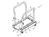
- FIG. 2 is a perspective view showing a case where the inverter stack constituting the inverter device shown in FIG. 1 is transported to the transport cart.
- FIG. 3 is a perspective view showing a case where the transport cart applied to the inverter device shown in FIGS. 1 and 2 is viewed from the front side.
- FIG. 4 is a perspective view showing a case where the transport cart applied to the inverter device shown in FIGS. 1 and 2 is viewed from the rear side.
- FIG. 5 is an enlarged perspective view showing a state where the transport cart is brought close to the switchboard.
- FIG. 1 is a perspective view showing an inverter device to which an inverter stack according to an embodiment of the present invention is applied.
- FIG. 2 is a perspective view showing a case where the inverter stack constituting the inverter device shown in FIG. 1 is transported to the transport cart.
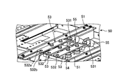
- FIG. 6 is a perspective view showing a storage bottom portion in which the inverter stack is stored in the switchboard shown in FIGS. 1 and 2.
- 7 is an enlarged perspective view showing a main part of the storage bottom shown in FIG.
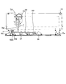
- FIG. 8 is an explanatory diagram showing a case where the storage bottom of the switchboard shown in FIG. 6 is viewed from the side.
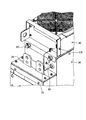
- FIG. 9 is a perspective view showing an inverter stack constituting the inverter device shown in FIGS. 1 and 2.
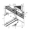
- FIG. 10 is an explanatory diagram showing the configuration of the upper surface of the inverter body.
- FIG. 11 is a perspective view showing the configuration of the fan block.
- FIG. 12 is an explanatory diagram for explaining a procedure for disposing the fan block in the inverter main body.
- FIG. 13 is an explanatory diagram for explaining a procedure for disposing the fan block in the inverter main body.
- FIG. 14 explains the procedure for disposing the fan block in the inverter main body, and is an enlarged cross-sectional view showing the main part as viewed from the front side.
- FIG. 15 explains the procedure for disposing the fan block in the inverter main body, and is an enlarged cross-sectional view showing the main part as viewed from the side.
- FIG. 16 illustrates the procedure for disposing the fan block in the inverter body, and is an enlarged cross-sectional view showing a case where the main part is viewed from the side.
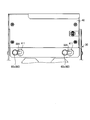
- FIG. 17 is a front view of the fan block disposed on the upper portion of the inverter main body.
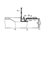
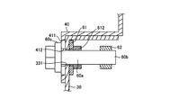
- FIG. 18 is an enlarged cross-sectional side view of the main part of the fan block disposed in the upper part of the inverter main body.
- FIG. 19 is an exploded perspective view of the main part of the fan block disposed on the upper part of the inverter body.
- FIG. 20 is an explanatory diagram for explaining a procedure for removing the fan block from the inverter main body.
- FIG. 21 is a front view for explaining the procedure for removing the fan block from the inverter main body.
- FIG. 22 is an explanatory diagram for explaining a procedure for removing the fan block from the inverter main body.
- FIG. 23 is a perspective view showing a connection state on the input side between the inverter stack and the switchboard.
- FIG. 24 is an enlarged perspective view showing the main part shown in FIG.
- FIG. 25 is a perspective view illustrating the release of the connection state on the input side between the inverter stack and the switchboard.
- FIG. 26 is a perspective view showing a connection state on the output side between the inverter stack and the switchboard.
- 27 is a perspective view showing a second output relay bar constituting the output relay bar shown in FIG.
- FIG. 28 is a side view showing a state in which the second output relay bar constituting the output relay bar shown in FIG. 26 is removed.
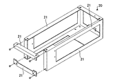
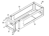
- FIG. 29 is an explanatory diagram showing the configuration of the lower frame.
- FIG. 30 is an explanatory diagram showing a configuration of a modified example of the lower frame.
- FIG. 31 is a front view showing the first output relay unit.
- FIG. 32 is a side view showing the first output relay unit.
- FIG. 33 is a perspective view of the first output relay unit as seen from the front side.
- FIG. 34 is a perspective view of the first output relay unit as seen from the rear side.
- FIG. 35 is a front view showing the second output relay unit.
- FIG. 36 is a side view showing the second output relay unit.
- FIG. 37 is a perspective view of the second output relay unit as seen from the front side.
- FIG. 38 is a perspective view of the second output relay unit as seen from the rear side.
- FIG. 39 is an explanatory view showing a state in which the first output relay unit shown in FIGS. 31 to 34 is attached.
- FIG. 40 is an explanatory view showing a state in which the second output relay unit shown in FIGS. 35 to 38 is attached.
- FIG. 39 is an explanatory view showing a state in which the first output relay unit shown in FIGS. 31 to 34 is attached.
- FIG. 40 is an explanatory view showing a state in which the second output relay unit shown in FIGS. 35 to 38 is
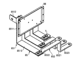
- FIG. 41 is a perspective view of an attachment member applicable to the first output relay unit shown in FIGS. 31 to 34, as viewed from the front side.
- FIG. 42 is a perspective view of an attachment member applicable to the first output relay unit shown in FIGS. 31 to 34, as viewed from the rear side.
- FIG. 43 is an explanatory view showing a state in which the attachment member shown in FIGS. 41 and 42 is applied.
- FIG. 1 is a perspective view showing an inverter device to which an inverter stack according to an embodiment of the present invention is applied.
- the inverter device exemplified here includes an inverter stack 10 and a switchboard 50.
- the inverter stack 10 is provided with an inverter circuit inside, and is transported by the transport cart 1 and installed on the target switchboard 50 as shown in FIG.
- FIGS. 3 and 4 show the transport cart 1 applied to the inverter device shown in FIGS. 1 and 2, respectively.
- FIG. 3 is a perspective view showing the transport cart 1 as viewed from the front side.
- FIG. 4 is a perspective view showing a case where the transport cart 1 is viewed from the rear side.
- the transport cart 1 is fixed to a base 2 including a plurality of cart casters 1 a (for example, four), a support surface 3, a rail guide (guide member) 4, and the like.
- a sheet metal (fixed support member) 5 and a grip portion 6 are provided.
- the support surface 3 is made of a steel plate or the like on the upper surface of the base 2, and is a surface on which a caster 10 a provided at the bottom of the inverter stack 10 can roll.
- the support surface 3 supports the inverter stack 10 in a mounted state. As shown in FIG. 5, the support surface 3 has the same height level as the two mounting surfaces 51 of the inverter stack 10 in the switchboard 50, that is, the surfaces on which the casters 10 a of the inverter stack 10 can roll. Yes.
- Such a support surface 3 is provided with a protruding portion 3a.
- the protruding portion 3 a is a plate-like portion that is formed so as to protrude rearward from the rear edge portion of the support surface 3.
- the size of the left and right width of the protruding portion 3a is adapted to the distance between the two placement surfaces 51 in the switchboard 50, and as shown in FIG. 5, the protruding portion 3a allows the transport cart 1 from the front side. When approaching, the horizontal positioning is performed by entering the entry portion 52 of the switchboard 50 formed between the placement surfaces 51.
- the rail guide 4 is a long plate-like body extending along the front-rear direction at both left and right ends of the support surface 3. These rail guides 4 are fixed to the support surface 3 with screws or the like. Such a rail guide 4 guides the rolling of the caster 10a of the inverter stack 10 when the inverter stack 10 supported in a state of being placed on the support surface 3 is moved toward the switchboard 50. The inverter stack 10 is restricted from shifting in the left-right direction.
- the fixed sheet metal 5 is a plate-like body that is provided in a manner of standing from the base 2 on the front side of the support surface 3.
- a plurality of (for example, two) screw holes 5 a are formed in the fixed sheet metal 5.
- These screw holes 5 a are respectively provided corresponding to the screw holes 10 b formed on the lower front surface of the inverter stack 10 when the inverter stack 10 is supported on the support surface 3.
- the screw N1 is inserted into both the screw hole 5a of the fixed metal plate 5 and the screw hole 10b of the inverter stack 10 from the front side, and the screw N1 is
- the stationary sheet metal 5 is fastened to the inverter stack 10 by rotating around the center and tightening.
- the fixed metal plate 5 is fixed to the inverter stack 10 by being fastened to the inverter stack 10 supported by the support surface 3 via a fastening member such as a screw N1.
- the gripping part 6 is formed on the base 2 in a form of a pair of left and right. These gripping portions 6 are formed by appropriately bending a pipe which is a long rod-like body and connecting both ends to the base 2 by welding or the like. It is for gripping.
- Reference numeral 7 in FIGS. 3 and 4 is a stopper, which is provided in the gripping portion 6.
- the inverter stack 10 placed and supported on the support surface 3 of the transport cart 1 is transported to the front side of the switchboard 50 to be installed as shown in FIG. 2, and then the transport cart 1 is switched to the switchboard. Positioning is performed by bringing the protruding portion 3 a into a predetermined entry portion 52 of the switchboard 50 in the vicinity of 50. Then, the fixing sheet metal 5 and the screw N1 inserted through the screw holes 5b and 10b of the inverter stack 10 are removed to release the fastening between the fixing sheet metal 5 and the inverter stack 10, and the inverter stack 10 is moved to move the inverter board 10 from the front side of the switchboard 50. By making it approach, it can be accommodated in the switchboard 50 as shown in FIG.
- FIG. 6 is a perspective view showing a storage bottom portion that is housed in the inverter stack 10 in the switchboard 50 shown in FIGS. 1 and 2, and FIG. 7 is an enlarged perspective view showing a main part of the storage bottom portion shown in FIG.
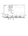
- FIG. 8 is an explanatory diagram showing a case where the storage bottom of the switchboard 50 shown in FIG. 6 is viewed from the side. As shown in FIGS. 6 to 8, the switchboard 50 includes an output relay terminal 53.
- a plurality of (for example, three) output relay terminals 53 are provided, and the U-phase output relay terminal 53, the V-phase output relay terminal 53, and the W-phase output relay terminal 53 are each in the direction in which the inverter stack 10 enters, that is, before and after
- the switchboard 50 is provided at the bottom of the switchboard 50 so as to extend along the direction and to be arranged in parallel through the insulator 54.
- Each of the output relay terminals 53 has a rear end 531 bent downward, and an output electric wire 55 connected to a load such as a motor is attached to each rear end 531.
- the output relay terminal 53 has a through hole 532a formed at each front side end 532, and a nut 532b fixedly supported on the lower surface corresponding to the through hole 532a.
- These output relay terminals 53 are located below the bottom of the inverter stack 10 to be housed, and more specifically, at a position where the height level is lower than the caster 10a of the inverter stack 10.
- FIG. 9 is a perspective view showing an inverter stack 10 constituting the inverter device shown in FIGS. 1 and 2.
- the inverter stack 10 includes a lower frame 20, an inverter body 30, and a fan block 40.
- the lower frame 20 constitutes the bottom of the inverter stack 10 and includes the above-described caster 10a.
- the lower frame 20 is formed by connecting a plurality of frame members 21 by screws or the like in a form that forms each side of a rectangular parallelepiped.
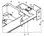
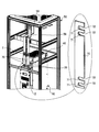
- the inverter main body 30 is a housing in which various circuits such as an inverter circuit are incorporated. As shown in FIG. 10, an opening 31 is formed on the upper surface of the inverter main body 30. Two projecting pieces 321 projecting forward are formed on the rear edge portion 32 of the upper surface of the inverter main body 30 forming such an opening 31. Further, a leaf spring member 322 is fixed to the rear edge portion 32 by fastening with a screw or the like. The leaf spring member 322 has a shape in which a front end portion 322a is bent downward, and the front end portion 322a enters a rectangular through hole 323 formed in the rear edge portion 32 from above. Yes.
- two long holes 331 whose longitudinal direction is the left-right direction are formed in the upper front surface 33 connected to the upper surface forming the opening 31.
- the body 60 a of the bolt member 60 passes through the long hole 331 from the front side, and the body 60 a that penetrates the long hole 331 is a sheet metal member that is a long plate-like body larger than the long hole 331.
- the nut 612 fixed to the sheet metal member 61 is screwed into the through hole 611 formed in the 61.
- a drop-off prevention nut 62 is fixed to the tip end portion 60b of the bolt member 60 (see FIGS. 18 and 19).
- the fan block 40 is disposed in the upper part of the inverter main body 30 and has a box shape in which a plurality of fans F for sending air to the inverter main body 30 are accommodated. As shown in FIG. 11, the fan block 40 has a rectangular parallelepiped shape with an upper surface and a lower surface opened.
- an engagement hole 41 In such a fan block 40, an engagement hole 41, a flange 42 and a locking hole 43 are formed.
- a plurality of (for example, two) engagement holes 41 are formed on the lower front surface of the fan block 40, that is, on the front surface of the portion extending downward from the extended end portion extending forward from the lower end portion of the front surface of the fan block 40. It is.
- These engagement holes 41 are such that a desorption hole portion 411 having a larger diameter than the head portion 60c of the bolt member 60 and a tightening hole portion 412 having a smaller diameter than the head portion 60c of the bolt member 60 are continuous. It is a formed Dharma hole.
- the flange 42 is formed in such a manner that it extends downward on the rear side of the left and right lower edges forming the lower surface opening 40a in the fan block 40.
- the locking hole 43 is formed on the rear surface of the fan block 40 and has a size that allows the protrusion 321 to be inserted.
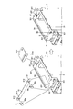
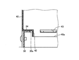
- Such a fan block 40 is arranged to be engaged with the inverter body 30 as follows. As shown in FIG. 12, the head 60c of the bolt member 60 slides on the upper surface of the inverter main body 30 with the fan block 40 facing rearward from the front side in such a manner that the head 60c relatively penetrates the attachment / detachment hole 411 of the engagement hole 41. Move. At that time, as shown in FIGS. 13 and 14, the flange 42 of the fan block 40 is located inward of the upper edge 34 of the upper surface forming the opening 31 of the inverter main body 30, and the sliding fan The block 40 is restricted from shifting more than necessary in the left-right direction.
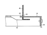
- the projecting piece 321 of the inverter main body 30 is relatively inserted into the locking hole 43 of the fan block 40, and as shown in FIG. 16, rearward from the lower end portion of the rear surface of the fan block 40.
- the rear end of the fan block 40 is engaged with the inverter body 30 by the front end 322a of the leaf spring member 322 pressing the rear extension 44 extending toward the rear with its own elastic restoring force.
- the bolt member 60 is displaced along the left-right direction so that the head 60c moves from the attachment / detachment hole portion 411 to the tightening hole portion 412, and the bolt member 60 is tightened, as shown in FIGS.
- the front side of the fan block 40 is engaged with the inverter body 30.
- the fan block 40 can be disposed on the upper portion of the inverter body 30.
- such a fan block 40 is removed from the inverter body 30 as follows. As shown in FIG. 20, the connector CN attached to the fan block 40 is removed, and the tightening force of the bolt member 60 is released. Thereafter, as shown in FIG. 21, the bolt member 60 is displaced along the left-right direction so that the head portion 60 c moves from the tightening hole portion 412 to the demounting hole portion 411. Then, as shown in FIG. 22, the fan block 40 is removed from the inverter body 30 by pulling the fan block 40 forward.
- the engaging means to make is comprised.
- the bolt member 60 and the engagement hole 41 are formed in the inverter body 30 when the bolt member 60 is tightened in a state where the body portion 60a of the bolt member 60 passes through the tightening hole portion 412 of the engagement hole 41.
- the fan block 40 is engaged, the tightening force of the bolt member 60 is released, and the bolt member 60 slides relative to the engagement hole 41 in the left-right direction so that the body portion 60a is engaged.
- the fan block 40 is allowed to be detached from the inverter main body 30 by being pulled out to the front side.
- the inverter stack 10 having such a configuration is housed and installed in the switchboard 50 as follows.
- FIG. 23 is a perspective view showing an input-side connection state between the inverter stack 10 and the switchboard 50
- FIG. 24 is an enlarged perspective view showing an enlarged main part shown in FIG.
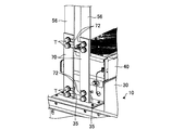
- two input terminals 35 provided on the inverter main body 30 are connected to the input-side terminals 56 of the switchboard 50 through the input relay bars 70, respectively.
- the input relay bar 70 is a plate-like member, and its upper end is fastened to the corresponding input terminal 56 of the switchboard 50 via the fastening member T, and its lower end is fastened to the corresponding input terminal 35 of the inverter stack 10. By being fastened through the member T, the input side terminal 56 and the input terminal 35 are connected as described above.
- each input relay bar 70 a hole 71 through which a bolt as a fastening member T passes is formed with a notch 72 communicating with a common side (right side or left side).
- the fastening member T can be removed without releasing the fastening force of the fastening member T as shown in FIG.
- the input relay bar 70 can be detached.
- FIG. 26 is a perspective view showing a connection state of the inverter stack 10 and the switchboard 50 on the output side.
- three output terminals (not shown) provided on the inverter main body 30 are respectively connected to the front side end portions of the output relay terminals 53 of the switchboard 50 via the output relay bars 73. 532.
- three output relay bars 73 are provided, which connect the U-phase output terminal and the U-phase output relay terminal 53, and connect the V-phase output terminal and the V-phase output relay terminal 53.
- the W-phase output terminal and the W-phase output relay terminal 53 are connected.
- Such a configuration of the output relay bar 73 has the same configuration, and includes a first output relay bar 731 and a second output relay bar 732.
- the first output relay bar 731 extends in the vertical direction, and the upper end portion is connected to the corresponding output terminal.
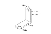
- the second output relay bar 732 has an L-shaped longitudinal section, and more specifically has a base 7321 and a tip 7322.
- the base portion 7321 extends along the vertical direction and protrudes downward from the bottom portion of the inverter stack 10, and its upper end portion is fastened to the lower end portion of the first output relay bar 731 via the fastening member T. It is.
- the distal end portion 7322 is a portion extending forward from the lower end portion of the base portion 7321, and is fastened to the front side end portion 532 of the corresponding output relay terminal 53 via the fastening member T.
- the output relay terminal 53 provided on the switchboard 50 has the output wire 55 connected to a load such as a motor attached to the rear side end portion 531, and the front side end portion 532 serves as the output terminal of the inverter stack 10.
- the output relay bar 73 that is connected and protrudes downward from the bottom of the inverter stack 10 is fastened via a fastening member T.
- the insertion hole 7321 a through which the fastening member T is inserted in the base portion 7321 and the insertion hole 7322 a through which the fastening member T is inserted in the distal end portion 7322 are larger than the outer diameter of the fastening member T. It is formed to have a diameter.
- the inverter stack 10 is driven by removing the second output relay bar 732 from both the first output relay bar 731 and the corresponding output relay terminal 53. Inverter unit to be tested can be started up.
- the lower frame 20 Since the output relay bar 73 is provided so as to penetrate the lower frame 20 of the inverter stack 10, the lower frame 20 has a quadrilateral frame that penetrates the output relay bar 73 as shown in FIG.
- the frame material 21 constituting one side that is, the frame material 21 constituting the front upper side and the frame material 21 constituting the front lower side are formed of a nonmagnetic material such as stainless steel, and the other frame material 21 is made of sheet metal or the like. It is formed by.
- the generation of eddy current can be regulated by forming the frame material 21 constituting one side of the four-circumferential frame through which the output relay bar 73 penetrates with a non-magnetic material.
- the frame material 21 constituting the front upper side and the frame material 21 constituting the front lower side are formed of a non-magnetic material as one side of the four-circumferential frame penetrating the output relay bar 73.
- a pair of left and right front side vertical members that connect the frame material 21 constituting the front upper side and the frame material 21 constituting the front lower side may be formed of a nonmagnetic material such as stainless steel.
- the generation of eddy currents can be restricted by forming the frame material 21 constituting one side of the four-circumferential frame through which the output relay bar 73 penetrates with a non-magnetic material.
- the output relay bar 73 is used as an output relay unit, and the U-phase output terminal and the U-phase output relay terminal 53 are connected, and the V-phase output terminal and the V-phase output relay terminal 53 are connected.
- the first output relay unit 80 and the first output relay unit 80 are connected in place of the output relay bar 73. Any one of the two-output relay units 90 selected as an output relay unit may be used.
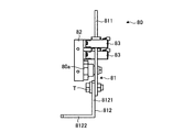
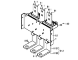
- FIG. 31 to 34 show the first output relay unit 80, respectively.
- FIG. 31 is a front view
- FIG. 32 is a side view
- FIG. 33 is a perspective view seen from the front side
- the first output relay unit 80 illustrated here includes three output relay bars 81 and a fixed metal 82.
- the three output relay bars 81 respectively connect the U-phase output terminal and the U-phase output relay terminal 53, connect the V-phase output terminal and the V-phase output relay terminal 53, and the W-phase output relay terminal 53.
- the output terminal is connected to the W-phase output relay terminal 53.
- These three output relay bars 81 include a first output relay bar 811 and a second output relay bar 812.
- the first output relay bar 811 extends along the vertical direction, and its upper end can be connected to a corresponding output terminal.
- the second output relay bar 812 has an L-shaped longitudinal section, and more specifically has a base portion 8121 and a tip portion 8122.
- the base 8121 extends along the vertical direction, and the upper end thereof is fastened to the lower end of the first output relay bar 811 via the fastening member T.
- the distal end portion 8122 is a portion that extends forward from the lower end portion of the base portion 8121, and can be fastened to the front side end portion 532 of the corresponding output relay terminal 53 via the fastening member T.
- an insertion hole (not shown) through which the fastening member T in the base 8121 is inserted, and an insertion hole 8122a through which the fastening member T is inserted in the distal end portion 8122 are the outer diameter of the fastening member T. It is formed to have a larger diameter than that.
- the fixed metal 82 is formed by bending a sheet metal as appropriate, and is integrally connected to the three output relay bars 81 via a resin 80a that is an insulating member. Such a fixed metal 82 is for fixing to the inverter stack 10.
- reference numeral 83 denotes a hall CT that detects current.
- the first output relay unit 80 Since the first output relay unit 80 has three output relay bars 81, it can output the three-phase output from the output terminal to the output relay terminal 53 as it is.
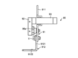
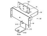
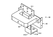
- FIG. 35 to 38 respectively show the second output relay unit 90.
- FIG. 35 is a front view
- FIG. 36 is a side view
- FIG. 37 is a perspective view seen from the front side
- FIG. 38 is seen from the rear side.
- FIG. 35 is a front view
- FIG. 36 is a side view
- FIG. 37 is a perspective view seen from the front side
- FIG. 38 is seen from the rear side.
- the second output relay unit 90 exemplified here includes one output relay bar 91 and a fixed metal 92.
- the output relay bar 91 includes a first output relay bar 911 and a second output relay bar 912.
- the first output relay bar 911 extends along the vertical direction, and its upper end can be connected to three output terminals.
- the second output relay bar 912 has an L-shaped longitudinal section, and more specifically has a base portion 9121 and a tip portion 9122.
- the base portion 9121 extends along the vertical direction, and the upper end portion thereof is fastened to the lower end portion of the first output relay bar 911 via the fastening member T.
- the distal end portion 9122 is a portion extending forward from the lower end portion of the base portion 9121, and can be fastened to the front side end portion 532 of any one of the output relay terminals 53 via the fastening member T.
- an insertion hole (not shown) through which the fastening member T is inserted in the base portion 9121 and an insertion hole 9122a through which the fastening member T is inserted in the distal end portion 9122 are the outer diameter of the fastening member T. It is formed to have a larger diameter than that.
- the fixed metal 92 is formed by appropriately bending a sheet metal, and is integrally connected to the output relay bar 91 via a resin 90a that is an insulating member. Such a fixed metal 92 is for fixing to the inverter stack 10.
- reference numeral 93 in FIGS. 35 to 38 denotes a hole CT, which detects current.
- the second output relay unit 90 Since the second output relay unit 90 has one output relay bar 91, the three-phase output from the output terminal is set as one of the U phase, the V phase, and the W phase. It can output to the output relay terminal 53.
- the first output relay is performed by fixing the output stack bar 81 to the output frame and the output relay terminal 53 by fixing the output stack bar 81 to the lower frame 20 of the inverter stack 10 via the fixed metal 82.
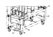
- the unit 80 may be used as an output relay unit, and as shown in FIG. 40, the unit 80 is fixed to the lower frame 20 of the inverter stack 10 via a fixing metal 92, and the output relay bar 91, each output terminal, and any one of The second output relay unit 90 may be used as the output relay unit by fastening the output relay terminal 53.
- the support surface 3 that supports the inverter stack 10 in a state where the inverter stack 10 is placed has the same height level as the placement surface 51 of the inverter stack 10 in the switchboard 50 to be installed.
- the protrusion 3a provided in such a manner as to protrude outward from the support surface 3 enters the entry portion 52 formed between the placement surfaces 51 of the switchboard 50 to perform horizontal positioning. Therefore, it does not require high alignment accuracy unlike the conventional lifter.
- the rail guides 4 arranged along the direction in which the inverter stack 10 can move on the support surface 3 can move to the left and right with respect to the moving direction when the inverter stack 10 is moved. Since the displacement in the direction is restricted, the installation work of the inverter stack 10 can be performed satisfactorily.
- the fixed sheet metal 5 erected from the support surface 3 is fastened to the inverter stack 10 supported by the support surface 3 via a fastening member such as a screw N 1. Since the inverter stack 10 is fixedly supported, the inverter stack 10 can be prevented from falling during transportation.
- the gripping portion 6 is provided on the base 2 having the support surface 3 in a pair of left and right, so that the inverter stack 10 can be transported well even in a narrow passage. Is possible.
- the fan block 40 is engaged with the inverter body 30.
- the tightening force of the bolt member 60 is released, and the bolt member 60 slides relative to the engagement hole 41 in the left-right direction, so that the body portion 60a is detached from the engagement hole 41.
- the fan block 40 is pulled out to the front side to allow the fan block 40 to be detached from the inverter main body 30. Therefore, even when the storage area where the inverter stack 10 is installed is narrow, the fan block 40 40 can be detached from the inverter main body 30 and the fan block 40 can be easily taken out.
- the drop prevention nut 62 is fixed to the tip end portion 60 b of the bolt member 60, so that the bolt member 60 does not fall even when the tightening force of the bolt member 60 is released. Therefore, the bolt member 60 can be prevented from dropping when the fan block 40 is detached from the inverter main body 30.
- the protruding piece 321 of the inverter main body 30 is inserted into the locking hole 43 of the fan block 40, and further Since the rearward extending portion 44 of the block 40 is pressed by the leaf spring member 322 attached to the inverter main body 30, it is only necessary to push the fan block 40 rearward, and the installation work of the fan block 40 can be improved.
- the output relay terminal 53 is provided in a manner that extends along the entry direction of the inverter stack 10 at the storage bottom portion where the inverter stack 10 is stored, and a motor or the like is provided on the rear side end portion 531 thereof.
- the output electric wire 55 connected to the load is attached, and the front side end portion 532 is connected to the output terminal of the inverter stack 10 and fastened to the output relay bar 73 protruding downward from the bottom portion of the inverter stack 10. Since it is fastened via the member T, the connection state on the output side between the inverter stack 10 and the switchboard 50 can be released simply by releasing the fastening between the output relay terminal 53 and the output relay bar 73. Therefore, according to the inverter device, the inverter stack 10 can be easily detached from the switchboard 50.
- the input relay bar 70 allows the fastening member T such as a bolt to be inserted into the hole 71 in which the notch 72 communicating with the common side portion is formed. By releasing, the input relay bar 70 can be detached without removing the fastening member T, and the connection state on the input side between the inverter stack 10 and the switchboard 50 can be released. Therefore, the inverter stack 10 can be easily detached from the switchboard 50 by this.
- the lower frame 20 constituting the inverter stack 10 is formed of the non-magnetic material for the frame material 21 constituting one side of the four-circumferential frame penetrating the output relay bar 73.
- Generation of electric current can be regulated, and thereby heating and vibration due to generation of eddy current can be prevented.
- the other frame members 21 of the lower frame 20 are made of sheet metal or the like, the manufacturing cost can be reduced as compared with the case where all the frame members are made of a nonmagnetic material such as stainless steel. Therefore, it is possible to reduce the manufacturing cost while preventing heating and vibration due to generation of eddy current or the like.
- the non-magnetic frame material 21 is replaced with a frame material formed of a magnetic material such as a sheet metal. Also good. When it is clear that eddy current does not occur in this way, the operation cost can be reduced by configuring all the frame members 21 constituting the lower frame 20 with a magnetic material.
- an output relay unit that is alternatively selected from the first output relay unit 80 and the second output relay unit 90 can be used. Therefore, it is possible to easily change the configuration of the output terminal that connects the inverter stack 10 and the switchboard 50.
- the output relay unit is selected from the first output relay unit 80 and the second output relay unit 90, but in the present invention, the first output relay unit is used.
- a member having the following attachment member 84 may be used.
- FIGS. 31 to 34 show an attachment member 84 applicable to the first output relay unit 80 shown in FIGS. 31 to 34, respectively.
- FIG. 41 is a perspective view seen from the front side, and FIG. It is the perspective view seen from the side.
- the attachment member 84 exemplified here includes three output relay attachment bars 85.
- These three output relay attachment bars 85 include a first output relay attachment bar 851 and a second output relay attachment bar 852.
- the first output relay attachment bar 851 includes a first base 8511 extending along the vertical direction, a right extension 8512 extending rightward from the upper end of the first base 8511, and a first base 8511.
- the first base portion 8511 is connected to the attachment fixing metal 86 via a resin 84a that is an insulating member.
- the second output relay attachment bar 852 includes a second base portion 8521 extending along the vertical direction, a rear extension portion 8522 extending rearward from the upper end portion of the second base portion 8521, and a lower end portion of the second base portion 8521.
- the rear extending portion 8522 is fastened to the left extending portion 8513 of the first output relay attachment bar 851 via the fastening member T.
- the front extending portion 8523 extends further forward.
- such an attachment member 84 fixes the attachment fixing metal 86 to the lower frame 20 of the inverter stack 10, and the second extension relay 8523 corresponding to each second output relay attachment bar 852. It is used by fastening the front end portion 8122 of the output relay bar 812 via the fastening member T.
- the first output relay unit 80 including such an attachment member 84 as an output relay unit, it is possible to flexibly respond to customer requests and changes in specifications.
Landscapes
- Engineering & Computer Science (AREA)
- Microelectronics & Electronic Packaging (AREA)
- Physics & Mathematics (AREA)
- Thermal Sciences (AREA)
- Inverter Devices (AREA)
- Casings For Electric Apparatus (AREA)
- Cooling Or The Like Of Electrical Apparatus (AREA)
Abstract
Description
1a カート用キャスタ
2 基台
3 支持面
3a 突出部
4 レールガイド(ガイド部材)
5 固定板金(固定支持部材)
5a ネジ孔
6 把持部
10 インバータスタック
10a キャスタ
20 下部フレーム
21 フレーム材
30 インバータ本体
31 開口
32 後縁部
321 突片
322 板バネ部材
322a 先端部
323 貫通孔
33 上部前面
331 長孔
34 上側縁部
35 入力端子
40 ファンブロック
40a 下面開口
41 係合孔
411 脱着孔部
412 締付孔部
42 フランジ
43 係止孔
44 後延部
50 配電盤
51 載置面
52 進入部
53 出力中継端子
531 背面側端部
532 正面側端部
532a 貫通孔
532b ナット
54 碍子
55 出力電線
56 入力側端子
60 ボルト部材
60a 胴部
60b 先端部
60c 頭部
61 板金部材
611 貫通孔
612 ナット
62 脱落防止用ナット
70 入力中継バー
71 孔部
72 切欠
73 出力中継バー
731 第1出力中継バー
732 第2出力中継バー
7321 基部
7322 先端部
7321a 挿通孔
7322a 挿通孔
80 第1出力中継ユニット
81 出力中継バー
80a 樹脂
811 第1出力中継バー
812 第2出力中継バー
8121 基部
8122 先端部
8122a 挿通孔
82 固定金
84 アタッチメント部材
84a 樹脂
85 出力中継アタッチメントバー
851 第1出力中継アタッチメントバー
8511 第1基部
8512 右延部
8513 左延部
852 第2出力中継アタッチメントバー
8521 第2基部
8522 後延部
8523 前延部
86 アタッチメント固定金
90 第2出力中継ユニット
90a 樹脂
91 出力中継バー
911 第1出力中継バー
912 第2出力中継バー
9121 基部
9122 先端部
9122a 挿通孔
92 固定金
F ファン
T 締結部材
Claims (3)
- 内部にインバータ回路が収納された筐体であるインバータ本体と、
前記インバータ本体の上部に係合手段を介して配設され、内部にインバータ本体に空気を送出するための複数のファンが収納された箱状のファンブロックと
を備えたインバータスタックにおいて、
前記係合手段は、
前記インバータ本体の上部前面に形成された左右方向が長手方向となる長孔を前方側から貫通し、この長孔を貫通した胴部が該長孔よりも大きい板金部材に形成された貫通孔を貫通する態様で該板金部材に固定されたナット部材に螺合するとともに、先端部に脱落防止用ナットが固定されたボルト部材と、
前記ファンブロックの下部前面に形成され、かつ前記ボルト部材の頭部の外径よりも大径となる脱着孔部と、前記ボルト部材の頭部の外径よりも小径となる締付孔部とが連続する態様で形成された係合孔と
を備え、
前記ボルト部材の胴部が前記係合孔の締付孔部を貫通する状態で該ボルト部材が締め付けられる場合には、前記インバータ本体に前記ファンブロックを係合する一方、前記ボルト部材の締め付け力が解除されて該ボルト部材が前記係合孔に対して相対的に左右方向に沿ってスライド移動することで前記胴部が前記係合孔の脱着孔部を貫通する場合には、前記ファンブロックが前方側に引き出されることで前記インバータ本体から離脱することを許容することを特徴とするインバータスタック。 - 前記係合手段は、
前記インバータ本体の上部後方側において前方に向けて突出する突片と、
前記ファンブロックの後面に形成され、かつ前記突片が相対的に挿通することを許容する係止孔と
を備えたことを特徴とする請求項1に記載のインバータスタック。 - 前記係合手段は、
前記インバータ本体の上部後方側に配設され、かつ前記ファンブロックの後面の下端部より後方に向けて延在する後延部を自身の弾性復元力にて押さえつける板バネ部材を備えたことを特徴とする請求項1又は請求項2に記載のインバータスタック。
Priority Applications (3)
| Application Number | Priority Date | Filing Date | Title |
|---|---|---|---|
| DE112012002177.0T DE112012002177B4 (de) | 2011-10-31 | 2012-10-26 | Umrichterstapel |
| US14/131,066 US8993901B2 (en) | 2011-10-31 | 2012-10-26 | Inverter stack |
| CN201280032647.1A CN103636114B (zh) | 2011-10-31 | 2012-10-26 | 逆变器叠堆 |
Applications Claiming Priority (2)
| Application Number | Priority Date | Filing Date | Title |
|---|---|---|---|
| JP2011-239645 | 2011-10-31 | ||
| JP2011239645A JP5782994B2 (ja) | 2011-10-31 | 2011-10-31 | インバータスタック |
Publications (1)
| Publication Number | Publication Date |
|---|---|
| WO2013065604A1 true WO2013065604A1 (ja) | 2013-05-10 |
Family
ID=48191953
Family Applications (1)
| Application Number | Title | Priority Date | Filing Date |
|---|---|---|---|
| PCT/JP2012/077753 Ceased WO2013065604A1 (ja) | 2011-10-31 | 2012-10-26 | インバータスタック |
Country Status (5)
| Country | Link |
|---|---|
| US (1) | US8993901B2 (ja) |
| JP (1) | JP5782994B2 (ja) |
| CN (1) | CN103636114B (ja) |
| DE (1) | DE112012002177B4 (ja) |
| WO (1) | WO2013065604A1 (ja) |
Families Citing this family (9)
| Publication number | Priority date | Publication date | Assignee | Title |
|---|---|---|---|---|
| CN103687414B (zh) * | 2012-08-30 | 2016-12-21 | 台达电子工业股份有限公司 | 大功率机柜散热系统及静止无功补偿系统 |
| CN103683845B (zh) * | 2012-08-30 | 2016-04-13 | 台达电子工业股份有限公司 | 散热型功率变换器装置 |
| JP2015050257A (ja) * | 2013-08-30 | 2015-03-16 | 株式会社東芝 | 車両用電力変換装置及び鉄道車両 |
| KR102206389B1 (ko) * | 2014-12-08 | 2021-01-22 | 엘에스일렉트릭(주) | 태양광 인버터 스택 |
| JP6399954B2 (ja) * | 2015-03-10 | 2018-10-03 | 三菱電機株式会社 | モータ駆動装置 |
| JP6518186B2 (ja) * | 2015-12-17 | 2019-05-22 | 株式会社日立製作所 | 電力変換器用筐体および筐体付の電力変換器 |
| JP6804147B2 (ja) * | 2016-11-28 | 2020-12-23 | 住友重機械工業株式会社 | 作業機械及び電力変換装置 |
| JP6613284B2 (ja) * | 2017-10-31 | 2019-11-27 | ファナック株式会社 | ファンユニット |
| JP7404961B2 (ja) * | 2020-03-23 | 2023-12-26 | 株式会社明電舎 | 風洞構造及び電力変換装置 |
Citations (5)
| Publication number | Priority date | Publication date | Assignee | Title |
|---|---|---|---|---|
| JPH02204700A (ja) * | 1989-01-31 | 1990-08-14 | Fuji Electric Co Ltd | 冷却ファンの取付装置 |
| JP2005064046A (ja) * | 2003-08-13 | 2005-03-10 | Fuji Electric Fa Components & Systems Co Ltd | ファン実装構造 |
| JP2006020500A (ja) * | 2005-09-09 | 2006-01-19 | Fuji Electric Fa Components & Systems Co Ltd | 電力変換装置の主回路端子構造 |
| JP2007325383A (ja) * | 2006-05-31 | 2007-12-13 | Fuji Electric Fa Components & Systems Co Ltd | インバータ装置 |
| JP2010098858A (ja) * | 2008-10-16 | 2010-04-30 | Fuji Electric Systems Co Ltd | インバータ装置 |
Family Cites Families (14)
| Publication number | Priority date | Publication date | Assignee | Title |
|---|---|---|---|---|
| JPH07123539A (ja) * | 1993-10-29 | 1995-05-12 | Fuji Electric Co Ltd | 大容量インバータの着脱装置 |
| DE19636094A1 (de) * | 1996-05-21 | 1997-11-27 | Siemens Ag | Luftgekühlter Umrichter im Megawattbereich |
| JPH10308589A (ja) * | 1997-05-09 | 1998-11-17 | Saitama Nippon Denki Kk | 冷却ファン装置 |
| IL146838A0 (en) * | 2001-11-29 | 2002-07-25 | Active Cool Ltd | Active cooling system for cpu |
| ES2377018T3 (es) * | 2004-06-24 | 2012-03-21 | Sma Solar Technology Ag | Inversor con una carcasa con componentes eléctricos y/o electrónicos presentando disipadores de calor |
| US7088583B2 (en) * | 2004-10-25 | 2006-08-08 | International Business Machines Corporation | System for airflow management in electronic enclosures |
| DE202006008792U1 (de) * | 2006-06-01 | 2007-10-04 | Diehl Ako Stiftung & Co. Kg | Solarwechselrichter |
| JP4662315B2 (ja) * | 2009-05-20 | 2011-03-30 | 株式会社安川電機 | ファンユニットとこれを備えた電子機器装置 |
| JP5418847B2 (ja) * | 2009-08-04 | 2014-02-19 | 株式会社安川電機 | 電力変換装置 |
| CN201622108U (zh) * | 2010-02-03 | 2010-11-03 | 徐州派特控制技术有限公司 | 弯板传感器框架 |
| CN201742668U (zh) * | 2010-05-11 | 2011-02-09 | 深圳市汇川技术股份有限公司 | 模块化组件安装结构 |
| US8325479B2 (en) * | 2010-07-16 | 2012-12-04 | Rockwell Automation Technologies, Inc. | Motor drive cooling duct system and method |
| JP5803327B2 (ja) * | 2011-06-27 | 2015-11-04 | 富士電機株式会社 | インバータ装置の防水カバー |
| US8634193B2 (en) * | 2011-12-05 | 2014-01-21 | Rockwell Automation Technologies, Inc. | Device and method using induction to improve natural convection cooling |
-
2011
- 2011-10-31 JP JP2011239645A patent/JP5782994B2/ja active Active
-
2012
- 2012-10-26 US US14/131,066 patent/US8993901B2/en active Active
- 2012-10-26 WO PCT/JP2012/077753 patent/WO2013065604A1/ja not_active Ceased
- 2012-10-26 CN CN201280032647.1A patent/CN103636114B/zh active Active
- 2012-10-26 DE DE112012002177.0T patent/DE112012002177B4/de active Active
Patent Citations (5)
| Publication number | Priority date | Publication date | Assignee | Title |
|---|---|---|---|---|
| JPH02204700A (ja) * | 1989-01-31 | 1990-08-14 | Fuji Electric Co Ltd | 冷却ファンの取付装置 |
| JP2005064046A (ja) * | 2003-08-13 | 2005-03-10 | Fuji Electric Fa Components & Systems Co Ltd | ファン実装構造 |
| JP2006020500A (ja) * | 2005-09-09 | 2006-01-19 | Fuji Electric Fa Components & Systems Co Ltd | 電力変換装置の主回路端子構造 |
| JP2007325383A (ja) * | 2006-05-31 | 2007-12-13 | Fuji Electric Fa Components & Systems Co Ltd | インバータ装置 |
| JP2010098858A (ja) * | 2008-10-16 | 2010-04-30 | Fuji Electric Systems Co Ltd | インバータ装置 |
Also Published As
| Publication number | Publication date |
|---|---|
| JP2013099113A (ja) | 2013-05-20 |
| US20140233291A1 (en) | 2014-08-21 |
| DE112012002177T5 (de) | 2014-02-20 |
| US8993901B2 (en) | 2015-03-31 |
| CN103636114A (zh) | 2014-03-12 |
| JP5782994B2 (ja) | 2015-09-24 |
| DE112012002177B4 (de) | 2021-05-20 |
| CN103636114B (zh) | 2019-01-25 |
Similar Documents
| Publication | Publication Date | Title |
|---|---|---|
| JP5782995B2 (ja) | インバータ装置 | |
| JP5895452B2 (ja) | インバータ装置 | |
| JP5782994B2 (ja) | インバータスタック | |
| CN102545084B (zh) | 结合电路断路器使用的底架和键锁组件以及开关装置 | |
| WO2013065602A1 (ja) | 運搬用カート | |
| JP5821534B2 (ja) | インバータ装置 | |
| CN103636115B (zh) | 逆变器装置 | |
| JP4760429B2 (ja) | 電気機器のレール取付け構造 | |
| JP5889015B2 (ja) | 遮断器 | |
| JP6123910B2 (ja) | 電力変換装置 | |
| KR101580446B1 (ko) | 마운팅 플레이트 상의 특히 보호 회로를 위한 스타델타 와이어링 | |
| JP5274988B2 (ja) | 機器取付構造 | |
| JP4625381B2 (ja) | 配電盤 | |
| JP2017169379A (ja) | コネクタの保持材 | |
| KR20140003547U (ko) | 전장박스 조립구조 | |
| JP2001078330A (ja) | 電気接続箱の取付構造 |
Legal Events
| Date | Code | Title | Description |
|---|---|---|---|
| 121 | Ep: the epo has been informed by wipo that ep was designated in this application |
Ref document number: 12846364 Country of ref document: EP Kind code of ref document: A1 |
|
| WWE | Wipo information: entry into national phase |
Ref document number: 1120120021770 Country of ref document: DE Ref document number: 112012002177 Country of ref document: DE |
|
| WWE | Wipo information: entry into national phase |
Ref document number: 14131066 Country of ref document: US |
|
| 122 | Ep: pct application non-entry in european phase |
Ref document number: 12846364 Country of ref document: EP Kind code of ref document: A1 |