WO2013065555A1 - 車両玩具 - Google Patents
車両玩具 Download PDFInfo
- Publication number
- WO2013065555A1 WO2013065555A1 PCT/JP2012/077497 JP2012077497W WO2013065555A1 WO 2013065555 A1 WO2013065555 A1 WO 2013065555A1 JP 2012077497 W JP2012077497 W JP 2012077497W WO 2013065555 A1 WO2013065555 A1 WO 2013065555A1
- Authority
- WO
- WIPO (PCT)
- Prior art keywords
- vehicle
- chassis
- constitutes
- surface member
- connecting means
- Prior art date
- Legal status (The legal status is an assumption and is not a legal conclusion. Google has not performed a legal analysis and makes no representation as to the accuracy of the status listed.)
- Ceased
Links
Images



Classifications
-
- A—HUMAN NECESSITIES
- A63—SPORTS; GAMES; AMUSEMENTS
- A63H—TOYS, e.g. TOPS, DOLLS, HOOPS OR BUILDING BLOCKS
- A63H17/00—Toy vehicles, e.g. with self-drive; ; Cranes, winches or the like; Accessories therefor
-
- A—HUMAN NECESSITIES
- A63—SPORTS; GAMES; AMUSEMENTS
- A63H—TOYS, e.g. TOPS, DOLLS, HOOPS OR BUILDING BLOCKS
- A63H17/00—Toy vehicles, e.g. with self-drive; ; Cranes, winches or the like; Accessories therefor
- A63H17/004—Stunt-cars, e.g. lifting front wheels, roll-over or invertible cars
-
- A—HUMAN NECESSITIES
- A63—SPORTS; GAMES; AMUSEMENTS
- A63H—TOYS, e.g. TOPS, DOLLS, HOOPS OR BUILDING BLOCKS
- A63H17/00—Toy vehicles, e.g. with self-drive; ; Cranes, winches or the like; Accessories therefor
- A63H17/05—Trucks; Lorries
-
- A—HUMAN NECESSITIES
- A63—SPORTS; GAMES; AMUSEMENTS
- A63H—TOYS, e.g. TOPS, DOLLS, HOOPS OR BUILDING BLOCKS
- A63H17/00—Toy vehicles, e.g. with self-drive; ; Cranes, winches or the like; Accessories therefor
- A63H17/26—Details; Accessories
Definitions
- the present invention relates to a vehicle toy, and more particularly, to a vehicle toy that changes from a vehicle in a first form to a vehicle in a second form different from the first form.
- a conventional vehicle toy has a plurality of members with different appearances on the front and back, and an operator rotates each member to reverse the front and back of each member to change the vehicle toy to have a different appearance.
- Patent Document 1 A conventional vehicle toy has a plurality of members with different appearances on the front and back, and an operator rotates each member to reverse the front and back of each member to change the vehicle toy to have a different appearance.
- a body side wall, a body front surface, and a body rear surface are attached to a support frame so as to be rotatable up and down.
- the operator can change the appearance of the vehicle toy by turning the body side wall, the body front surface, and the body rear surface upward.
- Patent Document 1 in order to change the appearance of the vehicle, it is necessary to individually rotate the body side wall, the body front surface, and the body rear surface.
- the infant who is the main user of the toy has a problem that it is difficult to change the appearance of the vehicle because the operation is complicated.
- the body side wall, the body front surface, etc. as large as possible.
- the support frame since the body side wall and the front surface of the body are attached to the support frame, if the body side wall and the front surface of the body are formed large, the support frame is necessarily thinned. When the support frame is thin, it is impossible to ensure the strength required for the toy used by the infant.
- an object of the present invention is to provide a vehicle toy that can easily change its appearance and that can obtain high strength.
- a vehicle toy according to the present invention is a vehicle toy that changes between a first form and a second form.
- the vehicle toy is provided above a chassis that forms a lower part of the vehicle, and the surface of the vehicle toy is the first.
- the vehicle upper surface in the first embodiment is configured such that the rear surface is rotatably connected to the upper surface member configuring the vehicle upper surface in the second embodiment and the front portion of the upper surface member, and the surface is the vehicle in the first embodiment.
- the connecting means includes the upper surface member. And a reversing rotation shaft for rotatably supporting the upper surface member in a direction for reversing the front and back surfaces.
- a vehicle toy according to the present invention is a vehicle toy that changes between a first form and a second form, and is provided on a chassis constituting a lower part of the vehicle, above the chassis, and the surface thereof is the first form.
- the rear surface of the vehicle is configured to be pivotally connected to the rear surface of the upper surface member and the upper surface member that configures the upper surface of the vehicle in the second mode, and the surface is the rear surface of the vehicle in the first mode.
- a rear surface member constituting the rear surface of the vehicle in the second embodiment, and a connecting means for connecting a front portion of the upper surface member to the chassis, the connecting means is the upper surface member.
- a reversing rotation shaft for rotatably supporting the upper surface member in a direction for reversing the front and back surfaces.
- the vehicle toy of the present invention in the configuration of (1) or (2), the vehicle toy is rotatably connected to the side portion of the upper surface member, and the surface constitutes the vehicle side surface in the first mode.
- the back surface has a side member constituting the vehicle side surface in the second embodiment.
- the vehicle toy according to the present invention is a vehicle toy that changes between a first form and a second form, and is provided on a chassis constituting a lower part of the vehicle, above the chassis, and a surface thereof is the first form.
- the vehicle upper surface in the first embodiment is configured such that the rear surface is rotatably connected to the upper surface member configuring the vehicle upper surface in the second embodiment and the side portion of the upper surface member, and the surface is the vehicle in the first embodiment.
- the vehicle toy according to the present invention is a vehicle toy that changes between a first form and a second form, and is provided on a chassis constituting a lower part of the vehicle, above the chassis, and the surface thereof is the first form.
- the upper surface of the vehicle in the second embodiment, the upper surface member constituting the upper surface of the vehicle in the second embodiment, and connecting means for connecting the upper surface member to the chassis, the connecting means, A separation rotation shaft that rotatably supports the upper surface member in a direction away from the chassis, and a reversal rotation shaft that rotatably supports the upper surface member in a direction of reversing the front and back.
- a gear-like engaged body provided on the outer periphery of the reversing rotation shaft, and a valley portion of the engaged body
- the claw portion rotates along the valley portion and the mountain portion while overcoming the mountain portion of the engaged body
- the vehicle toy according to the present invention is a vehicle toy that changes between a first form and a second form, and is provided on a chassis constituting a lower part of the vehicle, above the chassis, and the surface thereof is the first form.
- the vehicle upper surface in the first embodiment is configured such that the rear surface is rotatably connected to the upper surface member configuring the vehicle upper surface in the second embodiment and the front portion of the upper surface member, and the surface is the vehicle in the first embodiment.
- the connecting means includes the upper surface member.
- a spherical part provided on one of the chassis and a holding part provided on the other side for rotatably supporting the spherical part, and the upper surface member can be rotated in a direction away from the chassis.
- the top member is turned upside down. It is characterized in that it is supported so as to be rotatable in the direction of movement.
- the vehicle toy according to the present invention is a vehicle toy that changes between a first form and a second form, and is provided on a chassis constituting a lower part of the vehicle, above the chassis, and the surface thereof is the first form.
- the rear surface of the vehicle is configured to be pivotally connected to the rear surface of the upper surface member and the upper surface member that configures the upper surface of the vehicle in the second mode, and the surface is the rear surface of the vehicle in the first mode.
- a rear surface member constituting the rear surface of the vehicle in the second embodiment, and a connecting means for connecting a front portion of the upper surface member to the chassis, the connecting means is the upper surface member.
- a spherical part provided on one of the chassis and a holding part provided on the other side for rotatably supporting the spherical part, and the upper surface member can be rotated in a direction away from the chassis.
- the top member is turned upside down. It is characterized in that it is supported so as to be rotatable in the direction of movement.
- the vehicle toy in the configuration of (7) or (8), is rotatably connected to the side portion of the upper surface member, and the surface constitutes the vehicle side surface in the first mode.
- the back surface has a side member constituting the vehicle side surface in the second embodiment.
- a vehicle toy according to the present invention is a vehicle toy that changes between a first form and a second form, and is provided on a chassis constituting a lower part of the vehicle, above the chassis, and the surface thereof is the first form.
- the vehicle upper surface in the first embodiment is configured such that the rear surface is rotatably connected to the upper surface member configuring the vehicle upper surface in the second embodiment and the side portion of the upper surface member, and the surface is the vehicle in the first embodiment.
- the coupling unit includes the upper surface member and the It consists of a spherical part provided on one of the chassis and a holding part that is provided on the other and holds the spherical part in a rotatable manner, and supports the upper surface member in a direction away from the chassis. And the upper surface member is turned upside down. It is characterized by being supported so as to be rotatable in the direction of rotation.
- the vehicle toy according to the present invention is a vehicle toy that changes between a first form and a second form.
- the vehicle toy is provided above the chassis and a chassis that forms a lower part of the vehicle.
- the upper surface member that is movably supported and is supported so as to be rotatable in a direction in which the upper and lower surfaces are separated from each other.
- a vehicle toy according to the present invention is a vehicle toy that changes between a first form and a second form, and is provided on a chassis constituting a lower part of the vehicle, above the chassis, and the surface thereof is the first form.
- the vehicle upper surface in the first embodiment is configured such that the rear surface is rotatably connected to the upper surface member configuring the vehicle upper surface in the second embodiment and the front portion of the upper surface member, and the surface is the vehicle in the first embodiment.
- the connecting means includes the upper surface member.
- a foldable thin plate portion that rotatably supports in a direction away from the chassis, and a reversing rotation shaft that rotatably supports the upper surface member in a direction in which the upper and lower surfaces are reversed.
- the vehicle toy according to the present invention is a vehicle toy that changes between a first form and a second form, and is provided on a chassis constituting a lower part of the vehicle, above the chassis, and the surface thereof is the first form.
- the rear surface of the vehicle is configured to be pivotally connected to the rear surface of the upper surface member and the upper surface member that configures the upper surface of the vehicle in the second mode, and the surface is the rear surface of the vehicle in the first mode.
- a rear surface member constituting the rear surface of the vehicle in the second embodiment, and a connecting means for connecting a front portion of the upper surface member to the chassis, the connecting means is the upper surface member.
- a foldable thin plate portion that rotatably supports in a direction away from the chassis, and a reversing rotation shaft that rotatably supports the upper surface member in a direction in which the upper and lower surfaces are reversed.
- the vehicle toy in the configuration of (12) or (13), the vehicle toy is rotatably connected to the side portion of the upper surface member, and the surface constitutes the vehicle side surface in the first mode.
- the back surface has a side member constituting the vehicle side surface in the second embodiment.
- a vehicle toy according to the present invention is a vehicle toy that changes between a first form and a second form, and is provided on a chassis constituting a lower part of the vehicle, above the chassis, and the surface thereof is the first form.
- the vehicle upper surface in the first embodiment is configured such that the rear surface is rotatably connected to the upper surface member configuring the vehicle upper surface in the second embodiment and the side portion of the upper surface member, and the surface is the vehicle in the first embodiment.
- a vehicle toy according to the present invention is a vehicle toy that changes between a first form and a second form, and is provided above a chassis that forms a lower part of the vehicle, and the surface of the vehicle toy is the first.
- the upper surface of the vehicle in the second embodiment, the upper surface member constituting the upper surface of the vehicle in the second embodiment, and connecting means for connecting the upper surface member to the chassis, the connecting means, A foldable thin plate portion that rotatably supports the upper surface member in a direction away from the chassis, and a reversal rotation shaft that rotatably supports the upper surface member separated from the chassis in a direction of reversing the front and back.
- a gear-like engaged body provided on an outer periphery of the reversing rotation shaft, and a valley portion of the engaged body
- the claw portion rotates along the valley portion and the mountain portion while overcoming the mountain portion of the engaged body
- the front member is a direction in which the front and back are reversed by its own weight as the front and back are reversed. It is characterized in that it can be rotated.
- the rear member is a direction in which the front and back are reversed by its own weight as the front and back are reversed. It is characterized in that it can be rotated.
- the side member is the front and back of the top member. Along with the reversal, it can be rotated in a direction in which the front and back are reversed by its own weight.
- the surface of the upper surface member is provided with a portion that represents the feature of the first form.
- the appearance can be easily changed, and a structure with high strength can be obtained.
- FIG. 4 is a sectional view taken along line AA in FIG. 3.
- FIG. 5 is a sectional view taken along line BB in FIG. 4. It is a figure explaining the procedure which changes the vehicle toy of embodiment, (a) is a figure explaining the effect
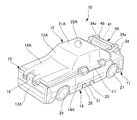
- a vehicle toy 10 is a toy imitating a sedan type vehicle, and includes a chassis 11 that constitutes the lower part of the vehicle, an upper surface member 12 that constitutes the upper surface of the vehicle, and a front member 13 that constitutes the front surface of the vehicle. And a side member 14 that constitutes the side surface of the vehicle.
- the form of the vehicle changes from the first form to the second form different from the first form by inverting the front and back of each member.
- the front member 13 has an upper end connected to the front end of the upper surface member 12 via a hinge portion 16 and is rotatable with respect to the upper surface member 12 about the hinge portion 16.
- the front member 13 may be detachable from the top member 12 at the hinge portion 16.
- the side member 14 has an upper end connected to a side end of the upper surface member 12 via a hinge portion 17 and is rotatable with respect to the upper surface member 12 around the hinge portion 17.
- the side member 14 may be detachable from the top member 12 at the hinge portion 17.
- the upper surface member 12 is connected to the chassis 11 by the connecting means 40 and is rotatable in two directions. A mechanism for rotating the upper surface member 12 in two directions will be described later. Further, the upper surface member 12 may be detachable from the chassis 11 via the connecting means 40.
- each of the upper surface member 12, the front member 13, and the side member 14 is the surface 12A, 13A, 14A which comprises each surface of a vehicle in a 1st form. Is facing outward.
- the back (after-mentioned) of each member will be located inside vehicle toy 10, and can hardly be visually recognized from the outside.
- symbol which shows each member "A” is attached to the surface which comprises a 1st form, and "B” is attached to the back surface which comprises a 2nd form, and it distinguishes.
- the surface 12A of the upper surface member 12 includes a front bonnet portion 18A and a roof portion 21A provided on the rear side of the bonnet portion 18A, and a spherical portion 22A is provided at the center of the roof portion 21A.
- the spherical portion 22A is one of the parts representing the features of the first form.
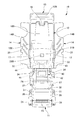
- FIG. 2 shows the vehicle toy 10 when the top member 12, the front member 13, and the side member 14 are each rotated by about 90 °, and the back side of each member is shown.
- a pair of left and right front wheels 24 are rotatably provided on the front portion of the chassis 11 via a front wheel shaft 23, and a pair of left and right front wheels 24 are disposed on the rear portion of the chassis 11 via a rear wheel shaft 26.
- a rear wheel 27 is rotatably provided.
- the left and right side ends of the chassis 11 are provided with projecting pieces 28 projecting sideways.
- the protruding piece 28 is provided with a U-shaped notch 31 that opens upward and laterally.
- a rectangular through hole 32 is provided at the center of the chassis 11.
- Each of the top member 12, the front member 13, and the side member 14 has back surfaces 12B, 13B, and 14B that constitute each surface of the vehicle in the second embodiment.
- the rear surface 12B of the upper surface member 12 includes a front bonnet portion 18B and a roof portion 21B provided on the rear side of the bonnet portion 18B.
- a prism portion 22B is provided at the center of the roof portion 21B.
- the prism portion 22B is one of the parts representing the features of the second form.
- the upper surface member 12 is supported on the upper surface of the chassis 11 in the first form and the second form.
- the back surface 12 ⁇ / b> B is supported on the top surface of the chassis 11, and the prism portion 22 ⁇ / b> B escapes to the through hole 32.
- the surface 12A (see FIG. 1) is supported on the upper surface of the chassis 11 and the spherical portion 22A (see FIG. 1) escapes to the through hole 32.
- the user contacts and pushes the prism portion 22B in the first configuration, and the spherical portion 22A in the second configuration, thereby pushing the top member 12 away from the chassis 11. It can be used as a trigger to turn the head.
- the side member 14 is provided with a fitting piece 33 corresponding to the notch 31 of the chassis 11.
- the fitting piece 33 can be fitted into the notch 31 from above or from the side because the notch 31 has a U-shape that opens upward and laterally. It plays a role of holding the form in the first form or the second form.
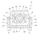
- the connecting means 40 includes a separation rotation shaft 41 supported at both ends by the left and right support portions 34, a rotation body 42 rotatably supported by the separation rotation shaft 41, and a forward direction from the rotation body 42. And a reversing rotation shaft 43 and a gear-like engaged body 44 provided on the outer periphery of the reversing rotation shaft 43.
- the rotating body 42 has a rotation restricting portion 46 extending in the left-right direction in the vicinity of the front side of the separating rotation shaft 41.
- the rotation restricting portion 46 is configured such that when the rotating body 42 is rotated by a predetermined angle, the rear surface 46 a comes into contact with the upper surface 34 a of the support portion 34, and restricts the rotation angle of the rotating body 42.
- the maximum angle at which the rotating body 42 can rotate is 90 °. This maximum angle is not particularly limited and can be arbitrarily set.
- the upper surface member 12 is divided into two in the front and back direction, and includes a front surface side divided body 47A that forms the front surface 12A and a back surface side divided body 47B that forms the back surface 12B.
- a storage portion 48 for storing the engaged body 44 and a bearing portion 51 for supporting the reversing rotation shaft 43 are provided inside the upper surface member 12, a storage portion 48 for storing the engaged body 44 and a bearing portion 51 for supporting the reversing rotation shaft 43 are provided inside the upper surface member 12, a storage portion 48 for storing the engaged body 44 and a bearing portion 51 for supporting the reversing rotation shaft 43 are provided. It is formed.
- the reversing rotation shaft 43 is inserted so as to be sandwiched between the front surface side divided body 47A and the back surface side divided body 47B, and is supported by the bearing portion 51.
- the upper surface member 12 is supported so as to be rotatable in a direction (upward) away from the chassis 11 with the separation rotation shaft 41 as a center, and in a direction in which the front and back are reversed with the reversal rotation shaft 43 as a center. Is also supported rotatably.
- the engaging bodies 52 are fixed to the left and right sides of the engaged body 44 in the storage portion 48.
- the engaging body 52 is elastically deformable and has a claw portion 52a protruding inward.
- the claw portion 52a meshes with the valley portion of the engaged body 44, and when the upper surface member 12 rotates about the reversing rotation shaft 43, the claw portion 52a escapes outward and climbs over the mountain portion of the engaged body 44. Rotate along the valleys and peaks of the engaged body 44. Thereby, the user who operates the upper surface member 12 can obtain a click feeling by operation
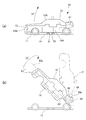
- FIG. 6A is a side view showing the vehicle toy 10 of the first embodiment.
- the user operates the side member 14 and the like to remove the fitting piece 33 from the notch 31.
- the upper surface member 12 is rotated in the direction of the arrow (1), that is, in the direction away from the chassis 10 around the separation rotation shaft 41.
- the front member 13 and the side member 14 are connected only to the upper surface member 12, the front member 13 and the side member 14 rotate together with the upper surface member 12 in a direction away from the chassis 11.
- the upper surface member is simply operated without operating the side member 14 and the like to separate the fitting piece 33 from the notch 31 in advance.
- the fitting piece 33 may be detached upward from the notch 31 as the 12 is rotated in a direction away from the chassis 11.
- the front member 13 and the side member 14 can be rotated in the direction in which the front and back are reversed around the hinge portions 16 and 17 by their own weight as the front and back are reversed. Therefore, as shown in FIG. 7A, the front member 13 and the side member 14 are hinged by the weight of the front member 13 and the side member 14 due to the weight of the front member 13 and the side member 14 without depending on the user's hand. Can be rotated in the direction indicated by the arrows (3) and (4), that is, the direction in which the front and back sides are reversed.
- the front member 13 and the side member 14 can also be rotated in the direction in which the front and back are reversed. .
- the infant who is the main user can easily change the form.
- the vehicle toy 10 which turned the back surface 12B, 13B, 14B of each member to the outer side is obtained on the chassis 11, and the change to a 2nd form is completed. Even when the vehicle toy 10 is changed from the second form to the first form, the same operation as that described above is performed.
- the front member 13 and the side member 14 are rotated with respect to the upper surface member 12 and then returned to the chassis 11. However, after the upper surface member 12 is returned to the chassis 11, the front member 13 or You may make it complete rotation of the side member 14.
- the appearance can be easily changed by simply lifting the upper surface member 12 and turning it upside down and rotating the front member 13 and the side member 14. That is, it is not necessary to individually rotate each member with respect to the chassis 11. Moreover, since the front member 13 and the side member 14 are connected to the upper member 12, a conventional support frame is not required. As a result, a structure with high strength can be obtained.
- the engaged body 44 and the engaging body 52 allow the user to obtain a click feeling when rotating the top member 12, so that the user can enjoy the feeling of the rotating operation.
- the rotation angle of the rotating body 42 can be restricted by bringing the rotation restricting portion 46 into contact with the upper surface 34a of the support portion 34. Thereby, it can prevent that the upper surface member 12 rotates more than necessary. Therefore, the operation for changing the shape is further facilitated.
- the vehicle toy 60 is a toy imitating a large vehicle, and includes a chassis 61 that constitutes the lower part of the vehicle, an upper surface member 62 that constitutes the upper surface (vehicle upper surface) of the cargo compartment, and a compartment part. It has a front member 63 that constitutes the (vehicle front) and a side member 64 that constitutes the side (vehicle side) of the cargo compartment.
- the form of the vehicle is changed from the first form to the second form by inverting the front and back of each member.
- the chassis 61 is provided with left and right front wheels 74 and two left and right rear wheels 77 rotatably.
- projecting pieces 78 projecting sideways are provided at the left and right side ends of the chassis 61.
- the protruding piece 78 is provided with a U-shaped notch 81 that opens upward and laterally.
- the upper end of the front member 63 is connected to the front end of the upper surface member 62 via the hinge portion 66, and is rotatable with respect to the upper surface member 62 around the hinge portion 66.
- the front member 63 may be detachable from the upper surface member 62 at the hinge portion 16.
- the lower end of the front member 63 is supported on the upper surface of the chassis 61.
- the side member 64 has an upper end connected to a side end of the upper surface member 62 via a hinge portion 67 and is rotatable with respect to the upper surface member 62 about the hinge portion 67.
- the side member 64 may be detachable from the upper surface member 62 at the hinge portion 67.
- the upper surface member 62 is connected to the chassis 61 by the connecting means 90 and is rotatable in two directions. A mechanism for rotating the upper surface member 62 in two directions will be described later. Further, the upper surface member 62 may be detachable from the chassis 11 via the connecting means 90.
- FIG. 8 shows a vehicle toy 60 of the first form simulating a truck, and each of the top member 62, the front member 63, and the side member 64 is a surface 62A that constitutes each surface of the vehicle in the first form. , 63A, 64A are directed outward.
- symbol which shows each member "A” is attached to the surface which comprises a 1st form, and "B” is attached to the back surface which comprises a 2nd form, and it distinguishes.
- the side member 64 is provided with a fitting piece 83 corresponding to the notch 81 of the chassis 61. Since the notch 81 has a U-shape that opens upward and laterally, the fitting piece 83 can be fitted into the notch 81 from above or from the side. It plays a role of holding the form in the first form or the second form.
- left and right support portions 84 (only the right support portion is shown in the figure) are formed on the upper rear wall of the chassis 61.
- the connecting means 90 is disposed between the left and right support portions 84.
- the connecting means 90 includes a separation rotation shaft 91 supported at both ends by the left and right support portions 84, a rotation body 92 rotatably supported by the separation rotation shaft 91, and a forward direction from the rotation body 92. And a reversing rotation shaft 93 and a gear-like engaged body 94 provided on the outer periphery of the reversing rotation shaft 93.
- the upper surface member 62 is a plate-like member that is divided into two in the front and back direction, and includes a front surface side divided body 97A that forms the front surface 62A and a back surface side divided body 97B that forms the back surface 62B.
- the rear end portions of the front surface side divided body 97A and the back surface side divided body 97B are formed in a shape protruding upward and downward with respect to the other plate-like portions, and are formed in a hollow shape.
- a housing portion 98 for housing the engaged body 94 is formed at the rear end portion of the upper surface member 62, and at the rear end of the upper surface member 62, it is reversed.
- a bearing portion 101 that supports the rotary shaft 93 is formed.
- the reversing rotation shaft 93 is inserted so as to be sandwiched between the front surface side divided body 97 ⁇ / b> A and the back surface side divided body 97 ⁇ / b> B and supported by the bearing portion 101.
- the upper surface member 62 is supported so as to be rotatable in a direction (upward) away from the chassis 61 with the separation rotation shaft 91 as a center, and in a direction to reverse the front and back with the reversal rotation shaft 93 as a center. Is also supported rotatably.
- the rear end surface 96 of the upper surface member 62 restricts the rotation of the upper surface member 62 around the separation rotation shaft 91. That is, the rear end surface 96 abuts on the front surface 84b of the support portion 84 in the first form or the second form, and prevents the upper surface member 62 from rotating downward.
- the rear end surface 96 of the upper surface member 62 comes into contact with the upper surfaces 84a of the left and right support portions 84 as shown by the two-dot chain line, and the upper surface member 62 is rotated. Stop.
- the angle formed by the rear end surface 96 and the upper surface 84a is set to 90 °, and the maximum angle at which the upper surface member 62 can rotate is 90 °. This maximum angle is not particularly limited and can be arbitrarily set.
- Engaging bodies (not shown) similar to the engaging body 52 (see FIG. 5) are fixed to the left and right sides of the engaged body 94 in the storage section 98. Thereby, the user who operates the upper surface member 62 can obtain a click feeling by the movement of the nail
- the vehicle toy 60 of the other embodiment described above it is possible to change from the first form to the second form in the same procedure as the vehicle toy 10 described above.
- the user operates the side member 64 and the like to remove the fitting piece 83 from the notch 81.
- the upper surface member 62 is rotated in the direction of the arrow (6), that is, in the direction away from the chassis 61, as shown in FIG.
- the front member 63 and the side member 64 are connected only to the upper surface member 62, the front member 63 and the side member 64 rotate together with the upper surface member 62 in a direction away from the chassis 11.
- the upper surface member is simply operated without operating the side surface member 64 and the like to separate the fitting piece 83 from the notch 81 in advance.
- the fitting piece 83 may be detached upward from the notch 81 as the 62 is rotated in the direction away from the chassis 61.
- the upper surface member 62 is centered on the axis 93a of the rotation shaft for reversal using the space formed between the members 62, 63, 64 and the chassis 61. 62 is rotated in the direction of the arrow (7), that is, the direction in which the front and back are reversed.
- the front member 63 and the side member 64 can be rotated in the direction in which the front and back are reversed around the hinge portions 66 and 67 by the slave in accordance with the front and back inversion of the upper surface member 62. For this reason, the front member 63 and the side member 64 have the arrows (8) and (8) centered on the hinge portions 66 and 67 by their own weights without depending on the user's hand as the upper and lower surfaces 62 are reversed. It is possible to rotate in the direction indicated by 9), that is, the direction in which the front and back sides are reversed.
- the front member 63 and the side member 64 can also be rotated in the direction in which the front and back are reversed. .
- the infant who is the main user can change the form.
- the upper surface member 62 is reversed and the front member 63 and the side member 64 are rotated by 180 ° with respect to the upper surface member 62, the surface of each member is hidden and hidden inside the vehicle toy 60.
- the back surfaces 62B, 63B, and 64B face outward and are exposed.
- the chassis 61 returns the members 62, 63, and 64 to the chassis 61.
- the notch 81 is open upward, it can be easily fitted if the upper surface member 62 is rotated in a direction approaching the chassis 61 with the fitting piece 83 facing downward.
- the piece 83 can be fitted into the notch 81 from above.
- the vehicle toy 60 having the shape of a fire truck is obtained on the chassis 61 with the back surfaces 62B, 63B, 64B of the respective members facing outward, and the change to the second form is completed. To do.
- the vehicle toy 60 is changed from the second form to the first form, the same operation as that described above is performed. Also in the vehicle toy 60 of the other embodiments described above, the same operational effects as those of the vehicle toy 10 of the above-described embodiment can be obtained.
- the front member is connected to the front portion of the upper surface member, and the connecting means is provided to the rear portion of the upper surface member.
- the rear member constituting the rear surface of the vehicle is connected to the rear portion of the upper surface member.
- the connecting means may be provided at the front part of the upper surface member.
- the connecting means may be variously modified in addition to the separation rotating shaft and the reversing rotating shaft.
- the connecting means may be composed of a spherical portion provided on one of the chassis or the upper surface member and a holding portion provided on the other side for rotatably holding the spherical portion. Even with such a connecting member, it is possible to support the upper surface member so as to be rotatable in a direction away from the chassis, and to rotatably support the upper surface member apart from the chassis in a direction of reversing the front and back. . Moreover, it is good also as a thin-plate part which can be bend
Landscapes
- Toys (AREA)
Abstract
【課題】 外観を容易に変化させることができ、しかも、強度の高い構造が得られる車両玩具を提供する。 【解決手段】 車両玩具10は、第1の形態から第2の形態に変化するものであって、車両下部を構成する車台11と、表面12Aが第1の形態における車両上面を構成し、裏面が第2の形態における車両上面を構成する上面部材12と、上面部材12の前部に回動可能に連結され、表面13Aが第1の形態における車両前面を構成し、裏面が第2の形態における車両前面を構成する前面部材13と、上面部材12の後部を車台11に連結する連結手段40と、を有する。連結手段40は、上面部材12を車台11から離れる方向に回動可能に支持する離間用回動軸41と、車台11から離れた上面部材12を表裏反転させる方向に回動可能に支持する反転用回動軸と、を有する。
Description
本発明は、車両玩具に関し、より詳細には、第1の形態の車両から、第1の形態とは異なる第2の形態の車両に変化する車両玩具に関する。
従来の車両玩具として、表裏に異なる外観を施した複数の部材を有し、操作者が各部材を回動させて各部材の表裏を逆にし、異なる外観の車両玩具に変化させるものが知られている(たとえば、特許文献1参照)。
特許文献1記載の車両玩具では、支持枠にボディ側壁とボディ前面とボディ後面を上下に回動可能に取り付ける。操作者は、ボディ側壁とボディ前面とボディ後面を上方に回動させることで、車両玩具の外観を変化させることができる。
しかしながら、特許文献1に記載された車両玩具において、車両の外観を変化させるには、ボディ側壁、ボディ前面、ボディ後面をそれぞれ個別に回動操作する必要がある。玩具の主たる使用者である幼児には、操作が複雑であるため、車両の外観を変化させることが難しいという問題点があった。
また、玩具の外観を大幅に変化させるためには、ボディ側壁やボディ前面等をできるだけ大きく形成することが好ましい。しかし、特許文献1に記載される玩具の構造では、ボディ側壁やボディ前面等が支持枠に取り付けられるため、ボディ側壁やボディ前面等を大きく形成すると、支持枠が必然的に細くなってしまう。支持枠が細くなると、幼児が使用する玩具に求められる強度を確保できなくなる。
そこで、本発明は、外観を容易に変化させることができ、しかも、高い強度が得られる車両玩具を提供することにある。
本発明は、以下に示す構成によって把握される。
(1)本発明の車両玩具は、第1の形態と第2の形態とに変化する車両玩具であって、車両下部を構成する車台と、前記車台の上方に設けられ、表面が前記第1の形態における車両上面を構成する一方、裏面が前記第2の形態における車両上面を構成する上面部材と、前記上面部材の前部に回動可能に連結され、表面が前記第1の形態における車両前面を構成する一方、裏面が前記第2の形態における車両前面を構成する前面部材と、前記上面部材の後部を前記車台に連結する連結手段と、を有し、前記連結手段は、前記上面部材を前記車台から離れる方向に回動可能に支持する離間用回動軸と、前記上面部材を表裏反転させる方向に回動可能に支持する反転用回動軸と、を有することを特徴とする。
(1)本発明の車両玩具は、第1の形態と第2の形態とに変化する車両玩具であって、車両下部を構成する車台と、前記車台の上方に設けられ、表面が前記第1の形態における車両上面を構成する一方、裏面が前記第2の形態における車両上面を構成する上面部材と、前記上面部材の前部に回動可能に連結され、表面が前記第1の形態における車両前面を構成する一方、裏面が前記第2の形態における車両前面を構成する前面部材と、前記上面部材の後部を前記車台に連結する連結手段と、を有し、前記連結手段は、前記上面部材を前記車台から離れる方向に回動可能に支持する離間用回動軸と、前記上面部材を表裏反転させる方向に回動可能に支持する反転用回動軸と、を有することを特徴とする。
(2)本発明の車両玩具は、第1の形態と第2の形態とに変化する車両玩具であって、車両下部を構成する車台と、前記車台の上方に設けられ、表面が前記第1の形態における車両上面を構成する一方、裏面が前記第2の形態における車両上面を構成する上面部材と、前記上面部材の後部に回動可能に連結され、表面が前記第1の形態における車両後面を構成する一方、裏面が前記第2の形態における車両後面を構成する後面部材と、前記上面部材の前部を前記車台に連結する連結手段と、を有し、前記連結手段は、前記上面部材を前記車台から離れる方向に回動可能に支持する離間用回動軸と、前記上面部材を表裏反転させる方向に回動可能に支持する反転用回動軸と、を有することを特徴とする。
(3)本発明の車両玩具は、(1)または(2)の構成において、前記上面部材の側部に回動可能に連結され、表面が前記第1の形態における車両側面を構成する一方、裏面が前記第2の形態における車両側面を構成する側面部材を有することを特徴とする。
(4)本発明の車両玩具は、第1の形態と第2の形態とに変化する車両玩具であって、車両下部を構成する車台と、前記車台の上方に設けられ、表面が前記第1の形態における車両上面を構成する一方、裏面が前記第2の形態における車両上面を構成する上面部材と、前記上面部材の側部に回動可能に連結され、表面が前記第1の形態における車両側面を構成する一方、裏面が前記第2の形態における車両側面を構成する側面部材と、前記上面部材を前記車台に連結する連結手段と、を有し、前記連結手段は、前記上面部材を前記車台から離れる方向に回動可能に支持する離間用回動軸と、前記上面部材を表裏反転させる方向に回動可能に支持する反転用回動軸と、を有することを特徴とする。
(5)本発明の車両玩具は、第1の形態と第2の形態とに変化する車両玩具であって、車両下部を構成する車台と、前記車台の上方に設けられ、表面が前記第1の形態における車両上面を構成する一方、裏面が前記第2の形態における車両上面を構成する上面部材と、前記上面部材を前記車台に連結する連結手段と、を有し、前記連結手段は、前記上面部材を前記車台から離れる方向に回動可能に支持する離間用回動軸と、前記上面部材を表裏反転させる方向に回動可能に支持する反転用回動軸と、を有することを特徴とする。
(6)本発明の車両玩具は、(1)~(5)のいずれかの構成において、前記反転用回動軸の外周に設けられる歯車状の被係合体と、前記被係合体の谷部に係合し、前記上面部材が前記反転用回動軸を中心に回動するとき、前記被係合体の山部を乗り越えながら前記谷部と前記山部に沿って回動する爪部と、を有することを特徴とする。
(7)本発明の車両玩具は、第1の形態と第2の形態とに変化する車両玩具であって、車両下部を構成する車台と、前記車台の上方に設けられ、表面が前記第1の形態における車両上面を構成する一方、裏面が前記第2の形態における車両上面を構成する上面部材と、前記上面部材の前部に回動可能に連結され、表面が前記第1の形態における車両前面を構成する一方、裏面が前記第2の形態における車両前面を構成する前面部材と、前記上面部材の後部を前記車台に連結する連結手段と、を有し、前記連結手段は、前記上面部材と前記車台のいずれか一方に設けられた球状部と、他方に設けられ前記球状部を回動可能に抱持する抱持部とからなり、前記上面部材を前記車台から離れる方向に回動可能に支持し、かつ、前記上面部材を表裏反転させる方向に回動可能に支持することを特徴とする。
(8)本発明の車両玩具は、第1の形態と第2の形態とに変化する車両玩具であって、車両下部を構成する車台と、前記車台の上方に設けられ、表面が前記第1の形態における車両上面を構成する一方、裏面が前記第2の形態における車両上面を構成する上面部材と、前記上面部材の後部に回動可能に連結され、表面が前記第1の形態における車両後面を構成する一方、裏面が前記第2の形態における車両後面を構成する後面部材と、前記上面部材の前部を前記車台に連結する連結手段と、を有し、前記連結手段は、前記上面部材と前記車台のいずれか一方に設けられた球状部と、他方に設けられ前記球状部を回動可能に抱持する抱持部とからなり、前記上面部材を前記車台から離れる方向に回動可能に支持し、かつ、前記上面部材を表裏反転させる方向に回動可能に支持することを特徴とする。
(9)本発明の車両玩具は、(7)または(8)の構成において、前記上面部材の側部に回動可能に連結され、表面が前記第1の形態における車両側面を構成する一方、裏面が前記第2の形態における車両側面を構成する側面部材を有することを特徴とする。
(10)本発明の車両玩具は、第1の形態と第2の形態とに変化する車両玩具であって、車両下部を構成する車台と、前記車台の上方に設けられ、表面が前記第1の形態における車両上面を構成する一方、裏面が前記第2の形態における車両上面を構成する上面部材と、前記上面部材の側部に回動可能に連結され、表面が前記第1の形態における車両側面を構成する一方、裏面が前記第2の形態における車両側面を構成する側面部材と、前記上面部材を前記車台に連結する連結手段と、を有し、前記連結手段は、前記上面部材と前記車台のいずれか一方に設けられた球状部と、他方に設けられ前記球状部を回動可能に抱持する抱持部とからなり、前記上面部材を前記車台から離れる方向に回動可能に支持し、かつ、前記上面部材を表裏反転させる方向に回動可能に支持することを特徴とする。
(11)本発明の車両玩具は、第1の形態と第2の形態とに変化する車両玩具であって、車両下部を構成する車台と、前記車台の上方に設けられ、表面が前記第1の形態における車両上面を構成する一方、裏面が前記第2の形態における車両上面を構成する上面部材と、前記上面部材を前記車台に連結する連結手段と、を有し、前記連結手段は、前記上面部材と前記車台のいずれか一方に設けられた球状部と、他方に設けられ前記球状部を回動可能に抱持する抱持部とからなり、前記上面部材を前記車台から離れる方向に回動可能に支持し、かつ、前記車台から離れた前記上面部材を表裏反転させる方向に回動可能に支持することを特徴とする。
(12)本発明の車両玩具は、第1の形態と第2の形態とに変化する車両玩具であって、車両下部を構成する車台と、前記車台の上方に設けられ、表面が前記第1の形態における車両上面を構成する一方、裏面が前記第2の形態における車両上面を構成する上面部材と、前記上面部材の前部に回動可能に連結され、表面が前記第1の形態における車両前面を構成する一方、裏面が前記第2の形態における車両前面を構成する前面部材と、前記上面部材の後部を前記車台に連結する連結手段と、を有し、前記連結手段は、前記上面部材を前記車台から離れる方向に回動可能に支持する折り曲げ可能な薄板部と、前記上面部材を表裏反転させる方向に回動可能に支持する反転用回動軸と、を有することを特徴とする。
(13)本発明の車両玩具は、第1の形態と第2の形態とに変化する車両玩具であって、車両下部を構成する車台と、前記車台の上方に設けられ、表面が前記第1の形態における車両上面を構成する一方、裏面が前記第2の形態における車両上面を構成する上面部材と、前記上面部材の後部に回動可能に連結され、表面が前記第1の形態における車両後面を構成する一方、裏面が前記第2の形態における車両後面を構成する後面部材と、前記上面部材の前部を前記車台に連結する連結手段と、を有し、前記連結手段は、前記上面部材を前記車台から離れる方向に回動可能に支持する折り曲げ可能な薄板部と、前記上面部材を表裏反転させる方向に回動可能に支持する反転用回動軸と、を有することを特徴とする。
(14)本発明の車両玩具は、(12)または(13)の構成において、前記上面部材の側部に回動可能に連結され、表面が前記第1の形態における車両側面を構成する一方、裏面が前記第2の形態における車両側面を構成する側面部材を有することを特徴とする。
(15)本発明の車両玩具は、第1の形態と第2の形態とに変化する車両玩具であって、車両下部を構成する車台と、前記車台の上方に設けられ、表面が前記第1の形態における車両上面を構成する一方、裏面が前記第2の形態における車両上面を構成する上面部材と、前記上面部材の側部に回動可能に連結され、表面が前記第1の形態における車両側面を構成する一方、裏面が前記第2の形態における車両側面を構成する側面部材と、前記上面部材を前記車台に連結する連結手段と、を有し、前記連結手段は、前記上面部材を前記車台から離れる方向に回動可能に支持する折り曲げ可能な薄板部と、前記上面部材を表裏反転させる方向に回動可能に支持する反転用回動軸と、を有することを特徴とする。
(16)本発明の車両玩具は、第1の形態と第2の形態とに変化する車両玩具であって、車両下部を構成する車台と、前記車台の上方に設けられ、表面が前記第1の形態における車両上面を構成する一方、裏面が前記第2の形態における車両上面を構成する上面部材と、前記上面部材を前記車台に連結する連結手段と、を有し、前記連結手段は、前記上面部材を前記車台から離れる方向に回動可能に支持する折り曲げ可能な薄板部と、前記車台から離れた前記上面部材を表裏反転させる方向に回動可能に支持する反転用回動軸と、を有する。
(17)本発明の車両玩具は、(12)乃至(16)のいずれかの構成において、前記反転用回動軸の外周に設けられる歯車状の被係合体と、前記被係合体の谷部に係合し、前記上面部材が前記反転用回動軸を中心に回動するとき、前記被係合体の山部を乗り越えながら前記谷部と前記山部に沿って回動する爪部と、を有することを特徴とする。
(18)本発明の車両玩具は、(1)、(7)、(12)のいずれかの構成において、前記前面部材は、前記上面部材の表裏反転に伴って、自重によって表裏が反転する方向に回動可能であることを特徴とする。
(19)本発明の車両玩具は、(2)、(8)、(13)のいずれかの構成において、前記後面部材は、前記上面部材の表裏反転に伴って、自重によって表裏が反転する方向に回動可能であることを特徴とする。
(20)本発明の車両玩具は、(3)、(4)、(9)、(10)、(14)、(15)のいずれかの構成において、前記側面部材は、前記上面部材の表裏反転に伴って、自重によって表裏が反転する方向に回動可能であることを特徴とする。
(21)本発明の車両玩具は、(1)乃至(20)のいずれかの構成において、前記上面部材の表面には第1の形態の特徴を表す部位が設けられており、前記車台には、第2の形態において前記第1の形態の特徴を表す部位が逃げることが可能な貫通穴が設けられている。
本発明の車両玩具によれば、外観を容易に変化させることができ、かつ、強度の高い構造を得ることができる。
以下、添付図面を参照して、本発明を実施するための形態(以下、実施形態)について詳細に説明する。なお、実施形態の説明の全体を通して同じ要素には同じ番号を付している。
図1に示すように、車両玩具10は、セダン型車両を模した玩具であって、車両下部を構成する車台11と、車両上面を構成する上面部材12と、車両前面を構成する前面部材13と、車両側面を構成する側面部材14と、を有する。車両玩具10では、各部材の表裏を反転させることで、車両の形態が第1の形態から、第1の形態とは異なる第2の形態に変化する。
前面部材13は、上端がヒンジ部16を介して上面部材12の前端に連結されており、ヒンジ部16を中心に上面部材12に対して回動可能である。なお、前面部材13は、上面部材12に対してヒンジ部16において着脱可能としても良い。側面部材14は、上端がヒンジ部17を介して上面部材12の側端に連結されており、ヒンジ部17を中心に上面部材12に対して回動可能である。なお、側面部材14は、上面部材12に対してヒンジ部17において着脱可能としても良い。上面部材12は、連結手段40によって車台11に連結され、2方向に回動可能である。なお、上面部材12を2方向に回動させるための機構については後述する。また、上面部材12は、車台11に対して連結手段40を介して着脱可能としても良い。
図1では、車両玩具10の第1の形態を示しており、上面部材12、前面部材13、側面部材14のそれぞれは、第1の形態において車両の各面を構成する表面12A,13A,14Aを外側に向けている。第1の形態では、各部材の裏面(後述)は、車両玩具10の内側に位置することになり、外からほとんど視認できない。なお、各部材を示す符号において、第1の形態を構成する表面には「A」を付け、第2の形態を構成する裏面には「B」を付けて、区別する。
上面部材12の表面12Aは、前部のボンネット部18Aと、ボンネット部18Aの後側に設けられるルーフ部21Aと、を備えており、ルーフ部21Aの中央には、球状部22Aが設けられる。球状部22Aは、第1の形態の特徴を表す部位の1つである。
図2では、上面部材12、前面部材13、側面部材14をそれぞれ90°程度回動させたときの車両玩具10を示しており、各部材の裏側を示している。図2に示すように、車台11の前部には、前輪軸23を介して左右1対の前輪24が回転自在に設けられ、車台11の後部には、後輪軸26を介して左右1対の後輪27が回転自在に設けられる。また、車台11の左右の側端には、側方に突出する突出片28が設けられる。突出片28には、上方および側方に開放するコの字状の切り欠き31が設けられる。また、車台11の中央部には、長方形の貫通穴32が設けられる。
上面部材12、前面部材13、側面部材14のそれぞれは、第2の形態において車両の各面を構成する裏面12B,13B,14Bを有する。上面部材12の裏面12Bは、前部のボンネット部18Bと、ボンネット部18Bの後側に設けられるルーフ部21Bと、を備える。ルーフ部21Bの中央には、角柱部22Bが設けられる。角柱部22Bは、第2の形態の特徴を表す部位の1つである。
また、上面部材12は、第1の形態および第2の形態において、車台11の上面に支持される。第1の形態では、裏面12Bが車台11の上面に支持されると共に、角柱部22Bが貫通穴32に逃げる。一方、第2の形態では、表面12A(図1参照)が車台11の上面に支持されると共に、球状部22A(図1参照)が貫通穴32に逃げる。また、貫通穴32を通じて、使用者は第1の形態のときは角柱部22Bに、第2の形態のときは球状部22Aに接触して押すことにより、上面部材12を車台11から離間させる方向へと回動させるきっかけとすることができる。
側面部材14は、車台11の切り欠き31に対応する嵌合片33が設けられる。嵌合片33は、切り欠き31が上方および側方に開放するコの字状をしていることにより、切り欠き31に対して上方からでも側方からでも嵌入可能であり、車両玩具10の形態を第1の形態あるいは第2の形態に保持する役割を果たす。
次に、連結手段40およびその周辺構造を図3~図5に基づいて説明する。
図3に示すように、車台11の後上部には、左右1対の支持部34が形成される。連結手段40は、左右の支持部34の間に配置される。連結手段40は、左右の支持部34に両端が支持される離間用回動軸41と、離間用回動軸41に回動可能に支持される回動体42と、回動体42から前方に向けて延びる反転用回動軸43と、反転用回動軸43の外周に設けられる歯車状の被係合体44と、を有する。
図3に示すように、車台11の後上部には、左右1対の支持部34が形成される。連結手段40は、左右の支持部34の間に配置される。連結手段40は、左右の支持部34に両端が支持される離間用回動軸41と、離間用回動軸41に回動可能に支持される回動体42と、回動体42から前方に向けて延びる反転用回動軸43と、反転用回動軸43の外周に設けられる歯車状の被係合体44と、を有する。
図4に示すように、回動体42は、離間用回動軸41の前側近傍にて左右方向に延びる回動規制部46を有する。回動規制部46は、回動体42が所定角度回動すると、後面46aが支持部34の上面34aに当接するように構成されており、回動体42の回動角度を規制する。ここでは、後面46aと上面34aとがなす角度を90°に設定することで、回動体42が回動できる最大角度を90°としている。この最大角度は、格別に限定されるものではなく、任意に設定可能である。
上面部材12は、表裏方向に2分割されるものであり、表面12Aを形成する表面側分割体47Aと、裏面12Bを形成する裏面側分割体47Bとからなる。表面側分割体47Aと裏面側分割体47Bが合わさることで、上面部材12の内部には、被係合体44を収納する収納部48と、反転用回動軸43を支持する軸受け部51とが形成される。
反転用回動軸43は、表面側分割体47Aと裏面側分割体47Bに挟まれるように挿入されて、軸受け部51に支持される。これにより、上面部材12は、離間用回動軸41を中心に車台11から離れる方向(上方)に回動可能に支持されると共に、反転用回動軸43を中心に表裏が反転する方向にも回動可能に支持されていることになる。
図5に示すように、収納部48における被係合体44の左右両側には、係合体52が固定される。係合体52は、弾性変形可能であり、内向きに突出する爪部52aを有する。爪部52aは、被係合体44の谷部に噛み合っており、上面部材12が反転用回動軸43を中心に回動するとき、外向きに逃げて被係合体44の山部を乗り越えながら、被係合体44の谷部と山部に沿って回動する。これにより、上面部材12を操作する使用者は、爪部52aの動作によってクリック感を得ることができる。
次に、実施形態の車両玩具10を第1の形態から第2の形態に変化させる手順を図6、図7に基づいて説明する。
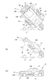
図6(a)は、第1の形態の車両玩具10を示す側面図であり、使用者は、まず、側面部材14等を操作して、切り欠き31から嵌合片33を離脱させる。そして、離間用回動軸41を中心に上面部材12を矢印(1)の向き、すなわち、車台10から離れる方向に回動させる。このとき、前面部材13と側面部材14は、上面部材12のみに連結されているため、上面部材12と一体となって車台11から離れる方向に回動する。なお、このとき、切り欠き31が上方へ開放した形状であることを利用して、あらかじめ側面部材14等を操作して切り欠き31から嵌合片33を離脱させておくことなく、単に上面部材12を車台11から離れる方向に回動させることに伴って、嵌合片33が切り欠き31から上方へと離脱するようにしても良い。
図6(a)は、第1の形態の車両玩具10を示す側面図であり、使用者は、まず、側面部材14等を操作して、切り欠き31から嵌合片33を離脱させる。そして、離間用回動軸41を中心に上面部材12を矢印(1)の向き、すなわち、車台10から離れる方向に回動させる。このとき、前面部材13と側面部材14は、上面部材12のみに連結されているため、上面部材12と一体となって車台11から離れる方向に回動する。なお、このとき、切り欠き31が上方へ開放した形状であることを利用して、あらかじめ側面部材14等を操作して切り欠き31から嵌合片33を離脱させておくことなく、単に上面部材12を車台11から離れる方向に回動させることに伴って、嵌合片33が切り欠き31から上方へと離脱するようにしても良い。
図6(b)に示すように、上面部材12を十分に回動させると、各部材12,13,14と車台11との間に空間が形成される。この空間を利用して、次は反転用回動軸43の軸線43aを中心に、上面部材12を矢印(2)の向き、すなわち、表裏が反転する方向に回動させる。
前面部材13,側面部材14は、上面部材12の表裏反転に伴って、自重によってヒンジ部16,17を中心に表裏が反転する方向に回動することができる。そのため、図7(a)に示すように、前面部材13,側面部材14は、上面部材12の表裏反転に伴って、使用者の手に拠らずとも、その自重によって、ヒンジ部16,17を中心に矢印(3),(4)で示す向き、すなわち、表裏が反転する方向に回動することが可能である。すなわち、上面部材12を車台11から離れる方向に回動させて表裏が反転する方向に回動させることで、ほぼ同時に、前面部材13,側面部材14も表裏反転する方向に回動させることができる。このことにより、主たる使用者である幼児でも容易に形態を変化させることができるようになっている。
このように、上面部材12を反転させ、かつ、前面部材13、側面部材14のそれぞれを上面部材12に対して180°回動させると、図7(b)に示すように、各部材の表面が車両玩具10の内側に隠れる一方、隠れていた裏面12B,13B,14Bが外側に向き、露出する。そして、離間用回動軸41を中心に、上面部材12を矢印(5)で示す向き、すなわち、車台11に近づく方向に回動させると、上面部材12、前面部材13、側面部材14は車台11に戻る。このとき、切り欠き31が上方に開放した形状をしているため、図7(b)に示すように、嵌合片33が下方に向いた状態で上面部材12を車台11に近づく方向へと回動させれば、容易に嵌合片33を切り欠き31に上から嵌入させることができる。
すると、図7(c)に示すように、車台11上において、各部材の裏面12B,13B,14Bを外側に向けた車両玩具10が得られ、第2の形態への変化が完了する。この第2の形態から車両玩具10を第1の形態に変化させる際も、上述した手順と同じ操作を行う。
なお、この例では、前面部材13と側面部材14を上面部材12に対して回動させた後、車台11に戻すようにしたが、上面部材12を車台11に戻した後、前面部材13あるいは側面部材14の回動を完了させるようにしてもよい。切り欠き31は側方にも開放した形状をしているため、その場合は、嵌合片33を切り欠き31に側方から嵌入させれば良い。
以上、説明した実施形態の車両玩具によれば、上面部材12を持ち上げて表裏反転させ、前面部材13と側面部材14を回動させるだけの操作で、外観を容易に変化させることができる。すなわち、各部材を車台11に対して個別に回動させる必要がない。また、前面部材13と側面部材14を上面部材12に連結したので、従来の支持枠が不要になる。結果、強度の高い構造を得ることができる。
また、被係合体44と係合体52によって、使用者は、上面部材12を回動する際、クリック感を得ることができるので、回動操作の感触を楽しむことができる。
さらに、図6(b)において二点鎖線で示すように、回動規制部46を支持部34の上面34aに当接させることで、回動体42の回動角度を規制できる。これにより、必要以上に上面部材12が回動することを防止できる。したがって、形態変化の操作がさらに容易になる。
次に、他の実施形態の車両玩具を図8~図11に基づいて説明する。
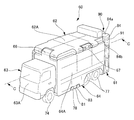
図8に示すように、車両玩具60は、大型車両を模した玩具であって、車両下部を構成する車台61と、荷室の上面(車両上面)を構成する上面部材62と、車室部(車両前面)を構成する前面部材63と、荷室の側面(車両側面)を構成する側面部材64と、を有する。車両玩具60では、前述した車両玩具10と同様に、各部材の表裏を反転させることで、車両の形態が第1の形態から第2の形態に変化する。
図8に示すように、車両玩具60は、大型車両を模した玩具であって、車両下部を構成する車台61と、荷室の上面(車両上面)を構成する上面部材62と、車室部(車両前面)を構成する前面部材63と、荷室の側面(車両側面)を構成する側面部材64と、を有する。車両玩具60では、前述した車両玩具10と同様に、各部材の表裏を反転させることで、車両の形態が第1の形態から第2の形態に変化する。
車台61には、左右の前輪74および左右2組の後輪77が回転自在に設けられる。また、車台61の左右の側端には、側方に突出する突出片78が設けられる。突出片78には、上方および側方に開放するコの字状の切り欠き81が設けられる。
前面部材63は、上端がヒンジ部66を介して上面部材62の前端に連結されており、ヒンジ部66を中心に上面部材62に対して回動可能である。なお、前面部材63は、上面部材62に対してヒンジ部16において着脱可能としても良い。前面部材63の下端は、車台61の上面に支持される。側面部材64は、上端がヒンジ部67を介して上面部材62の側端に連結されており、ヒンジ部67を中心に上面部材62に対して回動可能である。なお、側面部材64は、上面部材62に対してヒンジ部67において着脱可能としても良い。上面部材62は、連結手段90によって車台61に連結され、2方向に回動可能である。なお、上面部材62を2方向に回動させるための機構については後述する。また、上面部材62は、車台11に対して連結手段90を介して着脱可能としても良い。
図8では、トラックを模した第1の形態の車両玩具60を示しており、上面部材62、前面部材63、側面部材64のそれぞれは、第1の形態において車両の各面を構成する表面62A,63A,64Aを外側に向けている。第1の形態では、各部材の裏面は車両玩具60の内側に位置するため、外部からほとんど視認できない。なお、各部材を示す符号において、第1の形態を構成する表面には「A」を付け、第2の形態を構成する裏面には「B」を付けて、区別する。
側面部材64は、車台61の切り欠き81に対応する嵌合片83が設けられる。嵌合片83は、切り欠き81が上方および側方に開放するコの字形状をしていることにより、切り欠き81に対して上方からでも側方からでも嵌入可能であり、車両玩具60の形態を第1の形態あるいは第2の形態に保持する役割を果たす。
次に、連結手段90およびその周辺構造を図9に基づいて説明する。
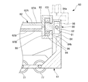
図9に示すように、車台61の後壁上部には、左右の支持部84(図では右側の支持部のみを示す)が形成される。連結手段90は、左右の支持部84の間に配置される。連結手段90は、左右の支持部84に両端が支持される離間用回動軸91と、離間用回動軸91に回動可能に支持される回動体92と、回動体92から前方に向けて延びる反転用回動軸93と、反転用回動軸93の外周に設けられる歯車状の被係合体94と、を有する。
図9に示すように、車台61の後壁上部には、左右の支持部84(図では右側の支持部のみを示す)が形成される。連結手段90は、左右の支持部84の間に配置される。連結手段90は、左右の支持部84に両端が支持される離間用回動軸91と、離間用回動軸91に回動可能に支持される回動体92と、回動体92から前方に向けて延びる反転用回動軸93と、反転用回動軸93の外周に設けられる歯車状の被係合体94と、を有する。
上面部材62は、表裏方向に2分割される板状のものであり、表面62Aを形成する表面側分割体97Aと、裏面62Bを形成する裏面側分割体97Bとからなる。表面側分割体97Aおよび裏面側分割体97Bのそれぞれの後端部は、他の板状の部分に対して上方および下方に突出した形状に形成されており、中空に形成される。表面側分割体97Aと裏面側分割体97Bが合わさることで、上面部材62の後端部には、被係合体94を収納する収納部98が形成され、上面部材62の後端には、反転用回動軸93を支持する軸受け部101が形成される。
反転用回動軸93は、表面側分割体97Aと裏面側分割体97Bに挟まれるように挿入されて、軸受け部101に支持される。これにより、上面部材62は、離間用回動軸91を中心に車台61から離れる方向(上方)に回動可能に支持されると共に、反転用回動軸93を中心に表裏を反転させる方向にも回動可能に支持されていることになる。
上面部材62の後端面96は、離間用回動軸91を中心とする上面部材62の回動を規制する。すなわち、後端面96は、第1の形態あるいは第2の形態においては、支持部84の前面84bに当接し、上面部材62の下方への回動を阻止する。一方、上面部材62が上方に所定角度回動すると、上面部材62の後端面96は、二点鎖線で示すように、左右の支持部84の上面84aに当接し、上面部材62の回動を阻止する。ここでは、後端面96と上面84aとがなす角度を90°に設定し、上面部材62が回動できる最大角度を90°としている。この最大角度は、格別に限定されるものではなく、任意に設定可能である。
収納部98における被係合体94の左右両側には、係合体52(図5参照)と同様の係合体(図示省略)が固定される。これにより、前述した車両玩具10と同様に、上面部材62を操作する使用者は、係合体の爪部の動きにより、クリック感を得ることができる。
以上に述べた他の実施形態の車両玩具60においても、前述した車両玩具10と同様の手順で、第1の形態から第2の形態に変化させることができる。
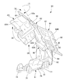
使用者は、まず側面部材64等を操作して、切り欠き81から嵌合片83を離脱させる。そして、離間用回動軸91を中心に、図10に示すように、上面部材62を矢印(6)の向き、すなわち、車台61から離れる方向に回動させる。このとき、前面部材63と側面部材64は、上面部材62のみに連結されているため、上面部材62と一体となって車台11から離れる方向に回動する。なお、このとき、切り欠き81が上方へ開放した形状であることを利用して、あらかじめ側面部材64等を操作して切り欠き81から嵌合片83を離脱させておくことなく、単に上面部材62を車台61から離れる方向に回動させることに伴って、嵌合片83が切り欠き81から上方へと離脱するようにしても良い。
使用者は、まず側面部材64等を操作して、切り欠き81から嵌合片83を離脱させる。そして、離間用回動軸91を中心に、図10に示すように、上面部材62を矢印(6)の向き、すなわち、車台61から離れる方向に回動させる。このとき、前面部材63と側面部材64は、上面部材62のみに連結されているため、上面部材62と一体となって車台11から離れる方向に回動する。なお、このとき、切り欠き81が上方へ開放した形状であることを利用して、あらかじめ側面部材64等を操作して切り欠き81から嵌合片83を離脱させておくことなく、単に上面部材62を車台61から離れる方向に回動させることに伴って、嵌合片83が切り欠き81から上方へと離脱するようにしても良い。
そして、上面部材62を十分に回動させることにより、各部材62、63、64と車台61の間に形成される空間を利用して、反転用回動軸の軸線93aを中心に、上面部材62を矢印(7)の向き、すなわち、表裏が反転する方向に回動させる。
前面部材63、側面部材64は、上面部材62の表裏反転に伴って、侍従によってヒンジ部66、67を中心に表裏が反転する方向に回動することができる。そのため、前面部材63、側面部材64は、上面部材62の表裏反転に伴って、使用者の手に拠らずとも、その自重によって、ヒンジ部66,67を中心に、矢印(8),(9)で示す向き、すなわち、表裏が反転する方向に回動することが可能である。したがって、上面部材62を車台61から離れる方向に回動させて表裏が反転する方向に回動させることで、ほぼ同時に、前面部材63、側面部材64も表裏反転する方向に回動させることができる。このことにより、主たる使用者である幼児でも形態を変化させることができるようになっている。
このように、上面部材62を反転させ、かつ、前面部材63、側面部材64を上面部材62に対して180°回動させると、各部材の表面が車両玩具60の内側に隠れ、隠れていた裏面62B,63B,64Bが外側に向き、露出する。そして、離間用回動軸91(図9参照)を中心に上面部材62を車台11に近つく方向に回動させると、各部材62,63,64を車台61は車台61に戻る。このとき、切り欠き81が上方に開放した形状をしているため、嵌合片83が下方に向いた状態で上面部材62を車台61に近づく方向へと回動させれば、容易に嵌合片83を切り欠き81に上から嵌入させることができる。
すると、図11に示すように、車台61上において、各部材の裏面62B,63B,64Bを外側に向け、消防車の形状を呈する車両玩具60が得られ、第2の形態への変化が完了する。この第2の形態から車両玩具60を第1の形態に変化させる際も、上述した手順と同じ操作を行う。以上に述べた他の実施形態の車両玩具60においても、前述した実施形態の車両玩具10と同様の作用効果を得ることができる。
以上、実施形態を用いて本発明を説明したが、本発明の技術的範囲は上記実施形態に記載の範囲には限定されないことは言うまでもない。上記実施形態に、多様な変更または改良を加えることが可能であることが当業者に明らかである。またその様な変更または改良を加えた形態も本発明の技術的範囲に含まれ得ることが、特許請求の範囲の記載から明らかである。
たとえば、前述した各実施形態においては、上面部材の前部に前面部材を連結し、上面部材の後部に連結手段を設けたが、上面部材の後部に、車両後面を構成する後面部材を連結し、上面部材の前部に連結手段を設けてもよい。
また、連結手段については、離間用回動軸と反転用回動軸からなるもの以外にも様々な変形が考えられる。例えば、連結手段を、車台または上面部材の一方に設けられた球状部と、他方に設けられ当該球状部を回動可能に抱持する抱持部からなるものとしても良い。このような連結部材であっても、上面部材を車台から離れる方向に回動可能に支持し、かつ、車台から離れた上面部材を表裏反転させる方向に回動可能に支持することが可能である。また、離間用回動軸に代えて、折り曲げ可能な薄板部としても良い。このような薄板部であっても上面部材を車台から離れる方向に回動可能に支持することは可能である。
10,60 車両玩具
11,61 車台
12,62 上面部材
12A,62A 表面
12B,62B 裏面
13,63 前面部材
13A、63A 表面
13A,63B 裏面
14,64 側面部材
14A,64A 表面
14B,64B 裏面
40,90 連結手段
41,91 離間用回動軸
43,93 反転用回動軸
44,94 被係合体
52a 爪部
11,61 車台
12,62 上面部材
12A,62A 表面
12B,62B 裏面
13,63 前面部材
13A、63A 表面
13A,63B 裏面
14,64 側面部材
14A,64A 表面
14B,64B 裏面
40,90 連結手段
41,91 離間用回動軸
43,93 反転用回動軸
44,94 被係合体
52a 爪部
Claims (21)
- 第1の形態と第2の形態とに変化する車両玩具であって、
車両下部を構成する車台と、
前記車台の上方に設けられ、表面が前記第1の形態における車両上面を構成する一方、裏面が前記第2の形態における車両上面を構成する上面部材と、
前記上面部材の前部に回動可能に連結され、表面が前記第1の形態における車両前面を構成する一方、裏面が前記第2の形態における車両前面を構成する前面部材と、
前記上面部材の後部を前記車台に連結する連結手段と、を有し、
前記連結手段は、前記上面部材を前記車台から離れる方向に回動可能に支持する離間用回動軸と、前記上面部材を表裏反転させる方向に回動可能に支持する反転用回動軸と、を有することを特徴とする車両玩具。 - 第1の形態と第2の形態とに変化する車両玩具であって、
車両下部を構成する車台と、
前記車台の上方に設けられ、表面が前記第1の形態における車両上面を構成する一方、裏面が前記第2の形態における車両上面を構成する上面部材と、
前記上面部材の後部に回動可能に連結され、表面が前記第1の形態における車両後面を構成する一方、裏面が前記第2の形態における車両後面を構成する後面部材と、
前記上面部材の前部を前記車台に連結する連結手段と、を有し、
前記連結手段は、前記上面部材を前記車台から離れる方向に回動可能に支持する離間用回動軸と、前記上面部材を表裏反転させる方向に回動可能に支持する反転用回動軸と、を有することを特徴とする車両玩具。 - 前記上面部材の側部に回動可能に連結され、表面が前記第1の形態における車両側面を構成する一方、裏面が前記第2の形態における車両側面を構成する側面部材を有することを特徴とする請求項1または2に記載の車両玩具。
- 第1の形態と第2の形態とに変化する車両玩具であって、
車両下部を構成する車台と、
前記車台の上方に設けられ、表面が前記第1の形態における車両上面を構成する一方、裏面が前記第2の形態における車両上面を構成する上面部材と、
前記上面部材の側部に回動可能に連結され、表面が前記第1の形態における車両側面を構成する一方、裏面が前記第2の形態における車両側面を構成する側面部材と、
前記上面部材を前記車台に連結する連結手段と、を有し、
前記連結手段は、前記上面部材を前記車台から離れる方向に回動可能に支持する離間用回動軸と、前記上面部材を表裏反転させる方向に回動可能に支持する反転用回動軸と、を有することを特徴とする車両玩具。 - 第1の形態と第2の形態とに変化する車両玩具であって、
車両下部を構成する車台と、
前記車台の上方に設けられ、表面が前記第1の形態における車両上面を構成する一方、裏面が前記第2の形態における車両上面を構成する上面部材と、
前記上面部材を前記車台に連結する連結手段と、を有し、
前記連結手段は、前記上面部材を前記車台から離れる方向に回動可能に支持する離間用回動軸と、前記車台から離れた前記上面部材を表裏反転させる方向に回動可能に支持する反転用回動軸と、を有することを特徴とする車両玩具。 - 前記反転用回動軸の外周に設けられる歯車状の被係合体と、
前記被係合体の谷部に係合し、前記上面部材が前記反転用回動軸を中心に回動するとき、前記被係合体の山部を乗り越えながら前記谷部と前記山部に沿って回動する爪部と、を有することを特徴とする請求項1乃至5のいずれか1項に記載の車両玩具。 - 第1の形態と第2の形態とに変化する車両玩具であって、
車両下部を構成する車台と、
前記車台の上方に設けられ、表面が前記第1の形態における車両上面を構成する一方、裏面が前記第2の形態における車両上面を構成する上面部材と、
前記上面部材の前部に回動可能に連結され、表面が前記第1の形態における車両前面を構成する一方、裏面が前記第2の形態における車両前面を構成する前面部材と、
前記上面部材の後部を前記車台に連結する連結手段と、を有し、
前記連結手段は、前記上面部材と前記車台のいずれか一方に設けられた球状部と、他方に設けられ前記球状部を回動可能に抱持する抱持部とからなり、前記上面部材を前記車台から離れる方向に回動可能に支持し、かつ、前記上面部材を表裏反転させる方向に回動可能に支持することを特徴とする車両玩具。 - 第1の形態と第2の形態とに変化する車両玩具であって、
車両下部を構成する車台と、
前記車台の上方に設けられ、表面が前記第1の形態における車両上面を構成する一方、裏面が前記第2の形態における車両上面を構成する上面部材と、
前記上面部材の後部に回動可能に連結され、表面が前記第1の形態における車両後面を構成する一方、裏面が前記第2の形態における車両後面を構成する後面部材と、
前記上面部材の前部を前記車台に連結する連結手段と、を有し、
前記連結手段は、前記上面部材と前記車台のいずれか一方に設けられた球状部と、他方に設けられ前記球状部を回動可能に抱持する抱持部とからなり、前記上面部材を前記車台から離れる方向に回動可能に支持し、かつ、前記上面部材を表裏反転させる方向に回動可能に支持することを特徴とする車両玩具。 - 前記上面部材の側部に回動可能に連結され、表面が前記第1の形態における車両側面を構成する一方、裏面が前記第2の形態における車両側面を構成する側面部材を有することを特徴とする請求項7または8に記載の車両玩具。
- 第1の形態と第2の形態とに変化する車両玩具であって、
車両下部を構成する車台と、
前記車台の上方に設けられ、表面が前記第1の形態における車両上面を構成する一方、裏面が前記第2の形態における車両上面を構成する上面部材と、
前記上面部材の側部に回動可能に連結され、表面が前記第1の形態における車両側面を構成する一方、裏面が前記第2の形態における車両側面を構成する側面部材と、
前記上面部材を前記車台に連結する連結手段と、を有し、
前記連結手段は、前記上面部材と前記車台のいずれか一方に設けられた球状部と、他方に設けられ前記球状部を回動可能に抱持する抱持部とからなり、前記上面部材を前記車台から離れる方向に回動可能に支持し、かつ、前記上面部材を表裏反転させる方向に回動可能に支持することを特徴とする車両玩具。 - 第1の形態と第2の形態とに変化する車両玩具であって、
車両下部を構成する車台と、
前記車台の上方に設けられ、表面が前記第1の形態における車両上面を構成する一方、裏面が前記第2の形態における車両上面を構成する上面部材と、
前記上面部材を前記車台に連結する連結手段と、を有し、
前記連結手段は、前記上面部材と前記車台のいずれか一方に設けられた球状部と、他方に設けられ前記球状部を回動可能に抱持する抱持部とからなり、前記上面部材を前記車台から離れる方向に回動可能に支持し、かつ、前記車台から離れた前記上面部材を表裏反転させる方向に回動可能に支持することを特徴とする車両玩具。 - 第1の形態と第2の形態とに変化する車両玩具であって、
車両下部を構成する車台と、
前記車台の上方に設けられ、表面が前記第1の形態における車両上面を構成する一方、裏面が前記第2の形態における車両上面を構成する上面部材と、
前記上面部材の前部に回動可能に連結され、表面が前記第1の形態における車両前面を構成する一方、裏面が前記第2の形態における車両前面を構成する前面部材と、
前記上面部材の後部を前記車台に連結する連結手段と、を有し、
前記連結手段は、前記上面部材を前記車台から離れる方向に回動可能に支持する折り曲げ可能な薄板部と、前記上面部材を表裏反転させる方向に回動可能に支持する反転用回動軸と、を有することを特徴とする車両玩具。 - 第1の形態と第2の形態とに変化する車両玩具であって、
車両下部を構成する車台と、
前記車台の上方に設けられ、表面が前記第1の形態における車両上面を構成する一方、裏面が前記第2の形態における車両上面を構成する上面部材と、
前記上面部材の後部に回動可能に連結され、表面が前記第1の形態における車両後面を構成する一方、裏面が前記第2の形態における車両後面を構成する後面部材と、
前記上面部材の前部を前記車台に連結する連結手段と、を有し、
前記連結手段は、前記上面部材を前記車台から離れる方向に回動可能に支持する折り曲げ可能な薄板部と、前記上面部材を表裏反転させる方向に回動可能に支持する反転用回動軸と、を有することを特徴とする車両玩具。 - 前記上面部材の側部に回動可能に連結され、表面が前記第1の形態における車両側面を構成する一方、裏面が前記第2の形態における車両側面を構成する側面部材を有することを特徴とする請求項12または13に記載の車両玩具。
- 第1の形態と第2の形態とに変化する車両玩具であって、
車両下部を構成する車台と、
前記車台の上方に設けられ、表面が前記第1の形態における車両上面を構成する一方、裏面が前記第2の形態における車両上面を構成する上面部材と、
前記上面部材の側部に回動可能に連結され、表面が前記第1の形態における車両側面を構成する一方、裏面が前記第2の形態における車両側面を構成する側面部材と、
前記上面部材を前記車台に連結する連結手段と、を有し、
前記連結手段は、前記上面部材を前記車台から離れる方向に回動可能に支持する折り曲げ可能な薄板部と、前記上面部材を表裏反転させる方向に回動可能に支持する反転用回動軸と、を有することを特徴とする車両玩具。 - 第1の形態と第2の形態とに変化する車両玩具であって、
車両下部を構成する車台と、
前記車台の上方に設けられ、表面が前記第1の形態における車両上面を構成する一方、裏面が前記第2の形態における車両上面を構成する上面部材と、
前記上面部材を前記車台に連結する連結手段と、を有し、
前記連結手段は、前記上面部材を前記車台から離れる方向に回動可能に支持する折り曲げ可能な薄板部と、前記車台から離れた前記上面部材を表裏反転させる方向に回動可能に支持する反転用回動軸と、を有することを特徴とする車両玩具。 - 前記反転用回動軸の外周に設けられる歯車状の被係合体と、
前記被係合体の谷部に係合し、前記上面部材が前記反転用回動軸を中心に回動するとき、前記被係合体の山部を乗り越えながら前記谷部と前記山部に沿って回動する爪部と、を有することを特徴とする請求項12乃至16のいずれか1項に記載の車両玩具。 - 前記前面部材は、前記上面部材の表裏反転に伴って、自重によって表裏が反転する方向に回動可能であることを特徴とする請求項1、7、12のいずれか1項に記載の車両玩具。
- 前記後面部材は、前記上面部材の表裏反転に伴って、自重によって表裏が反転する方向に回動可能であることを特徴とする請求項2、8、13のいずれか1項に記載の車両玩具。
- 前記側面部材は、前記上面部材の表裏反転に伴って、自重によって表裏が反転する方向に回動可能であることを特徴とする請求項3、4、9、10、14、15のいずれか1項に記載の車両玩具。
- 前記上面部材の表面には第1の形態の特徴を表す部位が設けられており、前記車台には、第2の形態において前記第1の形態の特徴を表す部位が逃げることが可能な貫通穴が設けられていることを特徴とする請求項1乃至20記載の車両玩具。
Priority Applications (1)
| Application Number | Priority Date | Filing Date | Title |
|---|---|---|---|
| RU2014110783/12A RU2014110783A (ru) | 2011-11-01 | 2012-10-24 | Игрушечное транспортное средство |
Applications Claiming Priority (4)
| Application Number | Priority Date | Filing Date | Title |
|---|---|---|---|
| JP2011-239918 | 2011-11-01 | ||
| JP2011239918 | 2011-11-01 | ||
| JP2011259882A JP5048865B1 (ja) | 2011-11-01 | 2011-11-29 | 車両玩具 |
| JP2011-259882 | 2011-11-29 |
Publications (1)
| Publication Number | Publication Date |
|---|---|
| WO2013065555A1 true WO2013065555A1 (ja) | 2013-05-10 |
Family
ID=47189448
Family Applications (1)
| Application Number | Title | Priority Date | Filing Date |
|---|---|---|---|
| PCT/JP2012/077497 Ceased WO2013065555A1 (ja) | 2011-11-01 | 2012-10-24 | 車両玩具 |
Country Status (8)
| Country | Link |
|---|---|
| US (1) | US8801489B2 (ja) |
| EP (1) | EP2589420A1 (ja) |
| JP (2) | JP5048865B1 (ja) |
| KR (1) | KR101335092B1 (ja) |
| CN (1) | CN202700073U (ja) |
| RU (1) | RU2014110783A (ja) |
| TW (1) | TWI487557B (ja) |
| WO (1) | WO2013065555A1 (ja) |
Families Citing this family (5)
| Publication number | Priority date | Publication date | Assignee | Title |
|---|---|---|---|---|
| USD717380S1 (en) * | 2012-02-13 | 2014-11-11 | Innovation First, Inc. | Toy car |
| USD717886S1 (en) * | 2012-07-31 | 2014-11-18 | Innovation First, Inc. | Toy police car |
| KR101400980B1 (ko) * | 2013-04-03 | 2014-05-29 | 최신규 | 변신 자동차 완구 |
| CN103920289A (zh) * | 2014-04-09 | 2014-07-16 | 广东奥飞动漫文化股份有限公司 | 一种基于变形玩耍的互动式玩具及其互动方法 |
| CN206198683U (zh) * | 2016-09-28 | 2017-05-31 | 奥飞娱乐股份有限公司 | 子母玩具 |
Citations (5)
| Publication number | Priority date | Publication date | Assignee | Title |
|---|---|---|---|---|
| JPS5832790A (ja) * | 1981-08-24 | 1983-02-25 | 株式会社バンダイ | 形態変化走行玩具 |
| JPS6245093U (ja) * | 1985-09-05 | 1987-03-18 | ||
| JPS63197594U (ja) * | 1987-06-10 | 1988-12-20 | ||
| JP3047055U (ja) * | 1997-09-11 | 1998-03-31 | ピープル株式会社 | 自動車おもちゃ |
| JP2011067231A (ja) * | 2009-09-24 | 2011-04-07 | Bandai Co Ltd | 車両玩具 |
Family Cites Families (10)
| Publication number | Priority date | Publication date | Assignee | Title |
|---|---|---|---|---|
| US1973220A (en) * | 1932-12-27 | 1934-09-11 | John K Mohr | Convertible toy vehicle |
| US2597094A (en) * | 1949-07-22 | 1952-05-20 | Paul M Gutmann | Impact operated toy |
| GB2128489B (en) * | 1982-10-12 | 1986-08-20 | Takara Co Ltd | Reconfigurable toy assembly |
| JPS59166180A (ja) * | 1983-03-10 | 1984-09-19 | 株式会社 バンダイ | 形態変化する走行玩具 |
| JPS6055491U (ja) * | 1983-09-22 | 1985-04-18 | 株式会社タカラ | 組合せ変身玩具 |
| US4696656A (en) * | 1986-01-14 | 1987-09-29 | Mattel, Inc. | Reconfigurable toy |
| JPH0347055U (ja) * | 1989-09-19 | 1991-04-30 | ||
| TWM336808U (en) * | 2008-01-25 | 2008-07-21 | Jia Feng Internat Co Ltd | Toy chassis driver structure |
| JP2011120756A (ja) * | 2009-12-11 | 2011-06-23 | Tomy Co Ltd | 形態変化玩具 |
| JP5031067B2 (ja) * | 2010-06-01 | 2012-09-19 | 株式会社バンダイ | 車両玩具 |
-
2011
- 2011-11-29 JP JP2011259882A patent/JP5048865B1/ja active Active
- 2011-12-27 CN CN2011205558139U patent/CN202700073U/zh not_active Expired - Lifetime
-
2012
- 2012-07-19 JP JP2012160098A patent/JP2013116309A/ja active Pending
- 2012-10-01 EP EP12186862.4A patent/EP2589420A1/en not_active Withdrawn
- 2012-10-04 KR KR1020120109981A patent/KR101335092B1/ko not_active Expired - Fee Related
- 2012-10-05 TW TW101137018A patent/TWI487557B/zh not_active IP Right Cessation
- 2012-10-23 US US13/658,763 patent/US8801489B2/en not_active Expired - Fee Related
- 2012-10-24 RU RU2014110783/12A patent/RU2014110783A/ru not_active Application Discontinuation
- 2012-10-24 WO PCT/JP2012/077497 patent/WO2013065555A1/ja not_active Ceased
Patent Citations (5)
| Publication number | Priority date | Publication date | Assignee | Title |
|---|---|---|---|---|
| JPS5832790A (ja) * | 1981-08-24 | 1983-02-25 | 株式会社バンダイ | 形態変化走行玩具 |
| JPS6245093U (ja) * | 1985-09-05 | 1987-03-18 | ||
| JPS63197594U (ja) * | 1987-06-10 | 1988-12-20 | ||
| JP3047055U (ja) * | 1997-09-11 | 1998-03-31 | ピープル株式会社 | 自動車おもちゃ |
| JP2011067231A (ja) * | 2009-09-24 | 2011-04-07 | Bandai Co Ltd | 車両玩具 |
Also Published As
| Publication number | Publication date |
|---|---|
| CN202700073U (zh) | 2013-01-30 |
| US20130109273A1 (en) | 2013-05-02 |
| JP2013116309A (ja) | 2013-06-13 |
| TWI487557B (zh) | 2015-06-11 |
| KR101335092B1 (ko) | 2013-12-03 |
| KR20130048149A (ko) | 2013-05-09 |
| TW201325680A (zh) | 2013-07-01 |
| JP2013116133A (ja) | 2013-06-13 |
| JP5048865B1 (ja) | 2012-10-17 |
| US8801489B2 (en) | 2014-08-12 |
| EP2589420A1 (en) | 2013-05-08 |
| RU2014110783A (ru) | 2015-09-27 |
Similar Documents
| Publication | Publication Date | Title |
|---|---|---|
| JP5048865B1 (ja) | 車両玩具 | |
| US10780780B2 (en) | Self-balancing two-wheeled vehicle | |
| EP2103335A1 (en) | Transformable toy, and accommodating case for accommodating the transformable toy | |
| US4516948A (en) | Reconfigurable toy assembly | |
| CN101507878A (zh) | 形态变化玩具 | |
| FR2974517A1 (fr) | Vehicule jouet | |
| KR101880988B1 (ko) | 변신 자동차 완구 | |
| AU705007B3 (en) | Security device for a foldable toy stroller | |
| JP2024063960A (ja) | 人形遊び用走行玩具 | |
| KR101278387B1 (ko) | 변형 로봇 완구 | |
| JP2012120613A (ja) | 組合せ作動玩具 | |
| JP5031067B2 (ja) | 車両玩具 | |
| JP3021509U (ja) | 形態変化玩具 | |
| CN102430245B (zh) | 车辆玩具 | |
| HK1169345A (en) | Toy vehicle | |
| CN222752548U (zh) | 变形玩具 | |
| JP2017127414A (ja) | 形態変化玩具 | |
| JP5220940B2 (ja) | 車両玩具 | |
| CN201901217U (zh) | 一种设有多功能儿童玩具的儿童玩具车 | |
| CN108686381A (zh) | 一种爬壁玩具 | |
| FR2912929A1 (fr) | Voiture-jouet electrique pour le transport d'enfants, pouvant etre commandee soit par un enfant soit a distance par un adulte, et pouvant etre repliee | |
| KR200492645Y1 (ko) | 주행가능한 로봇 변신 자동차 완구 | |
| JP3016442U (ja) | 遠隔操作玩具 | |
| JP6531088B2 (ja) | 目覚まし時計の動作機構 | |
| KR20200140083A (ko) | 전륜자전거 차체구조 |
Legal Events
| Date | Code | Title | Description |
|---|---|---|---|
| 121 | Ep: the epo has been informed by wipo that ep was designated in this application |
Ref document number: 12845876 Country of ref document: EP Kind code of ref document: A1 |
|
| ENP | Entry into the national phase |
Ref document number: 2014110783 Country of ref document: RU Kind code of ref document: A |
|
| NENP | Non-entry into the national phase |
Ref country code: DE |
|
| 122 | Ep: pct application non-entry in european phase |
Ref document number: 12845876 Country of ref document: EP Kind code of ref document: A1 |