WO2013062097A1 - 衛生洗浄装置 - Google Patents
衛生洗浄装置 Download PDFInfo
- Publication number
- WO2013062097A1 WO2013062097A1 PCT/JP2012/077769 JP2012077769W WO2013062097A1 WO 2013062097 A1 WO2013062097 A1 WO 2013062097A1 JP 2012077769 W JP2012077769 W JP 2012077769W WO 2013062097 A1 WO2013062097 A1 WO 2013062097A1
- Authority
- WO
- WIPO (PCT)
- Prior art keywords
- cylinder
- water
- piston slider
- slider
- piston
- Prior art date
- Legal status (The legal status is an assumption and is not a legal conclusion. Google has not performed a legal analysis and makes no representation as to the accuracy of the status listed.)
- Ceased
Links
Images




Classifications
-
- E—FIXED CONSTRUCTIONS
- E03—WATER SUPPLY; SEWERAGE
- E03D—WATER-CLOSETS OR URINALS WITH FLUSHING DEVICES; FLUSHING VALVES THEREFOR
- E03D9/00—Sanitary or other accessories for lavatories ; Devices for cleaning or disinfecting the toilet room or the toilet bowl; Devices for eliminating smells
- E03D9/08—Devices in the bowl producing upwardly-directed sprays; Modifications of the bowl for use with such devices ; Bidets; Combinations of bowls with urinals or bidets; Hot-air or other devices mounted in or on the bowl, urinal or bidet for cleaning or disinfecting
Definitions
- the present invention relates to a sanitary washing device, and more particularly, to a sanitary washing device that cleans a local part of a person seated on a toilet seat with washing water sprayed from a washing nozzle.
- a sanitary washing device stores a piston slider provided with an injection port at the tip thereof in a cylinder in a state of being urged backward by a spring force, and the piston slider is moved by the pressure of washing water that has flowed into the cylinder.
- the so-called “hydraulic nozzle” is a well-known type.
- Patent Document 1 a sanitary washing device described in JP-A-7-62710 has been proposed (Patent Document 1).
- a slide plug that closes the inlet of the rear end of the piston slider by the pressure of the washing water flowing into the cylinder during the advancement of the piston slider, A guide rod for guiding and a stopper for stopping the slide stopper are provided.
- the slide stopper closes the inlet of the piston slider until the slide stopper stops against the stopper while the piston slider advances, and when the slide stopper stops against the stopper and the piston slider advances forward, The inlet will be opened.
- An object of the present invention is to provide a sanitary washing apparatus that can maintain a clean state without leaving washing water in the flow path after use of the nozzle.
- a cylinder having a first inflow port at a rear end, an injection port and a rear end at a front end.
- a piston slider having a flow path connecting the injection port and the second inlet, and the piston slider is housed in the cylinder so as to be movable forward and backward.
- Urging means for urging the piston slider in the backward direction is provided, and a water pressure receiving portion for receiving the water pressure of the washing water flowing into the cylinder is formed at the rear end portion of the piston slider, and Discharge control means for suppressing discharge of the cleaning water from the injection port is provided, and the pressure of the cleaning water flowing into the cylinder from the first inlet is received by the water pressure receiving portion of the piston slider, thereby
- the piston is advanced to the use position against the urging force of the urging means, and a communication passage is provided for constantly communicating a part of the flow path of the piston slider and the space in the cylinder.
- the sanitary washing device is provided in which the communication path does not reduce the pressure of the washing water in the cylinder during the advancement process of the piston slider.
- FIG. 5 is a cross-sectional view taken along the line AA of FIG. 4 showing a piston slider storage position.
- FIG. 5 is a cross-sectional view taken along the line AA in FIG. 4 during the advancement of the piston slider.
- FIG. 5 is a diagram showing a use position of the piston slider in a cross-sectional view along AA in FIG. 4.
- FIG. 5 is a cross-sectional view taken along the line AA in FIG. 4 during the retreat of the piston slider.
- FIG. 5 is a sectional view taken along line BB in FIG. 4.
- FIG. 5 is a cross-sectional view taken along the line CC of FIG.
- the present invention employs the following means. That is, the sanitary washing device of the present invention is a sanitary washing device that jets wash water supplied from a water supply source to a human body, a cylinder having a first inflow port at a rear end, an injection port and a rear end at a front end. And a piston slider having a flow path connecting the injection port and the second inlet. A biasing means for biasing the piston slider in the backward direction is provided, and a water pressure receiving portion for receiving the water pressure of the cleaning water flowing into the cylinder is formed at the rear end portion of the piston slider, and cleaning from the injection port is performed.
- Water discharge suppression means for suppressing water discharge is provided, and the pressure of the wash water flowing into the cylinder from the first inflow port is received by the water pressure receiving portion of the piston slider, so that the piston slider is biased by the biasing means.
- a communication passage is provided to always connect a part of the flow path of the piston slider to the space in the cylinder, and the communication passage is provided in the advancement process of the piston slider. The pressure of the washing water in the cylinder is not lowered.
- a part of the flow path of the piston slider and the space in the cylinder are always in communication with each other through the communication path.
- the washing water left in the flow path is replaced with air and discharged from the injection port. Therefore, a clean state can be maintained without leaving cleaning water in the flow path of the piston slider for a long time.
- the communication path is configured not to reduce the pressure of the cleaning water in the cylinder during the advancement process of the piston slider, so that the advancement operation of the piston slider is not hindered and the human body washing operation can be performed smoothly. it can.
- the present invention is preferably characterized in that the communication path is formed so as to be substantially perpendicular to the axial direction of the cylinder.
- the water pressure direction is substantially the same. It is difficult for the cleaning water to enter the communication passage formed to be vertical, and it is possible to more reliably prevent the cleaning water from being discharged from the injection port during the advancement process of the piston slider.
- the present invention is preferably characterized in that the opening of the communication path faces above the space in the cylinder.
- the communication path of the piston slider is The air quickly communicates with the air inside, and the wash water in the flow path is quickly discharged.
- FIG. 1 is a perspective view showing an example of a sanitary washing apparatus to which the present invention is applied.
- a sanitary washing device 1 according to an embodiment of the present invention includes a nozzle device 2 that cleans a human body, a casing 7 that houses the nozzle device 2 inside, and a pivotally supported by the casing 7.
- the toilet seat 9 and the toilet lid 11 covering the upper portion of the toilet seat 9 are configured.
- an opening (not shown) for moving the nozzle device 2 forward and backward is formed in the casing 7, and a nozzle shutter 5 for opening and closing the opening is provided.
- a valve unit (not shown) for switching supply / stop of the cleaning water supplied to the nozzle device 2, and the cleaning water interposed between the valve unit and the nozzle device 2 up to a predetermined temperature.
- a heat exchange unit (not shown) for heating is incorporated.
- a hollow rod-like piston slider 6 having an injection port 14 for injecting cleaning water at a tip end portion is accommodated in a cylinder 4 so as to be movable forward and backward. And when projecting the piston slider 6 forward, it is made to project from the cylinder opening part 13 formed in the front-end part of the cylinder 4.
- the cylinder 4 is provided with a water supply port 8 at the rear end portion, and cleaning water is supplied from a water supply source (not shown) through a valve unit, a heat exchange unit, and the like.
- An attachment portion 3 for attaching to a case plate (not shown) is provided below the cylinder 4.
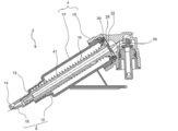
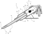
- FIG. 3 is a cross-sectional view of the nozzle device of FIG. 2 and shows the internal structure of the cylinder 4.
- the cylinder 4 includes a cylindrical member 17 and a lid member 15 that closes the rear end opening of the cylindrical member 17.
- the piston slider 6 accommodated in the cylinder 4 is divided into a front slider 10 in which an injection port 14 is formed and a rear slider 12 in which an inflow port 30 is formed, and both are detachably fitted and connected. .
- a flow path 41 that connects the inlet 30 to the injection port 14 is provided inside the piston slider 6.
- a spring 16 that further urges the piston slider 6 in the backward direction is provided in the cylinder 4, and a plate-like shape that receives the water pressure of the washing water flowing into the cylinder 4 is provided around the inlet 30 of the rear slider 12.
- a water pressure receiving portion 19 is provided, and the pressure of the washing water flowing into the cylinder 4 is received by the water pressure receiving portion 19 so that the piston slider 6 moves forward against the urging force of the spring 16. Yes.
- a plate-like water discharge suppression member 22 that contacts the water pressure receiving portion 19 of the rear slider 12 and closes the inlet 30 from the rear is provided. It is comprised so that washing water may flow in. The operation of the water discharge suppressing member 22 will be described in detail later.
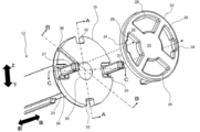
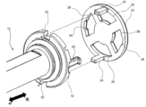
- FIGS. 4 and 5 are enlarged perspective views showing the rear end portion of the rear slider 12 and the water discharge suppression member 22, and FIG. 4 is a view of the rear slider 12 and the water discharge suppression member 22 as viewed from the rear. These are the figures which looked at them from the front.
- a plate-like water pressure receiving portion 19 is formed at the rear end portion of the rear slider 12, and an inflow port 30 is formed at the center thereof.
- the water pressure receiving portion 19 is formed with a communication recess 36 extending from the inlet 30 to the outer surface 39 of the water pressure receiving portion 19.
- the hydraulic pressure receiving portion 19 is provided with two locking hooks 20 having a claw portion 21 at the tip and extending rearward.
- a first recess 32 is provided on the outer surface 39 of the water pressure receiving portion.
- the water discharge suppressing member 22 is provided with an inlet closing portion 33 for closing the inlet 30 of the rear slider 12 from the rear and a communication recess closing portion 35 for closing the communication recess 36 from the rear.
- the opening part 28 is provided in four places of the water discharge suppression member 22 up and down, right and left.
- the left and right openings 28 of the water discharge suppression member 22 are provided with second recesses 34 that are recessed toward the outer periphery, and after the water discharge suppression member 22 is attached, the locking hook 20 of the rear slider 12 is the second recess. 34 is configured to be slidable along the line 34. At this time, since the claw portion 21 is formed at the tip of the locking hook 20, the water discharge suppressing member 22 does not come off naturally.
- the water discharge suppression member 22 is formed with a rod-shaped separation member 24 extending forward, and after the water discharge suppression member 22 is attached to the rear end portion of the rear slider 12, the rear slider Twelve first recesses 32 are configured to be slidable.
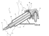
- FIG. 6 is a cross-sectional view when the piston slider 6 is in the retracted position
- FIG. 7 is a cross-sectional view when the piston slider 6 is in the midway position
- FIG. 8 is a cross-sectional view when the piston slider 6 is in a use position
- FIG. 9 is a cross-sectional view when the piston slider 6 is in a position in the middle of retraction.
- FIG. 6 is a line based on the position of the rear end face of the piston slider 6 when the piston slider 6 is in the stored state. Note that both the “open position” and “use position” lines shown in FIG. 8 are based on the position of the rear end face of the piston slider 6. Note that FIG. 6 is a diagram in the same state as FIG. 3, and the description of the overlapping reference numerals is omitted.
- the cylindrical member 17 of the cylinder 4 is formed with a stepped portion 27 and a seal surface 26 in the vicinity of the cylinder opening 13.
- An O-ring 18 made of rubber or the like is attached to the front side of the water pressure receiving portion 19 of the piston slider 6.
- the water discharge suppressing member 22 is closed from the rear by the water pressure suppression member 22 due to the water pressure of the cleaning water flowing into the cylinder 4.
- the washing water in the cylinder 4 can be prevented from flowing into the flow path 41 of the piston slider 6, and the washing water can be prevented from being discharged from the injection port 14 of the piston slider 6.
- the inlet 30 of the piston slider 6 is opened, and cleaning water flows through the opening 28 of the water discharge suppressing member 22 (arrow in FIG. 8).
- the washing water that has flowed into the inlet 30 flows through the flow path 41 inside the piston slider 6 and is jetted from the jet port 14.
- the O-ring 18 of the piston slider 6 seals between the outer peripheral surface of the piston slider 6 and the inner wall surface of the cylinder 4, a gap between the outer peripheral surface of the piston slider 6 and the cylinder opening 13 is used. Wash water does not flow out of Therefore, the water flow of the cleaning water injected from the injection port 14 of the piston slider 6 is not reduced.
- FIG. 10 is a cross-sectional view based on the BB cross section of FIG. 4, and also shows the cylinder and the water discharge suppressing member together.
- the rear end portion of the piston slider 6 has the communication recess 36 and the communication recess closing portion described above. 35) is formed, and the inflow port 30 and the space in the cylinder 4 are always in communication with each other.
- the communication path 40 of the present embodiment is formed to be substantially perpendicular to the axial direction of the cylinder 4.
- the direction of the communication path 40 and the direction in which the washing water pressure is applied can be orthogonal to each other. Therefore, it is difficult for the water pressure of the cleaning water to be applied to the communication path 40, and the advancement operation of the piston slider 6 is not hindered without reducing the water pressure of the cleaning water in the cylinder 4 during the advancement process of the piston slider 6.
- the opening 42 of the communication passage 40 of the present embodiment is formed so as to face the space in the cylinder 4.
- the communication passage 40 of the piston slider 6 is formed in the cylinder 4. The air quickly communicates with the air, and the washing water in the flow path 41 is quickly discharged.
- FIG. 11 is a cross-sectional view based on the BB cross section of FIG. 4, and also shows the cylinder and the water discharge suppressing member together.
- the rear end portion of the piston slider 6 is provided with a locking hook 20 having a claw portion 21 at the front end so that the water discharge suppressing member 22 is not separated from the piston slider 6 by a predetermined distance or more. ing.
- the water discharge suppression member 22 is predetermined by the piston slider 6. Since the water discharge suppression member 22 is not separated by more than the distance, the water discharge suppression member 22 is not properly closed due to rotation in the cylinder 4 or the like.
- the nozzle device according to this embodiment has been described with reference to the drawings.
- the present invention is not limited to this, and can be appropriately designed without departing from the gist of the present invention.
- only one communication path 40 is provided, but a plurality of communication paths 40 may be provided.
- the communication recessed part 36 which comprises the communicating path 40 was provided in the piston slider 6 side, you may provide in the water discharge suppression member 22 side.
- the aspect of the present invention it is possible to suppress the washing water from being discharged from the injection port during the advancement of the hydraulic nozzle with a simple configuration, and after the nozzle is used, the washing water is placed in the flow path.
- a sanitary washing device that can maintain a clean state without leaving any residue.
Landscapes
- Health & Medical Sciences (AREA)
- Public Health (AREA)
- Molecular Biology (AREA)
- Epidemiology (AREA)
- Life Sciences & Earth Sciences (AREA)
- Engineering & Computer Science (AREA)
- Hydrology & Water Resources (AREA)
- Water Supply & Treatment (AREA)
- Bidet-Like Cleaning Device And Other Flush Toilet Accessories (AREA)
- Nozzles (AREA)
Abstract
Description
また、連通路は、ピストンスライダの進出過程においてシリンダ内の洗浄水の圧力を低下させないよう構成されているため、ピストンスライダの進出動作を阻害することがなく、人体洗浄動作をスムーズに行うことができる。
なお、図面は模式的または概念的なものであり、各部分の形状や縦横の寸法の関係、部分間の大きさの比率などは、必ずしも現実のものと同一とは限らない。また、同じ部分を表す場合であっても、図面により互いの寸法や比率が異なって表される場合もある。
なお、本願明細書と各図において、既出の図に関して前述したものと同様の要素には同一の符号を付して詳細な説明は適宜省略する。
図1に示すように、本発明の実施形態による衛生洗浄装置1は、人体を洗浄するノズル装置2と、このノズル装置2を内部に収容するケーシング7と、ケーシング7に回動自在に軸支される便座9と、便座9の上部を覆う便蓋11とから構成されている。また、ケーシング7にはノズル装置2を進退させるための開口部(図示しない)が形成され、その開口部を開閉するノズルシャッター5が設けられている。
また、ケーシング7の内部には、ノズル装置2に供給される洗浄水の供給・停止を切り替えるバルブユニット(図示しない)と、バルブユニットとノズル装置2の間に介在し洗浄水を所定の温度まで温める熱交ユニット(図示しない)とが内蔵されている。
ノズル装置2は、先端部に洗浄水を噴射する噴射口14を有する中空棒状のピストンスライダ6が、シリンダ4内に前後方向進退自在に収納されている。そして、ピストンスライダ6を前方に突出させる際は、シリンダ4の前端部に形成されたシリンダ開口部13から突出させるようにしている。また、シリンダ4は、後端部に給水口8が設けられ、図示しない給水源からバルブユニット、熱交ユニット等を介して洗浄水が給水される。またシリンダ4の下方には図示しないケースプレートに取り付けるための取り付け部3が設けられている。
図3に示すように、シリンダ4は、筒状部材17と、筒状部材17の後端開口を塞ぐ蓋部材15とから構成されている。シリンダ4内に収納されるピストンスライダ6は、噴射口14が形成された前スライダ10と、流入口30が形成された後スライダ12とに分割され、両者は着脱自在に嵌合接続している。そして、このピストンスライダ6の内部には、流入口30から噴射口14までをつなぐ流路41が設けられている。
シリンダ4内には、さらにピストンスライダ6を後退方向に付勢するばね16が設けられ、後スライダ12の流入口30の周囲には、シリンダ4内に流入する洗浄水の水圧を受ける板状の水圧受け部19が設けられ、シリンダ4内に流入する洗浄水の水圧を、この水圧受け部19で受けることで、ピストンスライダ6をばね16の付勢力に逆らって前方に進出させるよう構成されている。
さらに、このとき、ピストンスライダ6のOリング18により、ピストンスライダ6の外周面とシリンダ4の内壁面との間をシールするため、ピストンスライダ6の外周面とシリンダ開口部13との間の隙間から洗浄水が流出することがない。したがって、ピストンスライダ6の噴射口14から噴射される洗浄水の水勢を低下させることがない。
そして、図9に示すように、ピストンスライダ6の後退途中においては、シリンダ4内のピストンスライダ6より後方側に溜まった洗浄水は、水圧受け部19の外周面とシリンダ4の内壁面との間の隙間を介して、水圧受け部19より前方側に流れる。その後、ピストンスライダ6の外周面とシリンダ開口部13との間の隙間からシリンダ4外へ排出される。このように、ピストンスライダ6がばね16の付勢力により後退し、それと共に、シリンダ4内の洗浄水が外へ排出されることで、最終的に図6の収納位置まで戻る。
図10は、図4のB-B断面を基準とした断面図であり、シリンダおよび吐水抑制部材も一緒に図示したものである。
なお、本実施形態の連通路40は、シリンダ4の軸方向に対して、略垂直となるよう形成されている。これにより、シリンダ4内に洗浄水を流入させピストンスライダ6を進出させる過程において、連通路40の方向と洗浄水の水圧がかかる方向とを直交させることができる。したがって、連通路40に洗浄水の水圧がかかりにくくなり、ピストンスライダ6の進出過程でシリンダ4内の洗浄水の水圧を低下させることなく、ピストンスライダ6の進出動作を阻害させることがない。
また、本実施形態の連通路40の開口42は、シリンダ4内の空間の上方に臨むよう形成されている。これにより、ピストンスライダ6の後退途中または後退後に、シリンダ4内の洗浄水が排出されシリンダ4内が徐々に空気で満たされていく過程において、ピストンスライダ6の連通路40が、シリンダ4内の空気と早く連通状態になり、流路41内の洗浄水が早く排出される。
図11は、図4のB-B断面を基準とした断面図であり、シリンダおよび吐水抑制部材も一緒に図示したものである。
これにより、使用者が清掃などをする際に、手でピストンスライダ6先端を引っ張るなどして、ピストンスライダ6を無理やり進出させるようなことがあっても、吐水抑制部材22がピストンスライダ6より所定距離以上離れないため、吐水抑制部材22がシリンダ4内で回転するなどして、吐水抑制部材22の閉止動作が適切に行えなくなるようなことがない。
2 ノズル装置
3 取り付け部
4 シリンダ
5 ノズルシャッター
6 ピストンスライダ
7 ケーシング
8 給水口
9 便座
10 前スライダ
11 便蓋
12 後スライダ
13 シリンダ開口部
14 噴射口
15 蓋部材
16 ばね
17 筒状部材
18 Oリング
19 水圧受け部
20 係止フック
21 爪部
22 吐水抑制部材
24 離間部材
28 開口部
30 流入口
32 第1の凹部
33 流入口閉止部
34 第2の凹部
35 連通凹部閉止部
36 連通凹部
39 外側面
40 連通路
41 流路
42 連通路の開口
Claims (4)
- 給水源から供給される洗浄水を人体に噴射する衛生洗浄装置において、
後端部に第1の流入口を有するシリンダと、
前端部に噴射口と後端部に第2の流入口とを有し、内部に噴射口と第2の流入口とをつなぐ流路を有するピストンスライダと、を備え、
前記シリンダ内には前記ピストンスライダを進退自在に収容すると共に、前記ピストンスライダを後退方向に付勢する付勢手段が設けられ、
前記ピストンスライダの後端部には、前記シリンダ内に流入する洗浄水の水圧を受ける水圧受け部が形成されると共に、前記噴射口からの洗浄水の吐水を抑制する吐水抑制手段が設けられ、
前記第1の流入口よりシリンダ内に流入する洗浄水の圧力を前記ピストンスライダの水圧受け部で受けることで、前記ピストンスライダを付勢手段の付勢力に逆らって使用位置まで進出させるようにしたものであって、
前記ピストンスライダの流路の一部と前記シリンダ内の空間とを常時連通させる連通路が設けられ、
前記連通路は、前記ピストンスライダの進出過程において前記シリンダ内の洗浄水の圧力を低下させないことを特徴とする衛生洗浄装置。 - 前記連通路は、前記シリンダの軸方向に対して略垂直となるよう形成されていることを特徴とする請求項1に記載の衛生洗浄装置。
- 前記連通路の開口は、前記シリンダ内の空間の上方に臨んでいることを特徴とする請求項1に記載の衛生洗浄装置。
- 前記連通路の開口は、前記シリンダ内の空間の上方に臨んでいることを特徴とする請求項2に記載の衛生洗浄装置。
Priority Applications (4)
| Application Number | Priority Date | Filing Date | Title |
|---|---|---|---|
| CN201280051627.9A CN103890287B (zh) | 2011-10-28 | 2012-10-26 | 卫生洗净装置 |
| JP2013540851A JP6075697B2 (ja) | 2011-10-28 | 2012-10-26 | 衛生洗浄装置 |
| BR112014009216-8A BR112014009216B1 (pt) | 2011-10-28 | 2012-10-26 | aparelho com bidê higiênico |
| US14/345,476 US9644361B2 (en) | 2011-10-28 | 2012-10-26 | Sanitary washing apparatus |
Applications Claiming Priority (2)
| Application Number | Priority Date | Filing Date | Title |
|---|---|---|---|
| JP2011-237566 | 2011-10-28 | ||
| JP2011237566 | 2011-10-28 |
Publications (1)
| Publication Number | Publication Date |
|---|---|
| WO2013062097A1 true WO2013062097A1 (ja) | 2013-05-02 |
Family
ID=48167921
Family Applications (1)
| Application Number | Title | Priority Date | Filing Date |
|---|---|---|---|
| PCT/JP2012/077769 Ceased WO2013062097A1 (ja) | 2011-10-28 | 2012-10-26 | 衛生洗浄装置 |
Country Status (5)
| Country | Link |
|---|---|
| US (1) | US9644361B2 (ja) |
| JP (1) | JP6075697B2 (ja) |
| CN (1) | CN103890287B (ja) |
| BR (1) | BR112014009216B1 (ja) |
| WO (1) | WO2013062097A1 (ja) |
Families Citing this family (5)
| Publication number | Priority date | Publication date | Assignee | Title |
|---|---|---|---|---|
| CN104405017B (zh) * | 2014-09-02 | 2016-11-30 | 东莞市联洲知识产权运营管理有限公司 | 一种大小便自动处理设备的清洗装置 |
| US9957704B2 (en) * | 2016-04-15 | 2018-05-01 | 2Go Products Llc | Bidet nozzle insert |
| CN210216624U (zh) * | 2018-02-26 | 2020-03-31 | 爱信精机株式会社 | 私处清洗装置 |
| USD1067394S1 (en) * | 2020-09-30 | 2025-03-18 | Toto Ltd. | Toilet seat |
| JP7713161B2 (ja) * | 2023-05-31 | 2025-07-25 | Toto株式会社 | 衛生洗浄装置及びトイレ装置 |
Citations (3)
| Publication number | Priority date | Publication date | Assignee | Title |
|---|---|---|---|---|
| JPS58169424A (ja) * | 1982-03-31 | 1983-10-05 | 近藤 権士 | 着脱可能のノズルハウジングを備えた便座 |
| JPH09316970A (ja) * | 1996-05-29 | 1997-12-09 | Aisin Seiki Co Ltd | 人体局部洗浄装置のノズル機構 |
| JPH10110459A (ja) * | 1996-10-04 | 1998-04-28 | Toshiba Home Technol Corp | 温水洗浄装置の洗浄ノズル |
Family Cites Families (9)
| Publication number | Priority date | Publication date | Assignee | Title |
|---|---|---|---|---|
| DE2646021C3 (de) * | 1976-10-12 | 1979-05-23 | Hans Zollikerberg Zuerich Maurer (Schweiz) | Unterdusche für Klosetts |
| JPS58134473U (ja) * | 1982-03-08 | 1983-09-09 | ジヤニス工業株式会社 | 衛生洗浄装置用ノズル |
| JP3127609B2 (ja) * | 1992-09-30 | 2001-01-29 | アイシン精機株式会社 | 温水洗浄装置のノズル装置 |
| JPH0762710A (ja) * | 1993-08-30 | 1995-03-07 | Matsushita Electric Works Ltd | 局部洗浄装置用ノズル |
| JP2002097698A (ja) * | 2000-09-26 | 2002-04-02 | Matsushita Electric Works Ltd | 局部洗浄装置 |
| WO2003086160A1 (en) * | 2002-04-08 | 2003-10-23 | Sam Kyun Lim | Portable bidet and nozzle thereof |
| KR101104458B1 (ko) * | 2002-08-29 | 2012-01-12 | 파나소닉 주식회사 | 위생 세정 장치 |
| CN2683725Y (zh) * | 2004-02-27 | 2005-03-09 | 罗毅 | 方便节能洁身器 |
| CN201560480U (zh) * | 2009-11-27 | 2010-08-25 | 中山市美图塑料工业有限公司 | 一种用于排除管道中残留冷水的装置 |
-
2012
- 2012-10-26 CN CN201280051627.9A patent/CN103890287B/zh not_active Expired - Fee Related
- 2012-10-26 WO PCT/JP2012/077769 patent/WO2013062097A1/ja not_active Ceased
- 2012-10-26 BR BR112014009216-8A patent/BR112014009216B1/pt active IP Right Grant
- 2012-10-26 US US14/345,476 patent/US9644361B2/en not_active Expired - Fee Related
- 2012-10-26 JP JP2013540851A patent/JP6075697B2/ja not_active Expired - Fee Related
Patent Citations (3)
| Publication number | Priority date | Publication date | Assignee | Title |
|---|---|---|---|---|
| JPS58169424A (ja) * | 1982-03-31 | 1983-10-05 | 近藤 権士 | 着脱可能のノズルハウジングを備えた便座 |
| JPH09316970A (ja) * | 1996-05-29 | 1997-12-09 | Aisin Seiki Co Ltd | 人体局部洗浄装置のノズル機構 |
| JPH10110459A (ja) * | 1996-10-04 | 1998-04-28 | Toshiba Home Technol Corp | 温水洗浄装置の洗浄ノズル |
Also Published As
| Publication number | Publication date |
|---|---|
| BR112014009216B1 (pt) | 2021-02-09 |
| BR112014009216A2 (pt) | 2020-06-30 |
| US9644361B2 (en) | 2017-05-09 |
| CN103890287A (zh) | 2014-06-25 |
| CN103890287B (zh) | 2016-03-02 |
| US20140352049A1 (en) | 2014-12-04 |
| JP6075697B2 (ja) | 2017-02-08 |
| JPWO2013062097A1 (ja) | 2015-04-02 |
| BR112014009216A8 (pt) | 2017-06-20 |
Similar Documents
| Publication | Publication Date | Title |
|---|---|---|
| JP6075697B2 (ja) | 衛生洗浄装置 | |
| JP5598637B1 (ja) | ノズル装置とそれを使用した衛生洗浄装置 | |
| JP4939983B2 (ja) | ノズル装置及びそれを備えた衛生洗浄装置 | |
| JP4591540B2 (ja) | ノズル装置とそれを使用した衛生洗浄装置 | |
| JP5104625B2 (ja) | ノズル装置とそれを使用した衛生洗浄装置 | |
| JP2021088892A (ja) | 局部洗浄装置及び水洗便器 | |
| JP5626304B2 (ja) | ノズル装置とそれを使用した衛生洗浄装置 | |
| JP4940748B2 (ja) | ノズル装置とそれを使用した衛生洗浄装置 | |
| CN112538886B (zh) | 一种冲洗组件、冲洗组件的排冷方法及智能马桶 | |
| JPH0215700B2 (ja) | ||
| KR102266572B1 (ko) | 변좌용 좌판 및 이를 포함하는 좌판 어셈블리 | |
| CN204919743U (zh) | 人体局部清洗装置 | |
| JP2007239410A (ja) | 衛生洗浄便座装置及びトイレ装置 | |
| JP2008082043A (ja) | ノズル装置とそれを使用した衛生洗浄装置 | |
| JP2906600B2 (ja) | 局部洗浄装置 | |
| JP5093030B2 (ja) | ノズル装置とそれを使用した衛生洗浄装置 | |
| JP4836631B2 (ja) | 衛生洗浄便座装置及びトイレ装置 | |
| JPH09125499A (ja) | 局部洗浄装置 | |
| JP5338020B2 (ja) | ノズル装置とそれを使用した衛生洗浄装置 | |
| KR101554679B1 (ko) | 비데용 노즐 | |
| JP4940819B2 (ja) | ノズル装置とそれを使用した衛生洗浄装置 | |
| JP5167166B2 (ja) | 局部洗浄装置 | |
| JP2568542Y2 (ja) | 人体局部洗浄装置 | |
| JP4840194B2 (ja) | 衛生洗浄装置 | |
| JP2002097698A (ja) | 局部洗浄装置 |
Legal Events
| Date | Code | Title | Description |
|---|---|---|---|
| 121 | Ep: the epo has been informed by wipo that ep was designated in this application |
Ref document number: 12843051 Country of ref document: EP Kind code of ref document: A1 |
|
| WWE | Wipo information: entry into national phase |
Ref document number: 14345476 Country of ref document: US |
|
| ENP | Entry into the national phase |
Ref document number: 2013540851 Country of ref document: JP Kind code of ref document: A |
|
| NENP | Non-entry into the national phase |
Ref country code: DE |
|
| REG | Reference to national code |
Ref country code: BR Ref legal event code: B01A Ref document number: 112014009216 Country of ref document: BR |
|
| 122 | Ep: pct application non-entry in european phase |
Ref document number: 12843051 Country of ref document: EP Kind code of ref document: A1 |
|
| ENP | Entry into the national phase |
Ref document number: 112014009216 Country of ref document: BR Kind code of ref document: A2 Effective date: 20140415 |
|
| ENPC | Correction to former announcement of entry into national phase, pct application did not enter into the national phase |
Ref country code: BR Free format text: ANULADA A PUBLICACAO CODIGO 1.3 NA RPI NO 2423 DE 13/06/2017 POR TER SIDO INDEVIDA. |
|
| REG | Reference to national code |
Ref country code: BR Ref legal event code: B01E Ref document number: 112014009216 Country of ref document: BR Kind code of ref document: A8 Free format text: APRESENTE A TRADUCAO SIMPLES DA FOLHA DE ROSTO DA CERTIDAO DE DEPOSITO DA PRIORIDADE JP 2011-237566; OU DECLARACAO DE QUE OS DADOS DO PEDIDO INTERNACIONAL ESTAO FIELMENTE CONTIDOS NA PRIORIDADE REIVINDICADA, CONTENDO TODOS OS DADOS IDENTIFICADORES DESTA (TITULARES, NUMERO DE REGISTRO, DATA E TITULO), CONFORME O PARAGRAFO UNICO DO ART. 25 DA RESOLUCAO 77/2013 E ART. 2O DA RESOLUCAO 179/2017. CABE SALIENTAR QUE NAO FOI POSSIVEL IDENTIFICAR OS TITULARES DO PEDIDO PRIORITARIO NOS DOCUMENTOS JUNTADOS AO PROCESSO, TAMPOUCO NOS APRESENTADOS NA OMPI. TAL INFORMACAO E NECESSARIA PARA O EXAME DA CESSAO DO DOCUMENTO DE PRIORIDADE. |
|
| ENP | Entry into the national phase |
Ref document number: 112014009216 Country of ref document: BR Kind code of ref document: A2 Effective date: 20140415 |