WO2013062064A1 - 炊飯器 - Google Patents
炊飯器 Download PDFInfo
- Publication number
- WO2013062064A1 WO2013062064A1 PCT/JP2012/077659 JP2012077659W WO2013062064A1 WO 2013062064 A1 WO2013062064 A1 WO 2013062064A1 JP 2012077659 W JP2012077659 W JP 2012077659W WO 2013062064 A1 WO2013062064 A1 WO 2013062064A1
- Authority
- WO
- WIPO (PCT)
- Prior art keywords
- main body
- rice cooker
- cord
- plug portion
- power cord
- Prior art date
- Legal status (The legal status is an assumption and is not a legal conclusion. Google has not performed a legal analysis and makes no representation as to the accuracy of the status listed.)
- Ceased
Links
Images



Classifications
-
- A—HUMAN NECESSITIES
- A47—FURNITURE; DOMESTIC ARTICLES OR APPLIANCES; COFFEE MILLS; SPICE MILLS; SUCTION CLEANERS IN GENERAL
- A47J—KITCHEN EQUIPMENT; COFFEE MILLS; SPICE MILLS; APPARATUS FOR MAKING BEVERAGES
- A47J36/00—Parts, details or accessories of cooking-vessels
Definitions
- the present invention relates to a rice cooker, and more particularly to a connection structure of a power cord to a rice cooker body.
- Patent Document 1 As a conventional rice cooker, insert the power plug into the power plug connecting device that supplies power to the heater and connect it, and when inserting the power plug into the power plug connecting device, you can check the insertion rib of the power plug.
- Patent Document 1 There is one provided (for example, Patent Document 1).
- connection portion of the power plug since the connection portion of the power plug is provided in the vicinity of the outer shell of the main body, there is not much in the root portion (connection portion) of the cord connected to the power plug. The problem is that the cord is damaged, causing a short circuit or a breakdown of the rice cooker itself.
- root part (bush etc.) of the cord connected to the power plug since the root part (bush etc.) of the cord connected to the power plug has a structure where it protrudes from the outer shell of the rice cooker body to the outside, rice spills over the root part or when cooking There is a problem that there is always a risk of contamination such as spillage of water, or accumulation of dust etc. even when not in use.
- the present invention has been made to solve the problems as described above, and a first object of the present invention is to reduce the risk of dirt adhering to the root portion (connection portion) of the cord connected to the plug portion. To get the The second object is to obtain a rice cooker which reduces stress due to bending of a power cord.
- the rice cooker according to the present invention comprises: a main body for accommodating an inner pot into which the food is put; and a power cord connected to the bottom of the main body to mediate power supply from an external power source to the main body.
- the connection of the power cord to the body fits within the projection plane of the bottom of the body.
- connection portion of the power cord to the main body fits within the projection plane of the bottom surface of the main body, so it is possible to suppress the occurrence of contamination due to spilled rice or water at the connection portion. Can reduce the risk of contamination.
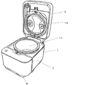
- FIG. 1 is an external perspective view of a rice cooker according to Embodiment 1 of the present invention
- FIG. 2 is a view showing a state where a lid 2 of the rice cooker is opened.
- FIG.1 and FIG.2 the outline of a structure of the rice cooker which concerns on this Embodiment is demonstrated, referring FIG.1 and FIG.2.
- the main body 1 of the rice cooker forms a lid 2 covering the upper surface of the rice cooker and an outer shell of the middle part of the rice cooker.
- the main body 1 has a substantially rectangular parallelepiped shape.
- the lid 2 is rotatably connected to the main body side case 7 on the rear side of the main body 1. Further, the lid 2 has a lid opening button 5 on its front surface, the operation unit 4 and the display unit 6 on its top surface, and an inner lid 14 (see FIG. 2) on its bottom surface.
- the lid opening button 5 is for opening the lid 2 by being pressed by the user.
- the operation unit 4 is for starting a cooking process and the like for a cooked material such as rice introduced into the inner pot 11.
- the operation unit 4 generates an operation signal by being operated by the user, and transmits the operation signal to a control board (not shown) installed in the main body 1.
- the display unit 6 displays the progress of the above-mentioned rice cooking process, displays a clock, displays an abnormality, and the like.
- the inner lid 14 covers the opening of the inner hook 11 when the lid 2 is in the closed state.
- the inner hook 11 can be removably stored in the main body side surface case 7.
- the user places the food such as rice into the inner pot 11, closes the lid 2, and the rice cooking start operation is performed in the operation unit 4, whereby the rice cooking process is performed.
- the inner pot 11 receives induction heating from the heating coil (not shown), and cooking of the input food is carried out.
- FIG. 3 is a bottom view of the rice cooker according to the first embodiment of the present invention and a view showing a state where the detachable power cord 61 is connected
- FIG. 4 is a bottom view of the rice cooker. It is a figure which shows the state from which the detachable power cord 61 was removed
- FIG. 5 is an enlarged view of the inlet structure 63 peripheral part in the bottom view of the rice cooker.
- the upper part in the drawing is the front of the rice cooker, and the lower part is the rear of the rice cooker.
- the bottom surface of the rice cooker according to the present embodiment is formed by the bottom surface case 8, and an inlet structure for inserting the detachable power cord 61 into the bottom surface case 8. 63 are installed.
- the detachable power cord 61 mediates the supply of power from the outside to the rice cooker according to the present embodiment, and is constituted by the plug portion 65, the cord portion 64 and the bush 62.
- the plug portion 65 is a portion detachably inserted into the inlet 63 a of the inlet structure 63 described later, and supplies power to the rice cooker according to the present embodiment via the cord portion 64.
- the bush 62 is attached to a connection portion between the plug portion 65 and the cord portion 64, and reduces stress due to bending of the cord portion 64 in the connection portion.
- the inlet structure 63 has an inlet 63a for inserting the plug portion 65 of the detachable power cord 61, and the power supplied from the plug portion 65 can be used as a control board or the like in the rice cooker of the present embodiment. It has a structure for developing and supplying electrical components. Further, in the inlet structure 63, in the vicinity of the corner of the bottom surface of the main body 1, the insertion direction of the plug portion 65 into the inlet 63a is a direction inclined with respect to both the width direction and the depth direction of the main body 1. It is arranged as. Furthermore, in the inlet structure 63, as shown in FIG. 3, when the plug portion 65 is inserted into the inlet 63a, the plug portion 65 and the bush 62 of the detachable power cord 61 are within the projection plane of the bottom surface of the main body 1. It is arranged to fit within.
- the inlet structure 63 is disposed such that the plugging direction of the plug portion 65 into the inlet 63a is inclined with respect to both the width direction and the depth direction of the main body 1, and
- the plug portion 65 and the bush 62 of the detachable power cord 61 are disposed so as to fit within the projection plane of the bottom surface of the main body 1, whereby the plug portion 65 and the cord portion It is possible to reduce the stress due to bending of the cord portion 64 at the connecting portion with 64.
- the inlet structure 63 is disposed in the vicinity of the corner of the bottom surface of the main body 1, and the plug portion 65 is disposed so that the insertion direction of the plug portion 65 is inclined as described above.
- the insertion length of the main body 1 of the detachable power cord 61 in the width direction and the depth direction is the width direction or the depth direction by being arranged so as to be accommodated within the projection plane of the bottom surface of the main body 1 Therefore, the space in the bottom case 8 can be effectively utilized.
- the inlet structure 63 is arranged such that the plug portion 65 and the bush 62 are contained in the projection plane of the bottom surface of the main body 1 so that the bush 62 which is a connection portion between the plug portion 65 and the cord portion 64 Alternatively, the occurrence of soiling due to water spilling can be suppressed, and the risk of soiling can be reduced.
- the plugging direction of the plug portion 65 of the detachable power cord 61 into the inlet 63a does not have to be parallel to the bottom surface of the bottom case 8 so long as there is no problem in mounting the body 1, the main body
- the direction of insertion of the plug portion 65 into the inlet 63 a is not limited in relation to the bottom surface of the bottom case 8.
- the detachable power supply cord 61 separate from the main body 1 is used, the present invention is limited thereto. It is not a thing. That is, instead of being detachable, it may be a fixedly connected direct-attached type power cord. Also in this case, the fixed connection portion is disposed in the vicinity of the corner of the main body 1 and the connection direction of the power supply cord is inclined in the same manner as described above, and the connection portion such as the bush is of the main body 1 If arranged so as to be within the projection plane of the bottom surface, the same effect as described above can be obtained.
- the detachable power cord 61 as in the present embodiment, there is an advantage that replacement is possible due to deterioration, damage or the like of the detachable power cord 61.
- the main body 1 can be carried in a state where the detachable power cord 61 is removed from the main body 1, there is also an advantage that usability is improved.
Landscapes
- Engineering & Computer Science (AREA)
- Food Science & Technology (AREA)
- Cookers (AREA)
Abstract
Description
また、電源プラグに接続されているコードの根元部(ブッシュ等)が、炊飯器本体の外郭から外部に飛び出している構造であるため、その根元部の上部に、ご飯がこぼれ落ちたり、炊飯時において水がこぼれたり、あるいは、不使用時においても埃等が堆積する等の常に汚れに対してのリスクが存在するという問題点があった。
また、第2の目的は、電源コードの折り曲げによるストレスを軽減する炊飯器を得ることである。
(炊飯器の概略構成)
図1は、本発明の実施の形態1に係る炊飯器の外観斜視図であり、図2は、同炊飯器の蓋2が開いた状態を示す図である。以下、図1及び図2を参照しながら、本実施の形態に係る炊飯器の構成の概略について説明する。
操作部4は、内釜11に投入された米等の調理物に対する炊飯工程等を開始させるためのものである。この操作部4は、使用者によって操作されることによって、操作信号を生成し、その操作信号を本体1内に設置されている制御基板(図示せず)に送信する。
表示部6は、前述の炊飯工程の進捗状況の表示、時計表示、及び異常表示等をするものである。
内蓋14は、蓋2が閉状態の場合に、内釜11の開口部を覆うものである。
図3は、本発明の実施の形態1に係る炊飯器の底面図、かつ、着脱式電源コード61が接続された状態を示す図であり、図4は、同炊飯器の底面図、かつ、着脱式電源コード61が取り外された状態を示す図であり、そして、図5は、同炊飯器の底面図におけるインレット構造体63周辺部の拡大図である。以下、図3~図5を参照しながら、本実施の形態に係る炊飯器のインレット構造体63の構成及び着脱式電源コード61の接続態様について説明する。
以上の構成のように、インレット構造体63が、インレット63aへのプラグ部65の差し込み方向が、本体1の幅方向及び奥行き方向の双方に対して傾斜した方向となるように配置され、かつ、プラグ部65がインレット63aに差し込まれた場合、着脱式電源コード61のプラグ部65及びブッシュ62が、本体1の底面の投影面内に収まるように配置されることによって、プラグ部65とコード部64との接続部分におけるコード部64の折り曲げによるストレスを軽減することが可能となる。
Claims (3)
- 調理物が入れられる内釜を収容する本体と、
該本体の底面側に接続され、外部電源から前記本体への電源供給を媒介する電源コードと、
を備え、
該電源コードの前記本体への接続部分が、前記本体の底面の投影面内に収まる
ことを特徴とする炊飯器。 - 前記本体の底面は、略矩形状であり、
前記電源コードは、前記本体の底面の角部近傍に接続され、
前記電源コードの前記本体への接続方向が、前記本体の幅方向及び奥行き方向の双方に対して傾斜した方向である
ことを特徴とする請求項1記載の炊飯器。 - 前記電源コードは、前記本体に着脱自在に接続されるプラグ部、該プラグ部に接続されたコード部、及び、前記プラグ部と前記コード部との接続部分に取り付けられたブッシュによって構成された着脱式電源コードであり、
前記本体の底面には、前記プラグ部が差し込まれて接続されるインレットが形成され、
前記プラグ部が前記インレットに接続された場合、前記プラグ部及び前記ブッシュが、前記本体の底面の投影内面内に収まる
ことを特徴とする請求項1又は請求項2記載の炊飯器。
Priority Applications (1)
| Application Number | Priority Date | Filing Date | Title |
|---|---|---|---|
| CN201290000924.6U CN203935019U (zh) | 2011-10-27 | 2012-10-25 | 电饭煲 |
Applications Claiming Priority (2)
| Application Number | Priority Date | Filing Date | Title |
|---|---|---|---|
| JP2011235631 | 2011-10-27 | ||
| JP2011-235631 | 2011-10-27 |
Publications (1)
| Publication Number | Publication Date |
|---|---|
| WO2013062064A1 true WO2013062064A1 (ja) | 2013-05-02 |
Family
ID=48167890
Family Applications (1)
| Application Number | Title | Priority Date | Filing Date |
|---|---|---|---|
| PCT/JP2012/077659 Ceased WO2013062064A1 (ja) | 2011-10-27 | 2012-10-25 | 炊飯器 |
Country Status (3)
| Country | Link |
|---|---|
| JP (1) | JPWO2013062064A1 (ja) |
| CN (1) | CN203935019U (ja) |
| WO (1) | WO2013062064A1 (ja) |
Cited By (1)
| Publication number | Priority date | Publication date | Assignee | Title |
|---|---|---|---|---|
| JP2015181663A (ja) * | 2014-03-24 | 2015-10-22 | 三菱電機株式会社 | 炊飯器 |
Citations (5)
| Publication number | Priority date | Publication date | Assignee | Title |
|---|---|---|---|---|
| JPS63154108A (ja) * | 1986-12-19 | 1988-06-27 | 松下電器産業株式会社 | 電気調理器 |
| JPH0759664A (ja) * | 1993-08-23 | 1995-03-07 | Matsushita Electric Ind Co Ltd | 調理器の電源コード接続装置 |
| JP2570950Y2 (ja) * | 1992-07-01 | 1998-05-13 | 象印マホービン株式会社 | マグネットプラグ付電源コードを備えた電気器具 |
| JP2000175817A (ja) * | 1998-12-14 | 2000-06-27 | Sanyo Electric Co Ltd | 電気ポット |
| JP2010273937A (ja) * | 2009-05-29 | 2010-12-09 | Tiger Vacuum Bottle Co Ltd | 電気炊飯器 |
-
2012
- 2012-10-25 JP JP2013540834A patent/JPWO2013062064A1/ja active Pending
- 2012-10-25 WO PCT/JP2012/077659 patent/WO2013062064A1/ja not_active Ceased
- 2012-10-25 CN CN201290000924.6U patent/CN203935019U/zh not_active Expired - Fee Related
Patent Citations (5)
| Publication number | Priority date | Publication date | Assignee | Title |
|---|---|---|---|---|
| JPS63154108A (ja) * | 1986-12-19 | 1988-06-27 | 松下電器産業株式会社 | 電気調理器 |
| JP2570950Y2 (ja) * | 1992-07-01 | 1998-05-13 | 象印マホービン株式会社 | マグネットプラグ付電源コードを備えた電気器具 |
| JPH0759664A (ja) * | 1993-08-23 | 1995-03-07 | Matsushita Electric Ind Co Ltd | 調理器の電源コード接続装置 |
| JP2000175817A (ja) * | 1998-12-14 | 2000-06-27 | Sanyo Electric Co Ltd | 電気ポット |
| JP2010273937A (ja) * | 2009-05-29 | 2010-12-09 | Tiger Vacuum Bottle Co Ltd | 電気炊飯器 |
Cited By (1)
| Publication number | Priority date | Publication date | Assignee | Title |
|---|---|---|---|---|
| JP2015181663A (ja) * | 2014-03-24 | 2015-10-22 | 三菱電機株式会社 | 炊飯器 |
Also Published As
| Publication number | Publication date |
|---|---|
| CN203935019U (zh) | 2014-11-12 |
| JPWO2013062064A1 (ja) | 2015-04-02 |
Similar Documents
| Publication | Publication Date | Title |
|---|---|---|
| KR200391155Y1 (ko) | 온도감지 및 표시 기능이 있는 분리형 조리용기의손잡이 | |
| JP6229171B2 (ja) | 加熱調理器 | |
| JP6128380B2 (ja) | 炊飯器 | |
| US9801497B2 (en) | Electric frying pan | |
| WO2013062064A1 (ja) | 炊飯器 | |
| KR101202930B1 (ko) | 조리용기의 탈,부착 손잡이 | |
| CN109567579B (zh) | 压力式煮饭器 | |
| JP2014213057A (ja) | 炊飯器 | |
| JP2014074572A (ja) | 加熱調理器 | |
| JP2018017703A (ja) | 計量装置及びこれを備えた炊飯システム | |
| JP6456128B2 (ja) | 内釜および炊飯器 | |
| CN100577073C (zh) | 整体烤盘结构 | |
| JP4288606B2 (ja) | 組込式加熱調理器 | |
| KR20180087023A (ko) | 히팅 기능을 갖는 컵 홀더 | |
| JP5332844B2 (ja) | 炊飯器 | |
| CN103987145B (zh) | 一体式智能电磁加热锅具组件 | |
| JP4889372B2 (ja) | 誘導加熱調理器 | |
| JP2020195671A (ja) | 炊飯器 | |
| JP6175687B2 (ja) | 炊飯器 | |
| JP2010236749A (ja) | 加熱調理器 | |
| KR200455437Y1 (ko) | 그릴장치 | |
| JP2007143894A (ja) | 炊飯器 | |
| CN211270183U (zh) | 一种食物处理机 | |
| JP6727057B2 (ja) | 加熱調理器 | |
| US20060289443A1 (en) | Household electric heating cooker with detachable power outlet |
Legal Events
| Date | Code | Title | Description |
|---|---|---|---|
| WWE | Wipo information: entry into national phase |
Ref document number: 201290000924.6 Country of ref document: CN |
|
| 121 | Ep: the epo has been informed by wipo that ep was designated in this application |
Ref document number: 12842763 Country of ref document: EP Kind code of ref document: A1 |
|
| ENP | Entry into the national phase |
Ref document number: 2013540834 Country of ref document: JP Kind code of ref document: A |
|
| NENP | Non-entry into the national phase |
Ref country code: DE |
|
| 122 | Ep: pct application non-entry in european phase |
Ref document number: 12842763 Country of ref document: EP Kind code of ref document: A1 |