WO2013061920A1 - ブレーキ制御システム - Google Patents
ブレーキ制御システム Download PDFInfo
- Publication number
- WO2013061920A1 WO2013061920A1 PCT/JP2012/077230 JP2012077230W WO2013061920A1 WO 2013061920 A1 WO2013061920 A1 WO 2013061920A1 JP 2012077230 W JP2012077230 W JP 2012077230W WO 2013061920 A1 WO2013061920 A1 WO 2013061920A1
- Authority
- WO
- WIPO (PCT)
- Prior art keywords
- brake control
- control system
- valve
- brake
- front wheel
- Prior art date
- Legal status (The legal status is an assumption and is not a legal conclusion. Google has not performed a legal analysis and makes no representation as to the accuracy of the status listed.)
- Ceased
Links
Images

Classifications
-
- B—PERFORMING OPERATIONS; TRANSPORTING
- B60—VEHICLES IN GENERAL
- B60T—VEHICLE BRAKE CONTROL SYSTEMS OR PARTS THEREOF; BRAKE CONTROL SYSTEMS OR PARTS THEREOF, IN GENERAL; ARRANGEMENT OF BRAKING ELEMENTS ON VEHICLES IN GENERAL; PORTABLE DEVICES FOR PREVENTING UNWANTED MOVEMENT OF VEHICLES; VEHICLE MODIFICATIONS TO FACILITATE COOLING OF BRAKES
- B60T7/00—Brake-action initiating means
- B60T7/02—Brake-action initiating means for personal initiation
- B60T7/04—Brake-action initiating means for personal initiation foot actuated
- B60T7/042—Brake-action initiating means for personal initiation foot actuated by electrical means, e.g. using travel or force sensors
-
- B—PERFORMING OPERATIONS; TRANSPORTING
- B60—VEHICLES IN GENERAL
- B60T—VEHICLE BRAKE CONTROL SYSTEMS OR PARTS THEREOF; BRAKE CONTROL SYSTEMS OR PARTS THEREOF, IN GENERAL; ARRANGEMENT OF BRAKING ELEMENTS ON VEHICLES IN GENERAL; PORTABLE DEVICES FOR PREVENTING UNWANTED MOVEMENT OF VEHICLES; VEHICLE MODIFICATIONS TO FACILITATE COOLING OF BRAKES
- B60T13/00—Transmitting braking action from initiating means to ultimate brake actuator with power assistance or drive; Brake systems incorporating such transmitting means, e.g. air-pressure brake systems
- B60T13/10—Transmitting braking action from initiating means to ultimate brake actuator with power assistance or drive; Brake systems incorporating such transmitting means, e.g. air-pressure brake systems with fluid assistance, drive, or release
- B60T13/12—Transmitting braking action from initiating means to ultimate brake actuator with power assistance or drive; Brake systems incorporating such transmitting means, e.g. air-pressure brake systems with fluid assistance, drive, or release the fluid being liquid
- B60T13/16—Transmitting braking action from initiating means to ultimate brake actuator with power assistance or drive; Brake systems incorporating such transmitting means, e.g. air-pressure brake systems with fluid assistance, drive, or release the fluid being liquid using pumps directly, i.e. without interposition of accumulators or reservoirs
- B60T13/161—Systems with master cylinder
- B60T13/165—Master cylinder integrated or hydraulically coupled with booster
- B60T13/166—Part of the system directly actuated by booster pressure
-
- B—PERFORMING OPERATIONS; TRANSPORTING
- B60—VEHICLES IN GENERAL
- B60T—VEHICLE BRAKE CONTROL SYSTEMS OR PARTS THEREOF; BRAKE CONTROL SYSTEMS OR PARTS THEREOF, IN GENERAL; ARRANGEMENT OF BRAKING ELEMENTS ON VEHICLES IN GENERAL; PORTABLE DEVICES FOR PREVENTING UNWANTED MOVEMENT OF VEHICLES; VEHICLE MODIFICATIONS TO FACILITATE COOLING OF BRAKES
- B60T7/00—Brake-action initiating means
- B60T7/02—Brake-action initiating means for personal initiation
- B60T7/08—Brake-action initiating means for personal initiation hand actuated
- B60T7/085—Brake-action initiating means for personal initiation hand actuated by electrical means, e.g. travel, force sensors
-
- B—PERFORMING OPERATIONS; TRANSPORTING
- B60—VEHICLES IN GENERAL
- B60T—VEHICLE BRAKE CONTROL SYSTEMS OR PARTS THEREOF; BRAKE CONTROL SYSTEMS OR PARTS THEREOF, IN GENERAL; ARRANGEMENT OF BRAKING ELEMENTS ON VEHICLES IN GENERAL; PORTABLE DEVICES FOR PREVENTING UNWANTED MOVEMENT OF VEHICLES; VEHICLE MODIFICATIONS TO FACILITATE COOLING OF BRAKES
- B60T8/00—Arrangements for adjusting wheel-braking force to meet varying vehicular or ground-surface conditions, e.g. limiting or varying distribution of braking force
- B60T8/26—Arrangements for adjusting wheel-braking force to meet varying vehicular or ground-surface conditions, e.g. limiting or varying distribution of braking force characterised by producing differential braking between front and rear wheels
- B60T8/261—Arrangements for adjusting wheel-braking force to meet varying vehicular or ground-surface conditions, e.g. limiting or varying distribution of braking force characterised by producing differential braking between front and rear wheels specially adapted for use in motorcycles
-
- B—PERFORMING OPERATIONS; TRANSPORTING
- B60—VEHICLES IN GENERAL
- B60T—VEHICLE BRAKE CONTROL SYSTEMS OR PARTS THEREOF; BRAKE CONTROL SYSTEMS OR PARTS THEREOF, IN GENERAL; ARRANGEMENT OF BRAKING ELEMENTS ON VEHICLES IN GENERAL; PORTABLE DEVICES FOR PREVENTING UNWANTED MOVEMENT OF VEHICLES; VEHICLE MODIFICATIONS TO FACILITATE COOLING OF BRAKES
- B60T8/00—Arrangements for adjusting wheel-braking force to meet varying vehicular or ground-surface conditions, e.g. limiting or varying distribution of braking force
- B60T8/32—Arrangements for adjusting wheel-braking force to meet varying vehicular or ground-surface conditions, e.g. limiting or varying distribution of braking force responsive to a speed condition, e.g. acceleration or deceleration
- B60T8/34—Arrangements for adjusting wheel-braking force to meet varying vehicular or ground-surface conditions, e.g. limiting or varying distribution of braking force responsive to a speed condition, e.g. acceleration or deceleration having a fluid pressure regulator responsive to a speed condition
- B60T8/40—Arrangements for adjusting wheel-braking force to meet varying vehicular or ground-surface conditions, e.g. limiting or varying distribution of braking force responsive to a speed condition, e.g. acceleration or deceleration having a fluid pressure regulator responsive to a speed condition comprising an additional fluid circuit including fluid pressurising means for modifying the pressure of the braking fluid, e.g. including wheel driven pumps for detecting a speed condition, or pumps which are controlled by means independent of the braking system
- B60T8/4072—Systems in which a driver input signal is used as a control signal for the additional fluid circuit which is normally used for braking
- B60T8/4081—Systems with stroke simulating devices for driver input
Definitions
- the present invention relates to a brake control system capable of interlocking braking of a second wheel by operating a pump in conjunction with braking of the first wheel.
- the simulator includes a simulator valve, a check valve, and a simulator chamber, and pistons and springs are used in the simulator chamber, resulting in a large number of parts and a complicated configuration. It was. Further, in such a brake control system, it is necessary to control the opening and closing of the simulator valve, and the control is complicated.
- An object of the present invention is to provide a brake control system that can solve the above-described problems of the prior art and can simplify the structure for preventing the brake operation feeling from becoming hard at the time of brake interlocking braking. It is in.
- the present invention relates to a brake control system capable of interlocking braking of a second wheel by operating a pump in conjunction with braking of the first wheel, in order to brake the suction side of the pump and the second wheel.
- a hydraulic storage circuit that is connected to a hydraulic circuit between the hydraulic cylinder and a non-return valve, and stores the brake fluid of the hydraulic circuit when the master cylinder is actuated during interlocking braking.
- the liquid portion includes a liquid storage chamber in which the brake fluid is stored, and a piston that adjusts the volume of the liquid storage chamber, and the check valve closes a flow path that communicates with the liquid storage chamber.
- the valve body comes into close contact, it is provided so as to prevent the flow of fluid from the hydraulic circuit to the liquid storage chamber, and the piston passes through the flow path and hits the valve body.
- a rod for separating from the flow path was provided. And wherein the door.
- the rod may be longer than the flow path.
- the liquid storage unit may be connected to the hydraulic circuit between the suction side of the pump and the master cylinder via a relief valve provided in parallel with the check valve.
- the anti-lock brake control may be provided, and the relief valve may be opened during the anti-lock brake control to communicate the hydraulic circuit with the cylinder.
- the relief valve may not be opened by the operation of the master cylinder.
- the liquid reservoir may include a spring for pushing the piston into the flow path. The spring may not push the piston into the flow path when the rod is in contact with the valve body.
- the piston may have an O-ring wound around its outer periphery.
- the liquid storage chamber may be a cylinder.
- the present invention it is possible to simplify the structure for preventing the brake operation feeling from becoming hard at the time of brake interlocking braking.
- FIG. 1 is a circuit diagram showing a hydraulic circuit of a brake control system according to the present embodiment.
- the brake control system 400 is mounted on a motorcycle and drives the front wheel hydraulic circuit 100, the rear wheel hydraulic circuit 200, and the hydraulic pumps 119 and 219 of the front wheel hydraulic circuit 100 and the rear wheel hydraulic circuit 200.
- DC motor 300 is provided.
- the hydraulic circuits 100 and 200 are filled with brake fluid.
- region enclosed with the dashed-dotted line in the figure has shown having integrated in one unit.
- the front wheel hydraulic circuit 100 is connected to a brake lever 101 that is operated with the driver's right hand, a front wheel master cylinder 103 that pressurizes the front wheel hydraulic circuit 100 when the brake lever 101 is operated, and a front wheel master cylinder 103.
- And an intake valve 109 And an intake valve 109.
- a filter is provided at each of the connection portion between the pipe line 104 and the front wheel side switching valve 107 and the connection portion between the pipe line 104 and the front wheel side intake valve 109.
- a pressure sensor 111 is provided in the pipe line 104.
- the pressure sensor 111 detects a pressure between the front wheel side master cylinder 103 and the front wheel side switching valve 107 and the front wheel side intake valve 109, and is an electronic control unit. It is provided to transmit a signal based on the detection result to a certain ECU.
- the front wheel side containment valve 113 is connected to the pipe line 104.
- a filter is also provided at the connection between the front wheel side valve 113 and the pipe line 104.
- the front wheel side fitting valve 113 is connected to the wheel cylinder of the front wheel side caliper 115 via a pipe line 114.
- the front wheel brake is operated by the front wheel hydraulic circuit 100.
- the front wheel brake includes a front wheel caliper 115.
- the front wheel caliper 115 is connected via the front wheel side valve 113 and the conduit 114 as described above.
- the discharge side of the front wheel side hydraulic pump 119 is connected to the pipe line 106 through a throttle.
- the suction side of the front wheel side hydraulic pump 119 is connected to the pipe line 120 through a filter.
- the front wheel hydraulic pump 119 is driven by the DC motor 300.
- One end of a front wheel check valve 121 is connected to the pipe line 120.
- a discharge port of the front wheel side suction valve 109 is connected to the pipe line 120.
- the other end of the front wheel side check valve 121 is connected to the pipe line 122.
- the front wheel side check valve 121 is disposed so as to prevent a backflow from the pipe line 120 to the pipe line 122.
- the discharge port of the front wheel side relaxation valve 123 is connected to the pipe line 122.
- a front wheel side accumulator 125 is connected to the pipe line 122 between a front wheel side check valve 121 and a front wheel side relaxation valve 123.
- the front wheel side caliper 115 is connected to the inflow port of the front wheel side relaxation valve 123 via the pipe line 114.
- the outflow port of the front wheel side relaxation valve 123 is connected to the pipe line 122.
- a filter is provided at a connection portion between the inflow port of the front wheel side relaxation valve 123 and the pipe line 114.
- a pressure sensor 127 is provided in the pipe line 114, and the pressure sensor 127 measures the pressure in the pipe line 114 and transmits a pressure signal to the ECU.
- the rear wheel hydraulic circuit 200 includes a brake pedal 201 that is operated with the right foot of the driver, a rear wheel master cylinder 203 that pressurizes the rear wheel hydraulic circuit 200 when the brake pedal 201 is operated, and a rear wheel master.
- the rear wheel side master cylinder reservoir 205 connected to the cylinder 203, the rear wheel side switching valve 207 connected to the rear wheel side master cylinder 203 via the conduit 204, and the rear wheel side master via the conduit 204
- a rear wheel side intake valve 209 connected to the cylinder 203.
- a filter is provided at each of the connection portion between the pipeline 204 and the rear wheel side switching valve 207 and the connection portion between the pipeline 204 and the rear wheel side intake valve 209.
- a pressure sensor 211 is provided in the pipe line 204, and the pressure sensor 211 detects the pressure between the rear wheel side master cylinder 203, the rear wheel side switching valve 207, and the rear wheel side intake valve 209, and the ECU A signal based on the detection result is transmitted.
- the rear wheel side valve 213 is connected via a rear wheel side switching valve 207 and a pipe line 206. Filters are also provided at the connection portions between the rear wheel side switching valve 207 and the rear wheel side insertion valve 213 and the pipe line 206, respectively.
- the rear wheel side valve 213 is connected to a wheel cylinder of the rear wheel caliper 215 via a pipe line 214.
- the rear wheel brake includes a rear wheel caliper 215.
- the rear wheel caliper 215 is connected via the rear wheel side insertion valve 213 and the pipe line 214 as described above.
- the discharge side of the rear wheel side hydraulic pump 219 is connected to the pipe line 206 via a throttle.
- the suction side of the rear wheel side hydraulic pump 219 is connected to the pipeline 220 through a filter.
- the rear wheel hydraulic pump 219 is driven by the DC motor 300.
- one end of a rear wheel check valve 221 is connected to the pipe line 220.
- a discharge port of the rear wheel side intake valve 209 is connected to the pipe line 220.
- the other end of the rear wheel check valve 221 is connected to the pipe line 222.
- the rear wheel side check valve 221 is arranged so as to prevent a backflow from the pipe line 220 to the pipe line 222.
- the discharge port of the rear wheel side relaxation valve 223 is connected to the pipe line 222.
- a rear wheel side accumulator 225 is connected to the pipe line 222 between the rear wheel side check valve 221 and the rear wheel side relaxation valve 223.
- the rear wheel caliper 215 is connected to the inflow port of the rear wheel side relief valve 223 via the pipe line 214.
- the outflow port of the rear wheel side relaxation valve 223 is connected to the pipe line 222.
- a filter is provided at the outflow port of the rear wheel side relaxation valve 223, the pipe line 214, and the connection portion.
- a pressure sensor 227 is provided in the pipe line 214, and the pressure sensor 227 measures the pressure in the pipe line 214 and transmits a pressure signal to the ECU.
- the ECU operates each of the DC motor 300, the front wheel side switching valve 107, the front wheel side intake valve 109, the front wheel side intake valve 113, and the front wheel side release valve 123 based on the pressure signal and the speed signal according to predetermined conditions. . Further, the ECU controls each of the rear wheel side switching valve 207, the rear wheel side intake valve 209, the rear wheel side intake valve 213, and the rear wheel side release valve 223 according to predetermined conditions based on the pressure signal and the speed signal. Operate. Each valve is an electromagnetic valve provided with a solenoid, and the open / closed state is switched by being energized by the ECU.
- the ECU when the ECU receives a rotational speed signal from the front wheel speed sensor or the rear wheel speed sensor and detects the lock of the wheel, the ECU operates the ABS (anti-lock brake control system), Actuate hydraulic pump, open and close each valve, control braking force to prevent wheel lock.
- ABS anti-lock brake control system
- the brake control system 400 is provided so that when the user brakes one of the front wheels and the rear wheel, the other can also be braked.
- the brake fluid in the front wheel hydraulic circuit 100 is pressurized.
- the ECU detects that the front wheel hydraulic circuit 100 is pressurized by the pressure sensor 111
- the ECU opens the rear wheel side intake valve 209 and closes the rear wheel side switching valve 207. Further, the ECU drives the DC motor 300 to operate the rear wheel side hydraulic pump 219.
- the rear wheel side relaxation valve 223 is closed, and the rear wheel side hydraulic pump 219 sucks brake fluid from the rear wheel side master cylinder 203 communicating with the suction side of the rear wheel side hydraulic pump 219. To do.
- the rear wheel hydraulic pump 219 discharges the sucked brake fluid from the discharge side into the pipe 206 and supplies the brake fluid to the rear wheel caliper 215 to brake the rear wheel.
- the brake fluid in the rear wheel hydraulic circuit 200 is pressurized.
- the ECU detects that the rear wheel hydraulic circuit 200 is pressurized by the pressure sensor 211, the ECU opens the front wheel side intake valve 109 and closes the front wheel side switching valve 107. Further, the ECU drives the DC motor 300 to operate the front wheel side hydraulic pump 119.
- the front wheel side relaxation valve 123 is closed, and the front wheel side hydraulic pump 119 sucks brake fluid from the front wheel side master cylinder 103 communicating with the suction side of the front wheel side hydraulic pump 119.
- the front-wheel hydraulic pump 119 discharges the sucked brake fluid into the pipe line 106 from the discharge side, supplies the brake fluid to the front-wheel caliper 115, and brakes the front wheels.
- the brake control system 400 includes a simulator (liquid storage part) 1 for making the operability of the brake lever 101 a predetermined feeling between the front wheel side master cylinder 103, the front wheel side switching valve 107, and the front wheel side intake valve 109. I have.
- the brake control system 400 includes a simulator (a simulator for making the operability of the brake pedal 201 a predetermined feeling between the rear wheel side master cylinder 203 and the rear wheel side switching valve 207 and the rear wheel side intake valve 209. (Liquid storage part) 1 is provided.
- the front wheel side simulator 1 When the front wheel brakes in conjunction with the braking of the rear wheel, the front wheel side simulator 1 opens the front wheel side intake valve 109 and closes the front wheel side switching valve 107, and closes the suction side of the front wheel side hydraulic pump 119. Is provided in fluid communication on the front wheel hydraulic circuit 100 between the front wheel side master cylinder 103 and the front wheel side master cylinder 103.
- the front-wheel-side simulator 1 is configured so that the front-wheel hydraulic circuit 100 is operated when the user operates the front-wheel-side master cylinder 103 by operating the brake lever 101 while the front wheels are braking in conjunction with the braking of the rear wheels. Part of the brake fluid can be stored.
- the rear wheel side simulator 1 When the rear wheel brakes in conjunction with the braking of the front wheel, the rear wheel side simulator 1 opens the rear wheel side hydraulic pump with the rear wheel side intake valve 209 opened and the rear wheel side switching valve 207 closed. It is provided in fluid communication on a rear wheel hydraulic circuit 200 between the suction side of 219 and the rear wheel master cylinder 203.
- the rear-wheel-side simulator 1 allows the rear-wheel hydraulic pressure when the user operates the rear-wheel-side master cylinder 203 by operating the brake pedal 201 while the rear-wheel is braking in conjunction with the braking of the front-wheel.
- the brake fluid of the circuit 200 can be stored.
- the simulator 1 in the present embodiment uses a common one for the front wheel side and the rear wheel side, and differs only in whether the user has operated the brake lever 101 or the brake pedal 201. Only the side simulator 1 will be described.
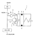
- FIG. 2 is a schematic diagram showing a simulator in a normal state.
- the normal state is a state in which the interlocking braking and the braking by ABS are not performed, and the front wheel and the rear wheel are braked only by the operation of the brake lever 101 and the brake pedal 201 by the user.
- the front wheel side simulator 1 stores a main check valve (check valve) 7, a relief valve (relief valve) 8 provided in parallel to the main check valve 7, and brake fluid.
- a cylinder 2 serving as a liquid storage chamber, a piston 3 serving as an adjusting portion for adjusting the volume of the cylinder 2, and a main spring (spring) 6 for pushing the piston 3 toward the main check valve 7 side.
- the main check valve 7 has a valve body 7a and a flow path 7b.
- the valve body 7a closes by closing the flow path 7b in close contact with the end 7c of the flow path 7b communicating with the cylinder 2, and the front wheel liquid It is provided so as to prevent the flow of brake fluid from the pressure circuit 100 to the cylinder 2.
- the main check valve 7 is provided so that brake fluid can flow freely from the cylinder 2 side to the front wheel hydraulic circuit 100 side.
- the relief valve 8 includes a valve body 8a, a flow path 8b, and a relief spring 8d, and the valve body 8a is in close contact with the end 8c of the flow path 8b communicating with the front wheel hydraulic circuit 100 to block the flow path 8b. So as to prevent the flow of brake fluid from the cylinder 2 to the front wheel hydraulic circuit 100. Further, the relief valve 8 is configured such that when the pressure that pushes the valve body 8a toward the cylinder 2 by the hydraulic pressure in the front wheel hydraulic circuit 100 becomes a certain value greater than the elastic force of the relief spring 8d, the valve body 8a Is pushed so that the brake fluid flows from the front wheel hydraulic circuit 100 to the cylinder 2.
- the relief valve 8 opens even when the front wheel side master cylinder 103 is actuated by the user operating the brake lever 101 during normal times when the front and rear wheels are not linked or during linked braking. Do not speak.
- the relief valve 8 is opened by the discharge pressure of the hydraulic pumps 119 and 219 when the ABS is operated. That is, the relief spring 8d of the relief valve 8 does not open only when the front wheel master cylinder 103 is operated, but opens during the antilock brake control in which the ABS is operated regardless of whether or not the interlock braking is performed. It has such an elastic force.
- the burden added to the pressure sensor provided in the hydraulic circuit 100,200 can be reduced. For this reason, the pressure-resistant intensity
- the internal space of the cylinder 2 is in fluid communication with the front wheel hydraulic circuit 100 via the main check valve 7 and the relief valve 8.
- the piston 3 is provided so that it can slide back and forth within the cylinder 2. In the simulator 1, the piston 3 slides in the cylinder 2 to adjust the volume of the cylinder 2. The piston 3 decreases the volume of the cylinder 2 as it approaches the main check valve 7 and increases the volume of the cylinder 2 as it moves away from the main check valve 7.
- the piston 3 is hermetically sealed with the liquid storage chamber 2 by winding an O (O) ring 4.
- the piston 3 is provided with a rod 5 that passes through the flow path 7b of the main check valve 7 and hits the valve body 7a.
- the rod 5 is provided so that the valve body 7a is pushed into the front wheel hydraulic circuit 100 side to be separated from the flow path 7b and the main check valve 7 is opened.
- the rod 5 is longer than the flow path 7b of the main check valve 7 and has an outer diameter smaller than the inner diameter of the flow path 7b.
- the main spring 6 is provided in the cylinder 2 on the back side of the surface of the piston 3 on which the rod 5 is provided.
- the main spring 6 does not hit the piston 3 when the piston 3 moves to a position where the main check valve 7 opens. That is, the main spring 6 does not push the piston 3 into the flow path 7b when the rod 5 is in contact with the valve body 7a of the main check valve 7.
- the piston 3 is located at a position where the rod 5 does not hit the valve body 7a of the main check valve 7, the main spring 6 comes into contact with the piston 3 and is pushed into the flow path 7b side of the main check valve 7. ing.
- the simulator 1 in the normal state has the piston 3 in the initial position, the piston 3 is not affected by the elastic force of the main spring 6, and the rod 5 of the piston 3 has a check valve. 7 is not pushed out, the main check valve 7 maintains the closed state.
- the elastic force of the relief spring 8d is stronger than the force of pushing the valve body 8a due to the increase of the hydraulic pressure of the hydraulic pressure circuit 100, 200 by the user's operation of the brake lever 101 or the brake pedal 201.
- the valve is closed.
- the simulator 1 stores brake fluid between the piston 3 of the cylinder 2 and the check valve 7 in a normal state.
- the simulator 1 does not change the hydraulic rigidity of the front wheel hydraulic circuit 100 when the main check valve 7 and the relief valve 8 are closed. As a result, the simulator 1 causes the hydraulic pressure of the raised front wheel hydraulic circuit 100 to increase in the cylinder 2 when the user operates the brake lever 101 in a state where braking of the front wheels and braking of the rear wheels are not linked. It is supposed not to run away.
- FIG. 3 is a schematic diagram showing the simulator during interlock braking.
- the front wheel hydraulic pump 119 When the front wheel brakes in conjunction with the rear wheel, the front wheel hydraulic pump 119 operates.
- the main check valve 7 is opened by the valve body 7a being drawn toward the front wheel hydraulic circuit 100 by the negative pressure generated on the suction side of the front wheel hydraulic pump 119.
- the piston 3 is in the front wheel hydraulic circuit 100.
- the cylinder 2 moves in the direction of expanding the volume.
- the valve element 7a does not come into close contact with the flow path 7b until the rod 5 is completely accommodated in the flow path 7b.
- the main check valve 7 maintains the valve open state until the piston 3 moves in a direction in which the volume of the cylinder 2 is expanded so that the rod 5 is completely accommodated in the flow path 7b.
- the simulator 1 expands the volume of the cylinder 2 so that the hydraulic pressure of the hydraulic circuit 100 is not increased even when the hydraulic pressure of the front wheel hydraulic circuit 100 is increased by interlocking braking.
- the feeling of the brake lever 101 can be reproduced in a pseudo manner. That is, the simulator 1 is provided with the cylinder 2 having a size sufficient to reproduce the so-called “play” in the non-linked braking state, which is caused by the hydraulic pressure escaping when the front wheel side master cylinder 103 is operated. .
- the piston 3 is moved from the wheel cylinder of the front wheel caliper 115 after the front wheel braking is finished.
- the volume of the cylinder 2 is increased by the hydraulic pressure when the brake fluid flows into the circuit 100.
- the piston 3 always returns to the initial position after the front wheel is braked in conjunction with the braking of the rear wheel, closes the main check valve 7 and is not affected by the elastic force of the main spring 6.
- FIG. 4 is a schematic diagram showing a simulator during ABS operation.
- the front wheel side switching valve 107 is opened, the front wheel side suction valve 109 is closed, and the front wheel side hydraulic pump 119 is operating.
- the brake fluid is discharged from the front-wheel hydraulic pump 119, and the hydraulic pressure of the brake fluid in the front-wheel hydraulic circuit 100 including the vicinity of the main check valve 7 and the relief valve 8 of the simulator 1 increases.
- the valve body 8a moves to the cylinder 2 side and the relief valve 8 is opened.
- the valve opening pressure of the relief valve 8 is desirably adjusted in accordance with the hydraulic pressure of the hydraulic circuit 100 when the wheel is locked.
- the pressure applied to the relief valve 8 is 50 bar (bar) or more. When it becomes, the relief valve 8 opens.
- the simulator 1 opens the relief valve 8 in the ABS operation state, so that the brake fluid flows into the cylinder 2 and pushes the piston 3 away from the relief valve 8. Thereby, the so-called damper effect of absorbing the pulsation of the hydraulic pressure of the brake fluid intermittently discharged from the front wheel side hydraulic pump 119 by expanding the volume of the cylinder 2 can be given to the front wheel hydraulic circuit 100.
- the brake control system 400 includes a main check valve 7 that prevents inflow of brake fluid from the hydraulic circuits 100 and 200 into the cylinder 2, and a valve open state when the main check valve 7 is opened. And a piston 3 having a rod 2 for maintenance.
- the volume of the cylinder 2 can be maximized when the interlock braking is not performed so that the user does not feel insufficient rigidity at the time of the brake operation.
- the volume of the cylinder 2 is expanded in accordance with the operation of the master cylinders 103 and 203, and a state in which the hydraulic pressure of the hydraulic circuit 100 is not increased can be simulated. For this reason, the brake control system 400 can simplify the structure for preventing the feeling of operation of the brake from being hardened during the interlocking braking of the brake.
- the brake control system 400 reliefs the relief valve 8 and the piston 3 that allow the brake fluid to flow into the cylinder 2 from the hydraulic circuits 100 and 200 only when a pressure equal to or greater than a certain value is applied.
- the main spring 6 for pushing back to the valve 8 side is provided, and the piston 3 can expand the volume of the cylinder 2 from the initial position.
- the relief valve 8 is not opened in the normal state and the interlocked braking state, so that it is possible to prevent the user from feeling insufficient rigidity during the brake operation and in the hydraulic circuits 100 and 200 during the ABS operation.
- the pulsation of the generated hydraulic pressure can be reduced.
- the pressure resistance of the pressure sensors 111 and 211 on the master cylinders 103 and 203 side can be set to a pressure resistance with respect to a pressure comparable to the pressure at which the relief valve 8 opens.
- the relief valve 8 is used as the relief valve, but the present invention is not limited to this. If the valve does not open in the normal state and the interlocked braking state, for example, it is possible to arbitrarily set the pressure at which the relief valve opens using the normally closed control valve, and it can be applied to various vehicle types by simply setting the valve opening pressure. The control performance may be improved.
- the brake control system 400 is mounted on a two-wheeled vehicle, but is not limited thereto. If the wheels are braked in conjunction with each other, the brake control system may be mounted on, for example, a three-wheeled vehicle or a four-wheeled vehicle.
Landscapes
- Engineering & Computer Science (AREA)
- Transportation (AREA)
- Mechanical Engineering (AREA)
- Physics & Mathematics (AREA)
- Fluid Mechanics (AREA)
- Regulating Braking Force (AREA)
Abstract
本発明は、ブレーキの連動制動時にブレーキの操作感が固くなるのを防ぐための構造を簡素化することができるブレーキ制御システムを提供することを目的とする。 第1の車輪の制動に連動して、ポンプを作動させることにより第2の車輪を連動制動可能なブレーキ制御システムにおいて、前記ポンプの吸込側と前記第2の車輪を制動させるためのマスタシリンダとの間の液圧回路100,200に逆止弁7を介して接続され、連動制動中に前記マスタシリンダが作動したときに前記液圧回路100,200のブレーキ液を貯留する貯液部1を備え、前記貯液部1は、前記ブレーキ液が貯留される貯液室2と、前記貯液室2の容積を調節するピストン3とを有し、前記逆止弁7は、前記貯液室2に連通する流路7bを塞ぐように弁体7aが密着したときに、前記液圧回路100,200から前記貯液室2への流体の流れを防止するように設けられ、前記ピストン3は、前記流路7bを貫通して前記弁体7aに当たり、前記弁体7aを前記流路7bから離間させるためのロッド5を設けた。
Description
本発明は、第1の車輪の制動に連動して、ポンプを作動させることにより第2の車輪を連動制動可能なブレーキ制御システムに関する。
従来、第1の車輪の制動に連動して、ポンプを作動させることにより第2の車輪を連動制動可能なブレーキ制御システムが知られている。この種のブレーキ制御システムでは、第2の車輪が連動制動しているときに、ポンプの作動により第2の車輪の液圧回路の液圧がポンプとホイールシリンダとの間で高くなってしまう。この状態で使用者がブレーキ操作を行うと、液圧回路の液圧が高いためブレーキの操作感が固く、使用者が違和感を覚えてしまうことがあった。このような問題を解消すべく、連動により第2の車輪の液圧回路の液圧が上昇しているときであっても、液圧回路の液圧が上昇していない状態を疑似的に再現するシミュレータを備えたブレーキ制御システムが提案されている(例えば、特許文献1参照)。
しかしながら、上記従来のブレーキ制御システムでは、シミュレータにシミュレータ弁、逆止弁、及びシミュレータチャンバを備え、シミュレータチャンバ内にはピストンとばねとが用いられており、部品点数が多くて構成が複雑になっていた。また、このようなブレーキ制御システムでは、シミュレータ弁の開閉を制御する必要があり、制御が複雑になっていた。
本発明の目的は、上述した従来の技術が有する課題を解消し、ブレーキの連動制動時にブレーキの操作感が固くなるのを防ぐための構造を簡素化することができるブレーキ制御システムを提供することにある。
本発明は、第1の車輪の制動に連動して、ポンプを作動させることにより第2の車輪を連動制動可能なブレーキ制御システムにおいて、前記ポンプの吸込側と前記第2の車輪を制動させるためのマスタシリンダとの間の液圧回路に逆止弁を介して接続され、連動制動中に前記マスタシリンダが作動したときに前記液圧回路のブレーキ液を貯留する貯液部を備え、前記貯液部は、前記ブレーキ液が貯留される貯液室と、前記貯液室の容積を調節するピストンとを有し、前記逆止弁は、前記貯液室に連通する流路を塞ぐように弁体が密着したときに、前記液圧回路から前記貯液室への流体の流れを防止するように設けられ、前記ピストンは、前記流路を貫通して前記弁体に当たり、前記弁体を前記流路から離間させるためのロッドが設けられたことを特徴とする。
この場合において、前記ロッドは、前記流路よりも長くてもよい。前記貯液部は、前記逆止弁に並列に設けられた逃し弁を介して、前記ポンプの吸込側と前記マスタシリンダとの間の前記液圧回路に接続されていてもよい。アンチロックブレーキ制御可能に設けられ、前記逃し弁は、前記アンチロックブレーキ制御中に開弁して前記液圧回路と前記シリンダとを連通させてもよい。前記逃し弁は、前記マスタシリンダの作動で開弁しなくてもよい。前記貯液部は、前記ピストンを前記流路側に押し込むためのばねを備えていてもよい。前記ばねは、前記ロッドが前記弁体に当たっているときに前記ピストンを前記流路側に押し込まなくてもよい。前記ピストンは、外周にOリングが巻き回されていてもよい。前記貯液室は、シリンダであってもよい。
本発明によると、ブレーキの連動制動時にブレーキの操作感が固くなるのを防ぐための構造を簡素化することができる。
以下、図面を参照して、本発明の好適な実施の形態について説明する。
図1は、本実施形態に係るブレーキ制御システムの液圧回路を示す回路図である。このブレーキ制御システム400は、自動二輪車に搭載され、前輪液圧回路100と、後輪液圧回路200と、前輪液圧回路100及び後輪液圧回路200の各液圧ポンプ119,219を駆動するDCモータ300とを備えている。液圧回路100,200は、ブレーキ液で満たされている。なお、図中一点鎖線で囲われた領域は1つのユニットに組み込まれていることを示している。
前輪液圧回路100は、運転者の右手で操作されるブレーキレバー101と、ブレーキレバー101が操作されると前輪液圧回路100を加圧する前輪側マスタシリンダ103と、前輪側マスタシリンダ103に接続された前輪側マスタシリンダ用リザーバ105と、管路104を介して前輪側マスタシリンダ103に接続された前輪側切替弁107と、管路104を介して前輪側マスタシリンダ103に接続された前輪側吸入弁109とを備えている。なお、管路104と前輪側切替弁107との接続部、及び管路104と前輪側吸入弁109との接続部には、それぞれフィルタが設けられている。さらに、管路104には圧力センサ111が設けられ、圧力センサ111は、前輪側マスタシリンダ103と前輪側切替弁107及び前輪側吸入弁109との間の圧力を検知して、電子制御ユニットであるECUに検知結果に基づく信号を送信するように設けられている。
前輪側込め弁113は、管路104に接続されている。前輪側込め弁113と管路104との接続部にも、フィルタが設けられている。前輪側込め弁113は、管路114を介して前輪側キャリパ115のホイールシリンダに接続されている。
前輪ブレーキは、前輪液圧回路100によって作動される。前輪ブレーキは、前輪側キャリパ115を含んでいる。
前輪側キャリパ115は、上述のように前輪側込め弁113と管路114とを介して接続されている。
管路106には、前輪側液圧ポンプ119の吐出側が絞りを介して接続されている。前輪側液圧ポンプ119の吸込側は、フィルタを介して管路120に接続されている。前輪側液圧ポンプ119は、DCモータ300により駆動される。また、管路120には、前輪側逆止弁121の一端が接続されている。さらに、管路120には、前輪側吸入弁109の吐出ポートが接続されている。また、前輪側逆止弁121の他端は、管路122に接続されている。前輪側逆止弁121は、管路120から管路122への逆流を防止するように配置されている。
また、管路122には、前輪側弛め弁123の吐出ポートが接続されている。さらに、管路122には、前輪側逆止弁121と前輪側弛め弁123との間に、前輪側アキュムレータ125が接続されている。
前輪側キャリパ115には、管路114を介して前輪側弛め弁123の流入ポートに接続されている。前輪側弛め弁123の流出ポートは、管路122に接続されている。また、前輪側弛め弁123の流入ポートと管路114との接続部には、フィルタが設けられている。管路114には、圧力センサ127が設けられており、圧力センサ127は、管路114内の圧力を測定して、ECUに圧力信号を送信する。
次に、図1を用いて後輪液圧回路200の構成を説明する。後輪液圧回路200は、運転者の右足で操作されるブレーキペダル201と、ブレーキペダル201が操作されると後輪液圧回路200を加圧する後輪側マスタシリンダ203と、後輪側マスタシリンダ203に接続された後輪側マスタシリンダ用リザーバ205と、管路204を介して後輪側マスタシリンダ203に接続された後輪側切替弁207と、管路204を介して後輪側マスタシリンダ203に接続された後輪側吸入弁209とを備える。なお、管路204と後輪側切替弁207との接続部、及び管路204と後輪側吸入弁209との接続部には、それぞれフィルタが設けられている。さらに、管路204には圧力センサ211が設けられ、圧力センサ211は、後輪側マスタシリンダ203と後輪側切替弁207及び後輪側吸入弁209との間の圧力を検知して、ECUに検知結果に基づく信号を送信する。
また、後輪側込め弁213は、後輪側切替弁207及び管路206を介して接続されている。後輪側切替弁207や後輪側込め弁213と管路206との接続部にも、それぞれフィルタが設けられている。後輪側込め弁213は、管路214を介して後輪側キャリパ215のホイールシリンダに接続されている。後輪ブレーキは、後輪側キャリパ215から構成される。そして、後輪側キャリパ215は、上述のように後輪側込め弁213及び管路214を介して接続されている。
一方、管路206には、後輪側液圧ポンプ219の吐出側が絞りを介して接続されている。後輪側液圧ポンプ219の吸込側は、フィルタを介して管路220に接続されている。後輪側液圧ポンプ219は、DCモータ300により駆動される。また、管路220には、後輪側逆止弁221の一端が接続されている。さらに、管路220には、後輪側吸入弁209の吐出ポートが接続されている。また、後輪側逆止弁221の他端は、管路222に接続されている。後輪側逆止弁221は、管路220から管路222への逆流を防止するように配置されている。
また、管路222には、後輪側弛め弁223の吐出ポートが接続されている。さらに、管路222には、後輪側逆止弁221と後輪側弛め弁223との間に、後輪側アキュムレータ225が接続されている。
後輪側キャリパ215は、管路214を介して後輪側弛め弁223の流入ポートに接続されている。後輪側弛め弁223の流出ポートは、管路222に接続されている。また、後輪側弛め弁223の流出ポートと管路214と接続部には、フィルタが設けられている。管路214には、圧力センサ227が設けられており、圧力センサ227は、管路214内の圧力を測定して、ECUに圧力信号を送信する。
ECUは、圧力信号、速度信号に基づき、所定の条件に従って、DCモータ300、前輪側切替弁107、前輪側吸入弁109、前輪側込め弁113、及び前輪側弛め弁123のそれぞれを作動する。さらに、ECUは、圧力信号、速度信号に基づき、所定の条件に従って、後輪側切替弁207、後輪側吸入弁209、後輪側込め弁213、及び後輪側弛め弁223のそれぞれを作動する。なお、各弁はソレノイドを備えた電磁弁であり、ECUによって通電されて開閉状態が切り換えられる。
さらに、ブレーキング時に、前輪速度センサや後輪速度センサからの回転速度信号をECUが受けて車輪のロックを検知した場合に、ECUは、ABS(アンチロックブレーキ制御システム)を作動させて、各液圧ポンプを作動し、各弁を開閉して、制動力を制御して車輪のロックを防止する。
本実施形態に係るブレーキ制御システム400は、使用者が前輪及び後輪の一方を制動させたときに他方も制動させることが可能に設けられている。
前輪のブレーキを制動させるべく使用者がブレーキレバー101のみを操作すると、前輪液圧回路100内のブレーキ液が加圧される。ECUは、圧力センサ111により前輪液圧回路100が加圧されたことを検出すると、後輪側吸入弁209を開くとともに、後輪側切替弁207を閉じる。また、ECUは、DCモータ300を駆動して後輪側液圧ポンプ219を作動させる。このとき、後輪側弛め弁223は閉じており、後輪側液圧ポンプ219は、後輪側液圧ポンプ219の吸込側と連通している後輪側マスタシリンダ203からブレーキ液を吸引する。後輪側液圧ポンプ219は、吸引したブレーキ液を吐出側から管路206内に吐出して後輪側キャリパ215にブレーキ液を供給し、後輪を制動させる。
一方、後輪のブレーキを制動させるべく使用者がブレーキペダル201のみを操作すると、後輪液圧回路200内のブレーキ液が加圧される。ECUは、圧力センサ211により後輪液圧回路200が加圧されたことを検出すると、前輪側吸入弁109を開くとともに、前輪側切替弁107を閉じる。また、ECUは、DCモータ300を駆動して前輪側液圧ポンプ119を作動させる。このとき、前輪側弛め弁123は閉じており、前輪側液圧ポンプ119は、前輪側液圧ポンプ119の吸込側と連通している前輪側マスタシリンダ103からブレーキ液を吸引する。前輪側液圧ポンプ119は、吸引したブレーキ液を吐出側から管路106内に吐出して前輪側キャリパ115にブレーキ液を供給し、前輪を制動させる。
ブレーキ制御システム400は、前輪側マスタシリンダ103と前輪側切替弁107及び前輪側吸入弁109との間にブレーキレバー101の操作性を所定のフィーリングにするためのシミュレータ(貯液部)1を備えている。一方、ブレーキ制御システム400は、後輪側マスタシリンダ203と後輪側切替弁207及び後輪側吸入弁209との間に、ブレーキペダル201の操作性を所定のフィーリングにするためのシミュレータ(貯液部)1を備えている。
前輪側のシミュレータ1は、後輪の制動に連動して前輪が制動するときに、前輪側吸入弁109が開いて前輪側切替弁107が閉じた状態で、前輪側液圧ポンプ119の吸込側と前輪側マスタシリンダ103との間の前輪液圧回路100上に流体的に連通して設けられている。前輪側のシミュレータ1は、前輪が後輪の制動に連動して制動している状態で、使用者がブレーキレバー101の操作により前輪側マスタシリンダ103を作動させたときに前輪液圧回路100のブレーキ液の一部を貯留できるようになっている。
後輪側のシミュレータ1は、前輪の制動に連動して後輪が制動するときに、後輪側吸入弁209が開いて後輪側切替弁207が閉じた状態で、後輪側液圧ポンプ219の吸込側と後輪側マスタシリンダ203との間の後輪液圧回路200上に流体的に連通して設けられている。後輪側のシミュレータ1は、後輪が前輪の制動に連動して制動している状態で、使用者がブレーキペダル201の操作により後輪側マスタシリンダ203を作動させたときに後輪液圧回路200のブレーキ液を貯留できるようになっている。
以下、シミュレータ1について説明する。なお、本実施形態におけるシミュレータ1は、前輪側と後輪側とで共通のものを使用しており、使用者がブレーキレバー101を操作したのかブレーキペダル201を操作したのかのみ異なるため、以下前輪側のシミュレータ1のみについて説明する。
図2は、通常状態のシミュレータを示す模式図である。なお、通常状態とは、連動制動及びABSによる制動を行っていない状態であって、使用者のブレーキレバー101やブレーキペダル201の操作のみによって前輪や後輪が制動する状態とする。
前輪側のシミュレータ1は、図2に示すように、メインチェックバルブ(逆止弁)7と、このメインチェックバルブ7に並列に設けられたリリーフ弁(逃し弁)8と、ブレーキ液が貯留される貯液室であるシリンダ2と、このシリンダ2の容積を調節する調節部であるピストン3と、ピストン3をメインチェックバルブ7側に押し込むためのメインスプリング(ばね)6を備えている。
メインチェックバルブ7は、弁体7a、及び流路7bを有し、弁体7aがシリンダ2に連通する流路7bの端部7cに密着して流路7bを塞ぐことにより閉じて、前輪液圧回路100からシリンダ2へのブレーキ液の流れを防止するように設けられている。また、メインチェックバルブ7は、ブレーキ液がシリンダ2側から前輪液圧回路100側へ流通自在に設けられている。
リリーフ弁8は、弁体8a、流路8b、及びリリーフスプリング8dを有し、弁体8aが前輪液圧回路100に連通する流路8bの端部8cに密着して流路8bを塞ぐことにより閉じてシリンダ2から前輪液圧回路100へのブレーキ液の流れを防止するように設けられている。また、リリーフ弁8は、前輪液圧回路100内の液圧によって弁体8aをシリンダ2側に押す圧力が、リリーフスプリング8dの弾性力よりも大きな一定値以上になったときに、弁体8aが押されてブレーキ液が前輪液圧回路100からシリンダ2へ流れるように設けられている。具体的には、リリーフ弁8は、前輪及び後輪が連動制動していない通常時や連動制動中に、使用者がブレーキレバー101を操作したことにより前輪側マスタシリンダ103が作動しても開弁しないようになっている。一方、リリーフ弁8は、ABSが作動したときに液圧ポンプ119,219の吐出圧により開弁するようになっている。すなわち、リリーフ弁8のリリーフスプリング8dは、前輪側マスタシリンダ103が作動しただけでは開弁しないが、連動制動しているか否かに関わらず、ABSが作動したアンチロックブレーキ制御中に開弁するような弾性力になっている。これにより、液圧回路100,200に作用する液圧の上昇を抑えることができるので、液圧回路100,200に設けられた圧力センサに加わる負担を軽減することができる。このため、圧力センサに求められる耐圧強度を下げることができ、より高性能な圧力センサを採用することができる。
シリンダ2は、内部空間がメインチェックバルブ7及びリリーフ弁8を介して前輪液圧回路100と流体的に連通している。
ピストン3は、シリンダ2内をスライドして往復できるように設けられている。シミュレータ1は、ピストン3がシリンダ2内をスライドしてシリンダ2の容積を調節する。ピストン3は、メインチェックバルブ7に近づくほどシリンダ2の容積を縮小し、メインチェックバルブ7から離れるほどシリンダ2の容積を拡大するようになっている。ピストン3は、O(オー)リング4が巻き回されていることにより、貯液室2との間が密封されている。ピストン3は、メインチェックバルブ7の流路7bを貫通して弁体7aに当たるロッド5が設けられている。このロッド5は、弁体7aを前輪液圧回路100側に押し込んで流路7bから離間させ、メインチェックバルブ7を開弁させるように設けられている。ロッド5は、メインチェックバルブ7の流路7bよりも長く、かつ、その外径が流路7bの内径よりも小さく形成されている。
メインスプリング6は、シリンダ2内であって、ピストン3におけるロッド5が設けられた面の背面側に設けられている。メインスプリング6は、メインチェックバルブ7が開弁する位置にピストン3が移動したときはピストン3に当たらないようになっている。すなわち、メインスプリング6は、ロッド5がメインチェックバルブ7の弁体7aに当たっているときにピストン3を流路7b側に押し込まないようになっている。一方、メインスプリング6は、メインチェックバルブ7の弁体7aにロッド5が当たらない位置にピストン3が位置しているときは、ピストン3に当たってメインチェックバルブ7の流路7b側に押し込むようになっている。
通常状態のシミュレータ1は、図2に示すように、ピストン3が初期位置にあり、ピストン3がメインスプリング6による弾性力の影響を受けておらず、また、ピストン3のロッド5が逆止弁7の弁体7aを押し出さないため、メインチェックバルブ7は、閉弁状態を維持している。リリーフ弁8は、使用者のブレーキレバー101やブレーキペダル201の操作による液圧回路100,200の液圧の上昇により弁体8aを押す力よりもリリーフスプリング8dの弾性力の方が強いため、閉弁状態を維持している。シミュレータ1は、通常状態において、ブレーキ液をシリンダ2のピストン3と逆止弁7との間に貯留している。
シミュレータ1は、メインチェックバルブ7及びリリーフ弁8を閉じた状態では、前輪液圧回路100側に対して液圧剛性の変化を与えない。これにより、シミュレータ1は、前輪の制動と後輪の制動とが連動していない状態で、使用者がブレーキレバー101を操作したときに、上昇した前輪液圧回路100の液圧がシリンダ2内に逃げないようになっている。
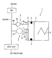
図3は、連動制動中のシミュレータを示す模式図である。
前輪が後輪に連動して制動すると、前輪側液圧ポンプ119が作動する。メインチェックバルブ7は、前輪側液圧ポンプ119の吸込側に生じた負圧により、弁体7aが前輪液圧回路100側に引き寄せられて開弁する。
メインチェックバルブ7が開弁すると、前輪側液圧ポンプ119の吸込側に生じた負圧により、図3に示すように、ピストン3もメインチェックバルブ7側に引き寄せられて、シリンダ2の容積を縮小させるようになっている。このとき、ピストン3は、シリンダ2内に貯留していたブレーキ液を前輪液圧回路100側に吐出するようになっている。
一方、ピストン3は、前輪が後輪の制動に連動して制動している状態で、使用者がブレーキレバー101の操作により前輪側マスタシリンダ103を作動させたときに、前輪液圧回路100内の液圧が上昇することにより、シリンダ2の容積を拡大する方向に移動する。このとき、ピストン3にはロッド5が設けられていることにより、ロッド5が流路7b内に完全に収まるまで弁体7aは流路7bと密着しない。これにより、メインチェックバルブ7は、ロッド5が流路7b内に完全に収まる位ピストン3がシリンダ2の容積を拡大する方向に移動するまで開弁状態を維持する。シミュレータ1は、シリンダ2の容積を拡大することにより、連動制動により前輪液圧回路100の液圧が上昇しているときであっても、液圧回路100の液圧が上昇していない状態のブレーキレバー101のフィーリングを疑似的に再現することができる。すなわち、シミュレータ1は、前輪側マスタシリンダ103が作動したときに液圧が逃げることにより生じる、非連動制動状態のいわゆる「遊び」を再現するのに十分な大きさでシリンダ2が設けられている。
なお、ピストン3は、前輪が連動制動している状態で使用者がブレーキレバー101の操作を行わなかった場合には、前輪の制動が終了したのちに前輪側キャリパ115のホイールシリンダから前輪液圧回路100にブレーキ液が流入したときの液圧で、シリンダ2の容積を拡大するようになっている。
ピストン3は、前輪が後輪の制動に連動して制動した後は、常に、初期位置に戻り、メインチェックバルブ7を閉弁するとともにメインスプリング6の弾性力による影響を受けない状態になる。
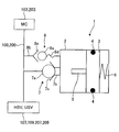
図4は、ABS作動中のシミュレータを示す模式図である。
通常状態または連動制動状態に関わらず、ABS作動状態では、前輪側切替弁107は開弁し、前輪側吸入弁109は閉弁し、前輪側液圧ポンプ119が作動している。これにより、前輪側液圧ポンプ119からブレーキ液が吐出されることにより、シミュレータ1のメインチェックバルブ7及びリリーフ弁8近傍を含む前輪液圧回路100内のブレーキ液の液圧が上昇する。このとき、リリーフ弁8に付与される圧力が一定値以上になると、弁体8aがシリンダ2側に移動してリリーフ弁8が開弁する。なお、リリーフ弁8の開弁圧は、車輪がロックするときの液圧回路100の液圧に合わせて調整されるのが望ましく、例えば、リリーフ弁8に付与される圧力が50bar(バール)以上になったらリリーフ弁8が開弁する。
シミュレータ1は、ABS作動状態にリリーフ弁8が開弁することにより、ブレーキ液がシリンダ2内に流入してピストン3をリリーフ弁8から離れる方向に押し込む。これにより、シリンダ2の容積を拡大して前輪側液圧ポンプ119から断続的に吐出されたブレーキ液の液圧の脈動を吸収するいわゆるダンパ効果を前輪液圧回路100に与えることができる。
本実施形態では、ブレーキ制御システム400は、液圧回路100,200からシリンダ2内へのブレーキ液の流入を防止するメインチェックバルブ7と、メインチェックバルブ7が開弁したときに開弁状態を維持するためのロッド2を有するピストン3とを備えている。これにより、連動制動していないときは、シリンダ2の容積を最大にして、使用者にブレーキ操作時の剛性不足を感じさせないようにすることができ、連動制動しているときは、シリンダ2の容積を最小にした後に、マスタシリンダ103,203の作動に応じてシリンダ2の容積を拡大し、液圧回路100の液圧が上昇していない状態を疑似的に再現することができる。このため、ブレーキ制御システム400は、ブレーキの連動制動時にブレーキの操作感が固くなるのを防ぐための構造を簡素化することができる。
また、本実施形態では、ブレーキ制御システム400は、一定値以上の圧力が付与されたときのみに液圧回路100,200からシリンダ2内へブレーキ液を流入させるリリーフ弁8と、ピストン3をリリーフ弁8側に押し戻すためのメインスプリング6とを有し、ピストン3は初期位置よりもシリンダ2の容積を拡大できるようになっている。これにより、通常状態及び連動制動状態ではリリーフ弁8を開弁しないため、使用者にブレーキ操作時の剛性不足を感じさせないようにすることができるとともに、ABS作動時に液圧回路100,200内で生じる液圧の脈動を軽減することができる。また、一定値以上の圧力が生じたときにリリーフするため、液圧回路100,200内の構成部品の耐圧強度を低くすることができ、コスト低減や構造の簡素化をもたらすことができる。例えば、マスタシリンダ103,203側の圧力センサ111,211の耐圧強度をリリーフ弁8が開弁する圧力と同程度の圧力に対する耐圧強度にすることができる。
以上、実施形態に基づいて本発明を説明したが、本発明は、これに限定されるものではない。例えば、実施形態では、逃し弁としてリリーフ弁8を用いているが、これに限定されることはない。通常状態及び連動制動状態で開弁しなければ、例えば、ノーマルクローズコントロールバルブを用いてリリーフ弁が開弁する圧力を任意に設定可能にし、開弁圧を設定するだけで様々な車種に適用できるようにしたり、制御性能を向上させたりしてもよい。
また、実施形態では、ブレーキ制御システム400は、2輪車に搭載されているが、これに限定されることはない。車輪が連動して制動されれば、ブレーキ制御システムは、例えば、3輪車や4輪車等に搭載されていてもよい。
1 シミュレータ(貯液部)
2 シリンダ(貯液室)
3 ピストン
4 Oリング
5 ロッド
6 メインスプリング(ばね)
7 メインチェックバルブ(逆止弁)
7a 弁体
7b 流路
7c 端部
8 リリーフ弁(逃し弁)
8a 弁体
8b 流路
8c 端部
8d リリーフスプリング
100 前輪液圧回路
101 ブレーキレバー
103 前輪側マスタシリンダ
105 前輪側マスタシリンダ用リザーバ
104 管路
106 管路
107 前輪側切替弁
109 前輪側吸入弁
111 圧力センサ
113 前輪側込め弁
114 管路
115 前輪側キャリパ
119 前輪側液圧ポンプ
120 管路
121 前輪側逆止弁
122 管路
123 前輪側弛め弁
125 アキュムレータ
127 圧力センサ
129 前輪速度センサ
200 後輪液圧回路
201 ブレーキペダル
203 後輪側マスタシリンダ
204 管路
205 後輪側マスタシリンダ用リザーバ
207 後輪側切替弁
209 後輪側吸入弁
211 圧力センサ
213 後輪側込め弁
214 管路
215 後輪側キャリパ
219 後輪側液圧ポンプ
220 管路
221 後輪側逆止弁
222 管路
223 後輪側弛め弁
225 後輪側アキュムレータ
227 圧力センサ
229 後輪速度センサ
300 DCモータ
400 ブレーキ制御システム
2 シリンダ(貯液室)
3 ピストン
4 Oリング
5 ロッド
6 メインスプリング(ばね)
7 メインチェックバルブ(逆止弁)
7a 弁体
7b 流路
7c 端部
8 リリーフ弁(逃し弁)
8a 弁体
8b 流路
8c 端部
8d リリーフスプリング
100 前輪液圧回路
101 ブレーキレバー
103 前輪側マスタシリンダ
105 前輪側マスタシリンダ用リザーバ
104 管路
106 管路
107 前輪側切替弁
109 前輪側吸入弁
111 圧力センサ
113 前輪側込め弁
114 管路
115 前輪側キャリパ
119 前輪側液圧ポンプ
120 管路
121 前輪側逆止弁
122 管路
123 前輪側弛め弁
125 アキュムレータ
127 圧力センサ
129 前輪速度センサ
200 後輪液圧回路
201 ブレーキペダル
203 後輪側マスタシリンダ
204 管路
205 後輪側マスタシリンダ用リザーバ
207 後輪側切替弁
209 後輪側吸入弁
211 圧力センサ
213 後輪側込め弁
214 管路
215 後輪側キャリパ
219 後輪側液圧ポンプ
220 管路
221 後輪側逆止弁
222 管路
223 後輪側弛め弁
225 後輪側アキュムレータ
227 圧力センサ
229 後輪速度センサ
300 DCモータ
400 ブレーキ制御システム
Claims (9)
- 第1の車輪の制動に連動して、ポンプを作動させることにより第2の車輪を連動制動可能なブレーキ制御システムにおいて、
前記ポンプの吸込側と前記第2の車輪を制動させるためのマスタシリンダとの間の液圧回路に逆止弁を介して接続され、連動制動中に前記マスタシリンダが作動したときに前記液圧回路のブレーキ液を貯留する貯液部を備え、
前記貯液部は、前記ブレーキ液が貯留される貯液室と、前記貯液室の容積を調節するピストンとを有し、
前記逆止弁は、前記貯液室に連通する流路を塞ぐように弁体が密着したときに、前記液圧回路から前記貯液室への流体の流れを防止するように設けられ、
前記ピストンは、前記流路を貫通して前記弁体に当たり、前記弁体を前記流路から離間させるためのロッドが設けられたことを特徴とするブレーキ制御システム。 - 請求項1に記載のブレーキ制御システムにおいて、
前記ロッドは、前記流路よりも長いことを特徴とするブレーキ制御システム。 - 請求項1または2に記載のブレーキ制御システムにおいて、
前記貯液部は、前記逆止弁に並列に設けられた逃し弁を介して、前記ポンプの吸込側と前記マスタシリンダとの間の前記液圧回路に接続されたことを特徴とするブレーキ制御システム。 - 請求項3に記載のブレーキ制御システムにおいて、
アンチロックブレーキ制御可能に設けられ、前記逃し弁は、前記アンチロックブレーキ制御中に開弁して前記液圧回路と前記シリンダとを連通させることを特徴とするブレーキ制御システム。 - 請求項3または4に記載のブレーキ制御システムにおいて、
前記逃し弁は、前記マスタシリンダの作動で開弁しないことを特徴とするブレーキ制御システム。 - 請求項1乃至5のいずれか一項に記載のブレーキ制御システムにおいて、
前記貯液部は、前記ピストンを前記流路側に押し込むためのばねを備えたことを特徴とするブレーキ制御システム。 - 請求項6に記載のブレーキ制御システムにおいて、
前記ばねは、前記ロッドが前記弁体に当たっているときに前記ピストンを前記流路側に押し込まないことを特徴とするブレーキ制御システム。 - 請求項1乃至7のいずれか一項に記載のブレーキ制御システムにおいて、
前記ピストンは、外周にOリングが巻き回されたことを特徴とするブレーキ制御システム。 - 請求項1乃至8のいずれか一項に記載のブレーキ制御システムにおいて、
前記貯液室は、シリンダであることを特徴とするブレーキ制御システム。
Applications Claiming Priority (2)
| Application Number | Priority Date | Filing Date | Title |
|---|---|---|---|
| JP2011-235234 | 2011-10-26 | ||
| JP2011235234A JP2015003527A (ja) | 2011-10-26 | 2011-10-26 | ブレーキ制御システム |
Publications (1)
| Publication Number | Publication Date |
|---|---|
| WO2013061920A1 true WO2013061920A1 (ja) | 2013-05-02 |
Family
ID=48167752
Family Applications (1)
| Application Number | Title | Priority Date | Filing Date |
|---|---|---|---|
| PCT/JP2012/077230 Ceased WO2013061920A1 (ja) | 2011-10-26 | 2012-10-22 | ブレーキ制御システム |
Country Status (2)
| Country | Link |
|---|---|
| JP (1) | JP2015003527A (ja) |
| WO (1) | WO2013061920A1 (ja) |
Citations (3)
| Publication number | Priority date | Publication date | Assignee | Title |
|---|---|---|---|---|
| JP2002002464A (ja) * | 2000-06-26 | 2002-01-09 | Sumitomo Denko Brake Systems Kk | 電動車両用制動装置 |
| JP2007269213A (ja) * | 2006-03-31 | 2007-10-18 | Nissin Kogyo Co Ltd | 車両用ブレーキ液圧制御装置 |
| JP2012051455A (ja) * | 2010-09-01 | 2012-03-15 | Hitachi Automotive Systems Ltd | 液圧ブレーキ制御装置 |
-
2011
- 2011-10-26 JP JP2011235234A patent/JP2015003527A/ja active Pending
-
2012
- 2012-10-22 WO PCT/JP2012/077230 patent/WO2013061920A1/ja not_active Ceased
Patent Citations (3)
| Publication number | Priority date | Publication date | Assignee | Title |
|---|---|---|---|---|
| JP2002002464A (ja) * | 2000-06-26 | 2002-01-09 | Sumitomo Denko Brake Systems Kk | 電動車両用制動装置 |
| JP2007269213A (ja) * | 2006-03-31 | 2007-10-18 | Nissin Kogyo Co Ltd | 車両用ブレーキ液圧制御装置 |
| JP2012051455A (ja) * | 2010-09-01 | 2012-03-15 | Hitachi Automotive Systems Ltd | 液圧ブレーキ制御装置 |
Also Published As
| Publication number | Publication date |
|---|---|
| JP2015003527A (ja) | 2015-01-08 |
Similar Documents
| Publication | Publication Date | Title |
|---|---|---|
| JP6197098B2 (ja) | 車両のためのブレーキシステム | |
| JP5860800B2 (ja) | ブレーキ装置 | |
| JP5892706B2 (ja) | ブレーキ液圧発生装置 | |
| CN104395159B (zh) | 制动控制装置 | |
| CN102307760B (zh) | 制动装置 | |
| JP6063824B2 (ja) | ブレーキ制御装置 | |
| US10988123B2 (en) | Simulator valve and electronic brake system using the same | |
| KR20140122671A (ko) | 차량용 브레이크 시스템, 및 브레이크 시스템의 작동 방법 | |
| JP5080521B2 (ja) | ブレーキ装置 | |
| JP2011218839A (ja) | 車両用ブレーキ装置および車両用ブレーキ装置の制御方法 | |
| JP2013514933A (ja) | 油圧式車両ブレーキ装置 | |
| JP6446481B2 (ja) | 鞍乗型車両のブレーキ制御装置 | |
| JP2013540073A (ja) | 液圧ユニット | |
| JP6245696B2 (ja) | ブレーキ液圧発生装置 | |
| EP1693263A1 (en) | Electronically controlled hydraulic brake system | |
| JPS62203861A (ja) | スリツプ制御形ブレ−キシステム | |
| JP2014121959A (ja) | ストロークシミュレータ、及びブレーキ制御システム | |
| WO2013061920A1 (ja) | ブレーキ制御システム | |
| JP6159554B2 (ja) | ブレーキ液圧制御装置 | |
| JP6257273B2 (ja) | ブレーキ制御装置 | |
| JP2013107623A (ja) | ブレーキ制御システム | |
| JP6069063B2 (ja) | ブレーキ制御装置 | |
| JP4681572B2 (ja) | 車両用ブレーキ液圧制御装置 | |
| JP4728981B2 (ja) | シミュレータ及び車両用ブレーキ制御装置 | |
| JP5269607B2 (ja) | 自動二輪車ブレーキシステム |
Legal Events
| Date | Code | Title | Description |
|---|---|---|---|
| 121 | Ep: the epo has been informed by wipo that ep was designated in this application |
Ref document number: 12843019 Country of ref document: EP Kind code of ref document: A1 |
|
| NENP | Non-entry into the national phase |
Ref country code: DE |
|
| 122 | Ep: pct application non-entry in european phase |
Ref document number: 12843019 Country of ref document: EP Kind code of ref document: A1 |
|
| NENP | Non-entry into the national phase |
Ref country code: JP |