WO2013061917A1 - 伸縮性シートの製造方法 - Google Patents
伸縮性シートの製造方法 Download PDFInfo
- Publication number
- WO2013061917A1 WO2013061917A1 PCT/JP2012/077224 JP2012077224W WO2013061917A1 WO 2013061917 A1 WO2013061917 A1 WO 2013061917A1 JP 2012077224 W JP2012077224 W JP 2012077224W WO 2013061917 A1 WO2013061917 A1 WO 2013061917A1
- Authority
- WO
- WIPO (PCT)
- Prior art keywords
- adhesive
- pair
- belt
- sheets
- sheet
- Prior art date
- Legal status (The legal status is an assumption and is not a legal conclusion. Google has not performed a legal analysis and makes no representation as to the accuracy of the status listed.)
- Ceased
Links
- ASXTVMFJPFZJMW-UHFFFAOYSA-N CCC1C(C2)C2CC1 Chemical compound CCC1C(C2)C2CC1 ASXTVMFJPFZJMW-UHFFFAOYSA-N 0.000 description 1
Images

Classifications
-
- A—HUMAN NECESSITIES
- A61—MEDICAL OR VETERINARY SCIENCE; HYGIENE
- A61F—FILTERS IMPLANTABLE INTO BLOOD VESSELS; PROSTHESES; DEVICES PROVIDING PATENCY TO, OR PREVENTING COLLAPSING OF, TUBULAR STRUCTURES OF THE BODY, e.g. STENTS; ORTHOPAEDIC, NURSING OR CONTRACEPTIVE DEVICES; FOMENTATION; TREATMENT OR PROTECTION OF EYES OR EARS; BANDAGES, DRESSINGS OR ABSORBENT PADS; FIRST-AID KITS
- A61F13/00—Bandages or dressings; Absorbent pads
- A61F13/15—Absorbent pads, e.g. sanitary towels, swabs or tampons for external or internal application to the body; Supporting or fastening means therefor; Tampon applicators
- A61F13/15577—Apparatus or processes for manufacturing
- A61F13/15585—Apparatus or processes for manufacturing of babies' napkins, e.g. diapers
- A61F13/15593—Apparatus or processes for manufacturing of babies' napkins, e.g. diapers having elastic ribbons fixed thereto; Devices for applying the ribbons
- A61F13/15601—Apparatus or processes for manufacturing of babies' napkins, e.g. diapers having elastic ribbons fixed thereto; Devices for applying the ribbons the ribbons being applied transversely to the direction of the movement of the webs the diapers are being made of
-
- A—HUMAN NECESSITIES
- A61—MEDICAL OR VETERINARY SCIENCE; HYGIENE
- A61F—FILTERS IMPLANTABLE INTO BLOOD VESSELS; PROSTHESES; DEVICES PROVIDING PATENCY TO, OR PREVENTING COLLAPSING OF, TUBULAR STRUCTURES OF THE BODY, e.g. STENTS; ORTHOPAEDIC, NURSING OR CONTRACEPTIVE DEVICES; FOMENTATION; TREATMENT OR PROTECTION OF EYES OR EARS; BANDAGES, DRESSINGS OR ABSORBENT PADS; FIRST-AID KITS
- A61F13/00—Bandages or dressings; Absorbent pads
- A61F13/15—Absorbent pads, e.g. sanitary towels, swabs or tampons for external or internal application to the body; Supporting or fastening means therefor; Tampon applicators
- A61F13/15577—Apparatus or processes for manufacturing
- A61F13/15585—Apparatus or processes for manufacturing of babies' napkins, e.g. diapers
- A61F13/15593—Apparatus or processes for manufacturing of babies' napkins, e.g. diapers having elastic ribbons fixed thereto; Devices for applying the ribbons
-
- A—HUMAN NECESSITIES
- A61—MEDICAL OR VETERINARY SCIENCE; HYGIENE
- A61F—FILTERS IMPLANTABLE INTO BLOOD VESSELS; PROSTHESES; DEVICES PROVIDING PATENCY TO, OR PREVENTING COLLAPSING OF, TUBULAR STRUCTURES OF THE BODY, e.g. STENTS; ORTHOPAEDIC, NURSING OR CONTRACEPTIVE DEVICES; FOMENTATION; TREATMENT OR PROTECTION OF EYES OR EARS; BANDAGES, DRESSINGS OR ABSORBENT PADS; FIRST-AID KITS
- A61F13/00—Bandages or dressings; Absorbent pads
- A61F13/15—Absorbent pads, e.g. sanitary towels, swabs or tampons for external or internal application to the body; Supporting or fastening means therefor; Tampon applicators
- A61F13/45—Absorbent pads, e.g. sanitary towels, swabs or tampons for external or internal application to the body; Supporting or fastening means therefor; Tampon applicators characterised by the shape
- A61F13/49—Absorbent pads, e.g. sanitary towels, swabs or tampons for external or internal application to the body; Supporting or fastening means therefor; Tampon applicators characterised by the shape specially adapted to be worn around the waist, e.g. diapers, nappies
- A61F13/49007—Form-fitting, self-adjusting disposable diapers
- A61F13/49009—Form-fitting, self-adjusting disposable diapers with elastic means
- A61F13/49011—Form-fitting, self-adjusting disposable diapers with elastic means the elastic means is located at the waist region
-
- A—HUMAN NECESSITIES
- A61—MEDICAL OR VETERINARY SCIENCE; HYGIENE
- A61F—FILTERS IMPLANTABLE INTO BLOOD VESSELS; PROSTHESES; DEVICES PROVIDING PATENCY TO, OR PREVENTING COLLAPSING OF, TUBULAR STRUCTURES OF THE BODY, e.g. STENTS; ORTHOPAEDIC, NURSING OR CONTRACEPTIVE DEVICES; FOMENTATION; TREATMENT OR PROTECTION OF EYES OR EARS; BANDAGES, DRESSINGS OR ABSORBENT PADS; FIRST-AID KITS
- A61F13/00—Bandages or dressings; Absorbent pads
- A61F13/15—Absorbent pads, e.g. sanitary towels, swabs or tampons for external or internal application to the body; Supporting or fastening means therefor; Tampon applicators
- A61F13/56—Supporting or fastening means
- A61F13/5622—Supporting or fastening means specially adapted for diapers or the like
- A61F13/565—Supporting or fastening means specially adapted for diapers or the like pants type diaper
- A61F13/5655—Supporting or fastening means specially adapted for diapers or the like pants type diaper adjustable pants type diapers
-
- A—HUMAN NECESSITIES
- A61—MEDICAL OR VETERINARY SCIENCE; HYGIENE
- A61F—FILTERS IMPLANTABLE INTO BLOOD VESSELS; PROSTHESES; DEVICES PROVIDING PATENCY TO, OR PREVENTING COLLAPSING OF, TUBULAR STRUCTURES OF THE BODY, e.g. STENTS; ORTHOPAEDIC, NURSING OR CONTRACEPTIVE DEVICES; FOMENTATION; TREATMENT OR PROTECTION OF EYES OR EARS; BANDAGES, DRESSINGS OR ABSORBENT PADS; FIRST-AID KITS
- A61F13/00—Bandages or dressings; Absorbent pads
- A61F13/15—Absorbent pads, e.g. sanitary towels, swabs or tampons for external or internal application to the body; Supporting or fastening means therefor; Tampon applicators
- A61F13/15577—Apparatus or processes for manufacturing
- A61F2013/15821—Apparatus or processes for manufacturing characterized by the apparatus for manufacturing
- A61F2013/15861—Apparatus or processes for manufacturing characterized by the apparatus for manufacturing for bonding
- A61F2013/1591—Apparatus or processes for manufacturing characterized by the apparatus for manufacturing for bonding via adhesive
Definitions
- the present invention relates to a method for producing an elastic sheet.
- a substantially vertically long absorbent body provided with a top sheet, a back sheet, and an absorbent body disposed between both sheets, and a pair provided on both side edges along the longitudinal direction of the absorbent body.
- a fastening portion of a fastening tape fixed to an outer edge along the longitudinal direction of the main body of each of the pair of waist panels, and a non-skin-facing surface of the absorbent main body, 2.
- a so-called unfolded panel type disposable diaper that is adapted to be worn and worn by a wearer is known.
- a sheet-like member elastic sheet having elasticity is used from the viewpoint of wearability and the like.
- Patent Document 1 is configured as an unfolded panel-type disposable diaper using a stretchable sheet for a waist panel, and a plurality of thread-like elastic bodies are bonded and fixed between two sheets in an expanded state.
- a tape-type disposable diaper using an elastic sheet as a waist panel (fastening tape) is described.
- the two sheets are continuously formed from the upper end to the lower end of the fastening tape formed at a predetermined interval in the width direction (direction perpendicular to the longitudinal direction of the main body). Bonded by vertically striped bonded portions.
- Patent Document 1 as a method of manufacturing a waist panel (fastening tape) of Patent Document 1, an adhesive is applied to a sheet being transported in the length direction in a vertical stripe shape, and then the sheet is transported to a pair. After joining the thread-like elastic body that has been stretched by being wound around the belt in a spiral shape and pulled in a direction substantially perpendicular to the conveying direction of the sheet, another sheet is bonded to the sheet. It is described that the thread-like elastic bodies are joined so as to be sandwiched therebetween, and they are integrally pressed and integrated between a pair of rolls.
- the thread-like elastic body produced by cutting both ends of the thread-like elastic body wound around the conveyor belt in the stretched state at the time of manufacture. End portions (cut end portions) of the thread-like elastic body may be individually oriented in irregular directions due to shrinkage after the cut of the thread-like elastic body. May get worse.
- the present invention is an elastic sheet in which a thread-like elastic body is bonded and fixed in a state extending in a direction crossing the conveying direction of the belt-like sheet between a pair of belt-like sheets, and has a central joint portion in the center in the width direction. And it is related with the manufacturing method of the elastic sheet which manufactures the elastic sheet which has a pair of edge part junction part on both sides of this width direction center part continuously.
- the elastic thread winding means is used to wind the thread-like elastic body so that the thread-like elastic body is stretched in a direction intersecting the transport direction.
- the pair of band-like sheets after the process are joined to the thread-like elastic body conveyed by the conveying means, and the pair of band-like sheets sandwiching the thread-like elastic body are pressed together to form the stretchable sheet. Integration step to obtain.
- the bonding condition in the integration step between the pair of strip-shaped sheets is the adhesive for forming the central joint and the adhesive for forming the end joint. Different depending on the agent.
- the pair of belt-like sheets are introduced and pressed between the pair of rolls, and an adhesive for forming the central joint is added as the pair of rolls.
- an adhesive for forming the central joint is added as the pair of rolls.
- the pair of belt-like sheets are introduced and pressed between a pair of rolls, and the center joint portion is attached to one or both of the pair of belt-like sheets.
- the time from application of the forming adhesive to the pressurization of the adhesive between the pair of rolls, and the application of the adhesive for forming the end joints, the adhesive to the pair of rolls Different time between pressurization.
- the adhesive for the central joint portion or the adhesive for the end joint portion is cooled or heated to perform the integration step.
- the pair of belt-like sheets are pressed between a pair of rolls in a state where the two adhesives having different temperatures due to cooling or heating are interposed between the pair of belt-like sheets.
- the stretchable sheet in the present invention is preferably a stretchable sheet in which a thread-like elastic body is bonded and fixed in a state extending in a direction intersecting the transport direction of the strip-like sheet between a pair of strip-like sheets, and the center in the width direction thereof.
- the center portion has a central joint portion and a pair of end joint portions on both sides of the widthwise central portion.
- the present invention also provides an absorptive main body having an abdominal part located on the abdomen side of the wearer at the time of wearing, a dorsal part located on the dorsal side, and a crotch part located between the abdomen and back side parts And a pair of left and right waist panels connected to the left and right outer sides of the back side portion, and the waist panel is a disposable diaper using the elastic sheet obtained by the method for manufacturing the elastic sheet Is to provide.
- FIG. 1 is a plan view showing a waist panel and a deployable disposable diaper obtained by one embodiment of the present invention.
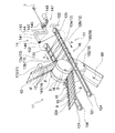
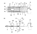
- FIG. 2 is a perspective view showing a schematic configuration of a stretchable sheet manufacturing apparatus suitably used for carrying out the manufacturing method of one embodiment (first embodiment) of the present invention.
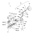
- FIG. 3 is a perspective view showing a configuration upstream of the rotary arm (elastic body winding means) of the apparatus shown in FIG.
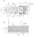
- FIG. 4A is a bird's-eye view of a part of the apparatus shown in FIG. 2, and
- FIG. 4B is a plan view showing an example of a stretchable sheet manufactured by the apparatus.
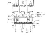
- FIG. 5 is a view showing an integration means suitably used for carrying out the manufacturing method of another embodiment (second embodiment) of the present invention.
- FIG. 6 (a) and 6 (b) are diagrams showing a schematic configuration of an apparatus for manufacturing an elastic sheet that is preferably used for carrying out the manufacturing method of another embodiment (third embodiment) of the present invention.
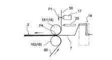
- FIG. 7 is a diagram showing a schematic configuration of a stretchable sheet manufacturing apparatus suitably used for carrying out the manufacturing method of another embodiment (fourth embodiment) of the present invention.
- the present invention forms a portion where the bonding strength between sheets and the fixing strength of the thread-like elastic body to the sheet are different from each other, and the expansion and contraction that can efficiently improve the prevention of slipping out of the thread-like elastic body, flexibility, appearance, etc. It is related with providing the manufacturing method of an adhesive sheet.
- the manufacturing method of the elastic sheet of this invention is demonstrated, referring drawings based on the preferable embodiment.
- the stretchable sheet manufactured in the first embodiment is used for, for example, the waist panel 3 of the unfolded disposable diaper 1. Therefore, first, the unfoldable disposable diaper 1 using the elastic sheet manufactured according to the first embodiment for the waist panel 3 will be described.
- the diaper 1 includes a ventral side A located on the abdomen side of the wearer at the time of wearing, a dorsal side B positioned on the dorsal side, and between the ventral side A and the back side B. It has the absorptive main body 2 which has the crotch part C located, and a pair of left and right waist panels 3 and 3 connected to both left and right outer sides of the back side part B. As shown in FIG. 1, the diaper 1 has a pair of left and right panel members 4, 4 connected to the left and right outer sides of the ventral side A. In the state where the diaper 1 is expanded in a planar shape as shown in FIG.
- the absorbent main body 2 is rectangular, the panel material 4 is trapezoidal, and the long side (lower bottom) side of the trapezoidal panel material 4 is It fixes to the absorptive main body 2 by well-known joining means, such as adhesives, such as a hot-melt-adhesive, and heat sealing
- the direction indicated by X is the width direction of the diaper 1 (absorbent body 2)
- the direction indicated by Y is the longitudinal direction of the diaper 1 (absorbent body 2)
- both directions X and Y are orthogonal to each other. is doing.
- the absorbent main body 2 includes a liquid-permeable top sheet 21, a liquid-impermeable or water-repellent back sheet 22, and a liquid retaining property disposed between these sheets 21 and 22.
- the absorber 23 is provided.
- the top sheet 21 forms a skin facing surface of the diaper 1 (absorbent body 2)
- the back sheet 22 forms a non-skin facing surface of the diaper 1 (absorbent body 2).
- Each of the top sheet 21 and the back sheet 22 has a rectangular shape in plan view having an outer dimension larger than that of the absorber 23, and extends outward from the peripheral edge of the absorber 23. Or joined together with other members.
- the skin-facing surface is a surface directed toward the wearer's skin when worn in the disposable diaper or its constituent members, and the non-skin facing surface is the wearer's skin side when worn in the disposable diapers or its constituent members. The surface is directed to the opposite side.
- a pair of three-dimensional guard forming sheets 24, 24 are arranged over substantially the entire length in the longitudinal direction Y of the absorbent main body 2 on both left and right side portions along the longitudinal direction Y of the absorbent main body 2.
- Each solid guard forming sheet 24 has one side edge (outer edge) along the longitudinal direction Y fixed to the absorbent main body 2 (surface sheet 21), and the other side edge (inner edge) absorbed. It is not fixed to the main body 2 but is a free edge, and one or more thread-like elastic members 25 are fixed to the other edge in a state of being extended in the longitudinal direction Y.
- the pair of three-dimensional guard forming sheets 24, 24 are separated from the surface sheet 21 by the contraction force of the elastic member 25 at the other side edge portion of the crotch part C.
- a pair of solid guards are formed.
- thread-like elastic members 26 for forming leg gathers are arranged in an extended state at portions (leg portions) arranged around the wearer's legs in the left and right sides along the longitudinal direction Y of the absorbent main body 2.
- a pair of leg gathers are formed by contraction of the elastic member 26, and the leg fits well.
- Each of the pair of waist panels 3 and 3 is an elastic sheet in which a plurality of thread-like elastic bodies 7 are bonded and fixed between two sheets 5 and 6 as shown in FIG. In the state expanded to a flat shape as shown in FIG. A plurality of thread-like elastic bodies 7 in each waist panel 3 are arranged at a predetermined interval in the longitudinal direction Y, and are fixed between the sheets 5 and 6 in a state of being extended in the width direction X.
- the waist panel 3 is located on the side opposite to the outer side portion 3A in the width direction X, and the outer side portion 3A to which the fastening tape 8 is fixed by a known joining means such as hot melt adhesive or fusion.
- the waist panel 3 has a known inner side part 3C such as a hot melt adhesive or a fusion bond to the absorbent main body 2 (specifically, for example, between the three-dimensional guard forming sheet 24 and the back sheet 22). It is fixed by the joining means.
- the waist panel 3 has a plurality of center joints 10 at the center in the width direction (X direction) and a pair of end joints 9 and 9 on both sides of the center in the width direction.
- the end joint portion 9 is formed in a strip shape having a predetermined width on each of the outer side portion 3A and the inner side portion 3C of the waist panel 3, and the central joint portion 10 is linear on the stretchable portion 3B.
- the end joint portion 9 and the center joint portion 10 are portions where the sheets 5 and 6 are joined by an adhesive, preferably a hot melt adhesive, respectively.
- the sheets 5 and 6 are continuous over the entire length in the longitudinal direction Y.
- the plurality of thread-like elastic bodies 7 are arranged from the end joint portion 9 of the outer side portion 3A to the end joint portion 9 of the inner side portion 3C, and a pair of end joint portions 9, 9 and a portion overlapping each of the plurality of central joint portions 10 therebetween.
- the thread-like elastic body 7 is fixed in a state of being sandwiched between the two sheets 5 and 6 via an adhesive at a portion overlapping the end joint 9 and the center joint 10.
- those thread-like elastic bodies 7 are fixed between the sheets 5 and 6 via the adhesive.
- each of the end joint portion 9 and the central joint portion 10 the sheets 5 and 6 are directly joined to each other via an adhesive at a portion that does not overlap the thread-like elastic body 7.
- the thread-like elastic body 7 and one or both of the two sheets 5 and 6 sandwiching the elastic body 7 are joined with an adhesive.
- the width W1 of the end joint 9 is larger than the width W2 of the center joint 10, and the end joint 9 is center joined. It is wider than the part 10.
- the end joint portion 9 and the center joint portion 10 are described so that they can be clearly recognized from the outside, but this is not always the case. .
- the end joint 9 and the center joint 10 in the waist panel 3 are formed at a predetermined interval in the width direction X, and between the adjacent end joint 9 and the center joint 10 and the adjacent center. Between the joint portions 10 is a non-adhesive region where no adhesive is disposed between the sheets 5 and 6. In these non-bonded regions, the thread-like elastic body 7 is not fixed to the sheets 5 and 6. In the waist panel 3 expanded in a planar shape, the thread-like elastic body 7 is in an extended state in the stretchable part 3B, and outward (in the direction in which the fastening tape 8 protrudes) from the end joint part 9 in the outer side part 3A.
- end side joint portion 9 in the inner side portion 3 ⁇ / b> C is in a relaxed state (non-stretched state) inward (inward in the width direction of the diaper). Further, the end of the longitudinal direction of the thread-like elastic body 7 or the vicinity thereof is fixed to the end joint 9 in an extended state.
- this type of stretchable sheet is used to join each member.
- the adhesive is preferably a hot melt type (hot melt adhesive).
- each part in the diaper 1 is demonstrated.
- various types conventionally used in the technical field can be used.
- various liquid-permeable sheet materials such as a nonwoven fabric and an apertured film can be used.
- various liquid impervious materials such as a resin film having no moisture permeability, a resin film having fine pores and moisture permeability, a nonwoven fabric such as a water-repellent nonwoven fabric, and a laminate of these and other sheets. Or water repellent materials can be used.
- a fiber aggregate such as pulp fiber or a non-woven fabric or an absorbent core formed by holding particles of a water-absorbing polymer can be used, and the absorbent core is made of water-permeable thin paper or non-woven fabric. What was coat
- seat can also be used.
- the three-dimensional guard forming sheet 24 constituting the three-dimensional guard a stretchable film, a nonwoven fabric, a woven fabric, or a laminated sheet thereof can be used.
- the panel material 4 what can be used as the sheet
- the sheets 5 and 6 constituting the waist panel 3 for example, non-woven fabrics, woven fabrics, knitted fabrics, papers, resin films by various manufacturing methods such as air-through nonwoven fabrics, heat roll nonwoven fabrics, spunlace nonwoven fabrics, spunbond nonwoven fabrics, and meltblown nonwoven fabrics. Etc., and a sheet material obtained by laminating and integrating these two or more can be used.
- the fastening tape 8 for example, a tape obtained by attaching a hook member of a mechanical fastener to one surface of a tape base material such as a nonwoven fabric by heat fusion, an adhesive, or the like can be used.
- Examples of the elastic member 25 constituting the three-dimensional guard and the elastic member 26 for forming leg gathers include natural rubber, polyurethane, polystyrene-polyisoprene copolymer, polystyrene-polybutadiene copolymer, ethyl acrylate-ethylene.
- a thread-like stretchable material made of a polyethylene- ⁇ -olefin copolymer such as the above can be used.
- the thread-like elastic body and elastic member according to the present invention include not only those having a circular or square cross section, but also those having a narrow band shape such as an ellipse or a rectangular cross section, and also those of a multifilament type.
- variety (or diameter) of the thread-like elastic body which concerns on this invention is 0.1 mm or more and 3 mm or less, for example, Preferably it is 1 mm or less.
- variety (or diameter) of an elastic member is 0.1 mm or more and 5 mm or less, for example, Preferably they are 0.1 mm or more and 3 mm or less.
- the manufacturing apparatus 11 is an apparatus that continuously manufactures a strip-shaped stretchable sheet 3 ′ that is a raw fabric of the waist panel 3 (stretchable sheet).
- the conveyance means 16 and the rotation means (elastic body winding means) 14 for elastic body winding which winds the thread-like elastic body 7 in a continuously extended state are provided on the conveyance means 16.
- the conveying means 16 includes a pair of conveying belts 12 and 13 spaced apart in a direction (CD; Cross-machine Direction) orthogonal to the conveying direction (MD; Machine-Direction) of the belt-like sheets 50, 60, and is elastic in the form of a thread.
- the body 7 is wound around the pair of conveyor belts 12 and 13 by the rotating arm 14 in an extended state in a direction crossing the conveyance direction y.
- the belt-like sheets 50 and 60 are original sheets of the sheets 5 and 6 constituting the waist panel 3.
- the direction indicated by the symbol y (y direction) indicates the conveyance direction (MD) of the belt-like sheets 50 and 60
- the direction indicated by the symbol x (x direction) indicates CD.
- the y direction (MD) coincides with the conveyance direction of the thread-like elastic body 7 wound around the conveyance means 16 (conveyance belts 12 and 13) and the conveyance direction of the stretchable sheet 3 ′, and further, the diaper 1 (absorbent body). This also coincides with the longitudinal direction Y of 2) (see FIG. 1).
- the x direction (CD) coincides with the width direction of the belt-like sheets 50 and 60, and further coincides with the width direction X (see FIG. 1) of the diaper 1 (absorbent body 2).
- a direction (z direction) indicated by a symbol z in FIG. 3 indicates a direction in which the pair of nip rolls 181 and 182 of the integration unit 18 face each other.
- the manufacturing apparatus 11 continuously feeds the thread-like elastic body 7 and introduces the thread-like elastic body 7 into a rotating arm (elastic body winding means) 14 in an expanded state.
- the coating device 17 provided, the integration means 18 for fixing the stretched elastic fiber 7 between the pair of strip sheets 50, 60 using the pair of nip rolls 181, 182, and the conveying direction of the strip sheets 50, 60
- a cutting hand that cuts the thread-like elastic body 7 extending outward from both ends along the (y direction) and releases the wound state of the thread-like elastic body 7 around the transport means 16 (transport belts 12 and 13). It is and a 19.
- the conveying belt 12 of the conveying means 16 is an endless rotating belt, and includes an upper belt 12a and a lower belt 12b.
- the upper belt 12a is stretched between two pulleys whose rotation axis direction is arranged in the z direction, one of which is a pulley 122 arranged on the upstream side of the integration means 18, The other one is a pulley 121 arranged on the downstream side of the integration means 18.
- the lower belt 12b is stretched between two other pulleys whose rotation axis direction is arranged in the z direction, one of which is upstream of the integration means 18 and below the pulley 122.
- the other is a pulley 124 arranged below the pulley 121 on which the upper belt 12a is bridged on the downstream side of the integration means 18.
- Each pulley is arranged outside the end along the conveyance direction (y direction) of the belt-like sheets 50 and 60.
- Servo motors (not shown) are connected to the pulleys 121 and 124 on the downstream side, and the rotation speeds of the upper belt 12a and the lower belt 12b can be changed by the servo motors.
- the conveying belt 13 of the conveying means 16 is also an endless rotating belt like the conveying belt 12, and is composed of an upper belt 13a and a lower belt 13b in two upper and lower stages as shown in FIG.
- the conveyor belt 13 is configured in the same manner as the conveyor belt 12, and the belts 13 a and 13 b are respectively two pulleys 132 and 131 or pulleys 135 arranged on the upstream side and the downstream side with the integration unit 18 interposed therebetween. , 134.
- Each of the upper belt 13a and the lower belt 13b can be driven and changed in rotational speed by the same mechanism as the upper and lower belts 12a and 12b of the conveyor belt 12.
- the conveyor belt 12 (upper belt 12a, lower belt 12b) and the conveyor belt 13 (upper belt 13a, lower belt 13b) are respectively stretched over the pulleys, thereby a pair of nip rolls 181 and 182 (integrating means 18). ) From the upstream side to the downstream side. As shown in FIG. 2, the belts 12 and 13 are located outside the end portions along the conveying direction (y direction) of the belt-like sheets 50 and 60 and are arranged symmetrically with respect to each other. Both belts 12 and 13 rotate so that their outer peripheral sides move in the y direction. Both belts 12 and 13 are preferably timing belts.
- the rotational speeds of the belts 12 and 13, that is, the rotational speed of a servo motor (not shown) disposed in a drive unit of a downstream pulley (not shown) is controlled by a control unit (not shown) provided in the manufacturing apparatus 11. ).
- the rotary arm (elastic body winding means) 14 includes an arm portion 141 having a shaft portion 142, a circumferential portion 143, and a connecting portion 144, and a center line of the shaft portion 142 as a rotation axis. And a drive mechanism 147 that rotates the arm portion 141.
- the connecting portion 144 is coupled to each of the shaft portion 142 and the rotating portion 143 at an angle, and the rotating portion 143 and the shaft portion 142 are substantially parallel.
- the shaft portion 142 has an introduction port 145 for the thread-like elastic body 7 at one end thereof, and the rotating portion 143 has a lead-out port 146 for the thread-like elastic body 7 at one end thereof.
- the thread-like elastic body 7 introduced from the introduction port 145 is smoothly led out from the lead-out port 146 through the shaft portion 142, the connecting portion 144, and the rotating portion 143.
- Various known members a driven roll, a low friction member, etc. that can reduce friction with the thread-like elastic body 7 can be disposed in the bent portion of the arm portion 141, the outlet port 146, and the like.
- the circulating portion 143 is arranged such that the outlet 146 is located downstream of the upstream end of the transport belt 12 (upper belt 12a, lower belt 12b) and the transport belt 13 (upper belt 13a, lower belt 13b). ing.
- a servo motor 148 is attached to the drive portion (shaft portion 142) of the rotary arm 14 (elastic body winding means), and the rotating portion 143 is moved to both sides by the rotation of the servo motor 148. Circulate around the outer periphery of the belt 12,13. The diameter of the locus along which the outlet 146 rotates is greater than the distance between the outer surfaces of the pair of conveyor belts 12 and 13.
- the thread-like elastic body 7 taken in can be continuously wound around the upstream end portions of the belts 12 and 13 and the outer peripheral sides thereof.
- the rotation speed of the rotary arm 14, that is, the rotation speed of the servo motor 148 is controlled by a control unit (not shown) included in the manufacturing apparatus 11.
- the elastic body supply means 15 includes a roll body 70 around which the thread-like elastic body 7 is wound, a tensor 151 that is positioned downstream of the roll body 70 and applies tension to the thread-like elastic body 7 by a brake, A feeding roll 152 is provided on the downstream side of the tensor 151 to feed the thread-like elastic body 7 from the roll body 70, and a tension measuring device 153 is provided on the downstream side of the feeding roll 152 for measuring the tension.
- the rotation axis of the feeding roll 152 is arranged in the x direction (direction perpendicular to the sheet conveyance direction).
- a servo motor (not shown) is attached to the driving unit of the feeding roll 152.
- the feeding roll 152 is used with the thread-like elastic body 7 wound twice around the outer periphery thereof.
- a control unit (not shown) provided in the manufacturing apparatus 11 controls the rotational speed of a servo motor (not shown), that is, the rotational speed of the feeding roll 152, based on the detection output from the tension measuring device 153. 7 can be unwound from the roll body 70.
- the elastic body supply means 15 includes a feed roll 156 located on the downstream side of the feeding roll 152 as shown in FIG.
- the feed roll 156 is arranged between the rotary arm (elastic body winding means) 14 and the feeding roll 152, and the rotation axis direction thereof is arranged in the x direction.
- the feed roll 156 has a servo motor (not shown) attached to its drive unit.
- the rotational speed of a servo motor (not shown), that is, the rotational speed of the feed roll 156 is controlled by a control unit (not shown) provided in the manufacturing apparatus 11.
- the coating device 17 includes a coating unit 172 that applies an adhesive to the belt-like sheet 50.
- the application means 172 is supplied with an adhesive from a storage tank of an adhesive (not shown) via a predetermined supply path.
- the application unit 172 discharges an adhesive 10 ′ (adhesive for forming the central joint) for forming the central joint 10 on the stretchable sheet 3 ′.
- a discharge port F that discharges an adhesive 9 ′ (adhesive for forming an end joint) for forming the end joint 9 in the stretchable sheet 3 ′.
- the discharge port E is provided at a position facing the central portion in the width direction of the belt-like sheet 50
- the discharge port F is provided at a position facing both ends near both ends of the central portion in the width direction of the belt-like sheet 50. ing.
- the discharge port E and the discharge port F are connected to the same common storage tank (not shown) and the supply path 173, and the same type of adhesive is connected to both the discharge ports E. , F and applied to the belt-like sheet 50.
- a known adhesive coating means can be used, and a contact-type coating means in which the coating head of the coating means contacts the surface to be coated may be used, and the coating head of the coating means does not contact the surface to be coated.
- Mold application means may be used.
- the contact coating means include a slot coater, a gravure coater, and a rotary screen coater.
- the non-contact type application means include a spray coater, a bead coater, and a curtain coater.
- tube, a flexible tube, etc. can be used as a supply path.
- the integration unit 18 includes a pair of nip rolls 181 and 182.
- the pair of nip rolls 181 and 182 are located between the inner peripheral side of the transport belt 12 (upper belt 12a and lower belt 12b) and the inner peripheral side of the transport belt 13 (upper belt 13a and lower belt 13b).
- one nip roll 181 has a small diameter portion M having a relatively small diameter at the center in the axial direction.
- One having large diameter portions S, S having relatively large diameters at both ends in the axial length direction is used.
- the other nip roll 182 has a constant diameter over the entire width of the belt-like sheets 50 and 60.
- the small diameter portion M of the nip roll 181 pressurizes a portion of the belt-like sheets 50 and 60 where the adhesive 10 ′ for forming the central joint portion is interposed therebetween, thereby increasing the size of the nip roll 181.
- the diameter portions S and S are formed so as to pressurize the portions of the belt-like sheets 50 and 60 where the adhesives 9 ′ and 9 ′ for forming end joint portions are interposed therebetween.
- nip roll 182 a cylindrical roll made of metal or a cylindrical roll made of low hardness silicon rubber can be used.
- nip roll 181 a nip roll having the same configuration as that of the nip roll 182 can be used except that the nip roll 181 has a cylindrical shape having a step on the peripheral surface.
- the pair of nip rolls 181 and 182 has a servo motor (not shown) attached to one of the drive units, and the rotation speed is controlled by a control unit (not shown) included in the manufacturing apparatus 11.
- Drive transmission gears are attached to the respective rotation shafts of the pair of nip rolls 181 and 182.
- the rotation speed of a servo motor (not shown), that is, the rotation speed of one of the pair of nip rolls 181 and 182 can be controlled based on the production speed of the stretchable sheet.
- the drive transmission gear is engaged, the driving force is transmitted to the other of the pair of nip rolls 181 and 182, and the pair of nip rolls 181 and 182 can be rotated.
- the bearing portions of the pair of nip rolls 181 and 182 use forces such as hydraulic pressure, pneumatic pressure, and spring to securely fix the stretched thread-like elastic body 7 between the pair of belt-like sheets 50 and 60. Each bearing part is pressurized.
- the cutting means 19 includes a cutter 190 in which a portion to which the conveyed elastic thread 7 hits is a sharp cutting blade.
- the cutter 190 is arranged at a position where the thread-like elastic body 7 hits by a support body (not shown), and the thread-like elastic body 7 is cut by being conveyed by the conveyor belts 12 and 13 and being pressed against the cutter 190.
- the position of the cutting means 19 is slightly downstream of the part where the thread-like elastic body 7 and the belt-like sheets 50 and 60 are integrated by the pair of nip rolls 181 and 182.
- various known devices that can cut the thread-like elastic body 7 can be used without any particular limitation.
- a cutter roll having a cutting blade extending in the circumferential direction on the outer peripheral surface and the cutting blade are received.
- a roll cutter equipped with an anvil roll can be used, and a cutting means capable of cutting the thread-like elastic body 7 with a laser or heat may be used.
- the manufacturing apparatus 11 having such a configuration is used to manufacture the waist panel 3 and the elastic sheet 3 ′ that is a continuous body of the waist panel 3 as follows.
- the thread-like elastic body 7 is continuously fed out, and the fed-out thread-like elastic body 7 is introduced into a rotating arm 14 as an elastic body winding means in an expanded state (supplying step). . More specifically, the thread-like elastic body 7 is continuously fed out from the winding roll 70 around which the thread-like elastic body 7 is wound using the feeding roll 152. At the time of unwinding, the rotational speed of the unwinding roll 152 is adjusted by a control unit (not shown) provided in the manufacturing apparatus 11 based on the detection output of the tension of the filamentous elastic body 7 by the tension measuring device 153, and a predetermined tension is applied. Then, the thread-like elastic body 7 is unwound from the winding roll 70.
- a control unit not shown
- the thread-like elastic body 7 is introduced into the rotating arm 14.
- the speed of the thread-like elastic body 7 introduced into the rotating arm 14 (elastic body winding means) by the feed roll 156 described above. Is adjusted to a constant speed and introduced.
- the introduction speed is set to a speed according to the winding speed wound around the transport means 16 (the pair of transport belts 12 and 13).
- the thread-like elastic body 7 is transferred to the conveying means 16 (the pair of conveying belts 12 and 13) using the rotary arm 14 (elastic winding means), and the belt-like sheets 50 and 60.
- the wound elastic body 7 is wound in a stretched direction in a direction intersecting with the transport direction (y direction) of the sheet, and the wound thread-like elastic body 7 is transported between the pair of belt-like sheets 50 and 60 by the transport means 16 (transport process). More specifically, as shown in FIG. 3, the thread-like elastic body 7 supplied into the rotating arm 14 in the extended state is introduced into the arm portion 141 through the introduction port 145, and the shaft portion 142, the connecting portion 144, and the rotating portion.
- the thread-like elastic body 7 immediately after being wound around the transport means 16 forms a winding length in a direction crossing the y direction (sheet transport direction). However, it does not extend in the direction orthogonal to the y direction (x direction).
- the rotational speed of the upper belt 12a may be made slower than the rotational speed of the lower belt 12b, and in the conveying belt 13, the rotational speed of the lower belt 13b may be made slower than the rotational speed of the upper belt 13a.
- the inclination (extension direction) of the thread-like elastic body 7 can be gradually changed during the conveyance in the y direction.
- the slant of the thread-like elastic body 7 can be corrected from the direction different from the original x direction to the x direction before being conveyed between the belt-like sheets 50 and 60 (between the pair of nip rolls 181 and 182). it can.
- the belt-like sheets 50 and 60 are both side portions (both ends in the x direction) along the conveying direction (y direction) by the sailor or the like (not shown) before applying the adhesive. It is folded back (on the side opposite to the surface facing the other belt-like sheet to be joined). And as shown to Fig.4 (a), for application
- the adhesive 10 ′ is applied such that a plurality of narrow-line adhesive application portions are formed in a continuous linear shape along the conveying direction of the sheet 50.
- the adhesive 9 ′ is applied so that two strip-shaped adhesive application portions are formed in a continuous linear shape along the conveying direction of the sheet 50.
- the composite sheet 30A (elastic sheet 3 ′) is obtained by applying pressure integrally (integration step). More specifically, the stretched thread-like elastic body 7 continuously wound around the transport means 16 (the pair of transport belts 12 and 13) is supplied between the pair of nip rolls 181 and 182, and the pair of belt-like sheets 50 is supplied. , 60 are supplied and merged so as to oppose the thread-like elastic body 7 being conveyed. The two sheets 50 and 60 are joined together so that the thread-like elastic body 7 is fixed therebetween, and the sheet-like elastic body 7 is sandwiched and fixed between the two sheets 50 and 60 and introduced into the pair of nip rolls 181 and 182. Pressure.
- the thread-like elastic body 7 in an elongated state extending outward from the side edge along the conveyance direction (y direction) of the composite sheet 30A is cut to shrink the thread-like elastic body 7, Cut end portions generated by cutting the thread-like elastic body 7 are present on one side portion and the other side portion along the y direction of the composite sheet 30A (cutting step). More specifically, along the conveyance direction (y direction) of the composite sheet 30A (the pair of belt-like sheets 50, 60) in the thread-like elastic body 7 that is stretched between the pair of conveyance belts 12, 13. The portions extending from both side edges (both edges of the composite sheet 30A in the x direction) are cut by the above-described cutter 190.
- the winding state of the thread-like elastic body 7 around the pair of conveying belts 12 and 13 (conveying means 16) is released, and the belt-like stretchable sheet 3 ′ is formed on the belt-like sheets 50 and 60. Both sides along the y-direction (both ends in the x-direction) are obtained in a state of being folded back to the outer surface side.
- the belt-like sheets 50 and 60 constituting the belt-like stretchable sheet 3 ′ are not folded using a sailor or the like (not shown), as shown in FIG. A belt-like stretchable sheet 3 ′ is obtained.
- the band-shaped stretchable sheet 3 ′ thus obtained is cut into a predetermined unit length (product length) by a known cutting means (not shown) to obtain the intended waist panel 3 (stretchable sheet). .
- the adhesive 9 ′ for the end joint portion is interposed between the large-diameter portions S, S of the nip roll 181 and the nip roll 182 in the belt-like sheets 50, 60.
- the portion of the belt-like sheets 50, 60 where the adhesive 10 ′ for the central joint portion is interposed between the two is pressed.
- the adhesive 9 ′ for the end joint portion generates clearance between the peripheral surface of the large diameter portion S and the peripheral surface of the nip roll 182 (between the peripheral surfaces).
- the adhesive 10 ′ for forming the central joint portion is pressed between the peripheral surface of the small-diameter portion M and the peripheral surface of the nip roll 182 (the distance) is relatively strongly pressed at a relatively narrow portion. Between perimeters Are relatively weakly pressed at a relatively wide portion. That is, the bonding conditions in the integration step between the pair of belt-like sheets differ between the adhesive 10 ′ for forming the central joint and the adhesive 9 ′ for forming the end joint. In detail, the pressure which pressurizes adhesive agent 9 'for edge part junction parts is stronger compared with the pressure which pressurizes adhesive agent 10' for center junction part formation.
- the end joints 9 and 9 are formed in the composite sheet 30A and the stretchable sheet 3 ′ by strongly joining the belt-like sheets 50 and 60 via the end joint adhesive 9 ′.
- the thread-like elastic body 7 is relatively strongly fixed as compared with the center joint part 10, and the thread-like elastic body 7 can be prevented from coming off.
- the central joint is formed by joining the belt-like sheets 50 and 60 via the adhesive 10 ′ for forming the central joint. 10 is formed, but the adhesive 10 ′ forming the central joint 10 is pressed more weakly than the adhesive 9 ′ forming the end joint 9, so that the adhesive 10 ′ is crushed.
- the region of the central joint portion 10 in the composite sheet 30A and the stretchable sheet 3 ′ is excellent in air permeability and excellent in flexibility.
- the elastic sheet 3 is less likely to come out of the thread-like elastic body 7 from the end joints 9 and 9 and is excellent in air permeability, flexibility and stretchability between the end joints 9 and 9. 'And the waist panel 3 can be manufactured efficiently.
- the central joint 10 is formed by pressing the adhesive 10 ′ relatively weakly as compared with the end joint 9, so that the central joint 10 has a gap between the belt-like sheets 50 and 60.
- the center joint 10 is formed between the pair of end joints 9, although the joints are relatively weaker than the end joints 9 and the thread-like elastic body 7 is fixed relatively weakly. For this reason, in the central joint portion 10, problems such as separation between the sheets 50 and 60 and removal of the thread-like elastic body 7 are unlikely to occur.
- the width W1 (see FIG. 1) of the end joint 9 is preferably 3 mm or more, more preferably 5 mm or more, from the viewpoint of secure fixing of the end of the thread-like elastic body 7 or the vicinity thereof.
- it is 20 mm or less, More preferably, it is 10 mm or less, Preferably it is 3 mm or more and 20 mm or less, More preferably, it is 5 mm or more and 10 mm or less.
- the width W2 (see FIG. 1) of the central joint portion 10 is preferably 0.1 mm or more, more preferably from the viewpoint of forming the stretchable portion 10B having good air permeability and stretchability between the end joint portions 9.
- the interval W3 (see FIG. 1) between the adjacent end joints 9 and the central joint 10 and the interval W4 (see FIG. 1) between the two adjacent central joints 10 and 10 are respectively
- the thickness is preferably 1 mm or more, more preferably 3 mm or more, and preferably 10 mm or less, more preferably 7 mm or less, and preferably 1 mm or more and 10 mm or less, more preferably 3 mm or more and 7 mm or less.
- the interval W5 see FIG.
- 1) between the two thread-like elastic bodies 7 and 7 adjacent in the Y direction is preferably 2 mm or more, more preferably 4 mm or more, and preferably 12 m or less, more preferably 10 mm. In addition, it is preferably 2 mm or more and 12 mm or less, more preferably 4 mm or more and 10 mm or less.
- one roll 181 is provided with large-diameter portions S, S and small-diameter portions M to press the adhesive 10 ′ for forming the central joint, and for forming the end joint
- the pressure applied to the pair of belt-like sheets 50, 60 is different from the portion where the adhesive 9 'is pressed, the difference in diameter between the large diameter portions S, S and the small diameter portion M is the belt-like sheets 50, 60.
- the radius Rs and the small diameter of the large diameter portions S and S can be appropriately determined depending on the thickness of the large diameter portions S and S from the point of providing a sufficient pressure difference between the large diameter portions S and S and the small diameter portion M.
- the difference in radius Rm (Rs ⁇ Rm) of the part M and the difference in clearance between the large diameter parts S, S and the small diameter part M are preferably 0.01 mm or more, for example, 0.01 mm or more and 1 mm or less. More preferably.
- the diaper 1 provided with the waist panel 3 can be manufactured by the following method, for example. That is, the fastening tape 8 is intermittently fixed to the stretchable sheet 3 ′ obtained as described above, and then cut into the size of each diaper, or the stretchable sheet 3 ′ is sized for each diaper.
- the waist panel 3 as shown in FIG. 1 is obtained by fixing the fastening tape 8 after cutting into a size. In the manufacture of the waist panel 3, it is preferable to obtain a pair of left and right waist panels 3, 3 having different fastening tape 8 mounting positions from the two stretchable sheets 3 '.
- the continuous body of the top sheet 21 is continuously transported, and the continuous body of the three-dimensional guard forming sheet 24 is joined to each of both sides in the transport direction to obtain a composite continuous sheet. . Then, while continuously conveying the composite continuous sheet, a pair of left and right waist panels 3, 3 obtained from the two stretchable sheets 3 'is provided with an interval in the flow direction of the composite continuous sheet with respect to both sides thereof. And fix it sequentially. And the continuous body of the back surface sheet 22 is merged and integrated so that the absorbers 23, 23.
- a plurality of elastic members 25 and a panel material 34 in an extended state are arranged on both sides of the absorber 23, and they are also continuous between the continuous body of the three-dimensional guard forming sheet 24 and the back sheet 22. Fix between the body.
- a continuous body of diapers 1 is manufactured in which a plurality of pairs of waist panels 3 are fixed to both sides of the continuous body of the absorbent main body 2.
- the conveyance direction (y direction) of the continuous body of the absorbent main body 2 and the conveyance direction (y direction) when manufacturing the waist panel 3 (elastic sheet) are the same direction, and the waist panel 3 (extension and contraction). It is not necessary to invert the adhesive sheet) by 90 °.
- many diapers 1 can be manufactured one by one by cutting the continuous body of diapers 1 into the size of each diaper 1 by a known cutting means (not shown).
- a pair of band-like sheets 50 and 60 are used in an integration process in which the pair of belt-like sheets 50 and 60 are integrally pressed with the thread-like elastic body 7 sandwiched therebetween.
- the rolls 181 and 182 one in which at least one roll 181 is composed of a plurality of short rolls 181 s, 181 m and 181 s arranged in the width direction (x direction) of the pair of belt-like sheets 50 and 60 is used.
- the adhesive 10 'for forming a central joint similar to the central joint in the form is applied, and a plurality of the belt-like sheets 50 and 60 are sandwiched between the thread-like elastic bodies 7 therebetween.
- the pressure is applied between a roll 181 composed of a short roll and a roll 182 that is not divided into a plurality of short rolls.
- the short rolls 181s and 181s are arranged at positions overlapping the application position of the adhesive 9 ′ for forming the end joint in the width direction of the belt-like sheets 50 and 60, and the short roll 181m is used for forming the central joint. It arrange
- the short rolls 181 s, 181 m, 181 s are arranged at the same position in the flow direction (y direction) of the belt-like sheets 50, 60, and each roll has a common single roll 182. It faces the peripheral surface.
- the short rolls 181s, 181m, and 181s in the illustrated example are respectively a shaft support 181a that supports a rotating shaft, a lifting mechanism 181b that vertically displaces the shaft support 181a, and a pressure gauge 181c that measures the pressure applied by the roll. It has.
- the elevating mechanism 181b various known ones such as a hydraulic cylinder, an air cylinder, and a screw jack can be used.
- the short rolls 181 s and 181 s that pressurize the adhesive 9 ′ for forming the end joint portion are a pair of strips rather than the short roll 181 m that presses the adhesive 10 ′ for forming the central joint portion.
- the thread-like elastic body 7 and the belt-like sheets 50 and 60 are integrated while maintaining or controlling the sheets 50 and 60 to be more strongly pressurized.
- the clearance between the short rolls 181s, 181s and the roll 182 is set to be narrower than the clearance between the short roll 181m and the roll 182, and the value of each clearance is fixed, and the thread-like elastic body 7 and
- the belt-like sheets 50 and 60 may be pressurized, or the pressure applied by the short roll 181s and the pressure applied by the short roll 181m are monitored, and the pressure difference is constantly maintained within a certain range.
- the thread-like elastic body 7 and the belt-like sheets 50 and 60 may be pressurized while moving the roll up and down.
- Various known automatic control devices can be used for monitoring pressure and maintaining pressure by raising and lowering the short roll.
- the joining conditions in the integration step between the pair of belt-like sheets are different between the adhesive 10 ′ for forming the central joint and the adhesive 9 ′ for forming the end joint. . More specifically, the pressure of pressing when joining a pair of belt-like sheets via an adhesive is varied. That is, according to the manufacturing method of the second embodiment, between the short rolls 181 s, 181 s and the nip roll 182, the portion of the belt-like sheets 50, 60 where the adhesive 9 ′ for the end joint portion is interposed therebetween.
- the portion of the belt-like sheets 50, 60 where the adhesive 10 ′ for the central joint is interposed is relatively weakly pressed between the short roll 181 m and the nip roll 182. Is done. Thereby, like the first embodiment, the thread-like elastic body 7 is unlikely to come off from the end joints 9 and 9, and the end joints 9 and 9 are excellent in air permeability, flexibility and stretchability.
- the stretchable sheet 3 ′ and the waist panel 3 can be efficiently manufactured.
- FIG.6 (a) and FIG.6 (b) As the manufacturing apparatus of elastic sheet 3 ', one side of elastic sheet 3' to manufacture is shown.
- a sheet provided downstream of each of the first rolls 183 and 184 and the second rolls 185 and 184 in the conveyance direction (y direction) of the sheets 50 and 60 is used.
- the adhesive agent 9 'for forming the edge part junction part 9 and the center junction part 10 are formed in the single side
- the belt-like sheet 50 and the other belt-like sheet 60 are joined together so that the thread-like elastic body 7 is sandwiched between the two sheets 50 and 60.
- part in which adhesive part 9 ', 9' for edge part junction formation interposes between a pair of 1st rolls 183,184 or a pair of 2nd rolls 185. 184 and pressurizing.
- the bonding conditions in the integration step between the pair of belt-like sheets are different between the adhesive 10 ′ for forming the central bonded portion and the adhesive 9 ′ for forming the edge bonded portion. .
- the adhesive 9 ′ and the adhesive 10 ′ for forming the central joint are applied.
- the adhesive 9 ′ is applied by the first and second rolls.
- the time until pressing is different from the time from applying the adhesive 10 ′ to the belt-like sheet 50 until pressing with the third roll.
- the adhesive 9 'for forming the end joint is applied and then the adhesive 9' is pressed with the first and second rolls. Is shorter than the time from application of the adhesive 10 ′ for forming the central joint portion to pressing of the adhesive 10 ′ between the third rolls. For this reason, when the temperature and type when applied to the belt-like sheet 50, the basis weight to be applied, etc. are the same, the adhesive 9 'is higher in temperature than the adhesive 10', that is, in a state where the viscosity is low. , 60 together with pressure.
- the end joint 9 where the sheets 50 and 60 are joined by the adhesive 9 ′ is more suitable for the sheets 50 and 60 than the central joint 10 where the sheets 50 and 60 are joined by the adhesive 10 ′.
- the bonding strength between the yarns and the fixing strength of the thread-like elastic body to the sheets 50 and 60 are relatively high.
- the adhesive 10 ′ having a lower temperature that is, having a higher viscosity
- the air permeability and stretchability are reduced by the adhesive 10 ′. Hard to occur.
- the thread-like elastic body 7 is unlikely to come off from the end joints 9 and 9, and the gap between the end joints 9 and 9 is air permeable, flexible, and stretchable.
- the elastic sheet 3 ′ and the waist panel 3 excellent in the above can be efficiently manufactured.
- the adhesive 10 ' is pressed with a roll from the coating position P1 of the adhesive 10' to the distance (L1) from the coating position P1 of the adhesive 9 'to the position P2 where the adhesive 9' is pressed with a roll.
- the ratio (L2 / L1) of the distance (L2) to the position P3 is preferably 1.1 or more, more preferably 1.2 or more, preferably 5 or less, more preferably 2 or less, , Preferably 1.1 or more and 5 or less, more preferably 1.2 or more and 2 or less.
- the distances L1 and L2 are measured along the transport path of the belt-like sheet on which each adhesive is applied.
- one roll 183 of the 1st rolls 183 and 184 and one roll 185 of the 2nd rolls 185 and 184 are shown in FIG.
- the other roll 184 of the first rolls 183 and 184 and the other roll 184 of the second rolls 185 and 184 are separated from each other in the belt-like sheet 50, A single cylindrical roll having a uniform diameter over substantially the entire width of 60.
- separate rolls spaced in the x direction may be used as the first roll 184 and the second roll 184.
- both rolls may have a common rotating shaft, or both rolls are independent of each other. And you may have a rotating shaft.
- an apparatus for manufacturing the stretchable sheet 3 ′ shown in FIG. 7 is used.
- the stretch sheet 3 ′ shown in FIG. 7 has a substantially full width of the belt-like sheets 50, 60 as the integrated means 18 for fixing the stretched thread-like elastic body 7 between the pair of belt-like sheets 50, 60, respectively.
- an adhesive 9 ′ for forming an end joint and an adhesive 10 ′ for forming a central joint are applied to the belt-like sheet 50.
- a cooling means 20 for cooling the adhesive is provided between the coating device 17 to be worked and the portion P4 where the belt-like sheets 50 and 60 are pressed by the pair of nip rolls 181 ′ and 182.
- the configuration of the coating device 17 is the same as that of the coating device 17 shown in FIG.
- the cooling means 20 cools only the adhesive 10 ′ of the adhesive 9 ′ and the adhesive 10 ′, or cools the adhesive 10 ′ more strongly than the adhesive 9 ′.
- a cool air device that cools the adhesive by blowing cool air, a contact type chill roll (cooling roll), or the like can be used.
- a cold air device is preferred because it is advantageous.
- the bonding conditions in the integration step between the pair of belt-like sheets are made different between the adhesive 10 ′ for forming the central bonded portion and the adhesive 9 ′ for forming the edge bonded portion. .
- the adhesive 10 ' is cooled by the cooling means 20, and the temperature of the adhesive 10' is lowered.
- the adhesive 9 ′ is not cooled substantially or the degree of cooling is weakened, and the temperature is higher than that of the adhesive 10 ′.
- the belt-like sheet 50 and the other belt-like sheet 60 are joined together so as to sandwich the thread-like elastic body 7 between the two sheets 50 and 60, and then sandwiched between the pair of rolls 181 'and 182. Pressurize.
- the adhesive 9 ′ is pressed together with the sheets 50 and 60 in a state where the temperature is higher than that of the adhesive 10 ′. Therefore, the adhesive between the sheets 50 and 60 is joined with the adhesive 10 ′ by using an adhesive having a kind and temperature range in which a high joining strength can be obtained due to a lower viscosity than a lower one at a higher temperature.
- the end joint 9 in which the sheets 50 and 60 are joined with the adhesive 9 ′ is stronger than the central joint 10 that is made with respect to the joint strength between the sheets 50 and 60 and the sheets 50 and 60 of the filamentous elastic body. Fixing strength is relatively high.
- the adhesive 10 ′ having a lower temperature that is, having a higher viscosity
- the thread-like elastic body 7 is unlikely to come off from the end joints 9 and 9 and the space between the end joints 9 and 9 is air permeable, flexible and stretchable.
- the elastic sheet 3 ′ and the waist panel 3 excellent in the above can be efficiently manufactured.
- the planar view shape of the pair of waist panels 3 and 3 is a rectangle, but may be a trapezoid or a parallelogram.
- the plan view shape of the waist panel 3 is such that when the stretchable sheet 3 ′ is cut to obtain the pair of waist panels 3 and 3, the portion to be discarded (the portion not used as the waist panel 3) is minimized. It is preferable to do.
- the thread-like elastic body 7 is wound around the pair of transport belts 12 and 13 in a stretched state in a direction intersecting without crossing the y direction (sheet transport direction) and then tilted (stretch direction). ) Is corrected in the direction orthogonal to the y direction (x direction), but it may be fixed to the pair of belt-like sheets 50 and 60 without correcting the angle around the conveyor belts 12 and 13.
- the elastic body winding means includes a disk having a thread-like elastic body introducing portion at the rotating shaft portion and an arm protruding downstream from the disk in the y direction. It is also possible to use one that wraps around the belt and winds the elastic thread around the conveyor belts 12 and 13. Also, as the feed roll 156, as shown in FIG. 3, instead of feeding a material (thread-like elastic body) and feeding the material, a feed roll 156 sandwiching the material with a material may be used. it can.
- a conveyor belt as disclosed in WO2005 / 060910 may be used instead of a pair of conveyor belts.
- a thread support member provided with a screw groove described in FIGS. 4 to 6 of JP-A No. 2002-192641 may be used.
- the end joint is applied to the one strip 50.
- the adhesive 9 ′ for forming the portion may be applied, and the adhesive 10 ′ for forming the central joint portion may be applied to the other belt-shaped sheet 60.
- the adhesive 9 'that forms one end joint may be applied to one belt-like sheet, and the adhesive 9' that forms the other end joint may be applied to the other belt-like sheet.
- an adhesive 10 ′ for forming a part of the plurality of central joints is applied to one belt-like sheet, and an adhesive 10 ′ for forming the other part is applied to the other belt-like sheet. You may apply to.
- the positions of the roll that presses the adhesive 9 ′ for forming the end joint and the roll that presses the adhesive 10 ′ for forming the central joint are shifted in the y direction.
- the adhesive 10 ′ for forming the central joint with the third roll is used instead of pressurizing only the adhesive 10 ′ for forming the central joint with the third roll. You may pressurize both adhesives 9 'for end part junction formation.
- the cooling means 20 is applied.
- the adhesive 10 ' is cooled by the above, but after the adhesive 9' and the adhesive 10 'are applied, the adhesive 9' may be heated without cooling the adhesive 10 ', or the adhesive 10' It is also possible to perform cooling and heating of the adhesive 9 '.
- an end joint 9 having a higher adhesive strength between the sheets 50 and 60 and a higher fixing strength of the thread-like elastic body 7 than the central joint 10
- the adhesive strength between the sheets 50 and 60 and the fixing strength of the thread-like elastic body 7 may be lower than that of the central joint 10.
- the end joint 9 in this case is used, for example, to suppress the movement of the cut end accompanying the contraction of the thread-like elastic body immediately after cutting, and to correct irregular arrangement of the cut end of the thread-like elastic body. Can do.
- the pair of rolls used in the integration process may be both rolls driven by rotating in contact with the belt-like sheet without being driven to rotate.
- the stretchable sheet produced according to the present invention may have only one central joint at the center in the width direction instead of one having a plurality of center joints at the center in the width direction.
- the central joint is preferably wider than the width of each of the end joints on both sides thereof, and more preferably wider than the total width of the end joints on both sides.
- the central joint portion and the end joint portions on both sides thereof may be adjacent or continuous without interposing a non-adhesive region.
- the magnitude of the joining strength of the center joining portion and the end joining portion in the stretchable sheet is, for example, the dimension (length) in the direction corresponding to the transport direction (MD) during manufacture and the transport direction (MD) from each joint portion.
- a test piece having the same dimension (width) in the direction corresponding to the direction (CD) orthogonal to the direction (CD) is obtained, and a peel test (such as a 90 ° peel test) is performed on the test pieces to peel the sheets in the longitudinal direction It can be judged by performing etc.
- the test piece has a length of 65 mm and a width of 30 mm, for example, and the width of the test piece is smaller than the width of the joint of the narrower one when the width of the narrower part is less than 30 mm.
- the pressure for pressurizing the adhesive 9 ′ for the end joint is stronger than the pressure for pressurizing the adhesive 10 ′ for forming the central joint,
- the adhesive 10 'for forming the central joint may be pressed more strongly.
- the time until the adhesive 9 ′ is pressed with the first and second rolls after the adhesive 9 ′ for forming the end joint is applied to the center joint is formed. Although the time from applying the adhesive 10 ′ to pressing the adhesive 10 ′ between the third rolls is shortened, the time until pressing the adhesive 10 ′ for forming the central joint is increased. May be shortened.
- the adhesive 9 ′ for forming the end joint 9 maintains a higher temperature than the adhesive 10 ′ for forming the central joint 10, and the sheet Although the pressure is applied together with 50 and 60, the pressure may be applied in a state where the temperature of the adhesive 10 ′ for forming the central joint 10 is higher. By doing so, the fixing strength of the thread-like elastic body 7 is increased at the central joint portion 10, and the contraction force of the thread-like elastic body 7 bonded and fixed in an extended state is less likely to affect the end joint portion 9.
- the thread-like elastic body 7 is hard to come off and looks good, and the stretchable sheet 3 ′ and the waist panel 3 which are excellent in stretchability and flexible can be efficiently manufactured.
- the stretchable sheet produced by the production method of the present invention includes a waist part of a developed or pant-type disposable diaper, a waist part of a pant-type disposable diaper, and a pant-type sanitary garment. It can also be used for napkins, disposable underwear, disposable mask ear hooks, cleaning sheets, bandages and the like.
- a method for producing a stretchable sheet for continuously producing a stretchable sheet having a pair of end joints on both sides of the central portion in the width direction Using the elastic body winding means, the thread-like elastic body is wound around the thread-like elastic body conveying means so as to extend in a direction crossing the conveying direction, and the wound thread-like elastic body is A conveying step of conveying in the conveying direction by the conveying means; An adhesive application step of applying an adhesive to one or both of the pair of belt-like sheets; The pair of belt-like sheets after the adhesive application step are joined to the thread-like elastic body transported by the transport means, and the pair of belt-like sheets sandwiching the thread-like elastic body are integrally pressed to An integration process for obtaining a stretchable sheet, A method for producing a stretchable sheet, wherein a bonding condition in the integration step between a pair of the belt-like sheets is made different between the adhesive for forming the central joint portion and the adhesive for forming the end joint portion.
- a pair of the belt-like sheets are introduced and pressed between a pair of rolls, and a portion for pressing the adhesive for forming the central joint portion as the pair of rolls, and the end
- ⁇ 3> The production of the elastic sheet according to ⁇ 2>, wherein the pressure for pressurizing the adhesive for forming the end joint is stronger than the pressure for pressurizing the adhesive for forming the central joint.
- the diameter of the portion that pressurizes the adhesive for forming the end joint portion is larger than the diameter of the portion that pressurizes the adhesive for forming the central joint portion.
- At least one of the pair of rolls includes a plurality of short rolls arranged in the width direction of the pair of belt-like sheets, and the plurality of short rolls pressurize the adhesive for forming the end joint portion.
- the short roll is configured to press the pair of belt-like sheets more strongly than the short roll that presses the adhesive for forming the central joint portion.
- ⁇ 6> A difference (Rs ⁇ Rm) between a radius Rs of a portion where the adhesive for forming the end joint portion is pressed and a radius Rm of the portion where the adhesive for forming the central joint is pressed in the roll.
- the difference in clearance between the portion for pressurizing the adhesive for forming the end joint and the portion for pressurizing the adhesive for forming the central joint is preferably 0.01 mm or more, and 0.01 mm or more and 1 mm More preferably, the method for producing a stretchable sheet according to any one of the above items ⁇ 1> to ⁇ 5>.
- the pressure which pressurizes the adhesive for ⁇ 7> said edge part junction part is a manufacturing method of the elastic sheet as described in said ⁇ 2> weak compared with the pressure which pressurizes the adhesive agent for said center junction part formation.
- the pair of the belt-like sheets are introduced and pressed between the pair of rolls, and the adhesive for forming the central joint portion is applied to one or both of the pair of the belt-like sheets.
- a time from when the adhesive is pressed between the pair of rolls to a time from when the adhesive for forming the end joint is applied to when the adhesive is pressed between the pair of rolls.
- the method for producing a stretchable sheet according to ⁇ 8> wherein the time until the adhesive is pressed between a pair of rolls is short.
- a pair of rolls that pressurize the adhesive for the central joint is provided downstream in the conveying direction of the pair of belt-like sheets, rather than a pair of rolls that pressurize the adhesive for the end joints.
- ⁇ 11> Forming the central joint with respect to the distance (L1) from the application position P1 of the adhesive for the end joint to the position P2 where the adhesive for the end joint is pressed with a roll.
- the ratio (L2 / L1) of the distance (L2) from the adhesive application position P1 to the position P3 where the adhesive for forming the central joint is pressed with a roll is preferably 1.1 or more, more preferably Is 1.2 or more, preferably 5 or less, more preferably 2 or less, and preferably 1.1 or more and 5 or less, more preferably 1.2 or more and 2 or less, ⁇ 8>
- One of the pair of rolls that pressurizes one of the end joints, and one of the pair of rolls that presses the other of the end joints conveys the belt-like sheet.
- the other roll of the pair of rolls that pressurizes one of the end joints, and the other roll of the pair of rolls that pressurizes the other of the end joints The method for producing an elastic sheet according to the above ⁇ 12>, which is a common cylindrical roll having a uniform diameter over substantially the entire width.
- One of the pair of rolls that pressurizes one of the end joints, and one of the pair of rolls that presses the other of the end joints conveys the belt-like sheet.
- the time from pressing the adhesive between the pair of rolls is applied.
- the adhesive for the central joint or the adhesive for the end joint is cooled or heated, and in the integration step, between the pair of belt-like sheets, The method for producing a stretchable sheet according to ⁇ 1>, wherein the pair of belt-like sheets are pressed between a pair of rolls in a state where the two adhesives having different temperatures due to cooling or heating are interposed.
- the adhesive for the end joint is heated between the pair of rolls together with the pair of belt-like sheets in a state where the temperature is higher than the adhesive for the center joint.
- the method for producing an elastic sheet according to ⁇ 17> wherein the elastic sheet is pressed.
- the adhesive for forming the end joint After applying the adhesive for forming the end joint and the adhesive for forming the central joint on one surface of the belt-like sheet, the adhesive for forming the end joint is heated ⁇ The manufacturing method of the elastic sheet of 17> or ⁇ 18> description. ⁇ 20> After coating the adhesive for forming the end joint and the adhesive for forming the central joint on one side of the belt-like sheet, the adhesive for forming the central joint is cooled. ⁇ 17>- ⁇ 19> The method for producing an elastic sheet according to any one of ⁇ 19>. ⁇ 21> In the integration step, the adhesive for the central joint is heated between the pair of rolls together with the pair of belt-like sheets in a state where the temperature is higher than the adhesive for the end joint. The method for producing an elastic sheet according to ⁇ 17>, wherein the elastic sheet is pressed.
- the width W1 of the end joint is preferably 3 mm or more, more preferably 5 mm or more, preferably 20 mm or less, more preferably 10 mm or less, and preferably 3 mm or more and 20 mm or less.
- the method for producing a stretchable sheet according to any one of the above items ⁇ 1> to ⁇ 22> which is 5 mm or more and 10 mm or less.
- the width W2 of the central joint is preferably 0.1 mm or more, more preferably 0.5 mm or more, preferably 5 mm or less, more preferably 1.5 mm or less, and preferably The method for producing a stretchable sheet according to any one of the above items ⁇ 1> to ⁇ 23>, which is 0.1 mm to 5 mm, more preferably 0.5 mm to 1.5 mm.
- the interval W3 between the adjacent end joint and the central joint is preferably 1 mm or more, more preferably 3 mm or more, and preferably 10 mm or less, more preferably 7 mm or less.
- the elastic sheet has a plurality of the central joint portions,
- the interval W4 between the two adjacent central joints is preferably 1 mm or more, more preferably 3 mm or more, preferably 10 mm or less, more preferably 7 mm or less, and preferably 1 mm or more and 10 mm or less.
- the method for producing an elastic sheet according to any one of the above items ⁇ 1> to ⁇ 25> which is 3 mm or more and 7 mm or less.
- the interval W5 between the two filamentous elastic bodies adjacent to each other in the longitudinal direction of the stretchable sheet is preferably 2 mm or more, more preferably 4 mm or more, and preferably 12 m or less, more preferably 10 mm or less.
- ⁇ 30> The above-mentioned ⁇ 1> to ⁇ 29>, wherein the end joint part is formed with higher adhesive strength between the pair of belt-like sheets and fixing strength of the thread-like elastic body than the central joint part.
- ⁇ 31> The above-mentioned ⁇ 1> to ⁇ 29>, wherein the end joint is formed with a lower adhesive strength between the pair of belt-like sheets and a fixing strength of the thread-like elastic body than the central joint.
- One of the nip rolls has a small diameter portion M having a relatively small diameter at the central portion in the axial length direction, and large diameter portions S and S having relatively large diameters at both end portions in the axial length direction.
- the small-diameter portion M pressurizes a portion of the belt-like sheet where an adhesive for forming a central joint portion is interposed therebetween, and the large-diameter portions S and S are end-joint members of the belt-like sheet.
- the method for producing an elastic sheet according to ⁇ 32> wherein the part is formed so as to pressurize a portion where an adhesive for forming a portion is interposed.
- One nip roll and the other nip roll as the pair of nip rolls The method for producing an elastic sheet according to any one of ⁇ 32> to ⁇ 33>, wherein the other nip roll has a constant diameter over the entire width of the belt-like sheet.
- ⁇ 35> The method for producing a stretchable sheet according to any one of ⁇ 1> to ⁇ 34>, wherein the stretchable sheet has a plurality of central joint portions at a central portion in the width direction.
- ⁇ 36> The method for producing a stretchable sheet according to any one of ⁇ 1> to ⁇ 35>, wherein the stretchable sheet has only one central joint at the center in the width direction.
- ⁇ 37> The method for producing a stretchable sheet according to ⁇ 36>, wherein the center joint portion is wider than a width of each of the end joint portions.
- the ⁇ 38> above-mentioned center junction part is a manufacturing method of the elastic sheet as described in said ⁇ 36> or ⁇ 37> which is wider than the total width of a pair of said edge part junction part.
- An absorptive main body having an abdominal side located on the abdomen side of the wearer at the time of wearing, a dorsal side located on the dorsal side, and a crotch part located between the abdomen and the back side; A pair of left and right waist panels connected to the left and right sides of the side, A disposable diaper using an elastic sheet obtained by the method for producing an elastic sheet according to any one of ⁇ 1> to ⁇ 39> for the waist panel.
- the method for producing a stretchable sheet of the present invention it is possible to efficiently form portions where the bonding strength between the sheets and the fixing strength of the threadlike elastic body are different from each other, thereby preventing the threadlike elastic body from coming off in the stretchable sheet. Can improve efficiency, flexibility, appearance, and the like efficiently.
- a stretchable sheet it is possible to efficiently produce a stretchable sheet that is less likely to lose the thread-like elastic body from the end joint portion and that has excellent breathability, flexibility, and stretchability between the end joint portions. it can.
Landscapes
- Health & Medical Sciences (AREA)
- Engineering & Computer Science (AREA)
- Vascular Medicine (AREA)
- Epidemiology (AREA)
- Biomedical Technology (AREA)
- Heart & Thoracic Surgery (AREA)
- Life Sciences & Earth Sciences (AREA)
- Animal Behavior & Ethology (AREA)
- General Health & Medical Sciences (AREA)
- Public Health (AREA)
- Veterinary Medicine (AREA)
- Manufacturing & Machinery (AREA)
- Absorbent Articles And Supports Therefor (AREA)
- Laminated Bodies (AREA)
Priority Applications (1)
| Application Number | Priority Date | Filing Date | Title |
|---|---|---|---|
| CN201280052389.3A CN103906490B (zh) | 2011-10-24 | 2012-10-22 | 伸缩性片材的制造方法 |
Applications Claiming Priority (4)
| Application Number | Priority Date | Filing Date | Title |
|---|---|---|---|
| JP2011-233152 | 2011-10-24 | ||
| JP2011233152 | 2011-10-24 | ||
| JP2012-232437 | 2012-10-19 | ||
| JP2012232437A JP5390679B2 (ja) | 2011-10-24 | 2012-10-19 | 伸縮性シートの製造方法 |
Publications (1)
| Publication Number | Publication Date |
|---|---|
| WO2013061917A1 true WO2013061917A1 (ja) | 2013-05-02 |
Family
ID=48167749
Family Applications (1)
| Application Number | Title | Priority Date | Filing Date |
|---|---|---|---|
| PCT/JP2012/077224 Ceased WO2013061917A1 (ja) | 2011-10-24 | 2012-10-22 | 伸縮性シートの製造方法 |
Country Status (3)
| Country | Link |
|---|---|
| JP (1) | JP5390679B2 (https=) |
| CN (1) | CN103906490B (https=) |
| WO (1) | WO2013061917A1 (https=) |
Cited By (2)
| Publication number | Priority date | Publication date | Assignee | Title |
|---|---|---|---|---|
| JP2017132214A (ja) * | 2016-01-29 | 2017-08-03 | パナソニックIpマネジメント株式会社 | 積層体およびその製造方法 |
| US10464285B2 (en) | 2016-01-29 | 2019-11-05 | Panasonic Intellectual Property Management Co., Ltd. | Laminate and manufacturing method thereof |
Families Citing this family (13)
| Publication number | Priority date | Publication date | Assignee | Title |
|---|---|---|---|---|
| CN104470710B (zh) * | 2012-07-13 | 2017-03-08 | 株式会社瑞光 | 设有复合伸缩部件的穿戴物品及其生产方法 |
| JP6140443B2 (ja) * | 2012-12-28 | 2017-05-31 | ユニ・チャーム株式会社 | 伸縮性シートの製造装置、及び製造方法 |
| JP6134512B2 (ja) * | 2012-12-28 | 2017-05-24 | ユニ・チャーム株式会社 | 伸縮性シートの製造装置、及び製造方法 |
| JP6116241B2 (ja) * | 2012-12-28 | 2017-04-19 | ユニ・チャーム株式会社 | 伸縮性シートの製造装置、及び製造方法 |
| JP5948239B2 (ja) * | 2012-12-28 | 2016-07-06 | ユニ・チャーム株式会社 | 伸縮性シートの製造装置、及び製造方法 |
| KR102506117B1 (ko) * | 2015-01-30 | 2023-03-03 | 다이오 페이퍼 코퍼레이션 | 신축 시트의 제조 방법 |
| JP6650730B2 (ja) * | 2015-10-22 | 2020-02-19 | 日東電工株式会社 | 超小型固定用テープおよびそれを含む物品 |
| US11890174B2 (en) * | 2016-10-14 | 2024-02-06 | Zuiko Corporation | Stretchable sheet, worn article using the same, and stretchable sheet manufacturing apparatus |
| JP6782155B2 (ja) * | 2016-12-15 | 2020-11-11 | 花王株式会社 | 複合伸縮部材の製造方法 |
| JP7299322B2 (ja) * | 2019-07-26 | 2023-06-27 | 株式会社瑞光 | パンツ型着用物品の製造方法 |
| CN110974549A (zh) * | 2019-12-17 | 2020-04-10 | 泉州天娇妇幼卫生用品有限公司 | 一种纸尿裤生产用涂胶方法 |
| CN111973346A (zh) * | 2020-09-03 | 2020-11-24 | 贵州卡布婴童用品有限责任公司 | 一种纸尿裤的减压腰围及其制作工艺 |
| CN114053036B (zh) * | 2021-12-02 | 2022-08-26 | 瑞光(上海)电气设备有限公司 | 一种裤型吸收性物品的制造方法 |
Citations (3)
| Publication number | Priority date | Publication date | Assignee | Title |
|---|---|---|---|---|
| JPS63243309A (ja) * | 1986-06-30 | 1988-10-11 | ト−ヨ−衛材株式会社 | シ−ト幅方向に糸状又は帯状弾性体を伸張添着する方法 |
| JP2009034209A (ja) * | 2007-07-31 | 2009-02-19 | Daio Paper Corp | パンツ型使い捨て紙おむつ |
| JP2010022587A (ja) * | 2008-07-18 | 2010-02-04 | Daio Paper Corp | テープ式使い捨ておむつ |
-
2012
- 2012-10-19 JP JP2012232437A patent/JP5390679B2/ja active Active
- 2012-10-22 CN CN201280052389.3A patent/CN103906490B/zh active Active
- 2012-10-22 WO PCT/JP2012/077224 patent/WO2013061917A1/ja not_active Ceased
Patent Citations (3)
| Publication number | Priority date | Publication date | Assignee | Title |
|---|---|---|---|---|
| JPS63243309A (ja) * | 1986-06-30 | 1988-10-11 | ト−ヨ−衛材株式会社 | シ−ト幅方向に糸状又は帯状弾性体を伸張添着する方法 |
| JP2009034209A (ja) * | 2007-07-31 | 2009-02-19 | Daio Paper Corp | パンツ型使い捨て紙おむつ |
| JP2010022587A (ja) * | 2008-07-18 | 2010-02-04 | Daio Paper Corp | テープ式使い捨ておむつ |
Cited By (2)
| Publication number | Priority date | Publication date | Assignee | Title |
|---|---|---|---|---|
| JP2017132214A (ja) * | 2016-01-29 | 2017-08-03 | パナソニックIpマネジメント株式会社 | 積層体およびその製造方法 |
| US10464285B2 (en) | 2016-01-29 | 2019-11-05 | Panasonic Intellectual Property Management Co., Ltd. | Laminate and manufacturing method thereof |
Also Published As
| Publication number | Publication date |
|---|---|
| CN103906490A (zh) | 2014-07-02 |
| CN103906490B (zh) | 2016-07-13 |
| JP2013106939A (ja) | 2013-06-06 |
| JP5390679B2 (ja) | 2014-01-15 |
Similar Documents
| Publication | Publication Date | Title |
|---|---|---|
| JP5390679B2 (ja) | 伸縮性シートの製造方法 | |
| JP5624868B2 (ja) | 吸収性物品の製造方法 | |
| TWI487511B (zh) | Production method of stretchable sheet body | |
| TWI487512B (zh) | Production method of stretchable sheet body | |
| JP6157110B2 (ja) | 使い捨ておむつ | |
| JP6035093B2 (ja) | 吸収性物品の製造方法 | |
| JP5089752B2 (ja) | 伸縮性シートの製造方法 | |
| JP5089758B2 (ja) | 伸縮性シートの製造装置 | |
| US9468564B2 (en) | Method of manufacturing a body adhering absorbent article oriented in the machine direction with reduced curl | |
| JP5909356B2 (ja) | 伸縮性シートの製造方法 | |
| JP5806839B2 (ja) | 伸縮性シートの製造方法 | |
| JP6025327B2 (ja) | 吸収性物品の製造方法 | |
| JP5089761B2 (ja) | 伸縮性シートの製造方法 | |
| JP5728213B2 (ja) | 伸縮性シートの製造装置 | |
| JP5838027B2 (ja) | 伸縮性シートの製造方法 | |
| JP2012120571A (ja) | 伸縮性シートの製造方法 | |
| JP2011125641A (ja) | 伸縮性シートの製造方法 | |
| JP5746847B2 (ja) | 伸縮性シートの製造方法 | |
| JP5759702B2 (ja) | 伸縮性シートの製造方法 | |
| JP5732243B2 (ja) | 伸縮性シートの製造方法 | |
| JP6314069B2 (ja) | 吸収性物品の製造方法 | |
| JP2012179292A (ja) | 伸縮性シートの製造方法 |
Legal Events
| Date | Code | Title | Description |
|---|---|---|---|
| 121 | Ep: the epo has been informed by wipo that ep was designated in this application |
Ref document number: 12842810 Country of ref document: EP Kind code of ref document: A1 |
|
| NENP | Non-entry into the national phase |
Ref country code: DE |
|
| 122 | Ep: pct application non-entry in european phase |
Ref document number: 12842810 Country of ref document: EP Kind code of ref document: A1 |