WO2013061917A1 - Method for producing stretchable sheet - Google Patents
Method for producing stretchable sheet Download PDFInfo
- Publication number
- WO2013061917A1 WO2013061917A1 PCT/JP2012/077224 JP2012077224W WO2013061917A1 WO 2013061917 A1 WO2013061917 A1 WO 2013061917A1 JP 2012077224 W JP2012077224 W JP 2012077224W WO 2013061917 A1 WO2013061917 A1 WO 2013061917A1
- Authority
- WO
- WIPO (PCT)
- Prior art keywords
- adhesive
- pair
- belt
- sheets
- sheet
- Prior art date
Links
- ASXTVMFJPFZJMW-UHFFFAOYSA-N CCC1C(C2)C2CC1 Chemical compound CCC1C(C2)C2CC1 ASXTVMFJPFZJMW-UHFFFAOYSA-N 0.000 description 1
Images

Classifications
-
- A—HUMAN NECESSITIES
- A61—MEDICAL OR VETERINARY SCIENCE; HYGIENE
- A61F—FILTERS IMPLANTABLE INTO BLOOD VESSELS; PROSTHESES; DEVICES PROVIDING PATENCY TO, OR PREVENTING COLLAPSING OF, TUBULAR STRUCTURES OF THE BODY, e.g. STENTS; ORTHOPAEDIC, NURSING OR CONTRACEPTIVE DEVICES; FOMENTATION; TREATMENT OR PROTECTION OF EYES OR EARS; BANDAGES, DRESSINGS OR ABSORBENT PADS; FIRST-AID KITS
- A61F13/00—Bandages or dressings; Absorbent pads
- A61F13/15—Absorbent pads, e.g. sanitary towels, swabs or tampons for external or internal application to the body; Supporting or fastening means therefor; Tampon applicators
- A61F13/15577—Apparatus or processes for manufacturing
- A61F13/15585—Apparatus or processes for manufacturing of babies' napkins, e.g. diapers
- A61F13/15593—Apparatus or processes for manufacturing of babies' napkins, e.g. diapers having elastic ribbons fixed thereto; Devices for applying the ribbons
- A61F13/15601—Apparatus or processes for manufacturing of babies' napkins, e.g. diapers having elastic ribbons fixed thereto; Devices for applying the ribbons the ribbons being applied transversely to the direction of the movement of the webs the diapers are being made of
-
- A—HUMAN NECESSITIES
- A61—MEDICAL OR VETERINARY SCIENCE; HYGIENE
- A61F—FILTERS IMPLANTABLE INTO BLOOD VESSELS; PROSTHESES; DEVICES PROVIDING PATENCY TO, OR PREVENTING COLLAPSING OF, TUBULAR STRUCTURES OF THE BODY, e.g. STENTS; ORTHOPAEDIC, NURSING OR CONTRACEPTIVE DEVICES; FOMENTATION; TREATMENT OR PROTECTION OF EYES OR EARS; BANDAGES, DRESSINGS OR ABSORBENT PADS; FIRST-AID KITS
- A61F13/00—Bandages or dressings; Absorbent pads
- A61F13/15—Absorbent pads, e.g. sanitary towels, swabs or tampons for external or internal application to the body; Supporting or fastening means therefor; Tampon applicators
- A61F13/15577—Apparatus or processes for manufacturing
- A61F13/15585—Apparatus or processes for manufacturing of babies' napkins, e.g. diapers
- A61F13/15593—Apparatus or processes for manufacturing of babies' napkins, e.g. diapers having elastic ribbons fixed thereto; Devices for applying the ribbons
-
- A—HUMAN NECESSITIES
- A61—MEDICAL OR VETERINARY SCIENCE; HYGIENE
- A61F—FILTERS IMPLANTABLE INTO BLOOD VESSELS; PROSTHESES; DEVICES PROVIDING PATENCY TO, OR PREVENTING COLLAPSING OF, TUBULAR STRUCTURES OF THE BODY, e.g. STENTS; ORTHOPAEDIC, NURSING OR CONTRACEPTIVE DEVICES; FOMENTATION; TREATMENT OR PROTECTION OF EYES OR EARS; BANDAGES, DRESSINGS OR ABSORBENT PADS; FIRST-AID KITS
- A61F13/00—Bandages or dressings; Absorbent pads
- A61F13/15—Absorbent pads, e.g. sanitary towels, swabs or tampons for external or internal application to the body; Supporting or fastening means therefor; Tampon applicators
- A61F13/45—Absorbent pads, e.g. sanitary towels, swabs or tampons for external or internal application to the body; Supporting or fastening means therefor; Tampon applicators characterised by the shape
- A61F13/49—Absorbent articles specially adapted to be worn around the waist, e.g. diapers
- A61F13/49007—Form-fitting, self-adjusting disposable diapers
- A61F13/49009—Form-fitting, self-adjusting disposable diapers with elastic means
- A61F13/49011—Form-fitting, self-adjusting disposable diapers with elastic means the elastic means is located at the waist region
-
- A—HUMAN NECESSITIES
- A61—MEDICAL OR VETERINARY SCIENCE; HYGIENE
- A61F—FILTERS IMPLANTABLE INTO BLOOD VESSELS; PROSTHESES; DEVICES PROVIDING PATENCY TO, OR PREVENTING COLLAPSING OF, TUBULAR STRUCTURES OF THE BODY, e.g. STENTS; ORTHOPAEDIC, NURSING OR CONTRACEPTIVE DEVICES; FOMENTATION; TREATMENT OR PROTECTION OF EYES OR EARS; BANDAGES, DRESSINGS OR ABSORBENT PADS; FIRST-AID KITS
- A61F13/00—Bandages or dressings; Absorbent pads
- A61F13/15—Absorbent pads, e.g. sanitary towels, swabs or tampons for external or internal application to the body; Supporting or fastening means therefor; Tampon applicators
- A61F13/56—Supporting or fastening means
- A61F13/5622—Supporting or fastening means specially adapted for diapers or the like
- A61F13/565—Supporting or fastening means specially adapted for diapers or the like pants type diaper
- A61F13/5655—Supporting or fastening means specially adapted for diapers or the like pants type diaper adjustable pants type diapers
-
- A—HUMAN NECESSITIES
- A61—MEDICAL OR VETERINARY SCIENCE; HYGIENE
- A61F—FILTERS IMPLANTABLE INTO BLOOD VESSELS; PROSTHESES; DEVICES PROVIDING PATENCY TO, OR PREVENTING COLLAPSING OF, TUBULAR STRUCTURES OF THE BODY, e.g. STENTS; ORTHOPAEDIC, NURSING OR CONTRACEPTIVE DEVICES; FOMENTATION; TREATMENT OR PROTECTION OF EYES OR EARS; BANDAGES, DRESSINGS OR ABSORBENT PADS; FIRST-AID KITS
- A61F13/00—Bandages or dressings; Absorbent pads
- A61F13/15—Absorbent pads, e.g. sanitary towels, swabs or tampons for external or internal application to the body; Supporting or fastening means therefor; Tampon applicators
- A61F13/15577—Apparatus or processes for manufacturing
- A61F2013/15821—Apparatus or processes for manufacturing characterized by the apparatus for manufacturing
- A61F2013/15861—Apparatus or processes for manufacturing characterized by the apparatus for manufacturing for bonding
- A61F2013/1591—Apparatus or processes for manufacturing characterized by the apparatus for manufacturing for bonding via adhesive
Definitions
- the present invention relates to a method for producing an elastic sheet.
- a substantially vertically long absorbent body provided with a top sheet, a back sheet, and an absorbent body disposed between both sheets, and a pair provided on both side edges along the longitudinal direction of the absorbent body.
- a fastening portion of a fastening tape fixed to an outer edge along the longitudinal direction of the main body of each of the pair of waist panels, and a non-skin-facing surface of the absorbent main body, 2.
- a so-called unfolded panel type disposable diaper that is adapted to be worn and worn by a wearer is known.
- a sheet-like member elastic sheet having elasticity is used from the viewpoint of wearability and the like.
- Patent Document 1 is configured as an unfolded panel-type disposable diaper using a stretchable sheet for a waist panel, and a plurality of thread-like elastic bodies are bonded and fixed between two sheets in an expanded state.
- a tape-type disposable diaper using an elastic sheet as a waist panel (fastening tape) is described.
- the two sheets are continuously formed from the upper end to the lower end of the fastening tape formed at a predetermined interval in the width direction (direction perpendicular to the longitudinal direction of the main body). Bonded by vertically striped bonded portions.
- Patent Document 1 as a method of manufacturing a waist panel (fastening tape) of Patent Document 1, an adhesive is applied to a sheet being transported in the length direction in a vertical stripe shape, and then the sheet is transported to a pair. After joining the thread-like elastic body that has been stretched by being wound around the belt in a spiral shape and pulled in a direction substantially perpendicular to the conveying direction of the sheet, another sheet is bonded to the sheet. It is described that the thread-like elastic bodies are joined so as to be sandwiched therebetween, and they are integrally pressed and integrated between a pair of rolls.
- the thread-like elastic body produced by cutting both ends of the thread-like elastic body wound around the conveyor belt in the stretched state at the time of manufacture. End portions (cut end portions) of the thread-like elastic body may be individually oriented in irregular directions due to shrinkage after the cut of the thread-like elastic body. May get worse.
- the present invention is an elastic sheet in which a thread-like elastic body is bonded and fixed in a state extending in a direction crossing the conveying direction of the belt-like sheet between a pair of belt-like sheets, and has a central joint portion in the center in the width direction. And it is related with the manufacturing method of the elastic sheet which manufactures the elastic sheet which has a pair of edge part junction part on both sides of this width direction center part continuously.
- the elastic thread winding means is used to wind the thread-like elastic body so that the thread-like elastic body is stretched in a direction intersecting the transport direction.
- the pair of band-like sheets after the process are joined to the thread-like elastic body conveyed by the conveying means, and the pair of band-like sheets sandwiching the thread-like elastic body are pressed together to form the stretchable sheet. Integration step to obtain.
- the bonding condition in the integration step between the pair of strip-shaped sheets is the adhesive for forming the central joint and the adhesive for forming the end joint. Different depending on the agent.
- the pair of belt-like sheets are introduced and pressed between the pair of rolls, and an adhesive for forming the central joint is added as the pair of rolls.
- an adhesive for forming the central joint is added as the pair of rolls.
- the pair of belt-like sheets are introduced and pressed between a pair of rolls, and the center joint portion is attached to one or both of the pair of belt-like sheets.
- the time from application of the forming adhesive to the pressurization of the adhesive between the pair of rolls, and the application of the adhesive for forming the end joints, the adhesive to the pair of rolls Different time between pressurization.
- the adhesive for the central joint portion or the adhesive for the end joint portion is cooled or heated to perform the integration step.
- the pair of belt-like sheets are pressed between a pair of rolls in a state where the two adhesives having different temperatures due to cooling or heating are interposed between the pair of belt-like sheets.
- the stretchable sheet in the present invention is preferably a stretchable sheet in which a thread-like elastic body is bonded and fixed in a state extending in a direction intersecting the transport direction of the strip-like sheet between a pair of strip-like sheets, and the center in the width direction thereof.
- the center portion has a central joint portion and a pair of end joint portions on both sides of the widthwise central portion.
- the present invention also provides an absorptive main body having an abdominal part located on the abdomen side of the wearer at the time of wearing, a dorsal part located on the dorsal side, and a crotch part located between the abdomen and back side parts And a pair of left and right waist panels connected to the left and right outer sides of the back side portion, and the waist panel is a disposable diaper using the elastic sheet obtained by the method for manufacturing the elastic sheet Is to provide.
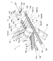
- FIG. 1 is a plan view showing a waist panel and a deployable disposable diaper obtained by one embodiment of the present invention.
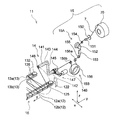
- FIG. 2 is a perspective view showing a schematic configuration of a stretchable sheet manufacturing apparatus suitably used for carrying out the manufacturing method of one embodiment (first embodiment) of the present invention.
- FIG. 3 is a perspective view showing a configuration upstream of the rotary arm (elastic body winding means) of the apparatus shown in FIG.
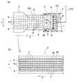
- FIG. 4A is a bird's-eye view of a part of the apparatus shown in FIG. 2, and
- FIG. 4B is a plan view showing an example of a stretchable sheet manufactured by the apparatus.
- FIG. 5 is a view showing an integration means suitably used for carrying out the manufacturing method of another embodiment (second embodiment) of the present invention.
- FIG. 6 (a) and 6 (b) are diagrams showing a schematic configuration of an apparatus for manufacturing an elastic sheet that is preferably used for carrying out the manufacturing method of another embodiment (third embodiment) of the present invention.
- FIG. 7 is a diagram showing a schematic configuration of a stretchable sheet manufacturing apparatus suitably used for carrying out the manufacturing method of another embodiment (fourth embodiment) of the present invention.
- the present invention forms a portion where the bonding strength between sheets and the fixing strength of the thread-like elastic body to the sheet are different from each other, and the expansion and contraction that can efficiently improve the prevention of slipping out of the thread-like elastic body, flexibility, appearance, etc. It is related with providing the manufacturing method of an adhesive sheet.
- the manufacturing method of the elastic sheet of this invention is demonstrated, referring drawings based on the preferable embodiment.
- the stretchable sheet manufactured in the first embodiment is used for, for example, the waist panel 3 of the unfolded disposable diaper 1. Therefore, first, the unfoldable disposable diaper 1 using the elastic sheet manufactured according to the first embodiment for the waist panel 3 will be described.
- the diaper 1 includes a ventral side A located on the abdomen side of the wearer at the time of wearing, a dorsal side B positioned on the dorsal side, and between the ventral side A and the back side B. It has the absorptive main body 2 which has the crotch part C located, and a pair of left and right waist panels 3 and 3 connected to both left and right outer sides of the back side part B. As shown in FIG. 1, the diaper 1 has a pair of left and right panel members 4, 4 connected to the left and right outer sides of the ventral side A. In the state where the diaper 1 is expanded in a planar shape as shown in FIG.
- the absorbent main body 2 is rectangular, the panel material 4 is trapezoidal, and the long side (lower bottom) side of the trapezoidal panel material 4 is It fixes to the absorptive main body 2 by well-known joining means, such as adhesives, such as a hot-melt-adhesive, and heat sealing
- the direction indicated by X is the width direction of the diaper 1 (absorbent body 2)
- the direction indicated by Y is the longitudinal direction of the diaper 1 (absorbent body 2)
- both directions X and Y are orthogonal to each other. is doing.
- the absorbent main body 2 includes a liquid-permeable top sheet 21, a liquid-impermeable or water-repellent back sheet 22, and a liquid retaining property disposed between these sheets 21 and 22.
- the absorber 23 is provided.
- the top sheet 21 forms a skin facing surface of the diaper 1 (absorbent body 2)
- the back sheet 22 forms a non-skin facing surface of the diaper 1 (absorbent body 2).
- Each of the top sheet 21 and the back sheet 22 has a rectangular shape in plan view having an outer dimension larger than that of the absorber 23, and extends outward from the peripheral edge of the absorber 23. Or joined together with other members.
- the skin-facing surface is a surface directed toward the wearer's skin when worn in the disposable diaper or its constituent members, and the non-skin facing surface is the wearer's skin side when worn in the disposable diapers or its constituent members. The surface is directed to the opposite side.
- a pair of three-dimensional guard forming sheets 24, 24 are arranged over substantially the entire length in the longitudinal direction Y of the absorbent main body 2 on both left and right side portions along the longitudinal direction Y of the absorbent main body 2.
- Each solid guard forming sheet 24 has one side edge (outer edge) along the longitudinal direction Y fixed to the absorbent main body 2 (surface sheet 21), and the other side edge (inner edge) absorbed. It is not fixed to the main body 2 but is a free edge, and one or more thread-like elastic members 25 are fixed to the other edge in a state of being extended in the longitudinal direction Y.
- the pair of three-dimensional guard forming sheets 24, 24 are separated from the surface sheet 21 by the contraction force of the elastic member 25 at the other side edge portion of the crotch part C.
- a pair of solid guards are formed.
- thread-like elastic members 26 for forming leg gathers are arranged in an extended state at portions (leg portions) arranged around the wearer's legs in the left and right sides along the longitudinal direction Y of the absorbent main body 2.
- a pair of leg gathers are formed by contraction of the elastic member 26, and the leg fits well.
- Each of the pair of waist panels 3 and 3 is an elastic sheet in which a plurality of thread-like elastic bodies 7 are bonded and fixed between two sheets 5 and 6 as shown in FIG. In the state expanded to a flat shape as shown in FIG. A plurality of thread-like elastic bodies 7 in each waist panel 3 are arranged at a predetermined interval in the longitudinal direction Y, and are fixed between the sheets 5 and 6 in a state of being extended in the width direction X.
- the waist panel 3 is located on the side opposite to the outer side portion 3A in the width direction X, and the outer side portion 3A to which the fastening tape 8 is fixed by a known joining means such as hot melt adhesive or fusion.
- the waist panel 3 has a known inner side part 3C such as a hot melt adhesive or a fusion bond to the absorbent main body 2 (specifically, for example, between the three-dimensional guard forming sheet 24 and the back sheet 22). It is fixed by the joining means.
- the waist panel 3 has a plurality of center joints 10 at the center in the width direction (X direction) and a pair of end joints 9 and 9 on both sides of the center in the width direction.
- the end joint portion 9 is formed in a strip shape having a predetermined width on each of the outer side portion 3A and the inner side portion 3C of the waist panel 3, and the central joint portion 10 is linear on the stretchable portion 3B.
- the end joint portion 9 and the center joint portion 10 are portions where the sheets 5 and 6 are joined by an adhesive, preferably a hot melt adhesive, respectively.
- the sheets 5 and 6 are continuous over the entire length in the longitudinal direction Y.
- the plurality of thread-like elastic bodies 7 are arranged from the end joint portion 9 of the outer side portion 3A to the end joint portion 9 of the inner side portion 3C, and a pair of end joint portions 9, 9 and a portion overlapping each of the plurality of central joint portions 10 therebetween.
- the thread-like elastic body 7 is fixed in a state of being sandwiched between the two sheets 5 and 6 via an adhesive at a portion overlapping the end joint 9 and the center joint 10.
- those thread-like elastic bodies 7 are fixed between the sheets 5 and 6 via the adhesive.
- each of the end joint portion 9 and the central joint portion 10 the sheets 5 and 6 are directly joined to each other via an adhesive at a portion that does not overlap the thread-like elastic body 7.
- the thread-like elastic body 7 and one or both of the two sheets 5 and 6 sandwiching the elastic body 7 are joined with an adhesive.
- the width W1 of the end joint 9 is larger than the width W2 of the center joint 10, and the end joint 9 is center joined. It is wider than the part 10.
- the end joint portion 9 and the center joint portion 10 are described so that they can be clearly recognized from the outside, but this is not always the case. .
- the end joint 9 and the center joint 10 in the waist panel 3 are formed at a predetermined interval in the width direction X, and between the adjacent end joint 9 and the center joint 10 and the adjacent center. Between the joint portions 10 is a non-adhesive region where no adhesive is disposed between the sheets 5 and 6. In these non-bonded regions, the thread-like elastic body 7 is not fixed to the sheets 5 and 6. In the waist panel 3 expanded in a planar shape, the thread-like elastic body 7 is in an extended state in the stretchable part 3B, and outward (in the direction in which the fastening tape 8 protrudes) from the end joint part 9 in the outer side part 3A.
- end side joint portion 9 in the inner side portion 3 ⁇ / b> C is in a relaxed state (non-stretched state) inward (inward in the width direction of the diaper). Further, the end of the longitudinal direction of the thread-like elastic body 7 or the vicinity thereof is fixed to the end joint 9 in an extended state.
- this type of stretchable sheet is used to join each member.
- the adhesive is preferably a hot melt type (hot melt adhesive).
- each part in the diaper 1 is demonstrated.
- various types conventionally used in the technical field can be used.
- various liquid-permeable sheet materials such as a nonwoven fabric and an apertured film can be used.
- various liquid impervious materials such as a resin film having no moisture permeability, a resin film having fine pores and moisture permeability, a nonwoven fabric such as a water-repellent nonwoven fabric, and a laminate of these and other sheets. Or water repellent materials can be used.
- a fiber aggregate such as pulp fiber or a non-woven fabric or an absorbent core formed by holding particles of a water-absorbing polymer can be used, and the absorbent core is made of water-permeable thin paper or non-woven fabric. What was coat
- seat can also be used.
- the three-dimensional guard forming sheet 24 constituting the three-dimensional guard a stretchable film, a nonwoven fabric, a woven fabric, or a laminated sheet thereof can be used.
- the panel material 4 what can be used as the sheet
- the sheets 5 and 6 constituting the waist panel 3 for example, non-woven fabrics, woven fabrics, knitted fabrics, papers, resin films by various manufacturing methods such as air-through nonwoven fabrics, heat roll nonwoven fabrics, spunlace nonwoven fabrics, spunbond nonwoven fabrics, and meltblown nonwoven fabrics. Etc., and a sheet material obtained by laminating and integrating these two or more can be used.
- the fastening tape 8 for example, a tape obtained by attaching a hook member of a mechanical fastener to one surface of a tape base material such as a nonwoven fabric by heat fusion, an adhesive, or the like can be used.
- Examples of the elastic member 25 constituting the three-dimensional guard and the elastic member 26 for forming leg gathers include natural rubber, polyurethane, polystyrene-polyisoprene copolymer, polystyrene-polybutadiene copolymer, ethyl acrylate-ethylene.
- a thread-like stretchable material made of a polyethylene- ⁇ -olefin copolymer such as the above can be used.
- the thread-like elastic body and elastic member according to the present invention include not only those having a circular or square cross section, but also those having a narrow band shape such as an ellipse or a rectangular cross section, and also those of a multifilament type.
- variety (or diameter) of the thread-like elastic body which concerns on this invention is 0.1 mm or more and 3 mm or less, for example, Preferably it is 1 mm or less.
- variety (or diameter) of an elastic member is 0.1 mm or more and 5 mm or less, for example, Preferably they are 0.1 mm or more and 3 mm or less.
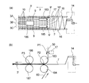
- the manufacturing apparatus 11 is an apparatus that continuously manufactures a strip-shaped stretchable sheet 3 ′ that is a raw fabric of the waist panel 3 (stretchable sheet).
- the conveyance means 16 and the rotation means (elastic body winding means) 14 for elastic body winding which winds the thread-like elastic body 7 in a continuously extended state are provided on the conveyance means 16.
- the conveying means 16 includes a pair of conveying belts 12 and 13 spaced apart in a direction (CD; Cross-machine Direction) orthogonal to the conveying direction (MD; Machine-Direction) of the belt-like sheets 50, 60, and is elastic in the form of a thread.
- the body 7 is wound around the pair of conveyor belts 12 and 13 by the rotating arm 14 in an extended state in a direction crossing the conveyance direction y.
- the belt-like sheets 50 and 60 are original sheets of the sheets 5 and 6 constituting the waist panel 3.
- the direction indicated by the symbol y (y direction) indicates the conveyance direction (MD) of the belt-like sheets 50 and 60
- the direction indicated by the symbol x (x direction) indicates CD.
- the y direction (MD) coincides with the conveyance direction of the thread-like elastic body 7 wound around the conveyance means 16 (conveyance belts 12 and 13) and the conveyance direction of the stretchable sheet 3 ′, and further, the diaper 1 (absorbent body). This also coincides with the longitudinal direction Y of 2) (see FIG. 1).
- the x direction (CD) coincides with the width direction of the belt-like sheets 50 and 60, and further coincides with the width direction X (see FIG. 1) of the diaper 1 (absorbent body 2).
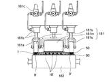
- a direction (z direction) indicated by a symbol z in FIG. 3 indicates a direction in which the pair of nip rolls 181 and 182 of the integration unit 18 face each other.
- the manufacturing apparatus 11 continuously feeds the thread-like elastic body 7 and introduces the thread-like elastic body 7 into a rotating arm (elastic body winding means) 14 in an expanded state.
- the coating device 17 provided, the integration means 18 for fixing the stretched elastic fiber 7 between the pair of strip sheets 50, 60 using the pair of nip rolls 181, 182, and the conveying direction of the strip sheets 50, 60
- a cutting hand that cuts the thread-like elastic body 7 extending outward from both ends along the (y direction) and releases the wound state of the thread-like elastic body 7 around the transport means 16 (transport belts 12 and 13). It is and a 19.
- the conveying belt 12 of the conveying means 16 is an endless rotating belt, and includes an upper belt 12a and a lower belt 12b.
- the upper belt 12a is stretched between two pulleys whose rotation axis direction is arranged in the z direction, one of which is a pulley 122 arranged on the upstream side of the integration means 18, The other one is a pulley 121 arranged on the downstream side of the integration means 18.
- the lower belt 12b is stretched between two other pulleys whose rotation axis direction is arranged in the z direction, one of which is upstream of the integration means 18 and below the pulley 122.
- the other is a pulley 124 arranged below the pulley 121 on which the upper belt 12a is bridged on the downstream side of the integration means 18.
- Each pulley is arranged outside the end along the conveyance direction (y direction) of the belt-like sheets 50 and 60.
- Servo motors (not shown) are connected to the pulleys 121 and 124 on the downstream side, and the rotation speeds of the upper belt 12a and the lower belt 12b can be changed by the servo motors.
- the conveying belt 13 of the conveying means 16 is also an endless rotating belt like the conveying belt 12, and is composed of an upper belt 13a and a lower belt 13b in two upper and lower stages as shown in FIG.
- the conveyor belt 13 is configured in the same manner as the conveyor belt 12, and the belts 13 a and 13 b are respectively two pulleys 132 and 131 or pulleys 135 arranged on the upstream side and the downstream side with the integration unit 18 interposed therebetween. , 134.
- Each of the upper belt 13a and the lower belt 13b can be driven and changed in rotational speed by the same mechanism as the upper and lower belts 12a and 12b of the conveyor belt 12.
- the conveyor belt 12 (upper belt 12a, lower belt 12b) and the conveyor belt 13 (upper belt 13a, lower belt 13b) are respectively stretched over the pulleys, thereby a pair of nip rolls 181 and 182 (integrating means 18). ) From the upstream side to the downstream side. As shown in FIG. 2, the belts 12 and 13 are located outside the end portions along the conveying direction (y direction) of the belt-like sheets 50 and 60 and are arranged symmetrically with respect to each other. Both belts 12 and 13 rotate so that their outer peripheral sides move in the y direction. Both belts 12 and 13 are preferably timing belts.
- the rotational speeds of the belts 12 and 13, that is, the rotational speed of a servo motor (not shown) disposed in a drive unit of a downstream pulley (not shown) is controlled by a control unit (not shown) provided in the manufacturing apparatus 11. ).
- the rotary arm (elastic body winding means) 14 includes an arm portion 141 having a shaft portion 142, a circumferential portion 143, and a connecting portion 144, and a center line of the shaft portion 142 as a rotation axis. And a drive mechanism 147 that rotates the arm portion 141.
- the connecting portion 144 is coupled to each of the shaft portion 142 and the rotating portion 143 at an angle, and the rotating portion 143 and the shaft portion 142 are substantially parallel.
- the shaft portion 142 has an introduction port 145 for the thread-like elastic body 7 at one end thereof, and the rotating portion 143 has a lead-out port 146 for the thread-like elastic body 7 at one end thereof.
- the thread-like elastic body 7 introduced from the introduction port 145 is smoothly led out from the lead-out port 146 through the shaft portion 142, the connecting portion 144, and the rotating portion 143.
- Various known members a driven roll, a low friction member, etc. that can reduce friction with the thread-like elastic body 7 can be disposed in the bent portion of the arm portion 141, the outlet port 146, and the like.
- the circulating portion 143 is arranged such that the outlet 146 is located downstream of the upstream end of the transport belt 12 (upper belt 12a, lower belt 12b) and the transport belt 13 (upper belt 13a, lower belt 13b). ing.
- a servo motor 148 is attached to the drive portion (shaft portion 142) of the rotary arm 14 (elastic body winding means), and the rotating portion 143 is moved to both sides by the rotation of the servo motor 148. Circulate around the outer periphery of the belt 12,13. The diameter of the locus along which the outlet 146 rotates is greater than the distance between the outer surfaces of the pair of conveyor belts 12 and 13.
- the thread-like elastic body 7 taken in can be continuously wound around the upstream end portions of the belts 12 and 13 and the outer peripheral sides thereof.
- the rotation speed of the rotary arm 14, that is, the rotation speed of the servo motor 148 is controlled by a control unit (not shown) included in the manufacturing apparatus 11.
- the elastic body supply means 15 includes a roll body 70 around which the thread-like elastic body 7 is wound, a tensor 151 that is positioned downstream of the roll body 70 and applies tension to the thread-like elastic body 7 by a brake, A feeding roll 152 is provided on the downstream side of the tensor 151 to feed the thread-like elastic body 7 from the roll body 70, and a tension measuring device 153 is provided on the downstream side of the feeding roll 152 for measuring the tension.
- the rotation axis of the feeding roll 152 is arranged in the x direction (direction perpendicular to the sheet conveyance direction).
- a servo motor (not shown) is attached to the driving unit of the feeding roll 152.
- the feeding roll 152 is used with the thread-like elastic body 7 wound twice around the outer periphery thereof.
- a control unit (not shown) provided in the manufacturing apparatus 11 controls the rotational speed of a servo motor (not shown), that is, the rotational speed of the feeding roll 152, based on the detection output from the tension measuring device 153. 7 can be unwound from the roll body 70.
- the elastic body supply means 15 includes a feed roll 156 located on the downstream side of the feeding roll 152 as shown in FIG.
- the feed roll 156 is arranged between the rotary arm (elastic body winding means) 14 and the feeding roll 152, and the rotation axis direction thereof is arranged in the x direction.
- the feed roll 156 has a servo motor (not shown) attached to its drive unit.
- the rotational speed of a servo motor (not shown), that is, the rotational speed of the feed roll 156 is controlled by a control unit (not shown) provided in the manufacturing apparatus 11.
- the coating device 17 includes a coating unit 172 that applies an adhesive to the belt-like sheet 50.
- the application means 172 is supplied with an adhesive from a storage tank of an adhesive (not shown) via a predetermined supply path.
- the application unit 172 discharges an adhesive 10 ′ (adhesive for forming the central joint) for forming the central joint 10 on the stretchable sheet 3 ′.
- a discharge port F that discharges an adhesive 9 ′ (adhesive for forming an end joint) for forming the end joint 9 in the stretchable sheet 3 ′.
- the discharge port E is provided at a position facing the central portion in the width direction of the belt-like sheet 50
- the discharge port F is provided at a position facing both ends near both ends of the central portion in the width direction of the belt-like sheet 50. ing.
- the discharge port E and the discharge port F are connected to the same common storage tank (not shown) and the supply path 173, and the same type of adhesive is connected to both the discharge ports E. , F and applied to the belt-like sheet 50.
- a known adhesive coating means can be used, and a contact-type coating means in which the coating head of the coating means contacts the surface to be coated may be used, and the coating head of the coating means does not contact the surface to be coated.
- Mold application means may be used.
- the contact coating means include a slot coater, a gravure coater, and a rotary screen coater.
- the non-contact type application means include a spray coater, a bead coater, and a curtain coater.
- tube, a flexible tube, etc. can be used as a supply path.
- the integration unit 18 includes a pair of nip rolls 181 and 182.
- the pair of nip rolls 181 and 182 are located between the inner peripheral side of the transport belt 12 (upper belt 12a and lower belt 12b) and the inner peripheral side of the transport belt 13 (upper belt 13a and lower belt 13b).
- one nip roll 181 has a small diameter portion M having a relatively small diameter at the center in the axial direction.
- One having large diameter portions S, S having relatively large diameters at both ends in the axial length direction is used.
- the other nip roll 182 has a constant diameter over the entire width of the belt-like sheets 50 and 60.
- the small diameter portion M of the nip roll 181 pressurizes a portion of the belt-like sheets 50 and 60 where the adhesive 10 ′ for forming the central joint portion is interposed therebetween, thereby increasing the size of the nip roll 181.
- the diameter portions S and S are formed so as to pressurize the portions of the belt-like sheets 50 and 60 where the adhesives 9 ′ and 9 ′ for forming end joint portions are interposed therebetween.
- nip roll 182 a cylindrical roll made of metal or a cylindrical roll made of low hardness silicon rubber can be used.
- nip roll 181 a nip roll having the same configuration as that of the nip roll 182 can be used except that the nip roll 181 has a cylindrical shape having a step on the peripheral surface.
- the pair of nip rolls 181 and 182 has a servo motor (not shown) attached to one of the drive units, and the rotation speed is controlled by a control unit (not shown) included in the manufacturing apparatus 11.
- Drive transmission gears are attached to the respective rotation shafts of the pair of nip rolls 181 and 182.
- the rotation speed of a servo motor (not shown), that is, the rotation speed of one of the pair of nip rolls 181 and 182 can be controlled based on the production speed of the stretchable sheet.
- the drive transmission gear is engaged, the driving force is transmitted to the other of the pair of nip rolls 181 and 182, and the pair of nip rolls 181 and 182 can be rotated.
- the bearing portions of the pair of nip rolls 181 and 182 use forces such as hydraulic pressure, pneumatic pressure, and spring to securely fix the stretched thread-like elastic body 7 between the pair of belt-like sheets 50 and 60. Each bearing part is pressurized.
- the cutting means 19 includes a cutter 190 in which a portion to which the conveyed elastic thread 7 hits is a sharp cutting blade.
- the cutter 190 is arranged at a position where the thread-like elastic body 7 hits by a support body (not shown), and the thread-like elastic body 7 is cut by being conveyed by the conveyor belts 12 and 13 and being pressed against the cutter 190.
- the position of the cutting means 19 is slightly downstream of the part where the thread-like elastic body 7 and the belt-like sheets 50 and 60 are integrated by the pair of nip rolls 181 and 182.
- various known devices that can cut the thread-like elastic body 7 can be used without any particular limitation.
- a cutter roll having a cutting blade extending in the circumferential direction on the outer peripheral surface and the cutting blade are received.
- a roll cutter equipped with an anvil roll can be used, and a cutting means capable of cutting the thread-like elastic body 7 with a laser or heat may be used.
- the manufacturing apparatus 11 having such a configuration is used to manufacture the waist panel 3 and the elastic sheet 3 ′ that is a continuous body of the waist panel 3 as follows.
- the thread-like elastic body 7 is continuously fed out, and the fed-out thread-like elastic body 7 is introduced into a rotating arm 14 as an elastic body winding means in an expanded state (supplying step). . More specifically, the thread-like elastic body 7 is continuously fed out from the winding roll 70 around which the thread-like elastic body 7 is wound using the feeding roll 152. At the time of unwinding, the rotational speed of the unwinding roll 152 is adjusted by a control unit (not shown) provided in the manufacturing apparatus 11 based on the detection output of the tension of the filamentous elastic body 7 by the tension measuring device 153, and a predetermined tension is applied. Then, the thread-like elastic body 7 is unwound from the winding roll 70.
- a control unit not shown
- the thread-like elastic body 7 is introduced into the rotating arm 14.
- the speed of the thread-like elastic body 7 introduced into the rotating arm 14 (elastic body winding means) by the feed roll 156 described above. Is adjusted to a constant speed and introduced.
- the introduction speed is set to a speed according to the winding speed wound around the transport means 16 (the pair of transport belts 12 and 13).
- the thread-like elastic body 7 is transferred to the conveying means 16 (the pair of conveying belts 12 and 13) using the rotary arm 14 (elastic winding means), and the belt-like sheets 50 and 60.
- the wound elastic body 7 is wound in a stretched direction in a direction intersecting with the transport direction (y direction) of the sheet, and the wound thread-like elastic body 7 is transported between the pair of belt-like sheets 50 and 60 by the transport means 16 (transport process). More specifically, as shown in FIG. 3, the thread-like elastic body 7 supplied into the rotating arm 14 in the extended state is introduced into the arm portion 141 through the introduction port 145, and the shaft portion 142, the connecting portion 144, and the rotating portion.
- the thread-like elastic body 7 immediately after being wound around the transport means 16 forms a winding length in a direction crossing the y direction (sheet transport direction). However, it does not extend in the direction orthogonal to the y direction (x direction).
- the rotational speed of the upper belt 12a may be made slower than the rotational speed of the lower belt 12b, and in the conveying belt 13, the rotational speed of the lower belt 13b may be made slower than the rotational speed of the upper belt 13a.
- the inclination (extension direction) of the thread-like elastic body 7 can be gradually changed during the conveyance in the y direction.
- the slant of the thread-like elastic body 7 can be corrected from the direction different from the original x direction to the x direction before being conveyed between the belt-like sheets 50 and 60 (between the pair of nip rolls 181 and 182). it can.
- the belt-like sheets 50 and 60 are both side portions (both ends in the x direction) along the conveying direction (y direction) by the sailor or the like (not shown) before applying the adhesive. It is folded back (on the side opposite to the surface facing the other belt-like sheet to be joined). And as shown to Fig.4 (a), for application
- the adhesive 10 ′ is applied such that a plurality of narrow-line adhesive application portions are formed in a continuous linear shape along the conveying direction of the sheet 50.
- the adhesive 9 ′ is applied so that two strip-shaped adhesive application portions are formed in a continuous linear shape along the conveying direction of the sheet 50.
- the composite sheet 30A (elastic sheet 3 ′) is obtained by applying pressure integrally (integration step). More specifically, the stretched thread-like elastic body 7 continuously wound around the transport means 16 (the pair of transport belts 12 and 13) is supplied between the pair of nip rolls 181 and 182, and the pair of belt-like sheets 50 is supplied. , 60 are supplied and merged so as to oppose the thread-like elastic body 7 being conveyed. The two sheets 50 and 60 are joined together so that the thread-like elastic body 7 is fixed therebetween, and the sheet-like elastic body 7 is sandwiched and fixed between the two sheets 50 and 60 and introduced into the pair of nip rolls 181 and 182. Pressure.
- the thread-like elastic body 7 in an elongated state extending outward from the side edge along the conveyance direction (y direction) of the composite sheet 30A is cut to shrink the thread-like elastic body 7, Cut end portions generated by cutting the thread-like elastic body 7 are present on one side portion and the other side portion along the y direction of the composite sheet 30A (cutting step). More specifically, along the conveyance direction (y direction) of the composite sheet 30A (the pair of belt-like sheets 50, 60) in the thread-like elastic body 7 that is stretched between the pair of conveyance belts 12, 13. The portions extending from both side edges (both edges of the composite sheet 30A in the x direction) are cut by the above-described cutter 190.
- the winding state of the thread-like elastic body 7 around the pair of conveying belts 12 and 13 (conveying means 16) is released, and the belt-like stretchable sheet 3 ′ is formed on the belt-like sheets 50 and 60. Both sides along the y-direction (both ends in the x-direction) are obtained in a state of being folded back to the outer surface side.
- the belt-like sheets 50 and 60 constituting the belt-like stretchable sheet 3 ′ are not folded using a sailor or the like (not shown), as shown in FIG. A belt-like stretchable sheet 3 ′ is obtained.
- the band-shaped stretchable sheet 3 ′ thus obtained is cut into a predetermined unit length (product length) by a known cutting means (not shown) to obtain the intended waist panel 3 (stretchable sheet). .
- the adhesive 9 ′ for the end joint portion is interposed between the large-diameter portions S, S of the nip roll 181 and the nip roll 182 in the belt-like sheets 50, 60.
- the portion of the belt-like sheets 50, 60 where the adhesive 10 ′ for the central joint portion is interposed between the two is pressed.
- the adhesive 9 ′ for the end joint portion generates clearance between the peripheral surface of the large diameter portion S and the peripheral surface of the nip roll 182 (between the peripheral surfaces).
- the adhesive 10 ′ for forming the central joint portion is pressed between the peripheral surface of the small-diameter portion M and the peripheral surface of the nip roll 182 (the distance) is relatively strongly pressed at a relatively narrow portion. Between perimeters Are relatively weakly pressed at a relatively wide portion. That is, the bonding conditions in the integration step between the pair of belt-like sheets differ between the adhesive 10 ′ for forming the central joint and the adhesive 9 ′ for forming the end joint. In detail, the pressure which pressurizes adhesive agent 9 'for edge part junction parts is stronger compared with the pressure which pressurizes adhesive agent 10' for center junction part formation.
- the end joints 9 and 9 are formed in the composite sheet 30A and the stretchable sheet 3 ′ by strongly joining the belt-like sheets 50 and 60 via the end joint adhesive 9 ′.
- the thread-like elastic body 7 is relatively strongly fixed as compared with the center joint part 10, and the thread-like elastic body 7 can be prevented from coming off.
- the central joint is formed by joining the belt-like sheets 50 and 60 via the adhesive 10 ′ for forming the central joint. 10 is formed, but the adhesive 10 ′ forming the central joint 10 is pressed more weakly than the adhesive 9 ′ forming the end joint 9, so that the adhesive 10 ′ is crushed.
- the region of the central joint portion 10 in the composite sheet 30A and the stretchable sheet 3 ′ is excellent in air permeability and excellent in flexibility.
- the elastic sheet 3 is less likely to come out of the thread-like elastic body 7 from the end joints 9 and 9 and is excellent in air permeability, flexibility and stretchability between the end joints 9 and 9. 'And the waist panel 3 can be manufactured efficiently.
- the central joint 10 is formed by pressing the adhesive 10 ′ relatively weakly as compared with the end joint 9, so that the central joint 10 has a gap between the belt-like sheets 50 and 60.
- the center joint 10 is formed between the pair of end joints 9, although the joints are relatively weaker than the end joints 9 and the thread-like elastic body 7 is fixed relatively weakly. For this reason, in the central joint portion 10, problems such as separation between the sheets 50 and 60 and removal of the thread-like elastic body 7 are unlikely to occur.
- the width W1 (see FIG. 1) of the end joint 9 is preferably 3 mm or more, more preferably 5 mm or more, from the viewpoint of secure fixing of the end of the thread-like elastic body 7 or the vicinity thereof.
- it is 20 mm or less, More preferably, it is 10 mm or less, Preferably it is 3 mm or more and 20 mm or less, More preferably, it is 5 mm or more and 10 mm or less.
- the width W2 (see FIG. 1) of the central joint portion 10 is preferably 0.1 mm or more, more preferably from the viewpoint of forming the stretchable portion 10B having good air permeability and stretchability between the end joint portions 9.
- the interval W3 (see FIG. 1) between the adjacent end joints 9 and the central joint 10 and the interval W4 (see FIG. 1) between the two adjacent central joints 10 and 10 are respectively
- the thickness is preferably 1 mm or more, more preferably 3 mm or more, and preferably 10 mm or less, more preferably 7 mm or less, and preferably 1 mm or more and 10 mm or less, more preferably 3 mm or more and 7 mm or less.
- the interval W5 see FIG.
- 1) between the two thread-like elastic bodies 7 and 7 adjacent in the Y direction is preferably 2 mm or more, more preferably 4 mm or more, and preferably 12 m or less, more preferably 10 mm. In addition, it is preferably 2 mm or more and 12 mm or less, more preferably 4 mm or more and 10 mm or less.
- one roll 181 is provided with large-diameter portions S, S and small-diameter portions M to press the adhesive 10 ′ for forming the central joint, and for forming the end joint
- the pressure applied to the pair of belt-like sheets 50, 60 is different from the portion where the adhesive 9 'is pressed, the difference in diameter between the large diameter portions S, S and the small diameter portion M is the belt-like sheets 50, 60.
- the radius Rs and the small diameter of the large diameter portions S and S can be appropriately determined depending on the thickness of the large diameter portions S and S from the point of providing a sufficient pressure difference between the large diameter portions S and S and the small diameter portion M.
- the difference in radius Rm (Rs ⁇ Rm) of the part M and the difference in clearance between the large diameter parts S, S and the small diameter part M are preferably 0.01 mm or more, for example, 0.01 mm or more and 1 mm or less. More preferably.
- the diaper 1 provided with the waist panel 3 can be manufactured by the following method, for example. That is, the fastening tape 8 is intermittently fixed to the stretchable sheet 3 ′ obtained as described above, and then cut into the size of each diaper, or the stretchable sheet 3 ′ is sized for each diaper.
- the waist panel 3 as shown in FIG. 1 is obtained by fixing the fastening tape 8 after cutting into a size. In the manufacture of the waist panel 3, it is preferable to obtain a pair of left and right waist panels 3, 3 having different fastening tape 8 mounting positions from the two stretchable sheets 3 '.
- the continuous body of the top sheet 21 is continuously transported, and the continuous body of the three-dimensional guard forming sheet 24 is joined to each of both sides in the transport direction to obtain a composite continuous sheet. . Then, while continuously conveying the composite continuous sheet, a pair of left and right waist panels 3, 3 obtained from the two stretchable sheets 3 'is provided with an interval in the flow direction of the composite continuous sheet with respect to both sides thereof. And fix it sequentially. And the continuous body of the back surface sheet 22 is merged and integrated so that the absorbers 23, 23.
- a plurality of elastic members 25 and a panel material 34 in an extended state are arranged on both sides of the absorber 23, and they are also continuous between the continuous body of the three-dimensional guard forming sheet 24 and the back sheet 22. Fix between the body.
- a continuous body of diapers 1 is manufactured in which a plurality of pairs of waist panels 3 are fixed to both sides of the continuous body of the absorbent main body 2.
- the conveyance direction (y direction) of the continuous body of the absorbent main body 2 and the conveyance direction (y direction) when manufacturing the waist panel 3 (elastic sheet) are the same direction, and the waist panel 3 (extension and contraction). It is not necessary to invert the adhesive sheet) by 90 °.
- many diapers 1 can be manufactured one by one by cutting the continuous body of diapers 1 into the size of each diaper 1 by a known cutting means (not shown).
- a pair of band-like sheets 50 and 60 are used in an integration process in which the pair of belt-like sheets 50 and 60 are integrally pressed with the thread-like elastic body 7 sandwiched therebetween.
- the rolls 181 and 182 one in which at least one roll 181 is composed of a plurality of short rolls 181 s, 181 m and 181 s arranged in the width direction (x direction) of the pair of belt-like sheets 50 and 60 is used.
- the adhesive 10 'for forming a central joint similar to the central joint in the form is applied, and a plurality of the belt-like sheets 50 and 60 are sandwiched between the thread-like elastic bodies 7 therebetween.
- the pressure is applied between a roll 181 composed of a short roll and a roll 182 that is not divided into a plurality of short rolls.
- the short rolls 181s and 181s are arranged at positions overlapping the application position of the adhesive 9 ′ for forming the end joint in the width direction of the belt-like sheets 50 and 60, and the short roll 181m is used for forming the central joint. It arrange
- the short rolls 181 s, 181 m, 181 s are arranged at the same position in the flow direction (y direction) of the belt-like sheets 50, 60, and each roll has a common single roll 182. It faces the peripheral surface.
- the short rolls 181s, 181m, and 181s in the illustrated example are respectively a shaft support 181a that supports a rotating shaft, a lifting mechanism 181b that vertically displaces the shaft support 181a, and a pressure gauge 181c that measures the pressure applied by the roll. It has.
- the elevating mechanism 181b various known ones such as a hydraulic cylinder, an air cylinder, and a screw jack can be used.
- the short rolls 181 s and 181 s that pressurize the adhesive 9 ′ for forming the end joint portion are a pair of strips rather than the short roll 181 m that presses the adhesive 10 ′ for forming the central joint portion.
- the thread-like elastic body 7 and the belt-like sheets 50 and 60 are integrated while maintaining or controlling the sheets 50 and 60 to be more strongly pressurized.
- the clearance between the short rolls 181s, 181s and the roll 182 is set to be narrower than the clearance between the short roll 181m and the roll 182, and the value of each clearance is fixed, and the thread-like elastic body 7 and
- the belt-like sheets 50 and 60 may be pressurized, or the pressure applied by the short roll 181s and the pressure applied by the short roll 181m are monitored, and the pressure difference is constantly maintained within a certain range.
- the thread-like elastic body 7 and the belt-like sheets 50 and 60 may be pressurized while moving the roll up and down.
- Various known automatic control devices can be used for monitoring pressure and maintaining pressure by raising and lowering the short roll.
- the joining conditions in the integration step between the pair of belt-like sheets are different between the adhesive 10 ′ for forming the central joint and the adhesive 9 ′ for forming the end joint. . More specifically, the pressure of pressing when joining a pair of belt-like sheets via an adhesive is varied. That is, according to the manufacturing method of the second embodiment, between the short rolls 181 s, 181 s and the nip roll 182, the portion of the belt-like sheets 50, 60 where the adhesive 9 ′ for the end joint portion is interposed therebetween.
- the portion of the belt-like sheets 50, 60 where the adhesive 10 ′ for the central joint is interposed is relatively weakly pressed between the short roll 181 m and the nip roll 182. Is done. Thereby, like the first embodiment, the thread-like elastic body 7 is unlikely to come off from the end joints 9 and 9, and the end joints 9 and 9 are excellent in air permeability, flexibility and stretchability.
- the stretchable sheet 3 ′ and the waist panel 3 can be efficiently manufactured.
- FIG.6 (a) and FIG.6 (b) As the manufacturing apparatus of elastic sheet 3 ', one side of elastic sheet 3' to manufacture is shown.
- a sheet provided downstream of each of the first rolls 183 and 184 and the second rolls 185 and 184 in the conveyance direction (y direction) of the sheets 50 and 60 is used.
- the adhesive agent 9 'for forming the edge part junction part 9 and the center junction part 10 are formed in the single side
- the belt-like sheet 50 and the other belt-like sheet 60 are joined together so that the thread-like elastic body 7 is sandwiched between the two sheets 50 and 60.
- part in which adhesive part 9 ', 9' for edge part junction formation interposes between a pair of 1st rolls 183,184 or a pair of 2nd rolls 185. 184 and pressurizing.
- the bonding conditions in the integration step between the pair of belt-like sheets are different between the adhesive 10 ′ for forming the central bonded portion and the adhesive 9 ′ for forming the edge bonded portion. .
- the adhesive 9 ′ and the adhesive 10 ′ for forming the central joint are applied.
- the adhesive 9 ′ is applied by the first and second rolls.
- the time until pressing is different from the time from applying the adhesive 10 ′ to the belt-like sheet 50 until pressing with the third roll.
- the adhesive 9 'for forming the end joint is applied and then the adhesive 9' is pressed with the first and second rolls. Is shorter than the time from application of the adhesive 10 ′ for forming the central joint portion to pressing of the adhesive 10 ′ between the third rolls. For this reason, when the temperature and type when applied to the belt-like sheet 50, the basis weight to be applied, etc. are the same, the adhesive 9 'is higher in temperature than the adhesive 10', that is, in a state where the viscosity is low. , 60 together with pressure.
- the end joint 9 where the sheets 50 and 60 are joined by the adhesive 9 ′ is more suitable for the sheets 50 and 60 than the central joint 10 where the sheets 50 and 60 are joined by the adhesive 10 ′.
- the bonding strength between the yarns and the fixing strength of the thread-like elastic body to the sheets 50 and 60 are relatively high.
- the adhesive 10 ′ having a lower temperature that is, having a higher viscosity
- the air permeability and stretchability are reduced by the adhesive 10 ′. Hard to occur.
- the thread-like elastic body 7 is unlikely to come off from the end joints 9 and 9, and the gap between the end joints 9 and 9 is air permeable, flexible, and stretchable.
- the elastic sheet 3 ′ and the waist panel 3 excellent in the above can be efficiently manufactured.
- the adhesive 10 ' is pressed with a roll from the coating position P1 of the adhesive 10' to the distance (L1) from the coating position P1 of the adhesive 9 'to the position P2 where the adhesive 9' is pressed with a roll.
- the ratio (L2 / L1) of the distance (L2) to the position P3 is preferably 1.1 or more, more preferably 1.2 or more, preferably 5 or less, more preferably 2 or less, , Preferably 1.1 or more and 5 or less, more preferably 1.2 or more and 2 or less.
- the distances L1 and L2 are measured along the transport path of the belt-like sheet on which each adhesive is applied.
- one roll 183 of the 1st rolls 183 and 184 and one roll 185 of the 2nd rolls 185 and 184 are shown in FIG.
- the other roll 184 of the first rolls 183 and 184 and the other roll 184 of the second rolls 185 and 184 are separated from each other in the belt-like sheet 50, A single cylindrical roll having a uniform diameter over substantially the entire width of 60.
- separate rolls spaced in the x direction may be used as the first roll 184 and the second roll 184.
- both rolls may have a common rotating shaft, or both rolls are independent of each other. And you may have a rotating shaft.
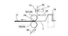
- an apparatus for manufacturing the stretchable sheet 3 ′ shown in FIG. 7 is used.
- the stretch sheet 3 ′ shown in FIG. 7 has a substantially full width of the belt-like sheets 50, 60 as the integrated means 18 for fixing the stretched thread-like elastic body 7 between the pair of belt-like sheets 50, 60, respectively.
- an adhesive 9 ′ for forming an end joint and an adhesive 10 ′ for forming a central joint are applied to the belt-like sheet 50.
- a cooling means 20 for cooling the adhesive is provided between the coating device 17 to be worked and the portion P4 where the belt-like sheets 50 and 60 are pressed by the pair of nip rolls 181 ′ and 182.
- the configuration of the coating device 17 is the same as that of the coating device 17 shown in FIG.
- the cooling means 20 cools only the adhesive 10 ′ of the adhesive 9 ′ and the adhesive 10 ′, or cools the adhesive 10 ′ more strongly than the adhesive 9 ′.
- a cool air device that cools the adhesive by blowing cool air, a contact type chill roll (cooling roll), or the like can be used.
- a cold air device is preferred because it is advantageous.
- the bonding conditions in the integration step between the pair of belt-like sheets are made different between the adhesive 10 ′ for forming the central bonded portion and the adhesive 9 ′ for forming the edge bonded portion. .
- the adhesive 10 ' is cooled by the cooling means 20, and the temperature of the adhesive 10' is lowered.
- the adhesive 9 ′ is not cooled substantially or the degree of cooling is weakened, and the temperature is higher than that of the adhesive 10 ′.
- the belt-like sheet 50 and the other belt-like sheet 60 are joined together so as to sandwich the thread-like elastic body 7 between the two sheets 50 and 60, and then sandwiched between the pair of rolls 181 'and 182. Pressurize.
- the adhesive 9 ′ is pressed together with the sheets 50 and 60 in a state where the temperature is higher than that of the adhesive 10 ′. Therefore, the adhesive between the sheets 50 and 60 is joined with the adhesive 10 ′ by using an adhesive having a kind and temperature range in which a high joining strength can be obtained due to a lower viscosity than a lower one at a higher temperature.
- the end joint 9 in which the sheets 50 and 60 are joined with the adhesive 9 ′ is stronger than the central joint 10 that is made with respect to the joint strength between the sheets 50 and 60 and the sheets 50 and 60 of the filamentous elastic body. Fixing strength is relatively high.
- the adhesive 10 ′ having a lower temperature that is, having a higher viscosity
- the thread-like elastic body 7 is unlikely to come off from the end joints 9 and 9 and the space between the end joints 9 and 9 is air permeable, flexible and stretchable.
- the elastic sheet 3 ′ and the waist panel 3 excellent in the above can be efficiently manufactured.
- the planar view shape of the pair of waist panels 3 and 3 is a rectangle, but may be a trapezoid or a parallelogram.
- the plan view shape of the waist panel 3 is such that when the stretchable sheet 3 ′ is cut to obtain the pair of waist panels 3 and 3, the portion to be discarded (the portion not used as the waist panel 3) is minimized. It is preferable to do.
- the thread-like elastic body 7 is wound around the pair of transport belts 12 and 13 in a stretched state in a direction intersecting without crossing the y direction (sheet transport direction) and then tilted (stretch direction). ) Is corrected in the direction orthogonal to the y direction (x direction), but it may be fixed to the pair of belt-like sheets 50 and 60 without correcting the angle around the conveyor belts 12 and 13.
- the elastic body winding means includes a disk having a thread-like elastic body introducing portion at the rotating shaft portion and an arm protruding downstream from the disk in the y direction. It is also possible to use one that wraps around the belt and winds the elastic thread around the conveyor belts 12 and 13. Also, as the feed roll 156, as shown in FIG. 3, instead of feeding a material (thread-like elastic body) and feeding the material, a feed roll 156 sandwiching the material with a material may be used. it can.
- a conveyor belt as disclosed in WO2005 / 060910 may be used instead of a pair of conveyor belts.
- a thread support member provided with a screw groove described in FIGS. 4 to 6 of JP-A No. 2002-192641 may be used.
- the end joint is applied to the one strip 50.
- the adhesive 9 ′ for forming the portion may be applied, and the adhesive 10 ′ for forming the central joint portion may be applied to the other belt-shaped sheet 60.
- the adhesive 9 'that forms one end joint may be applied to one belt-like sheet, and the adhesive 9' that forms the other end joint may be applied to the other belt-like sheet.
- an adhesive 10 ′ for forming a part of the plurality of central joints is applied to one belt-like sheet, and an adhesive 10 ′ for forming the other part is applied to the other belt-like sheet. You may apply to.
- the positions of the roll that presses the adhesive 9 ′ for forming the end joint and the roll that presses the adhesive 10 ′ for forming the central joint are shifted in the y direction.
- the adhesive 10 ′ for forming the central joint with the third roll is used instead of pressurizing only the adhesive 10 ′ for forming the central joint with the third roll. You may pressurize both adhesives 9 'for end part junction formation.
- the cooling means 20 is applied.
- the adhesive 10 ' is cooled by the above, but after the adhesive 9' and the adhesive 10 'are applied, the adhesive 9' may be heated without cooling the adhesive 10 ', or the adhesive 10' It is also possible to perform cooling and heating of the adhesive 9 '.
- an end joint 9 having a higher adhesive strength between the sheets 50 and 60 and a higher fixing strength of the thread-like elastic body 7 than the central joint 10
- the adhesive strength between the sheets 50 and 60 and the fixing strength of the thread-like elastic body 7 may be lower than that of the central joint 10.
- the end joint 9 in this case is used, for example, to suppress the movement of the cut end accompanying the contraction of the thread-like elastic body immediately after cutting, and to correct irregular arrangement of the cut end of the thread-like elastic body. Can do.
- the pair of rolls used in the integration process may be both rolls driven by rotating in contact with the belt-like sheet without being driven to rotate.
- the stretchable sheet produced according to the present invention may have only one central joint at the center in the width direction instead of one having a plurality of center joints at the center in the width direction.
- the central joint is preferably wider than the width of each of the end joints on both sides thereof, and more preferably wider than the total width of the end joints on both sides.
- the central joint portion and the end joint portions on both sides thereof may be adjacent or continuous without interposing a non-adhesive region.
- the magnitude of the joining strength of the center joining portion and the end joining portion in the stretchable sheet is, for example, the dimension (length) in the direction corresponding to the transport direction (MD) during manufacture and the transport direction (MD) from each joint portion.
- a test piece having the same dimension (width) in the direction corresponding to the direction (CD) orthogonal to the direction (CD) is obtained, and a peel test (such as a 90 ° peel test) is performed on the test pieces to peel the sheets in the longitudinal direction It can be judged by performing etc.
- the test piece has a length of 65 mm and a width of 30 mm, for example, and the width of the test piece is smaller than the width of the joint of the narrower one when the width of the narrower part is less than 30 mm.
- the pressure for pressurizing the adhesive 9 ′ for the end joint is stronger than the pressure for pressurizing the adhesive 10 ′ for forming the central joint,
- the adhesive 10 'for forming the central joint may be pressed more strongly.
- the time until the adhesive 9 ′ is pressed with the first and second rolls after the adhesive 9 ′ for forming the end joint is applied to the center joint is formed. Although the time from applying the adhesive 10 ′ to pressing the adhesive 10 ′ between the third rolls is shortened, the time until pressing the adhesive 10 ′ for forming the central joint is increased. May be shortened.
- the adhesive 9 ′ for forming the end joint 9 maintains a higher temperature than the adhesive 10 ′ for forming the central joint 10, and the sheet Although the pressure is applied together with 50 and 60, the pressure may be applied in a state where the temperature of the adhesive 10 ′ for forming the central joint 10 is higher. By doing so, the fixing strength of the thread-like elastic body 7 is increased at the central joint portion 10, and the contraction force of the thread-like elastic body 7 bonded and fixed in an extended state is less likely to affect the end joint portion 9.
- the thread-like elastic body 7 is hard to come off and looks good, and the stretchable sheet 3 ′ and the waist panel 3 which are excellent in stretchability and flexible can be efficiently manufactured.
- the stretchable sheet produced by the production method of the present invention includes a waist part of a developed or pant-type disposable diaper, a waist part of a pant-type disposable diaper, and a pant-type sanitary garment. It can also be used for napkins, disposable underwear, disposable mask ear hooks, cleaning sheets, bandages and the like.
- a method for producing a stretchable sheet for continuously producing a stretchable sheet having a pair of end joints on both sides of the central portion in the width direction Using the elastic body winding means, the thread-like elastic body is wound around the thread-like elastic body conveying means so as to extend in a direction crossing the conveying direction, and the wound thread-like elastic body is A conveying step of conveying in the conveying direction by the conveying means; An adhesive application step of applying an adhesive to one or both of the pair of belt-like sheets; The pair of belt-like sheets after the adhesive application step are joined to the thread-like elastic body transported by the transport means, and the pair of belt-like sheets sandwiching the thread-like elastic body are integrally pressed to An integration process for obtaining a stretchable sheet, A method for producing a stretchable sheet, wherein a bonding condition in the integration step between a pair of the belt-like sheets is made different between the adhesive for forming the central joint portion and the adhesive for forming the end joint portion.
- a pair of the belt-like sheets are introduced and pressed between a pair of rolls, and a portion for pressing the adhesive for forming the central joint portion as the pair of rolls, and the end
- ⁇ 3> The production of the elastic sheet according to ⁇ 2>, wherein the pressure for pressurizing the adhesive for forming the end joint is stronger than the pressure for pressurizing the adhesive for forming the central joint.
- the diameter of the portion that pressurizes the adhesive for forming the end joint portion is larger than the diameter of the portion that pressurizes the adhesive for forming the central joint portion.
- At least one of the pair of rolls includes a plurality of short rolls arranged in the width direction of the pair of belt-like sheets, and the plurality of short rolls pressurize the adhesive for forming the end joint portion.
- the short roll is configured to press the pair of belt-like sheets more strongly than the short roll that presses the adhesive for forming the central joint portion.
- ⁇ 6> A difference (Rs ⁇ Rm) between a radius Rs of a portion where the adhesive for forming the end joint portion is pressed and a radius Rm of the portion where the adhesive for forming the central joint is pressed in the roll.
- the difference in clearance between the portion for pressurizing the adhesive for forming the end joint and the portion for pressurizing the adhesive for forming the central joint is preferably 0.01 mm or more, and 0.01 mm or more and 1 mm More preferably, the method for producing a stretchable sheet according to any one of the above items ⁇ 1> to ⁇ 5>.
- the pressure which pressurizes the adhesive for ⁇ 7> said edge part junction part is a manufacturing method of the elastic sheet as described in said ⁇ 2> weak compared with the pressure which pressurizes the adhesive agent for said center junction part formation.
- the pair of the belt-like sheets are introduced and pressed between the pair of rolls, and the adhesive for forming the central joint portion is applied to one or both of the pair of the belt-like sheets.
- a time from when the adhesive is pressed between the pair of rolls to a time from when the adhesive for forming the end joint is applied to when the adhesive is pressed between the pair of rolls.
- the method for producing a stretchable sheet according to ⁇ 8> wherein the time until the adhesive is pressed between a pair of rolls is short.
- a pair of rolls that pressurize the adhesive for the central joint is provided downstream in the conveying direction of the pair of belt-like sheets, rather than a pair of rolls that pressurize the adhesive for the end joints.
- ⁇ 11> Forming the central joint with respect to the distance (L1) from the application position P1 of the adhesive for the end joint to the position P2 where the adhesive for the end joint is pressed with a roll.
- the ratio (L2 / L1) of the distance (L2) from the adhesive application position P1 to the position P3 where the adhesive for forming the central joint is pressed with a roll is preferably 1.1 or more, more preferably Is 1.2 or more, preferably 5 or less, more preferably 2 or less, and preferably 1.1 or more and 5 or less, more preferably 1.2 or more and 2 or less, ⁇ 8>
- One of the pair of rolls that pressurizes one of the end joints, and one of the pair of rolls that presses the other of the end joints conveys the belt-like sheet.
- the other roll of the pair of rolls that pressurizes one of the end joints, and the other roll of the pair of rolls that pressurizes the other of the end joints The method for producing an elastic sheet according to the above ⁇ 12>, which is a common cylindrical roll having a uniform diameter over substantially the entire width.
- One of the pair of rolls that pressurizes one of the end joints, and one of the pair of rolls that presses the other of the end joints conveys the belt-like sheet.
- the time from pressing the adhesive between the pair of rolls is applied.
- the adhesive for the central joint or the adhesive for the end joint is cooled or heated, and in the integration step, between the pair of belt-like sheets, The method for producing a stretchable sheet according to ⁇ 1>, wherein the pair of belt-like sheets are pressed between a pair of rolls in a state where the two adhesives having different temperatures due to cooling or heating are interposed.
- the adhesive for the end joint is heated between the pair of rolls together with the pair of belt-like sheets in a state where the temperature is higher than the adhesive for the center joint.
- the method for producing an elastic sheet according to ⁇ 17> wherein the elastic sheet is pressed.
- the adhesive for forming the end joint After applying the adhesive for forming the end joint and the adhesive for forming the central joint on one surface of the belt-like sheet, the adhesive for forming the end joint is heated ⁇ The manufacturing method of the elastic sheet of 17> or ⁇ 18> description. ⁇ 20> After coating the adhesive for forming the end joint and the adhesive for forming the central joint on one side of the belt-like sheet, the adhesive for forming the central joint is cooled. ⁇ 17>- ⁇ 19> The method for producing an elastic sheet according to any one of ⁇ 19>. ⁇ 21> In the integration step, the adhesive for the central joint is heated between the pair of rolls together with the pair of belt-like sheets in a state where the temperature is higher than the adhesive for the end joint. The method for producing an elastic sheet according to ⁇ 17>, wherein the elastic sheet is pressed.
- the width W1 of the end joint is preferably 3 mm or more, more preferably 5 mm or more, preferably 20 mm or less, more preferably 10 mm or less, and preferably 3 mm or more and 20 mm or less.
- the method for producing a stretchable sheet according to any one of the above items ⁇ 1> to ⁇ 22> which is 5 mm or more and 10 mm or less.
- the width W2 of the central joint is preferably 0.1 mm or more, more preferably 0.5 mm or more, preferably 5 mm or less, more preferably 1.5 mm or less, and preferably The method for producing a stretchable sheet according to any one of the above items ⁇ 1> to ⁇ 23>, which is 0.1 mm to 5 mm, more preferably 0.5 mm to 1.5 mm.
- the interval W3 between the adjacent end joint and the central joint is preferably 1 mm or more, more preferably 3 mm or more, and preferably 10 mm or less, more preferably 7 mm or less.
- the elastic sheet has a plurality of the central joint portions,
- the interval W4 between the two adjacent central joints is preferably 1 mm or more, more preferably 3 mm or more, preferably 10 mm or less, more preferably 7 mm or less, and preferably 1 mm or more and 10 mm or less.
- the method for producing an elastic sheet according to any one of the above items ⁇ 1> to ⁇ 25> which is 3 mm or more and 7 mm or less.
- the interval W5 between the two filamentous elastic bodies adjacent to each other in the longitudinal direction of the stretchable sheet is preferably 2 mm or more, more preferably 4 mm or more, and preferably 12 m or less, more preferably 10 mm or less.
- ⁇ 30> The above-mentioned ⁇ 1> to ⁇ 29>, wherein the end joint part is formed with higher adhesive strength between the pair of belt-like sheets and fixing strength of the thread-like elastic body than the central joint part.
- ⁇ 31> The above-mentioned ⁇ 1> to ⁇ 29>, wherein the end joint is formed with a lower adhesive strength between the pair of belt-like sheets and a fixing strength of the thread-like elastic body than the central joint.
- One of the nip rolls has a small diameter portion M having a relatively small diameter at the central portion in the axial length direction, and large diameter portions S and S having relatively large diameters at both end portions in the axial length direction.
- the small-diameter portion M pressurizes a portion of the belt-like sheet where an adhesive for forming a central joint portion is interposed therebetween, and the large-diameter portions S and S are end-joint members of the belt-like sheet.
- the method for producing an elastic sheet according to ⁇ 32> wherein the part is formed so as to pressurize a portion where an adhesive for forming a portion is interposed.
- One nip roll and the other nip roll as the pair of nip rolls The method for producing an elastic sheet according to any one of ⁇ 32> to ⁇ 33>, wherein the other nip roll has a constant diameter over the entire width of the belt-like sheet.
- ⁇ 35> The method for producing a stretchable sheet according to any one of ⁇ 1> to ⁇ 34>, wherein the stretchable sheet has a plurality of central joint portions at a central portion in the width direction.
- ⁇ 36> The method for producing a stretchable sheet according to any one of ⁇ 1> to ⁇ 35>, wherein the stretchable sheet has only one central joint at the center in the width direction.
- ⁇ 37> The method for producing a stretchable sheet according to ⁇ 36>, wherein the center joint portion is wider than a width of each of the end joint portions.
- the ⁇ 38> above-mentioned center junction part is a manufacturing method of the elastic sheet as described in said ⁇ 36> or ⁇ 37> which is wider than the total width of a pair of said edge part junction part.
- An absorptive main body having an abdominal side located on the abdomen side of the wearer at the time of wearing, a dorsal side located on the dorsal side, and a crotch part located between the abdomen and the back side; A pair of left and right waist panels connected to the left and right sides of the side, A disposable diaper using an elastic sheet obtained by the method for producing an elastic sheet according to any one of ⁇ 1> to ⁇ 39> for the waist panel.
- the method for producing a stretchable sheet of the present invention it is possible to efficiently form portions where the bonding strength between the sheets and the fixing strength of the threadlike elastic body are different from each other, thereby preventing the threadlike elastic body from coming off in the stretchable sheet. Can improve efficiency, flexibility, appearance, and the like efficiently.
- a stretchable sheet it is possible to efficiently produce a stretchable sheet that is less likely to lose the thread-like elastic body from the end joint portion and that has excellent breathability, flexibility, and stretchability between the end joint portions. it can.
Abstract
A method for producing a stretchable sheet comprises a step of applying adhesives (9', 10') to one or both of a pair of belt-shaped sheets (50, 60), and an integration step of joining the belt-shaped sheets (50, 60) with a thread-shaped elastic body (7) conveyed by a conveyance means (16), and integrally pressurizing the belt-shaped sheets with the thread-shaped elastic body (7) interposed therebetween to obtain a stretchable sheet (30A), and the condition for joining in the integration step between the pair of belt-shaped sheets (50, 60) is made different between the adhesive (9') for forming a central joint and the adhesive (10') for forming an end joint. For example, the pair of belt-shaped sheets (50, 60) is introduced between a pair of rolls (181, 182) and pressurized, and a roll having different pressures to be applied to the pair of belt-shaped sheets (50, 60) in a portion for pressurizing the adhesive (10') for forming the central joint and a portion for pressurizing the adhesive (9') for forming the end joint is used for the pair of rolls.
Description
本発明は、伸縮性シートの製造方法に関する。
The present invention relates to a method for producing an elastic sheet.
従来、表面シート、裏面シート及びこれら両シート間に介在配置された吸収体を備えた実質的に縦長の吸収性本体と、該吸収性本体の本体長手方向に沿う両側縁部に設けられた一対のウエストパネルとを有し、一対の該ウエストパネルそれぞれの本体長手方向に沿う外側縁部に固定されたファスニングテープの止着部を、該吸収性本体の非肌対向面の被止着領域に止着して着用者に装着するようになされている、いわゆる展開型のパネルタイプの使い捨ておむつが知られている。このウエストパネルとしては、装着性等の観点から、伸縮性を有するシート状部材(伸縮性シート)が用いられている。
Conventionally, a substantially vertically long absorbent body provided with a top sheet, a back sheet, and an absorbent body disposed between both sheets, and a pair provided on both side edges along the longitudinal direction of the absorbent body. A fastening portion of a fastening tape fixed to an outer edge along the longitudinal direction of the main body of each of the pair of waist panels, and a non-skin-facing surface of the absorbent main body, 2. Description of the Related Art A so-called unfolded panel type disposable diaper that is adapted to be worn and worn by a wearer is known. As this waist panel, a sheet-like member (elastic sheet) having elasticity is used from the viewpoint of wearability and the like.
例えば特許文献1には、ウエストパネルに伸縮性シートを用いた展開型のパネルタイプの使い捨ておむつとして、2枚のシートの間に複数本の糸状弾性体を伸長状態で接着固定して構成された伸縮性シートをウエストパネル(止着テープ)として用いたテープ式使い捨ておむつが記載されている。特許文献1に記載の止着テープにおいて、2枚のシートは、幅方向(前記本体長手方向と直交する方向)に所定の間隔を空けて形成された、止着テープの上端から下端まで連続する縦縞状の接着部分により接着されている。
また、特許文献1には、特許文献1のウエストパネル(止着テープ)の製造方法として、長さ方向に搬送中のシートに縦縞状に接着剤を塗布した後、該シートを、一対の搬送ベルトに螺旋状に巻き掛けられることによって該シートの搬送方向と略直交する方向に引っ張られて伸長状態とされた糸状弾性体と合流させて接合した後に、別のシートを、前記のシートとの間に前記糸状弾性体を挟むように合流させ、それらを一対のロール間で一体的に加圧し一体化させることが記載されている。 For example,Patent Document 1 is configured as an unfolded panel-type disposable diaper using a stretchable sheet for a waist panel, and a plurality of thread-like elastic bodies are bonded and fixed between two sheets in an expanded state. A tape-type disposable diaper using an elastic sheet as a waist panel (fastening tape) is described. In the fastening tape described in Patent Document 1, the two sheets are continuously formed from the upper end to the lower end of the fastening tape formed at a predetermined interval in the width direction (direction perpendicular to the longitudinal direction of the main body). Bonded by vertically striped bonded portions.
Further, inPatent Document 1, as a method of manufacturing a waist panel (fastening tape) of Patent Document 1, an adhesive is applied to a sheet being transported in the length direction in a vertical stripe shape, and then the sheet is transported to a pair. After joining the thread-like elastic body that has been stretched by being wound around the belt in a spiral shape and pulled in a direction substantially perpendicular to the conveying direction of the sheet, another sheet is bonded to the sheet. It is described that the thread-like elastic bodies are joined so as to be sandwiched therebetween, and they are integrally pressed and integrated between a pair of rolls.
また、特許文献1には、特許文献1のウエストパネル(止着テープ)の製造方法として、長さ方向に搬送中のシートに縦縞状に接着剤を塗布した後、該シートを、一対の搬送ベルトに螺旋状に巻き掛けられることによって該シートの搬送方向と略直交する方向に引っ張られて伸長状態とされた糸状弾性体と合流させて接合した後に、別のシートを、前記のシートとの間に前記糸状弾性体を挟むように合流させ、それらを一対のロール間で一体的に加圧し一体化させることが記載されている。 For example,
Further, in
しかし、糸状弾性体を挟んだ2枚のシートを一対のロール間で加圧する際に、縦縞状に塗工した接着剤が強く加圧されると、細帯状に塗布された接着剤が潰れてシートの幅方向に広がることによって、伸縮性シートの通気性や柔軟性が低下する。他方、通気性や柔軟性を考慮して低い圧力で加圧した場合には、伸長状態において糸状弾性体を固定した接着部分から該糸状弾性体が抜け易くなる。
However, when two sheets sandwiching the thread-like elastic body are pressed between a pair of rolls, if the adhesive applied in the form of vertical stripes is pressed strongly, the adhesive applied in the form of a strip is crushed. By spreading in the width direction of the sheet, the breathability and flexibility of the stretchable sheet are lowered. On the other hand, when pressure is applied at a low pressure in consideration of air permeability and flexibility, the thread-like elastic body is easily removed from the bonded portion where the thread-like elastic body is fixed in the extended state.
また、特許文献1に記載の伸縮性シート(止着テープ)においては、その製造時に搬送ベルトに伸長状態で巻き掛けられた糸状弾性体の両端部を切断することによって生じた、該糸状弾性体の端部(切断端部)が、該糸状弾性体の切断後の収縮によって個々ばらばらに不規則な方向を向いてしまう場合があり、これらの不規則な切断端部により、伸縮性シートの見栄えが悪くなるおそれがある。
Further, in the stretchable sheet (fastening tape) described in Patent Document 1, the thread-like elastic body produced by cutting both ends of the thread-like elastic body wound around the conveyor belt in the stretched state at the time of manufacture. End portions (cut end portions) of the thread-like elastic body may be individually oriented in irregular directions due to shrinkage after the cut of the thread-like elastic body. May get worse.
このような、糸状弾性体の端部(切断端部)の不規則な並びを解消する方法として、伸縮性シートを構成するシートにおける切断端部が存する部位(伸縮性シートの製造時におけるシートの搬送方向に沿う端部)に、切断端部が形成される前(糸状弾性体の切断工程前)に予め接着剤を塗布しておき、該接着剤によって、切断直後の糸状弾性体の収縮に伴う切断端部の動きを抑制する方法が考えられる。しかし、この方法により所定の効果(糸状弾性体の切断端部の不規則な並びの是正)を得るためには、切断端部のシートに対する固定強度を適切に制御する必要がある。
As a method for eliminating the irregular arrangement of the end portions (cut end portions) of the thread-like elastic body, a portion where the cut end portions exist in the sheet constituting the stretchable sheet (the sheet at the time of production of the stretchable sheet). An adhesive is applied in advance to the end along the conveying direction) before the cutting end is formed (before the cutting process of the thread-like elastic body), and the adhesive causes the thread-like elastic body to contract immediately after cutting. A conceivable method is to suppress the movement of the associated cutting edge. However, in order to obtain a predetermined effect (correction of irregular arrangement of the cut end portions of the thread-like elastic body) by this method, it is necessary to appropriately control the fixing strength of the cut end portions with respect to the sheet.
本発明は、一対の帯状シートの間に糸状弾性体を該帯状シートの搬送方向と交差する方向に伸長した状態に接着固定した伸縮性シートであり、その幅方向中央部に中央接合部を有すると共に該幅方向中央部の両側に一対の端部接合部を有する伸縮性シートを連続的に製造する伸縮性シートの製造方法に関する。
本発明の伸縮性シートの製造方法は、弾性体巻回手段を用いて前記糸状弾性体を、該糸状弾性体の搬送手段に、前記搬送方向と交差する方向に伸長した状態となるように巻回し、巻回された該糸状弾性体を該搬送手段により前記搬送方向に搬送する搬送工程と、一対の前記帯状シートの一方又は双方に接着剤を塗布する接着剤塗布工程と、前記接着剤塗布工程後の一対の前記帯状シートを、前記搬送手段により搬送されている前記糸状弾性体に合流させ、該糸状弾性体を挟んだ一対の該帯状シートを一体的に加圧して前記伸縮性シートを得る一体化工程とを具備する。 The present invention is an elastic sheet in which a thread-like elastic body is bonded and fixed in a state extending in a direction crossing the conveying direction of the belt-like sheet between a pair of belt-like sheets, and has a central joint portion in the center in the width direction. And it is related with the manufacturing method of the elastic sheet which manufactures the elastic sheet which has a pair of edge part junction part on both sides of this width direction center part continuously.
In the elastic sheet manufacturing method of the present invention, the elastic thread winding means is used to wind the thread-like elastic body so that the thread-like elastic body is stretched in a direction intersecting the transport direction. A conveying step of conveying the wound and wound elastic elastic body in the conveying direction by the conveying means; an adhesive applying step of applying an adhesive to one or both of the pair of belt-like sheets; and the adhesive application The pair of band-like sheets after the process are joined to the thread-like elastic body conveyed by the conveying means, and the pair of band-like sheets sandwiching the thread-like elastic body are pressed together to form the stretchable sheet. Integration step to obtain.
そして、本発明の伸縮性シートの製造方法においては、一対の前記帯状シート間の前記一体化工程における接合の条件を、前記中央接合部形成用の接着剤と前記端部接合部形成用の接着剤とで異ならせる。
And in the manufacturing method of the stretchable sheet of the present invention, the bonding condition in the integration step between the pair of strip-shaped sheets is the adhesive for forming the central joint and the adhesive for forming the end joint. Different depending on the agent.
本発明の好ましい実施態様においては、前記一体化工程において、一対の前記帯状シートを一対のロール間に導入して加圧すると共に、一対の該ロールとして、前記中央接合部形成用の接着剤を加圧する部分と、前記端部接合部形成用の接着剤を加圧する部分とで、一対の前記帯状シートに加える圧力が異なるように構成したものを用いる。
In a preferred embodiment of the present invention, in the integration step, the pair of belt-like sheets are introduced and pressed between the pair of rolls, and an adhesive for forming the central joint is added as the pair of rolls. What is configured so that the pressure applied to the pair of belt-like sheets is different between the portion to be pressed and the portion to which the adhesive for forming the end joint portion is pressed.
また、本発明の他の好ましい実施態様においては、前記一体化工程において、一対の前記帯状シートを一対のロール間に導入して加圧すると共に、一対の帯状シートの一方又は双方に前記中央接合部形成用の接着剤を塗工してから該接着剤を一対のロール間で加圧するまでの時間と、前記端部接合部形成用の接着剤を塗工してから該接着剤を一対のロール間で加圧するまでの時間とを異ならせる。
In another preferred embodiment of the present invention, in the integration step, the pair of belt-like sheets are introduced and pressed between a pair of rolls, and the center joint portion is attached to one or both of the pair of belt-like sheets. The time from application of the forming adhesive to the pressurization of the adhesive between the pair of rolls, and the application of the adhesive for forming the end joints, the adhesive to the pair of rolls Different time between pressurization.
また、本発明の更に他の好ましい実施態様においては、前記接着剤塗布工程後に、前記中央接合部用の接着剤又は前記端部接合部用の接着剤の冷却又は加熱を行い、前記一体化工程において、一対の前記帯状シート間に、冷却又は加熱により温度が異なる状態の前記両接着剤を介在させた状態で、一対の該帯状シートを一対のロール間で加圧する。
In still another preferred embodiment of the present invention, after the adhesive application step, the adhesive for the central joint portion or the adhesive for the end joint portion is cooled or heated to perform the integration step. The pair of belt-like sheets are pressed between a pair of rolls in a state where the two adhesives having different temperatures due to cooling or heating are interposed between the pair of belt-like sheets.
本発明における伸縮性シートは、好ましくは、一対の帯状シートの間に糸状弾性体を該帯状シートの搬送方向と交差する方向に伸長した状態に接着固定した伸縮性シートであり、その幅方向中央部に中央接合部を有すると共に該幅方向中央部の両側に一対の端部接合部を有する。
The stretchable sheet in the present invention is preferably a stretchable sheet in which a thread-like elastic body is bonded and fixed in a state extending in a direction intersecting the transport direction of the strip-like sheet between a pair of strip-like sheets, and the center in the width direction thereof. The center portion has a central joint portion and a pair of end joint portions on both sides of the widthwise central portion.
また、本発明は、装着時に装着者の腹側に位置する腹側部、背側に位置する背側部、及び腹側部と背側部との間に位置する股下部を有する吸収性本体と、背側部の左右両外方に連設された左右一対のウエストパネルとを有し、前記ウエストパネルに、前記の伸縮性シートの製造方法で得られた伸縮性シートを用いた使い捨ておむつを提供するものである。
The present invention also provides an absorptive main body having an abdominal part located on the abdomen side of the wearer at the time of wearing, a dorsal part located on the dorsal side, and a crotch part located between the abdomen and back side parts And a pair of left and right waist panels connected to the left and right outer sides of the back side portion, and the waist panel is a disposable diaper using the elastic sheet obtained by the method for manufacturing the elastic sheet Is to provide.
本発明は、シート間の接合強度や糸状弾性体のシートに対する固定強度が相互に異なる部位を形成して、糸状弾性体の抜け防止性、柔軟性、見栄え等を効率よく向上させることのできる伸縮性シートの製造方法を提供することに関する。
The present invention forms a portion where the bonding strength between sheets and the fixing strength of the thread-like elastic body to the sheet are different from each other, and the expansion and contraction that can efficiently improve the prevention of slipping out of the thread-like elastic body, flexibility, appearance, etc. It is related with providing the manufacturing method of an adhesive sheet.
以下、本発明の伸縮性シートの製造方法を、その好ましい実施態様に基づき図面を参照しながら説明する。
第1実施態様で製造する伸縮性シートは、図1に示すように、例えば展開型の使い捨ておむつ1のウエストパネル3に用いられる。従って、先ず、第1実施態様により製造される伸縮性シートをウエストパネル3に用いた展開型の使い捨ておむつ1について説明する。 Hereinafter, the manufacturing method of the elastic sheet of this invention is demonstrated, referring drawings based on the preferable embodiment.
As shown in FIG. 1, the stretchable sheet manufactured in the first embodiment is used for, for example, thewaist panel 3 of the unfolded disposable diaper 1. Therefore, first, the unfoldable disposable diaper 1 using the elastic sheet manufactured according to the first embodiment for the waist panel 3 will be described.
第1実施態様で製造する伸縮性シートは、図1に示すように、例えば展開型の使い捨ておむつ1のウエストパネル3に用いられる。従って、先ず、第1実施態様により製造される伸縮性シートをウエストパネル3に用いた展開型の使い捨ておむつ1について説明する。 Hereinafter, the manufacturing method of the elastic sheet of this invention is demonstrated, referring drawings based on the preferable embodiment.
As shown in FIG. 1, the stretchable sheet manufactured in the first embodiment is used for, for example, the
おむつ1は、図1に示すように、装着時に装着者の腹側に位置する腹側部A、背側に位置する背側部B、及び腹側部Aと背側部Bとの間に位置する股下部Cを有する吸収性本体2と、背側部Bの左右両外方に連設された左右一対のウエストパネル3,3とを有する。おむつ1は、図1に示すように、腹側部Aの左右両外方に連設された左右一対のパネル材4,4を有している。おむつ1を図1に示す如く平面状に拡げた状態において、吸収性本体2は矩形形状、パネル材4は台形形状であり、台形状のパネル材4は、その長辺(下底)側が、ホットメルト接着剤等の接着剤や熱融着等の公知の接合手段により吸収性本体2に固定されている。尚、図中、符合Xで示す方向はおむつ1(吸収性本体2)の幅方向、符合Yで示す方向はおむつ1(吸収性本体2)の長手方向であり、両方向X,Yは互いに直交している。
As shown in FIG. 1, the diaper 1 includes a ventral side A located on the abdomen side of the wearer at the time of wearing, a dorsal side B positioned on the dorsal side, and between the ventral side A and the back side B. It has the absorptive main body 2 which has the crotch part C located, and a pair of left and right waist panels 3 and 3 connected to both left and right outer sides of the back side part B. As shown in FIG. 1, the diaper 1 has a pair of left and right panel members 4, 4 connected to the left and right outer sides of the ventral side A. In the state where the diaper 1 is expanded in a planar shape as shown in FIG. 1, the absorbent main body 2 is rectangular, the panel material 4 is trapezoidal, and the long side (lower bottom) side of the trapezoidal panel material 4 is It fixes to the absorptive main body 2 by well-known joining means, such as adhesives, such as a hot-melt-adhesive, and heat sealing | fusion. In the figure, the direction indicated by X is the width direction of the diaper 1 (absorbent body 2), the direction indicated by Y is the longitudinal direction of the diaper 1 (absorbent body 2), and both directions X and Y are orthogonal to each other. is doing.
吸収性本体2は、図1に示すように、液透過性の表面シート21と、液不透過性又は撥水性の裏面シート22と、これら両シート21,22間に介在配置された液保持性の吸収体23とを有している。表面シート21は、おむつ1(吸収性本体2)の肌対向面を形成し、裏面シート22は、おむつ1(吸収性本体2)の非肌対向面を形成している。表面シート21及び裏面シート22は、それぞれ、吸収体23よりも外形寸法の大きい平面視矩形形状を有し、吸収体23の周縁部から外方に延出しており、それらの延出部において直接的に又は他の部材を介在させて互いに接合されている。尚、肌対向面は、使い捨ておむつ又はその構成部材における着用時に着用者の肌側に向けられる面であり、非肌対向面は、使い捨ておむつ又はその構成部材における着用時に着用者の肌側とは反対側に向けられる面である。
As shown in FIG. 1, the absorbent main body 2 includes a liquid-permeable top sheet 21, a liquid-impermeable or water-repellent back sheet 22, and a liquid retaining property disposed between these sheets 21 and 22. The absorber 23 is provided. The top sheet 21 forms a skin facing surface of the diaper 1 (absorbent body 2), and the back sheet 22 forms a non-skin facing surface of the diaper 1 (absorbent body 2). Each of the top sheet 21 and the back sheet 22 has a rectangular shape in plan view having an outer dimension larger than that of the absorber 23, and extends outward from the peripheral edge of the absorber 23. Or joined together with other members. The skin-facing surface is a surface directed toward the wearer's skin when worn in the disposable diaper or its constituent members, and the non-skin facing surface is the wearer's skin side when worn in the disposable diapers or its constituent members. The surface is directed to the opposite side.
図1に示すように、吸収性本体2の長手方向Yに沿う左右両側部には、一対の立体ガード形成用シート24,24が、吸収性本体2の長手方向Yの略全長に亘って配置されている。各立体ガード形成用シート24は、その長手方向Yに沿う一側縁部(外側縁部)が吸収性本体2(表面シート21)に固定され、他側縁部(内側縁部)は、吸収性本体2に固定されておらず自由縁部となっており、該他側縁部に、1本以上の糸状の弾性部材25が長手方向Yに伸長された状態で固定されている。斯かる構成により、一対の立体ガード形成用シート24,24は、おむつ1の着用時において、股下部Cにおける前記他側縁部が弾性部材25の収縮力によって表面シート21から離間し、それによって一対の立体ガードが形成される。また、吸収性本体2の長手方向Yに沿う左右両側部における着用者の脚廻りに配される部位(レッグ部)には、レッグギャザー形成用の糸状の弾性部材26が伸長状態で配されており、おむつ1の着用時には、弾性部材26の収縮により一対のレッグギャザーが形成され、脚廻りに対して良好にフィットする。
As shown in FIG. 1, a pair of three-dimensional guard forming sheets 24, 24 are arranged over substantially the entire length in the longitudinal direction Y of the absorbent main body 2 on both left and right side portions along the longitudinal direction Y of the absorbent main body 2. Has been. Each solid guard forming sheet 24 has one side edge (outer edge) along the longitudinal direction Y fixed to the absorbent main body 2 (surface sheet 21), and the other side edge (inner edge) absorbed. It is not fixed to the main body 2 but is a free edge, and one or more thread-like elastic members 25 are fixed to the other edge in a state of being extended in the longitudinal direction Y. With such a configuration, when the diaper 1 is worn, the pair of three-dimensional guard forming sheets 24, 24 are separated from the surface sheet 21 by the contraction force of the elastic member 25 at the other side edge portion of the crotch part C. A pair of solid guards are formed. In addition, thread-like elastic members 26 for forming leg gathers are arranged in an extended state at portions (leg portions) arranged around the wearer's legs in the left and right sides along the longitudinal direction Y of the absorbent main body 2. In addition, when the diaper 1 is worn, a pair of leg gathers are formed by contraction of the elastic member 26, and the leg fits well.
一対のウエストパネル3,3は、それぞれ、図1に示すように、2枚のシート5,6の間に複数本の糸状弾性体7が伸長状態で接着固定された伸縮性シートであり、図1に示す如き平面状に拡げた状態において矩形形状である。各ウエストパネル3における複数本の糸状弾性体7は、長手方向Yに所定間隔を置いて配置され、且つそれぞれ幅方向Xに伸長された状態でシート5,6間に固定されている。
ウエストパネル3は、ファスニングテープ8がホットメルト接着剤や融着等の公知の接合手段により固定されている外方側部3Aと、幅方向Xにおいて外方側部3Aとは反対側に位置する内方側部3Cとを有し、これらの両側部3A,3C間に、幅方向Xに伸縮性を有する伸縮部3Bを有している。ウエストパネル3は、その内方側部3Cにて、吸収性本体2(具体的には例えば、立体ガード形成用シート24と裏面シート22との間)にホットメルト接着剤や融着等の公知の接合手段により固定されている。 Each of the pair of waist panels 3 and 3 is an elastic sheet in which a plurality of thread-like elastic bodies 7 are bonded and fixed between two sheets 5 and 6 as shown in FIG. In the state expanded to a flat shape as shown in FIG. A plurality of thread-like elastic bodies 7 in each waist panel 3 are arranged at a predetermined interval in the longitudinal direction Y, and are fixed between the sheets 5 and 6 in a state of being extended in the width direction X.
Thewaist panel 3 is located on the side opposite to the outer side portion 3A in the width direction X, and the outer side portion 3A to which the fastening tape 8 is fixed by a known joining means such as hot melt adhesive or fusion. An inward side portion 3C is provided, and an elastic portion 3B having elasticity in the width direction X is provided between both side portions 3A and 3C. The waist panel 3 has a known inner side part 3C such as a hot melt adhesive or a fusion bond to the absorbent main body 2 (specifically, for example, between the three-dimensional guard forming sheet 24 and the back sheet 22). It is fixed by the joining means.
ウエストパネル3は、ファスニングテープ8がホットメルト接着剤や融着等の公知の接合手段により固定されている外方側部3Aと、幅方向Xにおいて外方側部3Aとは反対側に位置する内方側部3Cとを有し、これらの両側部3A,3C間に、幅方向Xに伸縮性を有する伸縮部3Bを有している。ウエストパネル3は、その内方側部3Cにて、吸収性本体2(具体的には例えば、立体ガード形成用シート24と裏面シート22との間)にホットメルト接着剤や融着等の公知の接合手段により固定されている。 Each of the pair of
The
図1に示すように、ウエストパネル3は、幅方向(X方向)の中央部に複数本の中央接合部10を有すると共に該幅方向中央部の両側に一対の端部接合部9,9を有している。端部接合部9は、ウエストパネル3の外方側部3A及び内方側部3Cのそれぞれに、所定の幅を有する帯状に形成されており、中央接合部10は、伸縮部3Bに直線状に複数本形成されている。
端部接合部9及び中央接合部10は、それぞれ、接着剤、好ましくはホットメルト接着剤によりシート5,6間が接合された部分であり、本実施態様で製造するウエストパネル3においては、図1に示すように、シート5,6(ウエストパネル3)の長手方向Yの全長に亘って連続している。
また、複数本の糸状弾性体7は、外方側部3Aの端部接合部9から内方側部3Cの端部接合部9に亘って配されており、一対の端部接合部9,9及びそれらの間の複数本の中央接合部10のそれぞれと重なる部分を有している。そして、糸状弾性体7は、端部接合部9及び中央接合部10と重なる部分においては、接着剤を介して2枚のシート5,6間に挟まれた状態に固定されている。換言すれば、端部接合部9及び中央接合部10のそれぞれにおける糸状弾性体7と重なる部分においては、それらの糸状弾性体7が、シート5,6どうし間に接着剤を介して固定されており、端部接合部9及び中央接合部10のそれぞれにおける糸状弾性体7と重ならない部分においては、シート5,6どうし間が接着剤を介して直接接合されている。端部接合部9及び中央接合部10においては、糸状弾性体7と、それを挟む2枚のシート5,6の一方又は両方との間が接着剤で接合されていることが好ましい。
なお、第1実施形態で製造するウエストパネル3においては、図1に示すように、端部接合部9の幅W1が中央接合部10の幅W2よりも大きく、端部接合部9が中央接合部10よりも幅広となっている。尚、図1では、説明容易のため、端部接合部9及び中央接合部10は、外部から明瞭に認識できるように記載しているが、実際にはそのようになっているとは限らない。 As shown in FIG. 1, thewaist panel 3 has a plurality of center joints 10 at the center in the width direction (X direction) and a pair of end joints 9 and 9 on both sides of the center in the width direction. Have. The end joint portion 9 is formed in a strip shape having a predetermined width on each of the outer side portion 3A and the inner side portion 3C of the waist panel 3, and the central joint portion 10 is linear on the stretchable portion 3B. Are formed in multiple numbers.
The endjoint portion 9 and the center joint portion 10 are portions where the sheets 5 and 6 are joined by an adhesive, preferably a hot melt adhesive, respectively. In the waist panel 3 manufactured in this embodiment, 1, the sheets 5 and 6 (waist panel 3) are continuous over the entire length in the longitudinal direction Y.
Further, the plurality of thread-likeelastic bodies 7 are arranged from the end joint portion 9 of the outer side portion 3A to the end joint portion 9 of the inner side portion 3C, and a pair of end joint portions 9, 9 and a portion overlapping each of the plurality of central joint portions 10 therebetween. The thread-like elastic body 7 is fixed in a state of being sandwiched between the two sheets 5 and 6 via an adhesive at a portion overlapping the end joint 9 and the center joint 10. In other words, in the portion overlapping with the thread-like elastic body 7 in each of the end joint portion 9 and the center joint portion 10, those thread-like elastic bodies 7 are fixed between the sheets 5 and 6 via the adhesive. In each of the end joint portion 9 and the central joint portion 10, the sheets 5 and 6 are directly joined to each other via an adhesive at a portion that does not overlap the thread-like elastic body 7. In the end joint portion 9 and the center joint portion 10, it is preferable that the thread-like elastic body 7 and one or both of the two sheets 5 and 6 sandwiching the elastic body 7 are joined with an adhesive.
In thewaist panel 3 manufactured in the first embodiment, as shown in FIG. 1, the width W1 of the end joint 9 is larger than the width W2 of the center joint 10, and the end joint 9 is center joined. It is wider than the part 10. In FIG. 1, for ease of explanation, the end joint portion 9 and the center joint portion 10 are described so that they can be clearly recognized from the outside, but this is not always the case. .
端部接合部9及び中央接合部10は、それぞれ、接着剤、好ましくはホットメルト接着剤によりシート5,6間が接合された部分であり、本実施態様で製造するウエストパネル3においては、図1に示すように、シート5,6(ウエストパネル3)の長手方向Yの全長に亘って連続している。
また、複数本の糸状弾性体7は、外方側部3Aの端部接合部9から内方側部3Cの端部接合部9に亘って配されており、一対の端部接合部9,9及びそれらの間の複数本の中央接合部10のそれぞれと重なる部分を有している。そして、糸状弾性体7は、端部接合部9及び中央接合部10と重なる部分においては、接着剤を介して2枚のシート5,6間に挟まれた状態に固定されている。換言すれば、端部接合部9及び中央接合部10のそれぞれにおける糸状弾性体7と重なる部分においては、それらの糸状弾性体7が、シート5,6どうし間に接着剤を介して固定されており、端部接合部9及び中央接合部10のそれぞれにおける糸状弾性体7と重ならない部分においては、シート5,6どうし間が接着剤を介して直接接合されている。端部接合部9及び中央接合部10においては、糸状弾性体7と、それを挟む2枚のシート5,6の一方又は両方との間が接着剤で接合されていることが好ましい。
なお、第1実施形態で製造するウエストパネル3においては、図1に示すように、端部接合部9の幅W1が中央接合部10の幅W2よりも大きく、端部接合部9が中央接合部10よりも幅広となっている。尚、図1では、説明容易のため、端部接合部9及び中央接合部10は、外部から明瞭に認識できるように記載しているが、実際にはそのようになっているとは限らない。 As shown in FIG. 1, the
The end
Further, the plurality of thread-like
In the
ウエストパネル3における端部接合部9及び中央接合部10は、幅方向Xに所定間隔を置いて形成されており、隣り合う端部接合部9と中央接合部10との間、及び隣り合う中央接合部10どうし間は、シート5,6間に接着剤が配されていない非接着領域となっている。それらの非接着領域では、糸状弾性体7はシート5,6に対して非固定状態となっている。
平面状に拡げたウエストパネル3において、糸状弾性体7は、伸縮部3Bにおいては伸長状態となっており、外方側部3Aにおける端部接合部9より外方(ファスニングテープ8が突出する方向)及び内方側部3Cにおける端部接合部9より内方(おむつの幅方向内方側)においては弛緩状態(非伸長状態)となっている。また、糸状弾性体7は、その長手方向の端部又はその近傍が、端部接合部9に伸長状態で固定されている。 Theend joint 9 and the center joint 10 in the waist panel 3 are formed at a predetermined interval in the width direction X, and between the adjacent end joint 9 and the center joint 10 and the adjacent center. Between the joint portions 10 is a non-adhesive region where no adhesive is disposed between the sheets 5 and 6. In these non-bonded regions, the thread-like elastic body 7 is not fixed to the sheets 5 and 6.
In thewaist panel 3 expanded in a planar shape, the thread-like elastic body 7 is in an extended state in the stretchable part 3B, and outward (in the direction in which the fastening tape 8 protrudes) from the end joint part 9 in the outer side part 3A. ) And the end side joint portion 9 in the inner side portion 3 </ b> C is in a relaxed state (non-stretched state) inward (inward in the width direction of the diaper). Further, the end of the longitudinal direction of the thread-like elastic body 7 or the vicinity thereof is fixed to the end joint 9 in an extended state.
平面状に拡げたウエストパネル3において、糸状弾性体7は、伸縮部3Bにおいては伸長状態となっており、外方側部3Aにおける端部接合部9より外方(ファスニングテープ8が突出する方向)及び内方側部3Cにおける端部接合部9より内方(おむつの幅方向内方側)においては弛緩状態(非伸長状態)となっている。また、糸状弾性体7は、その長手方向の端部又はその近傍が、端部接合部9に伸長状態で固定されている。 The
In the
シート5,6どうしの接着(あるいは端部接合部及び中央接合部の形成)に使用する接着剤としては、この種の伸縮性シート(ウエストパネル)において各部材間を接合するのに使用されているものを特に制限無く用いることができ、例えば、非晶性ポリオレフィン、エチレン-酢酸ビニル共重合体(EVA)、エチレン-アクリル酸エステル共重合体(EEA)、スチレンーブタジエンースチレンブロック共重合体(SBS)、スチレンーイソプレンースチレンブロック共重合体(SIS)、スチレン-エチレン/ブチレン-スチレンブロック共重合体(SEBS)、スチレン-エチレン/プロピレン-スチレンブロック共重合体(SEPS)等の熱可塑性ポリマー及びそれらの混合物等が挙げられる。前記接着剤はホットメルト型(ホットメルト接着剤)が好ましい。
As an adhesive used for bonding the sheets 5 and 6 (or forming end joints and central joints), this type of stretchable sheet (waist panel) is used to join each member. In particular, amorphous polyolefin, ethylene-vinyl acetate copolymer (EVA), ethylene-acrylic acid ester copolymer (EEA), styrene-butadiene-styrene block copolymer (SBS), styrene-isoprene-styrene block copolymer (SIS), styrene-ethylene / butylene-styrene block copolymer (SEBS), styrene-ethylene / propylene-styrene block copolymer (SEPS), etc. Examples thereof include polymers and mixtures thereof. The adhesive is preferably a hot melt type (hot melt adhesive).
おむつ1における各部の形成材料について説明する。
表面シート21及び裏面シート22としては、当該技術分野において従来用いられている各種のものを用いることができる。表面シート21としては、不織布や開孔フィルム等の各種液透過性のシート材を用いることができる。裏面シート22としては、透湿性を有しない樹脂フィルムや、微細孔を有し、透湿性を有する樹脂フィルム、撥水不織布等の不織布、これらと他のシートとのラミネート体等の各種液不透過性ないし撥水性のものを用いることができる。吸収体23としては、パルプ繊維等の繊維集合体若しくは不織布又はこれらに吸水性ポリマーの粒子を保持させてなる吸収性コアを用いることができ、該吸収性コアを透水性の薄紙や不織布からなるコアラップシートで被覆したものを用いることもできる。立体ガードを構成する立体ガード形成用シート24としては、伸縮性のフィルム、不織布、織物又はそれらの積層シート等を用いることができる。また、パネル材4としては、ウエストパネル3を構成するシート5,6として使用可能なもの(後述する)を用いることができる。 The formation material of each part in thediaper 1 is demonstrated.
As thetop sheet 21 and the back sheet 22, various types conventionally used in the technical field can be used. As the surface sheet 21, various liquid-permeable sheet materials such as a nonwoven fabric and an apertured film can be used. As the back sheet 22, various liquid impervious materials such as a resin film having no moisture permeability, a resin film having fine pores and moisture permeability, a nonwoven fabric such as a water-repellent nonwoven fabric, and a laminate of these and other sheets. Or water repellent materials can be used. As the absorbent body 23, a fiber aggregate such as pulp fiber or a non-woven fabric or an absorbent core formed by holding particles of a water-absorbing polymer can be used, and the absorbent core is made of water-permeable thin paper or non-woven fabric. What was coat | covered with the core wrap sheet | seat can also be used. As the three-dimensional guard forming sheet 24 constituting the three-dimensional guard, a stretchable film, a nonwoven fabric, a woven fabric, or a laminated sheet thereof can be used. Moreover, as the panel material 4, what can be used as the sheet | seats 5 and 6 which comprise the waist panel 3 (it mentions later) can be used.
表面シート21及び裏面シート22としては、当該技術分野において従来用いられている各種のものを用いることができる。表面シート21としては、不織布や開孔フィルム等の各種液透過性のシート材を用いることができる。裏面シート22としては、透湿性を有しない樹脂フィルムや、微細孔を有し、透湿性を有する樹脂フィルム、撥水不織布等の不織布、これらと他のシートとのラミネート体等の各種液不透過性ないし撥水性のものを用いることができる。吸収体23としては、パルプ繊維等の繊維集合体若しくは不織布又はこれらに吸水性ポリマーの粒子を保持させてなる吸収性コアを用いることができ、該吸収性コアを透水性の薄紙や不織布からなるコアラップシートで被覆したものを用いることもできる。立体ガードを構成する立体ガード形成用シート24としては、伸縮性のフィルム、不織布、織物又はそれらの積層シート等を用いることができる。また、パネル材4としては、ウエストパネル3を構成するシート5,6として使用可能なもの(後述する)を用いることができる。 The formation material of each part in the
As the
ウエストパネル3を構成するシート5,6としては、例えば、エアースルー不織布、ヒートロール不織布、スパンレース不織布、スパンボンド不織布、メルトブローン不織布等の各種製法による不織布、織布、編布、紙、樹脂フィルム等、及びこれら2以上を積層一体化させてなるシート材等を用いることができる。また、ファスニングテープ8としては、例えば、不織布等のテープ基材の一方の面上にメカニカルファスナーのフック部材を熱融着や接着剤等により貼り付けてなるもの等を用いることができる。
As the sheets 5 and 6 constituting the waist panel 3, for example, non-woven fabrics, woven fabrics, knitted fabrics, papers, resin films by various manufacturing methods such as air-through nonwoven fabrics, heat roll nonwoven fabrics, spunlace nonwoven fabrics, spunbond nonwoven fabrics, and meltblown nonwoven fabrics. Etc., and a sheet material obtained by laminating and integrating these two or more can be used. Further, as the fastening tape 8, for example, a tape obtained by attaching a hook member of a mechanical fastener to one surface of a tape base material such as a nonwoven fabric by heat fusion, an adhesive, or the like can be used.
糸状弾性体7並びに立体ガードを構成する弾性部材25及びレッグギャザー形成用の弾性部材26としては、天然ゴム、ポリウレタン、ポリスチレン-ポリイソプレン共重合体、ポリスチレン-ポリブタジエン共重合体、アクリル酸エチル-エチレン等のポリエチレン-αオレフィン共重合体等からなる糸状の伸縮性材料を用いることができる。本発明に係る糸状弾性体及び弾性部材には、断面が円形、正方形状のものの他、楕円形、断面矩形等の細幅帯状のものも含まれ、マルチフィラメントタイプのものも含まれる。本発明に係る糸状弾性体の幅(又は径)は、例えば、0.1mm以上3mm以下であり、好ましくは1mm以下である。また、弾性部材の幅(又は径)は、例えば、0.1mm以上5mm以下であり、好ましくは0.1mm以上3mm以下である。
Examples of the elastic member 25 constituting the three-dimensional guard and the elastic member 26 for forming leg gathers include natural rubber, polyurethane, polystyrene-polyisoprene copolymer, polystyrene-polybutadiene copolymer, ethyl acrylate-ethylene. A thread-like stretchable material made of a polyethylene-α-olefin copolymer such as the above can be used. The thread-like elastic body and elastic member according to the present invention include not only those having a circular or square cross section, but also those having a narrow band shape such as an ellipse or a rectangular cross section, and also those of a multifilament type. The width | variety (or diameter) of the thread-like elastic body which concerns on this invention is 0.1 mm or more and 3 mm or less, for example, Preferably it is 1 mm or less. Moreover, the width | variety (or diameter) of an elastic member is 0.1 mm or more and 5 mm or less, for example, Preferably they are 0.1 mm or more and 3 mm or less.
次に、本発明の伸縮性シートの製造方法の好ましい実施態様を、前述したおむつ1のウエストパネル3(伸縮性シート)を製造する場合を例にとり図面を参照しながら説明する。図2及び図3には、第1実施態様のウエストパネル3(伸縮性シート)の製造方法に好適に用いられる製造装置11が模式的に示されている。
Next, a preferred embodiment of the method for producing a stretchable sheet of the present invention will be described with reference to the drawings, taking as an example the case of producing the waist panel 3 (stretchable sheet) of the diaper 1 described above. 2 and 3 schematically show a manufacturing apparatus 11 that is preferably used in the method for manufacturing the waist panel 3 (elastic sheet) of the first embodiment.
製造装置11は、図2及び図3に示すように、ウエストパネル3(伸縮性シート)の原反である帯状の伸縮性シート3'を連続的に製造する装置であり、糸状弾性体7の搬送手段16と、搬送手段16に、糸状弾性体7を連続的に伸長状態で巻回する弾性体巻回用の回転アーム(弾性体巻回手段)14とを備えている。搬送手段16は、帯状シート50,60の搬送方向(MD;Machine Direction)と直交する方向(CD;Cross machine Direction)に離間した一対の搬送ベルト12,13を含んで構成されており、糸状弾性体7は、回転アーム14によって、一対の搬送ベルト12,13間を搬送方向yと交差する方向に伸長状態で巻き掛けられる。帯状シート50,60は、ウエストパネル3を構成するシート5,6の原反である。
As shown in FIGS. 2 and 3, the manufacturing apparatus 11 is an apparatus that continuously manufactures a strip-shaped stretchable sheet 3 ′ that is a raw fabric of the waist panel 3 (stretchable sheet). The conveyance means 16 and the rotation means (elastic body winding means) 14 for elastic body winding which winds the thread-like elastic body 7 in a continuously extended state are provided on the conveyance means 16. The conveying means 16 includes a pair of conveying belts 12 and 13 spaced apart in a direction (CD; Cross-machine Direction) orthogonal to the conveying direction (MD; Machine-Direction) of the belt- like sheets 50, 60, and is elastic in the form of a thread. The body 7 is wound around the pair of conveyor belts 12 and 13 by the rotating arm 14 in an extended state in a direction crossing the conveyance direction y. The belt- like sheets 50 and 60 are original sheets of the sheets 5 and 6 constituting the waist panel 3.
図2及び図3中符合yで示す方向(y方向)は、帯状シート50,60の搬送方向(MD)を示し、符号xで示す方向(x方向)はCDを示す。y方向(MD)は、搬送手段16(搬送ベルト12,13)に巻回された糸状弾性体7の搬送方向や伸縮性シート3'の搬送方向と一致し、更に、おむつ1(吸収性本体2)の長手方向Y(図1参照)とも一致する。また、x方向(CD)は、帯状シート50,60の幅方向と一致し、更に、おむつ1(吸収性本体2)の幅方向X(図1参照)とも一致する。また、図3中符合zで示す方向(z方向)は、一体化手段18の一対のニップロール181,182どうしが対向する方向を示す。
2 and 3, the direction indicated by the symbol y (y direction) indicates the conveyance direction (MD) of the belt- like sheets 50 and 60, and the direction indicated by the symbol x (x direction) indicates CD. The y direction (MD) coincides with the conveyance direction of the thread-like elastic body 7 wound around the conveyance means 16 (conveyance belts 12 and 13) and the conveyance direction of the stretchable sheet 3 ′, and further, the diaper 1 (absorbent body). This also coincides with the longitudinal direction Y of 2) (see FIG. 1). Further, the x direction (CD) coincides with the width direction of the belt- like sheets 50 and 60, and further coincides with the width direction X (see FIG. 1) of the diaper 1 (absorbent body 2). Further, a direction (z direction) indicated by a symbol z in FIG. 3 indicates a direction in which the pair of nip rolls 181 and 182 of the integration unit 18 face each other.
製造装置11について更に説明すると、製造装置11は、糸状弾性体7を連続して繰り出し、回転アーム(弾性体巻回手段)14に糸状弾性体7を伸長状態で導入する弾性体供給手段15と、回転アーム14により巻回された糸状弾性体7を一対の帯状シート50,60の間に搬送する搬送手段16と、ホットメルト接着剤等の接着剤を帯状シート50に塗布する塗布手段172を備えた塗布装置17と、一対のニップロール181,182を用いて一対の帯状シート50,60の間に伸長状態の糸状弾性体7を固定する一体化手段18と、帯状シート50,60の搬送方向(y方向)に沿う両端部から外方に延出している糸状弾性体7を切断し、糸状弾性体7の搬送手段16(搬送ベルト12,13)に対する巻回状態を解除する切断手段19とを具備している。
The manufacturing apparatus 11 will be further described. The manufacturing apparatus 11 continuously feeds the thread-like elastic body 7 and introduces the thread-like elastic body 7 into a rotating arm (elastic body winding means) 14 in an expanded state. A conveying means 16 for conveying the thread-like elastic body 7 wound by the rotating arm 14 between the pair of belt- like sheets 50 and 60, and an application means 172 for applying an adhesive such as a hot melt adhesive to the belt-like sheet 50. The coating device 17 provided, the integration means 18 for fixing the stretched elastic fiber 7 between the pair of strip sheets 50, 60 using the pair of nip rolls 181, 182, and the conveying direction of the strip sheets 50, 60 A cutting hand that cuts the thread-like elastic body 7 extending outward from both ends along the (y direction) and releases the wound state of the thread-like elastic body 7 around the transport means 16 (transport belts 12 and 13). It is and a 19.
搬送手段16の搬送ベルト12は、図3に示すように、無端状の回転ベルトであり、上下2段の上段ベルト12aと下段ベルト12bとからなる。上段ベルト12aは、回転軸方向がz方向に配された2つのプーリーの間に架け渡されており、そのうちの1つは、一体化手段18よりも上流側に配されたプーリー122であり、他の1つは、一体化手段18よりも下流側に配されたプーリー121である。また、下段ベルト12bは、回転軸方向がz方向に配された他の2つのプーリーの間に架け渡されており、そのうちの1つは、一体化手段18よりも上流側でプーリー122の下方に配されたプーリー125であり、他の1つは、一体化手段18よりも下流側で上段ベルト12aが架け渡されている前記プーリー121の下方に配されたプーリー124である。各プーリーは、帯状シート50,60の搬送方向(y方向)に沿う端部の外方に配されている。下流側のプーリー121,124には、その駆動部に図示しないサーボモーターが連設されており、このサーボモーターにより上段ベルト12a及び下段ベルト12bそれぞれの回転速度を変更することができる。
As shown in FIG. 3, the conveying belt 12 of the conveying means 16 is an endless rotating belt, and includes an upper belt 12a and a lower belt 12b. The upper belt 12a is stretched between two pulleys whose rotation axis direction is arranged in the z direction, one of which is a pulley 122 arranged on the upstream side of the integration means 18, The other one is a pulley 121 arranged on the downstream side of the integration means 18. Further, the lower belt 12b is stretched between two other pulleys whose rotation axis direction is arranged in the z direction, one of which is upstream of the integration means 18 and below the pulley 122. The other is a pulley 124 arranged below the pulley 121 on which the upper belt 12a is bridged on the downstream side of the integration means 18. Each pulley is arranged outside the end along the conveyance direction (y direction) of the belt- like sheets 50 and 60. Servo motors (not shown) are connected to the pulleys 121 and 124 on the downstream side, and the rotation speeds of the upper belt 12a and the lower belt 12b can be changed by the servo motors.
搬送手段16の搬送ベルト13も、搬送ベルト12と同様に無端状の回転ベルトであり、図3に示すように、上下2段の上段ベルト13aと下段ベルト13bとからなる。搬送ベルト13は搬送ベルト12と同様に構成されており、両ベルト13a,13bは、それぞれ、一体化手段18を挟んで上流側と下流側とに配された2つのプーリー132,131又はプーリー135,134の間に架け渡されている。上段ベルト13a及び下段ベルト13bのそれぞれも、搬送ベルト12の上下段ベルト12a,12bと同様の機構により、駆動及び回転速度の変更が可能である。
The conveying belt 13 of the conveying means 16 is also an endless rotating belt like the conveying belt 12, and is composed of an upper belt 13a and a lower belt 13b in two upper and lower stages as shown in FIG. The conveyor belt 13 is configured in the same manner as the conveyor belt 12, and the belts 13 a and 13 b are respectively two pulleys 132 and 131 or pulleys 135 arranged on the upstream side and the downstream side with the integration unit 18 interposed therebetween. , 134. Each of the upper belt 13a and the lower belt 13b can be driven and changed in rotational speed by the same mechanism as the upper and lower belts 12a and 12b of the conveyor belt 12.
搬送ベルト12(上段ベルト12a,下段ベルト12b)及び搬送ベルト13(上段ベルト13a,下段ベルト13b)は、それぞれ、前記各プーリーに架け渡されることにより、一対のニップロール181,182(一体化手段18)の上流側から下流側に亘って配される。図2に示すように、両ベルト12,13は、帯状シート50,60の搬送方向(y方向)に沿う端部の外方に位置し、互いに左右対称に配される。両ベルト12,13は、それぞれの外周側がy方向に移動するように回転する。両ベルト12,13は、何れもタイミングベルトであることが好ましい。両ベルト12,13の回転速度、即ち、下流側のプーリー(図示せず)の駆動部に配されたサーボモーター(図示せず)の回転速度は、製造装置11の備える制御部(図示せず)により制御される。
The conveyor belt 12 (upper belt 12a, lower belt 12b) and the conveyor belt 13 (upper belt 13a, lower belt 13b) are respectively stretched over the pulleys, thereby a pair of nip rolls 181 and 182 (integrating means 18). ) From the upstream side to the downstream side. As shown in FIG. 2, the belts 12 and 13 are located outside the end portions along the conveying direction (y direction) of the belt- like sheets 50 and 60 and are arranged symmetrically with respect to each other. Both belts 12 and 13 rotate so that their outer peripheral sides move in the y direction. Both belts 12 and 13 are preferably timing belts. The rotational speeds of the belts 12 and 13, that is, the rotational speed of a servo motor (not shown) disposed in a drive unit of a downstream pulley (not shown) is controlled by a control unit (not shown) provided in the manufacturing apparatus 11. ).
回転アーム(弾性体巻回手段)14は、図2及び図3に示すように、軸部142、周回部143及び連結部144を有するアーム部141と、軸部142の中心線を回転軸として、アーム部141を回転させる駆動機構147とを備えている。連結部144は、軸部142及び周回部143のそれぞれに対して角度をなして結合しており、周回部143と軸部142とは略平行となっている。図3に示すように、軸部142は、その一端に糸状弾性体7の導入口145を有しており、また周回部143は、その一端に糸状弾性体7の導出口146を有しており、導入口145から導入された糸状弾性体7が、軸部142、連結部144及び周回部143を通って導出口146からスムーズに導出される。アーム部141の屈曲部や導出口146等には、糸状弾性体7との間の摩擦を低減し得る各種公知の部材(従動ロールや低摩擦部材等)を配置することもできる。
As shown in FIGS. 2 and 3, the rotary arm (elastic body winding means) 14 includes an arm portion 141 having a shaft portion 142, a circumferential portion 143, and a connecting portion 144, and a center line of the shaft portion 142 as a rotation axis. And a drive mechanism 147 that rotates the arm portion 141. The connecting portion 144 is coupled to each of the shaft portion 142 and the rotating portion 143 at an angle, and the rotating portion 143 and the shaft portion 142 are substantially parallel. As shown in FIG. 3, the shaft portion 142 has an introduction port 145 for the thread-like elastic body 7 at one end thereof, and the rotating portion 143 has a lead-out port 146 for the thread-like elastic body 7 at one end thereof. The thread-like elastic body 7 introduced from the introduction port 145 is smoothly led out from the lead-out port 146 through the shaft portion 142, the connecting portion 144, and the rotating portion 143. Various known members (a driven roll, a low friction member, etc.) that can reduce friction with the thread-like elastic body 7 can be disposed in the bent portion of the arm portion 141, the outlet port 146, and the like.
周回部143は、導出口146が搬送ベルト12(上段ベルト12a,下段ベルト12b)及び搬送ベルト13(上段ベルト13a,下段ベルト13b)の上流側の端部より下流側に位置するように配されている。回転アーム14(弾性体巻回手段)の駆動部(軸部142)には、図3に示すように、サーボモーター148が取り付けられており、サーボモーター148の回転により、周回部143が、両ベルト12,13の外周を周回する。導出口146が回転する軌跡の直径は、一対の搬送ベルト12,13の外面間の距離より大きい。このような回転アーム14により、取り込んだ糸状弾性体7を、両ベルト12,13の上流側の端部であって且つそれぞれの外周側に連続的に巻回することができる。回転アーム14の回転速度、即ち、サーボモーター148の回転速度は、製造装置11の備える制御部(図示せず)により制御される。
The circulating portion 143 is arranged such that the outlet 146 is located downstream of the upstream end of the transport belt 12 (upper belt 12a, lower belt 12b) and the transport belt 13 (upper belt 13a, lower belt 13b). ing. As shown in FIG. 3, a servo motor 148 is attached to the drive portion (shaft portion 142) of the rotary arm 14 (elastic body winding means), and the rotating portion 143 is moved to both sides by the rotation of the servo motor 148. Circulate around the outer periphery of the belt 12,13. The diameter of the locus along which the outlet 146 rotates is greater than the distance between the outer surfaces of the pair of conveyor belts 12 and 13. With such a rotating arm 14, the thread-like elastic body 7 taken in can be continuously wound around the upstream end portions of the belts 12 and 13 and the outer peripheral sides thereof. The rotation speed of the rotary arm 14, that is, the rotation speed of the servo motor 148 is controlled by a control unit (not shown) included in the manufacturing apparatus 11.
弾性体供給手段15は、図3に示すように、糸状弾性体7を巻き付けたロール体70と、ロール体70の下流側に位置して糸状弾性体7にブレーキによりテンションをかけるテンサー151と、テンサー151の下流側に位置してロール体70から糸状弾性体7を繰り出す繰り出しロール152と、繰り出しロール152の下流側に位置してテンションを測定するためのテンション測定器153とを備えている。繰り出しロール152は、その回転軸方向がx方向(シートの搬送方向と直交する方向)に配されている。繰り出しロール152には、その駆動部にサーボモーター(図示せず)が取り付けられている。繰り出しロール152は、その外周に糸状弾性体7が2回巻き付けられて使用される。製造装置11の備える制御部(図示せず)により、テンション測定器153による検出出力に基づき、図示しないサーボモーターの回転速度、即ち繰り出しロール152の回転速度を制御し、所定のテンションで糸状弾性体7をロール体70から巻き出すことができる。
As shown in FIG. 3, the elastic body supply means 15 includes a roll body 70 around which the thread-like elastic body 7 is wound, a tensor 151 that is positioned downstream of the roll body 70 and applies tension to the thread-like elastic body 7 by a brake, A feeding roll 152 is provided on the downstream side of the tensor 151 to feed the thread-like elastic body 7 from the roll body 70, and a tension measuring device 153 is provided on the downstream side of the feeding roll 152 for measuring the tension. The rotation axis of the feeding roll 152 is arranged in the x direction (direction perpendicular to the sheet conveyance direction). A servo motor (not shown) is attached to the driving unit of the feeding roll 152. The feeding roll 152 is used with the thread-like elastic body 7 wound twice around the outer periphery thereof. A control unit (not shown) provided in the manufacturing apparatus 11 controls the rotational speed of a servo motor (not shown), that is, the rotational speed of the feeding roll 152, based on the detection output from the tension measuring device 153. 7 can be unwound from the roll body 70.
弾性体供給手段15は、図3に示すように、繰り出しロール152の下流側に位置するフィードロール156を備えている。フィードロール156は、回転アーム(弾性体巻回手段)14と繰り出しロール152との間に配され、その回転軸方向がx方向に配されている。フィードロール156は、その駆動部にサーボモーター(図示せず)が取り付けられている。図示しないサーボモーターの回転速度、即ちフィードロール156の回転速度は、製造装置11の備える制御部(図示せず)により制御される。
The elastic body supply means 15 includes a feed roll 156 located on the downstream side of the feeding roll 152 as shown in FIG. The feed roll 156 is arranged between the rotary arm (elastic body winding means) 14 and the feeding roll 152, and the rotation axis direction thereof is arranged in the x direction. The feed roll 156 has a servo motor (not shown) attached to its drive unit. The rotational speed of a servo motor (not shown), that is, the rotational speed of the feed roll 156 is controlled by a control unit (not shown) provided in the manufacturing apparatus 11.
塗布装置17は、図2及び図4(a)に示すように、帯状シート50に接着剤を塗布する塗布手段172を具備している。塗布手段172には、図示しない接着剤の収容タンクから所定の供給路を介して接着剤が供給される。塗布手段172は、図4(a)に示すように、伸縮性シート3'に中央接合部10を形成するための接着剤10'(中央接合部形成用の接着剤)を吐出する吐出口Eと、伸縮性シート3'に端部接合部9を形成するための接着剤9'(端部接合部形成用の接着剤)を吐出する吐出口Fとが形成されている。吐出口Eは、帯状シート50の幅方向中央部に対向する位置に設けられ、吐出口Fは、帯状シート50の前記幅方向中央部の両側に位置する両端近傍部に対向する位置に設けられている。
第1実施態様においては、吐出口E及び吐出口Fは、共通する同一の収容タンク(図示せず)と供給路173を介して接続されており、同一種類の接着剤が、両吐出口E,Fから吐出されて帯状シート50に塗工される。 As shown in FIGS. 2 and 4A, thecoating device 17 includes a coating unit 172 that applies an adhesive to the belt-like sheet 50. The application means 172 is supplied with an adhesive from a storage tank of an adhesive (not shown) via a predetermined supply path. As shown in FIG. 4A, the application unit 172 discharges an adhesive 10 ′ (adhesive for forming the central joint) for forming the central joint 10 on the stretchable sheet 3 ′. And a discharge port F that discharges an adhesive 9 ′ (adhesive for forming an end joint) for forming the end joint 9 in the stretchable sheet 3 ′. The discharge port E is provided at a position facing the central portion in the width direction of the belt-like sheet 50, and the discharge port F is provided at a position facing both ends near both ends of the central portion in the width direction of the belt-like sheet 50. ing.
In the first embodiment, the discharge port E and the discharge port F are connected to the same common storage tank (not shown) and thesupply path 173, and the same type of adhesive is connected to both the discharge ports E. , F and applied to the belt-like sheet 50.
第1実施態様においては、吐出口E及び吐出口Fは、共通する同一の収容タンク(図示せず)と供給路173を介して接続されており、同一種類の接着剤が、両吐出口E,Fから吐出されて帯状シート50に塗工される。 As shown in FIGS. 2 and 4A, the
In the first embodiment, the discharge port E and the discharge port F are connected to the same common storage tank (not shown) and the
塗布手段172としては公知の接着剤塗布手段を用いることができ、塗布手段のコーティングヘッドが被塗布面に接触する接触型塗布手段でも良く、塗布手段のコーティングヘッドが被塗布面に接触しない非接触型塗布手段でも良い。接触型塗布手段としては、例えば、スロットコーター、グラビアコーター、ロータリースクリーンコーター等が挙げられる。非接触型塗布手段としては、例えば、スプレーコーター、ビードコーター、カーテンコーター等が挙げられる。また、供給路としては、金属製の管やフレキシブルチューブ等を用いることができる。
As the coating means 172, a known adhesive coating means can be used, and a contact-type coating means in which the coating head of the coating means contacts the surface to be coated may be used, and the coating head of the coating means does not contact the surface to be coated. Mold application means may be used. Examples of the contact coating means include a slot coater, a gravure coater, and a rotary screen coater. Examples of the non-contact type application means include a spray coater, a bead coater, and a curtain coater. Moreover, a metal pipe | tube, a flexible tube, etc. can be used as a supply path.
一体化手段18は、図2に示すように、一対のニップロール181,182を備えている。一対のニップロール181,182は、搬送ベルト12(上段ベルト12a,下段ベルト12b)の内周側と搬送ベルト13(上段ベルト13a,下段ベルト13b)の内周側との間に位置している。
第1実施態様においては、図2及び図4(a)に示すように、一対のニップロール181,182として、一方のニップロール181が、軸長方向の中央部に直径が相対的に小さい小径部M、軸長方向の両端部に直径が相対的に大きい大径部S,Sを有するものを用いる。他方のニップロール182は、帯状シート50,60の全幅に亘って直径が一定である。
ニップロール181の小径部Mは、図4(a)に示すように、帯状シート50,60における、両者間に中央接合部形成用の接着剤10'が介在する部位を加圧し、ニップロール181の大径部S,Sは、帯状シート50,60における、両者間に端部接合部形成用の接着剤9',9'が介在する部位を加圧するように形成されている。 As shown in FIG. 2, theintegration unit 18 includes a pair of nip rolls 181 and 182. The pair of nip rolls 181 and 182 are located between the inner peripheral side of the transport belt 12 (upper belt 12a and lower belt 12b) and the inner peripheral side of the transport belt 13 (upper belt 13a and lower belt 13b).
In the first embodiment, as shown in FIGS. 2 and 4A, as the pair of nip rolls 181 and 182, one niproll 181 has a small diameter portion M having a relatively small diameter at the center in the axial direction. , One having large diameter portions S, S having relatively large diameters at both ends in the axial length direction is used. The other nip roll 182 has a constant diameter over the entire width of the belt- like sheets 50 and 60.
As shown in FIG. 4A, the small diameter portion M of thenip roll 181 pressurizes a portion of the belt- like sheets 50 and 60 where the adhesive 10 ′ for forming the central joint portion is interposed therebetween, thereby increasing the size of the nip roll 181. The diameter portions S and S are formed so as to pressurize the portions of the belt- like sheets 50 and 60 where the adhesives 9 ′ and 9 ′ for forming end joint portions are interposed therebetween.
第1実施態様においては、図2及び図4(a)に示すように、一対のニップロール181,182として、一方のニップロール181が、軸長方向の中央部に直径が相対的に小さい小径部M、軸長方向の両端部に直径が相対的に大きい大径部S,Sを有するものを用いる。他方のニップロール182は、帯状シート50,60の全幅に亘って直径が一定である。
ニップロール181の小径部Mは、図4(a)に示すように、帯状シート50,60における、両者間に中央接合部形成用の接着剤10'が介在する部位を加圧し、ニップロール181の大径部S,Sは、帯状シート50,60における、両者間に端部接合部形成用の接着剤9',9'が介在する部位を加圧するように形成されている。 As shown in FIG. 2, the
In the first embodiment, as shown in FIGS. 2 and 4A, as the pair of nip rolls 181 and 182, one nip
As shown in FIG. 4A, the small diameter portion M of the
ニップロール182としては、金属製の円筒形のロールや、低硬度シリコンゴム製の円筒形のロールを用いることができる。ニップロール181としては、周面に段差を設けた円筒形にする以外は、ニップロール182と同様の構成を有するものを用いることができる。
一対のニップロール181,182は、何れか一方の駆動部にサーボモーター(図示せず)が取り付けられており、製造装置11が備える制御部(図示せず)により回転速度が制御されている。一対のニップロール181,182それぞれの回転軸には駆動伝達用のギヤが取り付けられている。この図示しない駆動手段により、伸縮性シートの生産速度に基づき、図示しないサーボモーターの回転速度、即ち一対のニップロール181,182のうちの一方の回転速度をコントロールすることができる。その際、駆動伝達用のギヤが噛み合うことによって、一対のニップロール181,182のうちの他方にも駆動力が伝達され、一対のニップロール181,182を回転させることができる。一対のニップロール181,182の軸受け部分は、一対の帯状シート50,60の間に伸長状態の糸状弾性体7を確実に固定する為に、油圧、空圧、バネ等の力を利用して、それぞれの軸受け部分が加圧されている。 As thenip roll 182, a cylindrical roll made of metal or a cylindrical roll made of low hardness silicon rubber can be used. As the nip roll 181, a nip roll having the same configuration as that of the nip roll 182 can be used except that the nip roll 181 has a cylindrical shape having a step on the peripheral surface.
The pair of nip rolls 181 and 182 has a servo motor (not shown) attached to one of the drive units, and the rotation speed is controlled by a control unit (not shown) included in themanufacturing apparatus 11. Drive transmission gears are attached to the respective rotation shafts of the pair of nip rolls 181 and 182. By this drive means (not shown), the rotation speed of a servo motor (not shown), that is, the rotation speed of one of the pair of nip rolls 181 and 182 can be controlled based on the production speed of the stretchable sheet. At this time, when the drive transmission gear is engaged, the driving force is transmitted to the other of the pair of nip rolls 181 and 182, and the pair of nip rolls 181 and 182 can be rotated. The bearing portions of the pair of nip rolls 181 and 182 use forces such as hydraulic pressure, pneumatic pressure, and spring to securely fix the stretched thread-like elastic body 7 between the pair of belt- like sheets 50 and 60. Each bearing part is pressurized.
一対のニップロール181,182は、何れか一方の駆動部にサーボモーター(図示せず)が取り付けられており、製造装置11が備える制御部(図示せず)により回転速度が制御されている。一対のニップロール181,182それぞれの回転軸には駆動伝達用のギヤが取り付けられている。この図示しない駆動手段により、伸縮性シートの生産速度に基づき、図示しないサーボモーターの回転速度、即ち一対のニップロール181,182のうちの一方の回転速度をコントロールすることができる。その際、駆動伝達用のギヤが噛み合うことによって、一対のニップロール181,182のうちの他方にも駆動力が伝達され、一対のニップロール181,182を回転させることができる。一対のニップロール181,182の軸受け部分は、一対の帯状シート50,60の間に伸長状態の糸状弾性体7を確実に固定する為に、油圧、空圧、バネ等の力を利用して、それぞれの軸受け部分が加圧されている。 As the
The pair of nip rolls 181 and 182 has a servo motor (not shown) attached to one of the drive units, and the rotation speed is controlled by a control unit (not shown) included in the
切断手段19は、図2に示すように、搬送されてくる糸状弾性体7が当たる部分が先鋭な切断刃となされたカッター190を備えている。カッター190は、図示しない支持体により、糸状弾性体7が当たる位置に配置されており、糸状弾性体7が、搬送ベルト12,13により搬送されてカッター190に押しつけられることにより切断される。切断手段19の位置は、一対のニップロール181,182で、糸状弾性体7及び帯状シート50,60を一体化させる部位のやや下流である。切断手段19としては、糸状弾性体7を切断し得る各種公知のものを特に制限なく使用することができ、例えば、外周面に周方向に亘る切断刃を備えたカッターロールと該切断刃を受けるアンビルロールとを備えたロールカッターを用いることができ、レーザーや熱等で糸状弾性体7を切断可能な切断手段であっても良い。
As shown in FIG. 2, the cutting means 19 includes a cutter 190 in which a portion to which the conveyed elastic thread 7 hits is a sharp cutting blade. The cutter 190 is arranged at a position where the thread-like elastic body 7 hits by a support body (not shown), and the thread-like elastic body 7 is cut by being conveyed by the conveyor belts 12 and 13 and being pressed against the cutter 190. The position of the cutting means 19 is slightly downstream of the part where the thread-like elastic body 7 and the belt- like sheets 50 and 60 are integrated by the pair of nip rolls 181 and 182. As the cutting means 19, various known devices that can cut the thread-like elastic body 7 can be used without any particular limitation. For example, a cutter roll having a cutting blade extending in the circumferential direction on the outer peripheral surface and the cutting blade are received. A roll cutter equipped with an anvil roll can be used, and a cutting means capable of cutting the thread-like elastic body 7 with a laser or heat may be used.
第1実施態様では、このような構成の製造装置11を用い、次のようにしてウエストパネル3及びウエストパネル3の連続体である伸縮性シート3'を製造する。
In the first embodiment, the manufacturing apparatus 11 having such a configuration is used to manufacture the waist panel 3 and the elastic sheet 3 ′ that is a continuous body of the waist panel 3 as follows.
先ず、図2及び図3に示すように、糸状弾性体7を連続して繰り出し、繰り出された糸状弾性体7を伸長状態で弾性体巻回手段としての回転アーム14に導入する(供給工程)。詳述すると、繰り出しロール152を用いて、糸状弾性体7を巻き付けた巻回ロール70から糸状弾性体7を連続して繰り出す。繰り出す際には、テンション測定器153による糸状弾性体7のテンションの検出出力に基づき、製造装置11の備える制御部(図示せず)によって、巻き出しロール152の回転速度を調整し、所定のテンションで巻回ロール70から糸状弾性体7を繰り出す。そして、その糸状弾性体7を回転アーム14に導入するのであるが、導入する際には、前述したフィードロール156により、回転アーム14(弾性体巻回手段)に導入する糸状弾性体7の速度を一定の速度に調整して導入する。導入速度は、搬送手段16(一対の搬送ベルト12,13)に巻回させる巻回速度に応じた速度とする。
First, as shown in FIGS. 2 and 3, the thread-like elastic body 7 is continuously fed out, and the fed-out thread-like elastic body 7 is introduced into a rotating arm 14 as an elastic body winding means in an expanded state (supplying step). . More specifically, the thread-like elastic body 7 is continuously fed out from the winding roll 70 around which the thread-like elastic body 7 is wound using the feeding roll 152. At the time of unwinding, the rotational speed of the unwinding roll 152 is adjusted by a control unit (not shown) provided in the manufacturing apparatus 11 based on the detection output of the tension of the filamentous elastic body 7 by the tension measuring device 153, and a predetermined tension is applied. Then, the thread-like elastic body 7 is unwound from the winding roll 70. Then, the thread-like elastic body 7 is introduced into the rotating arm 14. When the thread-like elastic body 7 is introduced, the speed of the thread-like elastic body 7 introduced into the rotating arm 14 (elastic body winding means) by the feed roll 156 described above. Is adjusted to a constant speed and introduced. The introduction speed is set to a speed according to the winding speed wound around the transport means 16 (the pair of transport belts 12 and 13).
前記供給工程後には、図2に示すように、回転アーム14(弾性体巻回手段)を用いて糸状弾性体7を、搬送手段16(一対の搬送ベルト12,13)に帯状シート50,60の搬送方向(y方向)と交差する方向に伸長状態で巻回し、巻回された糸状弾性体7を搬送手段16により一対の帯状シート50,60の間に搬送する(搬送工程)。詳述すると、伸長状態で回転アーム14内に供給された糸状弾性体7は、図3に示すように、導入口145からアーム部141内に導入され、軸部142,連結部144及び周回部143内を通って、導出口146から導出される。導出口146から導出される糸状弾性体7は、回転アーム14が回転しながら導出されることによって、搬送ベルト12(上段ベルト12a,下段ベルト12b)の上流側の端部における外周側及び搬送ベルト13(上段ベルト13a,下段ベルト13b)の上流側の端部における外周側に巻回する。ここで、搬送ベルト12,13の回転走行により、両ベルト12,13それぞれの外周側に糸状弾性体7が連続的に螺旋状に巻き掛けられる。こうして搬送手段16に連続的に伸長状態で巻き掛けられた糸状弾性体7を、下流側の一対の帯状シート50,60の間に搬送する。
After the supplying step, as shown in FIG. 2, the thread-like elastic body 7 is transferred to the conveying means 16 (the pair of conveying belts 12 and 13) using the rotary arm 14 (elastic winding means), and the belt- like sheets 50 and 60. The wound elastic body 7 is wound in a stretched direction in a direction intersecting with the transport direction (y direction) of the sheet, and the wound thread-like elastic body 7 is transported between the pair of belt- like sheets 50 and 60 by the transport means 16 (transport process). More specifically, as shown in FIG. 3, the thread-like elastic body 7 supplied into the rotating arm 14 in the extended state is introduced into the arm portion 141 through the introduction port 145, and the shaft portion 142, the connecting portion 144, and the rotating portion. It passes through the inside of 143 and is led out from the outlet 146. The thread-like elastic body 7 led out from the lead-out port 146 is guided while the rotary arm 14 is rotated, so that the outer peripheral side and the transport belt at the upstream end of the transport belt 12 (upper belt 12a, lower belt 12b). 13 (upper belt 13a, lower belt 13b) is wound around the outer peripheral side at the upstream end. Here, as the conveyor belts 12 and 13 rotate, the thread-like elastic body 7 is continuously spirally wound around the outer peripheral sides of the belts 12 and 13. Thus, the thread-like elastic body 7 continuously wound around the conveying means 16 is conveyed between the pair of downstream belt- like sheets 50 and 60.
ここで、搬送手段16(一対の搬送ベルト12,13)に巻き掛けられた直後の糸状弾性体7は、y方向(シートの搬送方向)と交差する方向にその巻き掛け長さを形成するように伸長しているが、y方向と直交する方向(x方向)には伸長していない。巻き掛けられた直後の糸状弾性体7の伸長方向をx方向に修正するには、例えば、図2に示すように糸状弾性体7が巻き掛けられている場合には、搬送ベルト12においては、上段ベルト12aの回転速度を下段ベルト12bの回転速度よりも遅くし、搬送ベルト13においては、下段ベルト13bの回転速度を上段ベルト13aの回転速度よりも遅くすれば良い。このように搬送ベルト12,13の回転速度を適宜調整することにより、y方向への搬送中に糸状弾性体7の傾き(伸長方向)を徐々に変化させることができ、糸状弾性体7を一対の帯状シート50,60の間(一対のニップロール181,182の間)に搬送するまでに、糸状弾性体7の傾きを、巻き掛け当初のx方向とは異なる方向からx方向に修正することができる。
Here, the thread-like elastic body 7 immediately after being wound around the transport means 16 (the pair of transport belts 12 and 13) forms a winding length in a direction crossing the y direction (sheet transport direction). However, it does not extend in the direction orthogonal to the y direction (x direction). In order to correct the extension direction of the thread-like elastic body 7 immediately after being wound in the x direction, for example, when the thread-like elastic body 7 is wound as shown in FIG. The rotational speed of the upper belt 12a may be made slower than the rotational speed of the lower belt 12b, and in the conveying belt 13, the rotational speed of the lower belt 13b may be made slower than the rotational speed of the upper belt 13a. Thus, by appropriately adjusting the rotation speed of the conveyor belts 12 and 13, the inclination (extension direction) of the thread-like elastic body 7 can be gradually changed during the conveyance in the y direction. The slant of the thread-like elastic body 7 can be corrected from the direction different from the original x direction to the x direction before being conveyed between the belt-like sheets 50 and 60 (between the pair of nip rolls 181 and 182). it can.
図2に示すように、帯状シート50,60は、何れも接着剤の塗布前において、図示しないセーラー等により、その搬送方向(y方向)に沿う両側部(x方向の両端部)が外面側(合流される他方の帯状シートとの対向面とは反対側)に折り返されている。そして、図4(a)に示すように、塗布装置17を用いて、帯状シート50の片面(合流される他方の帯状シート50との対向面)における幅方向中央部に、中央接合部形成用の接着剤10'を塗工すると共に、帯状シート50の同じ面における幅方向中央部の両側それぞれに、端部接合部形成用の接着剤9'を塗工する。
接着剤10'は、複数本の細幅線状の接着剤塗布部が、それぞれシート50の搬送方向に沿って連続直線状に形成されるように塗工する。また、接着剤9'は、帯状の2本の接着剤塗布部が、それぞれシート50の搬送方向に沿って連続直線状に形成されるように塗工する。 As shown in FIG. 2, the belt- like sheets 50 and 60 are both side portions (both ends in the x direction) along the conveying direction (y direction) by the sailor or the like (not shown) before applying the adhesive. It is folded back (on the side opposite to the surface facing the other belt-like sheet to be joined). And as shown to Fig.4 (a), for application | coating apparatus 17, the center junction part formation is carried out in the width direction center part in the single side | surface (opposite surface with the other belt-shaped sheet 50 merged) of the belt-shaped sheet 50. And the adhesive 9 ′ for forming the end joint portion is applied to both sides of the central portion in the width direction on the same surface of the belt-like sheet 50.
The adhesive 10 ′ is applied such that a plurality of narrow-line adhesive application portions are formed in a continuous linear shape along the conveying direction of thesheet 50. In addition, the adhesive 9 ′ is applied so that two strip-shaped adhesive application portions are formed in a continuous linear shape along the conveying direction of the sheet 50.
接着剤10'は、複数本の細幅線状の接着剤塗布部が、それぞれシート50の搬送方向に沿って連続直線状に形成されるように塗工する。また、接着剤9'は、帯状の2本の接着剤塗布部が、それぞれシート50の搬送方向に沿って連続直線状に形成されるように塗工する。 As shown in FIG. 2, the belt-
The adhesive 10 ′ is applied such that a plurality of narrow-line adhesive application portions are formed in a continuous linear shape along the conveying direction of the
そして、接着剤塗布工程後の一対の前記帯状シート50,60を、搬送手段16により搬送されている糸状弾性体7に合流させ、該糸状弾性体7を挟んだ一対の帯状シート50,60を一体的に加圧して複合シート30A(伸縮性シート3')を得る(一体化工程)。詳述すると、一対のニップロール181,182間に、搬送手段16(一対の搬送ベルト12,13)に連続的に巻き掛けられた伸長状態の糸状弾性体7を供給すると共に、一対の帯状シート50,60を、搬送中の糸状弾性体7と対向するように供給して合流させる。両シート50,60は、両者間に糸状弾性体7が固定されるように合流され、両シート50,60間に糸状弾性体7が挟持固定された状態で一対のニップロール181,182に導入されて加圧される。
Then, the pair of belt- like sheets 50 and 60 after the adhesive application step are joined to the thread-like elastic body 7 conveyed by the conveying means 16, and the pair of belt- like sheets 50 and 60 sandwiching the thread-like elastic body 7 are combined. The composite sheet 30A (elastic sheet 3 ′) is obtained by applying pressure integrally (integration step). More specifically, the stretched thread-like elastic body 7 continuously wound around the transport means 16 (the pair of transport belts 12 and 13) is supplied between the pair of nip rolls 181 and 182, and the pair of belt-like sheets 50 is supplied. , 60 are supplied and merged so as to oppose the thread-like elastic body 7 being conveyed. The two sheets 50 and 60 are joined together so that the thread-like elastic body 7 is fixed therebetween, and the sheet-like elastic body 7 is sandwiched and fixed between the two sheets 50 and 60 and introduced into the pair of nip rolls 181 and 182. Pressure.
この際、ニップロール181の大径部S,Sとニップロール182との間で、帯状シート50,60における、両者間に端部接合部用の接着剤9'が介在する部分が加圧されると共に、ニップロール181の小径部Mとニップロール182との間で、帯状シート50,60における、両者間に中央接合部用の接着剤10'が介在する部分が加圧される。
そして、これにより、帯状シート50,60間が、接着剤9'及び接着剤10'により接合された複合シート30Aが得られる。 At this time, between the large-diameter portions S, S of thenip roll 181 and the nip roll 182, the portions of the belt- like sheets 50, 60 where the adhesive 9 ′ for the end joint is interposed are pressed. Between the small-diameter portion M of the nip roll 181 and the nip roll 182, a portion of the belt- like sheets 50 and 60 where the adhesive 10 'for the central joint is interposed is pressed.
As a result, acomposite sheet 30A in which the belt- like sheets 50 and 60 are joined together by the adhesive 9 ′ and the adhesive 10 ′ is obtained.
そして、これにより、帯状シート50,60間が、接着剤9'及び接着剤10'により接合された複合シート30Aが得られる。 At this time, between the large-diameter portions S, S of the
As a result, a
次いで、複合シート30Aの搬送方向(y方向)に沿う側縁から該複合シート30Aの外方に延出している伸長状態の糸状弾性体7を切断して該糸状弾性体7を収縮させ、該複合シート30Aのy方向に沿う一側部及び他側部それぞれに、該糸状弾性体7の切断により生じた切断端部を存在させる(切断工程)。詳述すると、一対の搬送ベルト12,13間に架け渡されて伸長状態となっている糸状弾性体7における、複合シート30A(一対の帯状シート50,60)の搬送方向(y方向)に沿う両側縁(複合シート30Aのx方向の両端縁)から延出している箇所を、前述したカッター190で切断する。この糸状弾性体7の切断によって、糸状弾性体7の一対の搬送ベルト12,13(搬送手段16)に対する巻回状態が解除され、帯状の伸縮性シート3'が、その帯状シート50,60のy方向に沿う両側部(x方向の両端部)がそれぞれ外面側に折り返された状態で得られる。糸状弾性体7の切断後、図示しないセーラー等を用いて、帯状の伸縮性シート3'を構成する帯状シート50,60を、折り返しの無い状態とすることで、図4(b)に示す如き帯状の伸縮性シート3'が得られる。
Next, the thread-like elastic body 7 in an elongated state extending outward from the side edge along the conveyance direction (y direction) of the composite sheet 30A is cut to shrink the thread-like elastic body 7, Cut end portions generated by cutting the thread-like elastic body 7 are present on one side portion and the other side portion along the y direction of the composite sheet 30A (cutting step). More specifically, along the conveyance direction (y direction) of the composite sheet 30A (the pair of belt-like sheets 50, 60) in the thread-like elastic body 7 that is stretched between the pair of conveyance belts 12, 13. The portions extending from both side edges (both edges of the composite sheet 30A in the x direction) are cut by the above-described cutter 190. By cutting the thread-like elastic body 7, the winding state of the thread-like elastic body 7 around the pair of conveying belts 12 and 13 (conveying means 16) is released, and the belt-like stretchable sheet 3 ′ is formed on the belt- like sheets 50 and 60. Both sides along the y-direction (both ends in the x-direction) are obtained in a state of being folded back to the outer surface side. After the thread-like elastic body 7 is cut, the belt- like sheets 50 and 60 constituting the belt-like stretchable sheet 3 ′ are not folded using a sailor or the like (not shown), as shown in FIG. A belt-like stretchable sheet 3 ′ is obtained.
こうして得られた帯状の伸縮性シート3'を、図示しない公知の切断手段により所定の単位長さ(製品長さ)に切断することにより、目的とするウエストパネル3(伸縮性シート)が得られる。
The band-shaped stretchable sheet 3 ′ thus obtained is cut into a predetermined unit length (product length) by a known cutting means (not shown) to obtain the intended waist panel 3 (stretchable sheet). .
第1実施態様においては、前述の通り、ニップロール181の大径部S,Sとニップロール182との間で、帯状シート50,60における、両者間に端部接合部用の接着剤9'が介在する部分を加圧すると共に、ニップロール181の小径部Mとニップロール182との間で、帯状シート50,60における、両者間に中央接合部用の接着剤10'が介在する部分を加圧するようにしたため、一対のニップロール181,182間で加圧する際に、端部接合部用の接着剤9'は、大径部Sの周面とニップロール182の周面との間に生じるクリアランス(周面間の間隔)が相対的に狭い部分で相対的に強く加圧される一方、中央接合部形成用の接着剤10'は、小径部Mの周面とニップロール182の周面との間に生じるクリアランス(周面間の間隔)が相対的に広い部分で相対的に弱く加圧される。つまり、一対の帯状シート間の一体化工程における接合の条件が、中央接合部形成用の接着剤10'と端部接合部形成用の接着剤9'とで異なる。詳細には、端部接合部用の接着剤9'を加圧する圧力は、中央接合部形成用の接着剤10'を加圧する圧力に比して強い。
In the first embodiment, as described above, the adhesive 9 ′ for the end joint portion is interposed between the large-diameter portions S, S of the nip roll 181 and the nip roll 182 in the belt- like sheets 50, 60. In addition to pressurizing the portion to be pressed, between the small diameter portion M of the nip roll 181 and the nip roll 182, the portion of the belt- like sheets 50, 60 where the adhesive 10 ′ for the central joint portion is interposed between the two is pressed. When the pressure is applied between the pair of nip rolls 181 and 182, the adhesive 9 ′ for the end joint portion generates clearance between the peripheral surface of the large diameter portion S and the peripheral surface of the nip roll 182 (between the peripheral surfaces). On the other hand, the adhesive 10 ′ for forming the central joint portion is pressed between the peripheral surface of the small-diameter portion M and the peripheral surface of the nip roll 182 (the distance) is relatively strongly pressed at a relatively narrow portion. Between perimeters Are relatively weakly pressed at a relatively wide portion. That is, the bonding conditions in the integration step between the pair of belt-like sheets differ between the adhesive 10 ′ for forming the central joint and the adhesive 9 ′ for forming the end joint. In detail, the pressure which pressurizes adhesive agent 9 'for edge part junction parts is stronger compared with the pressure which pressurizes adhesive agent 10' for center junction part formation.
そのため、複合シート30Aや伸縮性シート3'には、帯状シート50,60間が、端部接合部形成用の接着剤9'を介して強く接合された端部接合部9,9が形成され、それらの端部接合部9,9においては、糸状弾性体7が、中央接合部10に比して相対的に強く固定され、糸状弾性体7の抜けを防止できる。他方、複合シート30Aや伸縮性シート3'における端部接合部9,9間には、帯状シート50,60間が、中央接合部形成用の接着剤10'を介して接合された中央接合部10が形成されるが、中央接合部10を形成する接着剤10'は、端部接合部9を形成する接着剤9'に比して弱く加圧されるため、該接着剤10'が潰れて両シート50,60の幅方向に広がることが防止される。そのため、複合シート30Aや伸縮性シート3'における中央接合部10の領域は、通気性に優れ、また柔軟性に優れたものとなる。このようにして、端部接合部9,9からの糸状弾性体7の抜けが生じにくく、また端部接合部9,9間が、通気性、柔軟性及び伸縮性に優れた伸縮性シート3'及びウエストパネル3を効率よく製造することができる。
Therefore, the end joints 9 and 9 are formed in the composite sheet 30A and the stretchable sheet 3 ′ by strongly joining the belt- like sheets 50 and 60 via the end joint adhesive 9 ′. In the end joints 9 and 9, the thread-like elastic body 7 is relatively strongly fixed as compared with the center joint part 10, and the thread-like elastic body 7 can be prevented from coming off. On the other hand, between the end joints 9 and 9 in the composite sheet 30A and the stretchable sheet 3 ′, the central joint is formed by joining the belt- like sheets 50 and 60 via the adhesive 10 ′ for forming the central joint. 10 is formed, but the adhesive 10 ′ forming the central joint 10 is pressed more weakly than the adhesive 9 ′ forming the end joint 9, so that the adhesive 10 ′ is crushed. Thus, it is possible to prevent the sheets 50 and 60 from spreading in the width direction. Therefore, the region of the central joint portion 10 in the composite sheet 30A and the stretchable sheet 3 ′ is excellent in air permeability and excellent in flexibility. In this way, the elastic sheet 3 is less likely to come out of the thread-like elastic body 7 from the end joints 9 and 9 and is excellent in air permeability, flexibility and stretchability between the end joints 9 and 9. 'And the waist panel 3 can be manufactured efficiently.
なお、中央接合部10は、接着剤10'が端部接合部9に比して相対的に弱く加圧されて形成されているため、中央接合部10においては、帯状シート50,60間に端部接合部9に比して相対的に弱く接合され、糸状弾性体7の固定も相対的に弱くなっているが、中央接合部10は、一対の端部接合部9どうし間に形成するため、中央接合部10においては、シート50,60間の剥離や糸状弾性体7の抜けの問題は生じにくい。
The central joint 10 is formed by pressing the adhesive 10 ′ relatively weakly as compared with the end joint 9, so that the central joint 10 has a gap between the belt- like sheets 50 and 60. The center joint 10 is formed between the pair of end joints 9, although the joints are relatively weaker than the end joints 9 and the thread-like elastic body 7 is fixed relatively weakly. For this reason, in the central joint portion 10, problems such as separation between the sheets 50 and 60 and removal of the thread-like elastic body 7 are unlikely to occur.
また、端部接合部9の幅W1(図1参照)は、糸状弾性体7の端部又はその近傍の確実な固定の観点から、好ましくは3mm以上、より好ましくは5mm以上であり、また、好ましくは20mm以下、より好ましくは10mm以下であり、また、好ましくは3mm以上20mm以下、より好ましくは5mm以上10mm以下である。
他方、中央接合部10の幅W2(図1参照)は、端部接合部9間に、通気性や伸縮性の良好な伸縮部10Bを形成する観点から、好ましくは0.1mm以上、より好ましくは0.5mm以上であり、また、好ましくは5mm以下、より好ましくは1.5mm以下であり、また、好ましくは0.1mm以上5mm以下、より好ましくは0.5mm以上1.5mm以下である。同様の観点から、隣り合う端部接合部9と中央接合部10との間隔W3(図1参照)、及び隣り合う2本の中央接合部10,10の間隔W4(図1参照)は、それぞれ、好ましくは1mm以上、より好ましくは3mm以上であり、また、好ましくは10mm以下、より好ましくは7mm以下であり、また、好ましくは1mm以上10mm以下、より好ましくは3mm以上7mm以下である。
また、Y方向に隣り合う2本の糸状弾性体7,7の間隔W5(図1参照)は、好ましくは2mm以上、より好ましくは4mm以上であり、また、好ましくは12m以下、更に好ましくは10mm以下であり、また、好ましくは2mm以上12mm以下、より好ましくは4mm以上10mm以下である。 In addition, the width W1 (see FIG. 1) of theend joint 9 is preferably 3 mm or more, more preferably 5 mm or more, from the viewpoint of secure fixing of the end of the thread-like elastic body 7 or the vicinity thereof. Preferably it is 20 mm or less, More preferably, it is 10 mm or less, Preferably it is 3 mm or more and 20 mm or less, More preferably, it is 5 mm or more and 10 mm or less.
On the other hand, the width W2 (see FIG. 1) of the centraljoint portion 10 is preferably 0.1 mm or more, more preferably from the viewpoint of forming the stretchable portion 10B having good air permeability and stretchability between the end joint portions 9. Is 0.5 mm or more, preferably 5 mm or less, more preferably 1.5 mm or less, and preferably 0.1 mm or more and 5 mm or less, more preferably 0.5 mm or more and 1.5 mm or less. From the same viewpoint, the interval W3 (see FIG. 1) between the adjacent end joints 9 and the central joint 10 and the interval W4 (see FIG. 1) between the two adjacent central joints 10 and 10 are respectively The thickness is preferably 1 mm or more, more preferably 3 mm or more, and preferably 10 mm or less, more preferably 7 mm or less, and preferably 1 mm or more and 10 mm or less, more preferably 3 mm or more and 7 mm or less.
Further, the interval W5 (see FIG. 1) between the two thread-like elastic bodies 7 and 7 adjacent in the Y direction is preferably 2 mm or more, more preferably 4 mm or more, and preferably 12 m or less, more preferably 10 mm. In addition, it is preferably 2 mm or more and 12 mm or less, more preferably 4 mm or more and 10 mm or less.
他方、中央接合部10の幅W2(図1参照)は、端部接合部9間に、通気性や伸縮性の良好な伸縮部10Bを形成する観点から、好ましくは0.1mm以上、より好ましくは0.5mm以上であり、また、好ましくは5mm以下、より好ましくは1.5mm以下であり、また、好ましくは0.1mm以上5mm以下、より好ましくは0.5mm以上1.5mm以下である。同様の観点から、隣り合う端部接合部9と中央接合部10との間隔W3(図1参照)、及び隣り合う2本の中央接合部10,10の間隔W4(図1参照)は、それぞれ、好ましくは1mm以上、より好ましくは3mm以上であり、また、好ましくは10mm以下、より好ましくは7mm以下であり、また、好ましくは1mm以上10mm以下、より好ましくは3mm以上7mm以下である。
また、Y方向に隣り合う2本の糸状弾性体7,7の間隔W5(図1参照)は、好ましくは2mm以上、より好ましくは4mm以上であり、また、好ましくは12m以下、更に好ましくは10mm以下であり、また、好ましくは2mm以上12mm以下、より好ましくは4mm以上10mm以下である。 In addition, the width W1 (see FIG. 1) of the
On the other hand, the width W2 (see FIG. 1) of the central
Further, the interval W5 (see FIG. 1) between the two thread-like
第1実施態様のように、一方のロール181に、大径部S,S及び小径部Mを設けて、中央接合部形成用の接着剤10'を加圧する部分と、端部接合部形成用の接着剤9'を加圧する部分とで、一対の帯状シート50,60に加える圧力が異なるようにする場合、大径部S,Sと小径部Mの直径の差は、帯状シート50,60の厚み等に応じて適宜に決定することができるが、大径部S,Sと小径部Mで加圧する部分に充分な圧力差を設ける点から、大径部S,Sの半径Rsと小径部Mの半径Rmの差(Rs-Rm)や、大径部S,Sと小径部Mにおけるロール間のクリアランスの差は、例えば0.01mm以上とすることが好ましく、0.01mm以上1mm以下とすることがより好ましい。
As in the first embodiment, one roll 181 is provided with large-diameter portions S, S and small-diameter portions M to press the adhesive 10 ′ for forming the central joint, and for forming the end joint When the pressure applied to the pair of belt- like sheets 50, 60 is different from the portion where the adhesive 9 'is pressed, the difference in diameter between the large diameter portions S, S and the small diameter portion M is the belt- like sheets 50, 60. The radius Rs and the small diameter of the large diameter portions S and S can be appropriately determined depending on the thickness of the large diameter portions S and S from the point of providing a sufficient pressure difference between the large diameter portions S and S and the small diameter portion M. The difference in radius Rm (Rs−Rm) of the part M and the difference in clearance between the large diameter parts S, S and the small diameter part M are preferably 0.01 mm or more, for example, 0.01 mm or more and 1 mm or less. More preferably.
ウエストパネル3を備えるおむつ1は、例えば次の方法により製造することができる。
即ち、前述のようにして得られる伸縮性シート3'に間欠的にファスニングテープ8を固定した後、個々のおむつ分の大きさに切断するか、又は伸縮性シート3'を個々のおむつ分の大きさに切断した後にファスニングテープ8を固定することにより、図1に示すようなウエストパネル3を得る。このウエストパネル3の製造においては、2本の伸縮性シート3'から、ファスニングテープ8の取付位置が相異なる左右対称形状の一対のウエストパネル3,3を得ることが好ましい。
ウエストパネル3,3の製造とは別に、表面シート21の連続体を連続搬送しながら、その搬送方向の両側部のそれぞれに立体ガード形成用シート24の連続体を接合して複合連続シートを得る。
そして、この複合連続シートを連続搬送しながら、その両側部に対して、2本の伸縮性シート3'から得た左右一対のウエストパネル3,3を、複合連続シートの流れ方向に間隔を設けて間欠的に順次固定する。そして、これに、両者間に吸収体23,23・・・を挟むように、裏面シート22の連続体を合流させて一体化させる。この一体化の際には、吸収体23の両側に、伸長した状態の複数本の弾性部材25及びパネル材34を配置し、それらも立体ガード形成用シート24の連続体と裏面シート22の連続体との間に固定する。
このようにして、吸収性本体2の連続体の両側部に複数対のウエストパネル3が固定されてなる、おむつ1の連続体を製造する。ここで、吸収性本体2の連続体の搬送方向(y方向)と、ウエストパネル3(伸縮性シート)を製造する際の搬送方向(y方向)は、同方向であり、ウエストパネル3(伸縮性シート)を90°反転する必要はない。
そして、おむつ1の連続体を、公知の切断手段(図示せず)により、個々のおむつ1の寸法に切断することにより、多数のおむつ1を順次製造することができる。 Thediaper 1 provided with the waist panel 3 can be manufactured by the following method, for example.
That is, thefastening tape 8 is intermittently fixed to the stretchable sheet 3 ′ obtained as described above, and then cut into the size of each diaper, or the stretchable sheet 3 ′ is sized for each diaper. The waist panel 3 as shown in FIG. 1 is obtained by fixing the fastening tape 8 after cutting into a size. In the manufacture of the waist panel 3, it is preferable to obtain a pair of left and right waist panels 3, 3 having different fastening tape 8 mounting positions from the two stretchable sheets 3 '.
Separately from the manufacture of the waist panels 3 and 3, the continuous body of the top sheet 21 is continuously transported, and the continuous body of the three-dimensional guard forming sheet 24 is joined to each of both sides in the transport direction to obtain a composite continuous sheet. .
Then, while continuously conveying the composite continuous sheet, a pair of left and right waist panels 3, 3 obtained from the two stretchable sheets 3 'is provided with an interval in the flow direction of the composite continuous sheet with respect to both sides thereof. And fix it sequentially. And the continuous body of the back surface sheet 22 is merged and integrated so that the absorbers 23, 23. At the time of this integration, a plurality of elastic members 25 and a panel material 34 in an extended state are arranged on both sides of the absorber 23, and they are also continuous between the continuous body of the three-dimensional guard forming sheet 24 and the back sheet 22. Fix between the body.
In this way, a continuous body ofdiapers 1 is manufactured in which a plurality of pairs of waist panels 3 are fixed to both sides of the continuous body of the absorbent main body 2. Here, the conveyance direction (y direction) of the continuous body of the absorbent main body 2 and the conveyance direction (y direction) when manufacturing the waist panel 3 (elastic sheet) are the same direction, and the waist panel 3 (extension and contraction). It is not necessary to invert the adhesive sheet) by 90 °.
Andmany diapers 1 can be manufactured one by one by cutting the continuous body of diapers 1 into the size of each diaper 1 by a known cutting means (not shown).
即ち、前述のようにして得られる伸縮性シート3'に間欠的にファスニングテープ8を固定した後、個々のおむつ分の大きさに切断するか、又は伸縮性シート3'を個々のおむつ分の大きさに切断した後にファスニングテープ8を固定することにより、図1に示すようなウエストパネル3を得る。このウエストパネル3の製造においては、2本の伸縮性シート3'から、ファスニングテープ8の取付位置が相異なる左右対称形状の一対のウエストパネル3,3を得ることが好ましい。
ウエストパネル3,3の製造とは別に、表面シート21の連続体を連続搬送しながら、その搬送方向の両側部のそれぞれに立体ガード形成用シート24の連続体を接合して複合連続シートを得る。
そして、この複合連続シートを連続搬送しながら、その両側部に対して、2本の伸縮性シート3'から得た左右一対のウエストパネル3,3を、複合連続シートの流れ方向に間隔を設けて間欠的に順次固定する。そして、これに、両者間に吸収体23,23・・・を挟むように、裏面シート22の連続体を合流させて一体化させる。この一体化の際には、吸収体23の両側に、伸長した状態の複数本の弾性部材25及びパネル材34を配置し、それらも立体ガード形成用シート24の連続体と裏面シート22の連続体との間に固定する。
このようにして、吸収性本体2の連続体の両側部に複数対のウエストパネル3が固定されてなる、おむつ1の連続体を製造する。ここで、吸収性本体2の連続体の搬送方向(y方向)と、ウエストパネル3(伸縮性シート)を製造する際の搬送方向(y方向)は、同方向であり、ウエストパネル3(伸縮性シート)を90°反転する必要はない。
そして、おむつ1の連続体を、公知の切断手段(図示せず)により、個々のおむつ1の寸法に切断することにより、多数のおむつ1を順次製造することができる。 The
That is, the
Separately from the manufacture of the
Then, while continuously conveying the composite continuous sheet, a pair of left and
In this way, a continuous body of
And
次に、本発明の伸縮性シートの製造方法の他の実施態様について説明する。後述する他の実施態様については、前述した第1実施態様と異なる点について主として説明し、同様の点については、同一の符号を付して説明を省略する。特に説明しない点は、第1実施態様と同一に解釈することができる。
Next, another embodiment of the method for producing the stretchable sheet of the present invention will be described. In other embodiments described later, differences from the first embodiment described above will be mainly described, and the same points will be denoted by the same reference numerals and description thereof will be omitted. Points that are not particularly explained can be interpreted in the same way as in the first embodiment.
本発明の第2実施態様の製造方法においては、図5に示すように、一対の帯状シート50,60を、糸状弾性体7を挟んだ状態で一体的に加圧する一体化工程に用いる一対のロール181,182として、少なくとも一方のロール181が、一対の帯状シート50,60の幅方向(x方向)に並んだ複数の短ロール181s,181m,181sからなるものを用いる。図5に示すように、一対の帯状シート50,60の一方又は双方に、第1実施形態における端部接合部と同様の端部接合部を形成するための接着剤9'と、第1実施形態における中央接合部と同様の中央接合部を形成するための接着剤10'を塗工しておき、それらの帯状シート50,60を、両者間に糸状弾性体7を挟んだ状態で、複数の短ロールからなるロール181と、複数の短ロールに分割されていないロール182との間で加圧する。
In the manufacturing method of the second embodiment of the present invention, as shown in FIG. 5, a pair of band- like sheets 50 and 60 are used in an integration process in which the pair of belt- like sheets 50 and 60 are integrally pressed with the thread-like elastic body 7 sandwiched therebetween. As the rolls 181 and 182, one in which at least one roll 181 is composed of a plurality of short rolls 181 s, 181 m and 181 s arranged in the width direction (x direction) of the pair of belt- like sheets 50 and 60 is used. As shown in FIG. 5, an adhesive 9 ′ for forming an end joint similar to the end joint in the first embodiment on one or both of the pair of belt- like sheets 50, 60, and the first embodiment The adhesive 10 'for forming a central joint similar to the central joint in the form is applied, and a plurality of the belt- like sheets 50 and 60 are sandwiched between the thread-like elastic bodies 7 therebetween. The pressure is applied between a roll 181 composed of a short roll and a roll 182 that is not divided into a plurality of short rolls.
短ロール181s,181sは、帯状シート50,60の幅方向において、端部接合部形成用の接着剤9'の塗工位置と重なる位置に配され、短ロール181mは、中央接合部形成用の接着剤10'の塗工位置と重なる位置に配される。第2実施態様においては、短ロール181s,181m,181sは、帯状シート50,60の流れ方向(y方向)において同じ位置に配置されており、それぞれの周面が、共通する一本のロール182の周面と対向している。
図示例における短ロール181s,181m,181sは、それぞれ、回転軸を軸支する軸支持体181a、軸支持体181aを上下に変位させる昇降機構181b、及び該ロールにより加わる圧力を計測する圧力計181cを備えている。昇降機構181bとしては、油圧シリンダ、エアシリンダ、スクリュージャッキ等の各種公知のものを用いることができる。 The short rolls 181s and 181s are arranged at positions overlapping the application position of the adhesive 9 ′ for forming the end joint in the width direction of the belt- like sheets 50 and 60, and the short roll 181m is used for forming the central joint. It arrange | positions in the position which overlaps with the coating position of adhesive agent 10 '. In the second embodiment, the short rolls 181 s, 181 m, 181 s are arranged at the same position in the flow direction (y direction) of the belt- like sheets 50, 60, and each roll has a common single roll 182. It faces the peripheral surface.
The short rolls 181s, 181m, and 181s in the illustrated example are respectively a shaft support 181a that supports a rotating shaft, a lifting mechanism 181b that vertically displaces the shaft support 181a, and a pressure gauge 181c that measures the pressure applied by the roll. It has. As the elevating mechanism 181b, various known ones such as a hydraulic cylinder, an air cylinder, and a screw jack can be used.
図示例における短ロール181s,181m,181sは、それぞれ、回転軸を軸支する軸支持体181a、軸支持体181aを上下に変位させる昇降機構181b、及び該ロールにより加わる圧力を計測する圧力計181cを備えている。昇降機構181bとしては、油圧シリンダ、エアシリンダ、スクリュージャッキ等の各種公知のものを用いることができる。 The
The
第2実施態様においては、端部接合部形成用の接着剤9'を加圧する短ロール181s,181sが、中央接合部形成用の接着剤10'を加圧する短ロール181mよりも、一対の帯状シート50,60をより強く加圧するように維持ないし制御しつつ、糸状弾性体7及び帯状シート50,60の一体化を行う。例えば、短ロール181s,181sとロール182との間のクリアランスを短ロール181mとロール182との間のクリアランスよりも狭く設定し、それぞれのクリアランスの値を一定に固定して、糸状弾性体7及び帯状シート50,60の加圧を行っても良いし、短ロール181sにより加える圧力と短ロール181mにより加える圧力とを監視し、それらの圧力差が常時一定の範囲内に維持されるように短ロールを上下に移動させつつ、糸状弾性体7及び帯状シート50,60の加圧を行っても良い。圧力の監視及び短ロールの昇降による圧力の維持には、各種公知の自動制御装置を用いることができる。
In the second embodiment, the short rolls 181 s and 181 s that pressurize the adhesive 9 ′ for forming the end joint portion are a pair of strips rather than the short roll 181 m that presses the adhesive 10 ′ for forming the central joint portion. The thread-like elastic body 7 and the belt- like sheets 50 and 60 are integrated while maintaining or controlling the sheets 50 and 60 to be more strongly pressurized. For example, the clearance between the short rolls 181s, 181s and the roll 182 is set to be narrower than the clearance between the short roll 181m and the roll 182, and the value of each clearance is fixed, and the thread-like elastic body 7 and The belt- like sheets 50 and 60 may be pressurized, or the pressure applied by the short roll 181s and the pressure applied by the short roll 181m are monitored, and the pressure difference is constantly maintained within a certain range. The thread-like elastic body 7 and the belt- like sheets 50 and 60 may be pressurized while moving the roll up and down. Various known automatic control devices can be used for monitoring pressure and maintaining pressure by raising and lowering the short roll.
第2実施形態においても、一対の帯状シート間の一体化工程における接合の条件を、中央接合部形成用の接着剤10'と端部接合部形成用の接着剤9'とで異ならせている。
より具体的には、接着剤を介して一対の帯状シート間を接合させる際の押圧の圧力を異ならせている。即ち、第2実施形態の製造方法によれば、短ロール181s、181sとニップロール182との間で、帯状シート50,60における、両者間に端部接合部用の接着剤9'が介在する部分が相対的に強く加圧され、短ロール181mとニップロール182との間で、帯状シート50,60における、両者間に中央接合部用の接着剤10'が介在する部分が相対的に弱く加圧される。これにより、第1実施形態と同様に、端部接合部9,9からの糸状弾性体7の抜けが生じにくく、また端部接合部9,9間が通気性、柔軟性及び伸縮性に優れた伸縮性シート3'及びウエストパネル3を効率よく製造することができる。 Also in the second embodiment, the joining conditions in the integration step between the pair of belt-like sheets are different between the adhesive 10 ′ for forming the central joint and the adhesive 9 ′ for forming the end joint. .
More specifically, the pressure of pressing when joining a pair of belt-like sheets via an adhesive is varied. That is, according to the manufacturing method of the second embodiment, between the short rolls 181 s, 181 s and the nip roll 182, the portion of the belt- like sheets 50, 60 where the adhesive 9 ′ for the end joint portion is interposed therebetween. Between the short roll 181 m and the nip roll 182, the portion of the belt- like sheets 50, 60 where the adhesive 10 ′ for the central joint is interposed is relatively weakly pressed between the short roll 181 m and the nip roll 182. Is done. Thereby, like the first embodiment, the thread-like elastic body 7 is unlikely to come off from the end joints 9 and 9, and the end joints 9 and 9 are excellent in air permeability, flexibility and stretchability. The stretchable sheet 3 ′ and the waist panel 3 can be efficiently manufactured.
より具体的には、接着剤を介して一対の帯状シート間を接合させる際の押圧の圧力を異ならせている。即ち、第2実施形態の製造方法によれば、短ロール181s、181sとニップロール182との間で、帯状シート50,60における、両者間に端部接合部用の接着剤9'が介在する部分が相対的に強く加圧され、短ロール181mとニップロール182との間で、帯状シート50,60における、両者間に中央接合部用の接着剤10'が介在する部分が相対的に弱く加圧される。これにより、第1実施形態と同様に、端部接合部9,9からの糸状弾性体7の抜けが生じにくく、また端部接合部9,9間が通気性、柔軟性及び伸縮性に優れた伸縮性シート3'及びウエストパネル3を効率よく製造することができる。 Also in the second embodiment, the joining conditions in the integration step between the pair of belt-like sheets are different between the adhesive 10 ′ for forming the central joint and the adhesive 9 ′ for forming the end joint. .
More specifically, the pressure of pressing when joining a pair of belt-like sheets via an adhesive is varied. That is, according to the manufacturing method of the second embodiment, between the
本発明の第3実施態様の製造方法においては、伸縮性シート3'の製造装置として、図6(a)及び図6(b)に示すように、製造する伸縮性シート3'の一方の側部3Aに端部接合部9を形成するための一対の第1ロール183,184と、製造する伸縮性シート3'の他方の側部3Cに端部接合部9を形成するための一対の第2ロール185,184と、製造する伸縮性シート3'の幅方向中央部に中央接合部10を形成するための一対の第3ロール186,187とを備え、第3ロール186,187を、帯状シート50,60の搬送方向(y方向)における、第1ロール183,184及び第2ロール185,184のそれぞれよりも下流に設けたものを用いる。
In the manufacturing method of 3rd embodiment of this invention, as shown in FIG.6 (a) and FIG.6 (b), as the manufacturing apparatus of elastic sheet 3 ', one side of elastic sheet 3' to manufacture is shown. A pair of first rolls 183 and 184 for forming the end joint 9 in the part 3A and a pair of first rolls for forming the end joint 9 in the other side 3C of the elastic sheet 3 ′ to be manufactured. 2 rolls 185 and 184 and a pair of third rolls 186 and 187 for forming the central joint 10 at the center in the width direction of the elastic sheet 3 ′ to be manufactured. A sheet provided downstream of each of the first rolls 183 and 184 and the second rolls 185 and 184 in the conveyance direction (y direction) of the sheets 50 and 60 is used.
そして、図6(b)に示すように、一方の帯状シート50の片面に、塗布装置17により、端部接合部9を形成するための接着剤9'及び中央接合部10を形成するための接着剤10'を塗工した後、該帯状シート50及び他方の帯状シート60を、両シート50,60間に糸状弾性体7を挟むようにして合流させる。そして、最初に、その帯状シート50,60における、端部接合部形成用の接着剤9',9'が介在する部位を、一対の第1ロール183,184間又は一対の第2ロール185,184間に挟んで加圧する。これにより、製造される伸縮性シート3'の両側部3A,3Cに、一対の端部接合部9,9が形成される。そして、次に、帯状シート50,60における、中央接合部形成用の接着剤10'が介在する部位を、一対の第3ロール186,187間に挟んで加圧する。これにより、製造される伸縮性シート3'の中央の伸縮部3Bに、複数本の中央接合部10,10が形成される。
And as shown in FIG.6 (b), the adhesive agent 9 'for forming the edge part junction part 9 and the center junction part 10 are formed in the single side | surface of one strip | belt-shaped sheet | seat 50 with the coating device 17. After the adhesive 10 ′ is applied, the belt-like sheet 50 and the other belt-like sheet 60 are joined together so that the thread-like elastic body 7 is sandwiched between the two sheets 50 and 60. And first, in the strip | belt-shaped sheet | seats 50 and 60, the site | part in which adhesive part 9 ', 9' for edge part junction formation interposes between a pair of 1st rolls 183,184 or a pair of 2nd rolls 185. 184 and pressurizing. Thereby, a pair of edge part junction parts 9 and 9 are formed in both sides 3A and 3C of elastic sheet | seat 3 'manufactured. Then, a portion of the belt- like sheets 50 and 60 where the adhesive 10 ′ for forming the central joint is interposed is pressed between the pair of third rolls 186 and 187. Thereby, the multiple center junction parts 10 and 10 are formed in the expansion-contraction part 3B of the center of elastic sheet | seat 3 'manufactured.
第3実施形態においても、一対の帯状シート間の一体化工程における接合の条件を、中央接合部形成用の接着剤10'と端部接合部形成用の接着剤9'とで異ならせている。
より具体的に説明すると、第3実施形態の製造方法においては、図6(b)に示すように、帯状シート50の搬送方向(流れ方向)における同じ位置において、端部接合部形成用の接着剤9'と中央接合部形成用の接着剤10'とを塗工しており、帯状シート50に接着剤9'を塗工してから該接着剤9'を第1及び第2ロールで加圧するまでの時間と、該帯状シート50に接着剤10'を塗工してから第3ロールで加圧するまでの時間とが異なっている。そのため、接着剤9'及び接着剤10'として、同じ温度に加熱して溶融したホットメルト接着剤を塗工したとしても、シート50,60間に挟んで加圧する際の接着剤の温度が異なり、接着剤の粘度に差が生じる。 Also in the third embodiment, the bonding conditions in the integration step between the pair of belt-like sheets are different between the adhesive 10 ′ for forming the central bonded portion and the adhesive 9 ′ for forming the edge bonded portion. .
More specifically, in the manufacturing method according to the third embodiment, as shown in FIG. 6B, adhesion for forming an end joint portion at the same position in the transport direction (flow direction) of the belt-like sheet 50. The adhesive 9 ′ and the adhesive 10 ′ for forming the central joint are applied. After the adhesive 9 ′ is applied to the belt-like sheet 50, the adhesive 9 ′ is applied by the first and second rolls. The time until pressing is different from the time from applying the adhesive 10 ′ to the belt-like sheet 50 until pressing with the third roll. Therefore, even when a hot melt adhesive heated and melted at the same temperature is applied as the adhesive 9 ′ and the adhesive 10 ′, the temperature of the adhesive when the pressure is applied between the sheets 50 and 60 is different. A difference occurs in the viscosity of the adhesive.
より具体的に説明すると、第3実施形態の製造方法においては、図6(b)に示すように、帯状シート50の搬送方向(流れ方向)における同じ位置において、端部接合部形成用の接着剤9'と中央接合部形成用の接着剤10'とを塗工しており、帯状シート50に接着剤9'を塗工してから該接着剤9'を第1及び第2ロールで加圧するまでの時間と、該帯状シート50に接着剤10'を塗工してから第3ロールで加圧するまでの時間とが異なっている。そのため、接着剤9'及び接着剤10'として、同じ温度に加熱して溶融したホットメルト接着剤を塗工したとしても、シート50,60間に挟んで加圧する際の接着剤の温度が異なり、接着剤の粘度に差が生じる。 Also in the third embodiment, the bonding conditions in the integration step between the pair of belt-like sheets are different between the adhesive 10 ′ for forming the central bonded portion and the adhesive 9 ′ for forming the edge bonded portion. .
More specifically, in the manufacturing method according to the third embodiment, as shown in FIG. 6B, adhesion for forming an end joint portion at the same position in the transport direction (flow direction) of the belt-
図6(a)及び図6(b)に示す実施態様においては、端部接合部形成用の接着剤9'を塗工してから接着剤9'を第1及び第2ロールで加圧するまでの時間が、中央接合部形成用の接着剤10'を塗工してから接着剤10'を第3ロール間で加圧するまでの時間に比べて短い。このため、帯状シート50に塗布する際の温度や種類、塗布する坪量等が同じ場合、接着剤9'の方が、接着剤10'よりも温度が高い、つまり粘度が低い状態でシート50,60と共に加圧される。そのため、シート50,60間が接着剤10'で接合された中央接合部10よりも、シート50,60間が接着剤9'で接合された端部接合部9の方が、シート50,60どうし間の接合強度や糸状弾性体のシート50,60に対する固定強度が相対的に高くなる。また、温度が低い(つまり粘度が高い)接着剤10'の方が、ロール間で加圧された際に、シートの幅方向に広がりにくく、接着剤10'による通気性や伸縮性の低下が生じにくい。
このようにして、第3実施形態によれば、端部接合部9,9からの糸状弾性体7の抜けが生じにくく、また端部接合部9,9間が通気性、柔軟性及び伸縮性に優れた伸縮性シート3'及びウエストパネル3を効率よく製造することができる。 In the embodiment shown in FIGS. 6 (a) and 6 (b), the adhesive 9 'for forming the end joint is applied and then the adhesive 9' is pressed with the first and second rolls. Is shorter than the time from application of the adhesive 10 ′ for forming the central joint portion to pressing of the adhesive 10 ′ between the third rolls. For this reason, when the temperature and type when applied to the belt-like sheet 50, the basis weight to be applied, etc. are the same, the adhesive 9 'is higher in temperature than the adhesive 10', that is, in a state where the viscosity is low. , 60 together with pressure. Therefore, the end joint 9 where the sheets 50 and 60 are joined by the adhesive 9 ′ is more suitable for the sheets 50 and 60 than the central joint 10 where the sheets 50 and 60 are joined by the adhesive 10 ′. The bonding strength between the yarns and the fixing strength of the thread-like elastic body to the sheets 50 and 60 are relatively high. In addition, the adhesive 10 ′ having a lower temperature (that is, having a higher viscosity) is less likely to spread in the width direction of the sheet when pressed between rolls, and the air permeability and stretchability are reduced by the adhesive 10 ′. Hard to occur.
In this way, according to the third embodiment, the thread-likeelastic body 7 is unlikely to come off from the end joints 9 and 9, and the gap between the end joints 9 and 9 is air permeable, flexible, and stretchable. The elastic sheet 3 ′ and the waist panel 3 excellent in the above can be efficiently manufactured.
このようにして、第3実施形態によれば、端部接合部9,9からの糸状弾性体7の抜けが生じにくく、また端部接合部9,9間が通気性、柔軟性及び伸縮性に優れた伸縮性シート3'及びウエストパネル3を効率よく製造することができる。 In the embodiment shown in FIGS. 6 (a) and 6 (b), the adhesive 9 'for forming the end joint is applied and then the adhesive 9' is pressed with the first and second rolls. Is shorter than the time from application of the adhesive 10 ′ for forming the central joint portion to pressing of the adhesive 10 ′ between the third rolls. For this reason, when the temperature and type when applied to the belt-
In this way, according to the third embodiment, the thread-like
接着剤9'の塗工位置P1から該接着剤9'をロールで加圧する位置P2までの距離(L1)に対する、接着剤10'の塗工位置P1から該接着剤10'をロールで加圧する位置P3までの距離(L2)の比(L2/L1)は、好ましくは1.1以上、より好ましくは1.2以上であり、また、好ましくは5以下、より好ましくは2以下であり、また、好ましくは1.1以上5以下、より好ましくは1.2以上2以下である。なお、前記距離L1,L2は、それぞれの接着剤を塗工する帯状シートの搬送経路に沿って測定する。
The adhesive 10 'is pressed with a roll from the coating position P1 of the adhesive 10' to the distance (L1) from the coating position P1 of the adhesive 9 'to the position P2 where the adhesive 9' is pressed with a roll. The ratio (L2 / L1) of the distance (L2) to the position P3 is preferably 1.1 or more, more preferably 1.2 or more, preferably 5 or less, more preferably 2 or less, , Preferably 1.1 or more and 5 or less, more preferably 1.2 or more and 2 or less. The distances L1 and L2 are measured along the transport path of the belt-like sheet on which each adhesive is applied.
なお、第3実施形態に用いた製造装置においては、第1ロール183,184のうちの一方のロール183と第2ロール185,184のうちの一方のロール185とは、図6(a)に示すように、x方向に離間しているのに対して、第1ロール183,184のうちの他方のロール184と第2ロール185,184のうちの他方のロール184とは、帯状シート50,60の略全幅に亘って直径が均一な共通する一本の筒状ロールである。これに代えて、第1ロールのロール184と第2ロールのロール184として、x方向に離間した別々のロールを用いても良い。また、ロール183とロール185のように、2本のロールをx方向に離間させて設ける場合、両ロールは共通する一本の回転軸を有するものであっても良いし、両ロールがそれぞれ独立して回転軸を有していてもよい。
In addition, in the manufacturing apparatus used for 3rd Embodiment, one roll 183 of the 1st rolls 183 and 184 and one roll 185 of the 2nd rolls 185 and 184 are shown in FIG. As shown, the other roll 184 of the first rolls 183 and 184 and the other roll 184 of the second rolls 185 and 184 are separated from each other in the belt-like sheet 50, A single cylindrical roll having a uniform diameter over substantially the entire width of 60. Alternatively, separate rolls spaced in the x direction may be used as the first roll 184 and the second roll 184. In addition, when two rolls are provided apart in the x direction, such as the roll 183 and the roll 185, both rolls may have a common rotating shaft, or both rolls are independent of each other. And you may have a rotating shaft.
本発明の第4実施態様の製造方法においては、図7に示す伸縮性シート3'の製造装置を用いる。図7に示す伸縮性シート3'の製造装置は、一対の帯状シート50,60の間に伸長状態の糸状弾性体7を固定する一体化手段18として、それぞれ帯状シート50,60の略全幅に亘って直径が均一な一対のニップロール181',182を備えたものを用いると共に、帯状シート50に、端部接合部形成用の接着剤9'及び中央接合部形成用の接着剤10'を塗工する塗布装置17と、一対のニップロール181',182で帯状シート50,60を加圧する部位P4との間に、接着剤を冷却する冷却手段20を備えている。塗布装置17の構成は、図6(a)に示す塗布装置17と同様である。冷却手段20は、接着剤9'及び接着剤10'のうちの接着剤10'のみを冷却するか、接着剤9'に比して接着剤10'をより強く冷却する。
冷却手段20としては、接着剤に向けて冷風を吹き付けて冷却する冷風装置や、接触式のチルロール(冷却ロール)等を用いることができるが、装置の構造が単純になり装置製作が経済的に有利になる点から冷風装置が好ましい。 In the manufacturing method of the fourth embodiment of the present invention, an apparatus for manufacturing thestretchable sheet 3 ′ shown in FIG. 7 is used. The stretch sheet 3 ′ shown in FIG. 7 has a substantially full width of the belt- like sheets 50, 60 as the integrated means 18 for fixing the stretched thread-like elastic body 7 between the pair of belt- like sheets 50, 60, respectively. In addition to using a pair of nip rolls 181 ′ and 182 having a uniform diameter over the belt-like sheet 50, an adhesive 9 ′ for forming an end joint and an adhesive 10 ′ for forming a central joint are applied to the belt-like sheet 50. A cooling means 20 for cooling the adhesive is provided between the coating device 17 to be worked and the portion P4 where the belt- like sheets 50 and 60 are pressed by the pair of nip rolls 181 ′ and 182. The configuration of the coating device 17 is the same as that of the coating device 17 shown in FIG. The cooling means 20 cools only the adhesive 10 ′ of the adhesive 9 ′ and the adhesive 10 ′, or cools the adhesive 10 ′ more strongly than the adhesive 9 ′.
As the cooling means 20, a cool air device that cools the adhesive by blowing cool air, a contact type chill roll (cooling roll), or the like can be used. A cold air device is preferred because it is advantageous.
冷却手段20としては、接着剤に向けて冷風を吹き付けて冷却する冷風装置や、接触式のチルロール(冷却ロール)等を用いることができるが、装置の構造が単純になり装置製作が経済的に有利になる点から冷風装置が好ましい。 In the manufacturing method of the fourth embodiment of the present invention, an apparatus for manufacturing the
As the cooling means 20, a cool air device that cools the adhesive by blowing cool air, a contact type chill roll (cooling roll), or the like can be used. A cold air device is preferred because it is advantageous.
第4実施形態においても、一対の帯状シート間の一体化工程における接合の条件を、中央接合部形成用の接着剤10'と端部接合部形成用の接着剤9'とで異ならせている。
より具体的に説明すると、第4実施態様の製造方法においては、図7に示すように、一方の帯状シート50の片面に、塗布装置17により、端部接合部9を形成するための接着剤9'及び中央接合部10を形成するための接着剤10'を塗工した後、冷却手段20により接着剤10'を冷却し、該接着剤10'の温度を下げる。他方、接着剤9'については、実質的に冷却しないか又は冷却の程度を弱くし、接着剤10'よりも温度が高い状態を維持する。
そして、その状態で、帯状シート50及び他方の帯状シート60を、両シート50,60間に糸状弾性体7を挟むようにして合流させた状態で、それらを一対のロール181',182間に挟んで加圧する。このとき、接着剤9'の方が、接着剤10'よりも温度が高い状態でシート50,60と共に加圧される。そのため、温度が高い方が低い方よりも、粘度が低くなること等によって、高い接合強度が得られる種類及び温度範囲の接着剤を用いることにより、シート50,60間が接着剤10'で接合された中央接合部10よりも、シート50,60間が接着剤9'で接合した端部接合部9の方が、シート50,60どうし間の接合強度や糸状弾性体のシート50,60に対する固定強度が相対的に高くなる。また、温度が低い(つまり粘度が高い)接着剤10'の方が、ロール間で加圧された際に、シートの幅方向に広がりにくく、接着剤10'による通気性や伸縮性の低下が生じにくい。
このようにして、第4実施形態によれば、端部接合部9,9からの糸状弾性体7の抜けが生じにくく、また端部接合部9,9間が通気性、柔軟性及び伸縮性に優れた伸縮性シート3'及びウエストパネル3を効率よく製造することができる。 Also in the fourth embodiment, the bonding conditions in the integration step between the pair of belt-like sheets are made different between the adhesive 10 ′ for forming the central bonded portion and the adhesive 9 ′ for forming the edge bonded portion. .
More specifically, in the manufacturing method of the fourth embodiment, as shown in FIG. 7, an adhesive for forming the endjoint portion 9 on one side of one belt-like sheet 50 by the coating device 17. After applying the adhesive 10 'for forming 9' and the central joint 10, the adhesive 10 'is cooled by the cooling means 20, and the temperature of the adhesive 10' is lowered. On the other hand, the adhesive 9 ′ is not cooled substantially or the degree of cooling is weakened, and the temperature is higher than that of the adhesive 10 ′.
In this state, the belt-like sheet 50 and the other belt-like sheet 60 are joined together so as to sandwich the thread-like elastic body 7 between the two sheets 50 and 60, and then sandwiched between the pair of rolls 181 'and 182. Pressurize. At this time, the adhesive 9 ′ is pressed together with the sheets 50 and 60 in a state where the temperature is higher than that of the adhesive 10 ′. Therefore, the adhesive between the sheets 50 and 60 is joined with the adhesive 10 ′ by using an adhesive having a kind and temperature range in which a high joining strength can be obtained due to a lower viscosity than a lower one at a higher temperature. The end joint 9 in which the sheets 50 and 60 are joined with the adhesive 9 ′ is stronger than the central joint 10 that is made with respect to the joint strength between the sheets 50 and 60 and the sheets 50 and 60 of the filamentous elastic body. Fixing strength is relatively high. In addition, the adhesive 10 ′ having a lower temperature (that is, having a higher viscosity) is less likely to spread in the width direction of the sheet when pressed between rolls, and the air permeability and stretchability are reduced by the adhesive 10 ′. Hard to occur.
In this way, according to the fourth embodiment, the thread-likeelastic body 7 is unlikely to come off from the end joints 9 and 9 and the space between the end joints 9 and 9 is air permeable, flexible and stretchable. The elastic sheet 3 ′ and the waist panel 3 excellent in the above can be efficiently manufactured.
より具体的に説明すると、第4実施態様の製造方法においては、図7に示すように、一方の帯状シート50の片面に、塗布装置17により、端部接合部9を形成するための接着剤9'及び中央接合部10を形成するための接着剤10'を塗工した後、冷却手段20により接着剤10'を冷却し、該接着剤10'の温度を下げる。他方、接着剤9'については、実質的に冷却しないか又は冷却の程度を弱くし、接着剤10'よりも温度が高い状態を維持する。
そして、その状態で、帯状シート50及び他方の帯状シート60を、両シート50,60間に糸状弾性体7を挟むようにして合流させた状態で、それらを一対のロール181',182間に挟んで加圧する。このとき、接着剤9'の方が、接着剤10'よりも温度が高い状態でシート50,60と共に加圧される。そのため、温度が高い方が低い方よりも、粘度が低くなること等によって、高い接合強度が得られる種類及び温度範囲の接着剤を用いることにより、シート50,60間が接着剤10'で接合された中央接合部10よりも、シート50,60間が接着剤9'で接合した端部接合部9の方が、シート50,60どうし間の接合強度や糸状弾性体のシート50,60に対する固定強度が相対的に高くなる。また、温度が低い(つまり粘度が高い)接着剤10'の方が、ロール間で加圧された際に、シートの幅方向に広がりにくく、接着剤10'による通気性や伸縮性の低下が生じにくい。
このようにして、第4実施形態によれば、端部接合部9,9からの糸状弾性体7の抜けが生じにくく、また端部接合部9,9間が通気性、柔軟性及び伸縮性に優れた伸縮性シート3'及びウエストパネル3を効率よく製造することができる。 Also in the fourth embodiment, the bonding conditions in the integration step between the pair of belt-like sheets are made different between the adhesive 10 ′ for forming the central bonded portion and the adhesive 9 ′ for forming the edge bonded portion. .
More specifically, in the manufacturing method of the fourth embodiment, as shown in FIG. 7, an adhesive for forming the end
In this state, the belt-
In this way, according to the fourth embodiment, the thread-like
本発明の伸縮性シートの製造方法は、前記実施態様に制限されず適宜変更可能である。例えば、図1に示す形態では、一対のウエストパネル3,3の平面視形状は矩形であったが、台形や平行四辺形であっても良い。ウエストパネル3の平面視形状は、伸縮性シート3'を切断して一対のウエストパネル3,3を得る際に、廃棄する部分(ウエストパネル3として用いない部分)ができるだけ少なくなるような形状とすることが好ましい。
The method for producing the stretchable sheet of the present invention is not limited to the above embodiment and can be changed as appropriate. For example, in the form shown in FIG. 1, the planar view shape of the pair of waist panels 3 and 3 is a rectangle, but may be a trapezoid or a parallelogram. The plan view shape of the waist panel 3 is such that when the stretchable sheet 3 ′ is cut to obtain the pair of waist panels 3 and 3, the portion to be discarded (the portion not used as the waist panel 3) is minimized. It is preferable to do.
また、前記実施態様では、糸状弾性体7を一対の搬送ベルト12,13にy方向(シートの搬送方向)と直交せずに交差する方向に伸長状態で巻き掛けた後、その傾き(伸長方向)をy方向と直交する方向(x方向)に修正したが、搬送ベルト12,13に巻き掛けた角度のまま修正せずに一対の帯状シート50,60に固定しても良い。
In the above-described embodiment, the thread-like elastic body 7 is wound around the pair of transport belts 12 and 13 in a stretched state in a direction intersecting without crossing the y direction (sheet transport direction) and then tilted (stretch direction). ) Is corrected in the direction orthogonal to the y direction (x direction), but it may be fixed to the pair of belt- like sheets 50 and 60 without correcting the angle around the conveyor belts 12 and 13.
また、弾性体巻回手段としては、回転軸部分に糸状弾性体の導入部を有する円盤と該円盤からy方向の下流側に突出するアームとを有し、該アームが、搬送ベルト12,13の周囲を周回して、糸状弾性体を搬送ベルト12,13の周囲に巻回させるもの等を用いることもできる。また、フィードロール156としては、図3に示すように、材料(糸状弾性体)を巻き掛けて該材料を送るものに代えて、ニップロールで材料を挟んで該材料を送るもの等を用いることもできる。
The elastic body winding means includes a disk having a thread-like elastic body introducing portion at the rotating shaft portion and an arm protruding downstream from the disk in the y direction. It is also possible to use one that wraps around the belt and winds the elastic thread around the conveyor belts 12 and 13. Also, as the feed roll 156, as shown in FIG. 3, instead of feeding a material (thread-like elastic body) and feeding the material, a feed roll 156 sandwiching the material with a material may be used. it can.
また、搬送ベルトとしては、一対の搬送ベルトではなく、WO2005/060910に開示のようなコンベアベルトを用いても良い。また、特開2002-192641号公報の図4~6に記載されているスクリュー溝が設けられた糸支持部材を用いても良い。
Further, as the conveyor belt, a conveyor belt as disclosed in WO2005 / 060910 may be used instead of a pair of conveyor belts. Further, a thread support member provided with a screw groove described in FIGS. 4 to 6 of JP-A No. 2002-192641 may be used.
また、一方の帯状シート50に、端部接合部形成用の接着剤9'及び中央接合部形成用の接着剤10'を塗工するのに代えて、一方の帯状シート50に、端部接合部形成用の接着剤9'を塗工し、他方の帯状シート60に、中央接合部形成用の接着剤10'を塗工しても良い。また、一の端部接合部を形成する接着剤9'を一方の帯状シートに塗工し、他の端部接合部を形成する接着剤9'を他方の帯状シートに塗工しても良い。また、複数本の中央接合部のうちの一部を形成するための接着剤10'を一方の帯状シートに塗工し、他の一部を形成するための接着剤10'を他方の帯状シートに塗工しても良い。
Further, instead of applying the adhesive 9 ′ for forming the end joint and the adhesive 10 ′ for forming the central joint to one of the strips 50, the end joint is applied to the one strip 50. The adhesive 9 ′ for forming the portion may be applied, and the adhesive 10 ′ for forming the central joint portion may be applied to the other belt-shaped sheet 60. Alternatively, the adhesive 9 'that forms one end joint may be applied to one belt-like sheet, and the adhesive 9' that forms the other end joint may be applied to the other belt-like sheet. . Also, an adhesive 10 ′ for forming a part of the plurality of central joints is applied to one belt-like sheet, and an adhesive 10 ′ for forming the other part is applied to the other belt-like sheet. You may apply to.
また、第3実施態様におけるように、端部接合部形成用の接着剤9'を加圧するロールと、中央接合部形成用の接着剤10'を加圧するロールの位置を、y方向にずらすのに代えて、端部接合部形成用の接着剤9'の塗工位置と中央接合部形成用の接着剤10'の塗工位置を、帯状シートの流れ方向にずらすことによって、両接着剤について、塗工されてからロール間で加圧するまでの時間を異ならせても良い。
また、第3実施態様におけるように、第3ロールにより、中央接合部形成用の接着剤10'のみを加圧するのに代えて、第3ロールにより、中央接合部形成用の接着剤10'と端部接合部形成用の接着剤9'の両方を加圧してもよい。 Further, as in the third embodiment, the positions of the roll that presses the adhesive 9 ′ for forming the end joint and the roll that presses the adhesive 10 ′ for forming the central joint are shifted in the y direction. For both adhesives by shifting the application position of the adhesive 9 ′ for forming the end joint and the application position of the adhesive 10 ′ for forming the central joint in the flow direction of the belt-like sheet instead of The time from application to pressurization between rolls may be varied.
Further, as in the third embodiment, instead of pressurizing only the adhesive 10 ′ for forming the central joint with the third roll, the adhesive 10 ′ for forming the central joint with the third roll is used. You may pressurize bothadhesives 9 'for end part junction formation.
また、第3実施態様におけるように、第3ロールにより、中央接合部形成用の接着剤10'のみを加圧するのに代えて、第3ロールにより、中央接合部形成用の接着剤10'と端部接合部形成用の接着剤9'の両方を加圧してもよい。 Further, as in the third embodiment, the positions of the roll that presses the adhesive 9 ′ for forming the end joint and the roll that presses the adhesive 10 ′ for forming the central joint are shifted in the y direction. For both adhesives by shifting the application position of the adhesive 9 ′ for forming the end joint and the application position of the adhesive 10 ′ for forming the central joint in the flow direction of the belt-like sheet instead of The time from application to pressurization between rolls may be varied.
Further, as in the third embodiment, instead of pressurizing only the adhesive 10 ′ for forming the central joint with the third roll, the adhesive 10 ′ for forming the central joint with the third roll is used. You may pressurize both
また、第4実施態様の製造方法においては、帯状シート50の片面に、端部接合部形成用の接着剤9'及び中央接合部形成用の接着剤10'を塗工した後、冷却手段20により接着剤10'を冷却したが、接着剤9'及び接着剤10'の塗工後に、接着剤10'を冷却することなく、接着剤9'を加熱しても良いし、接着剤10'の冷却と接着剤9'の加熱を行っても良い。
Moreover, in the manufacturing method of the fourth embodiment, after applying the adhesive 9 ′ for forming the end joint and the adhesive 10 ′ for forming the central joint on one surface of the belt-like sheet 50, the cooling means 20 is applied. The adhesive 10 'is cooled by the above, but after the adhesive 9' and the adhesive 10 'are applied, the adhesive 9' may be heated without cooling the adhesive 10 ', or the adhesive 10' It is also possible to perform cooling and heating of the adhesive 9 '.
また、端部接合部9として、中央接合部10に比較してシート50,60間の接着強度及び糸状弾性体7の固定強度が高いものを形成するのに代えて、端部接合部9として、中央接合部10に比較してシート50,60間の接着強度及び糸状弾性体7の固定強度が低いものを形成してもよい。この場合の端部接合部9は、例えば、切断直後の糸状弾性体の収縮に伴う切断端部の動きを抑制し、糸状弾性体の切断端部の不規則な並びを是正するのに用いることができる。
In addition, instead of forming an end joint 9 having a higher adhesive strength between the sheets 50 and 60 and a higher fixing strength of the thread-like elastic body 7 than the central joint 10, as the end joint 9 The adhesive strength between the sheets 50 and 60 and the fixing strength of the thread-like elastic body 7 may be lower than that of the central joint 10. The end joint 9 in this case is used, for example, to suppress the movement of the cut end accompanying the contraction of the thread-like elastic body immediately after cutting, and to correct irregular arrangement of the cut end of the thread-like elastic body. Can do.
また、端部接合部形成用の接着剤9'の粘度が中央接合部形成用の接着剤10'の粘度よりも高い状態で、糸状弾性体7及び帯状シート50,60の一体化を行い、中央接合部10に比較して端部接合部9におけるシート50,60間の接着強度及び糸状弾性体7の固定強度が高い伸縮性シートを製造しても良い。
Further, in a state where the viscosity of the adhesive 9 ′ for forming the end joint portion is higher than the viscosity of the adhesive 10 ′ for forming the central joint portion, the thread-like elastic body 7 and the belt- like sheets 50, 60 are integrated, You may manufacture the elastic sheet whose adhesive strength between the sheets 50 and 60 in the edge part junction part 9 and the fixed strength of the threadlike elastic body 7 are high compared with the center junction part 10. FIG.
また、一体化工程に用いる一対のロールは、両ロールとも、回転駆動されずに帯状シートに接触して従動回転するものであっても良い。
Further, the pair of rolls used in the integration process may be both rolls driven by rotating in contact with the belt-like sheet without being driven to rotate.
本発明で製造する伸縮性シートは、幅方向中央部に複数本の中央接合部を有するものに代えて、幅方向中央部に中央接合部を一つのみ有するものであっても良い。その場合、中央接合部は、その両側の端部接合部それぞれの幅よりも幅広であることが好ましく、両側の端部接合部の合計幅よりも幅広であることがより好ましい。また、中央接合部とその両側の端部接合部とが非接着領域を介することなく隣接又は連続していても良い。
The stretchable sheet produced according to the present invention may have only one central joint at the center in the width direction instead of one having a plurality of center joints at the center in the width direction. In that case, the central joint is preferably wider than the width of each of the end joints on both sides thereof, and more preferably wider than the total width of the end joints on both sides. Further, the central joint portion and the end joint portions on both sides thereof may be adjacent or continuous without interposing a non-adhesive region.
伸縮性シートにおける中央接合部と端部接合部の接合強度の大小は、例えば、各接合部から、製造時の搬送方向(MD)に相当する方向の寸法(長さ)及び搬送方向(MD)と直交する方向(CD)に相当する方向の寸法(幅)がそれぞれ等しい試験片を得、それらの試験片について、シート間を前記長さ方向に剥離する剥離試験(90°剥離試験等)を行うこと等により判断できる。試験片は、例えば長さ65mm、幅30mmとし、対比する接合部のうち、幅が狭い方の幅が前記の30mmに満たない場合、試験片の幅は、幅が狭い方の接合部の幅とする。
The magnitude of the joining strength of the center joining portion and the end joining portion in the stretchable sheet is, for example, the dimension (length) in the direction corresponding to the transport direction (MD) during manufacture and the transport direction (MD) from each joint portion. A test piece having the same dimension (width) in the direction corresponding to the direction (CD) orthogonal to the direction (CD) is obtained, and a peel test (such as a 90 ° peel test) is performed on the test pieces to peel the sheets in the longitudinal direction It can be judged by performing etc. The test piece has a length of 65 mm and a width of 30 mm, for example, and the width of the test piece is smaller than the width of the joint of the narrower one when the width of the narrower part is less than 30 mm. And
また、上述した一の実施形態における説明省略部分及び一の実施形態のみが有する要件は、それぞれ他の実施形態に適宜適用することができ、また、各実施形態における要件は、適宜、実施形態間で相互に置換可能である。
In addition, the description omitted in one embodiment and the requirements of only one embodiment can be applied to other embodiments as appropriate, and the requirements in each embodiment can be appropriately applied between the embodiments. Can be substituted for each other.
また、第1実施態様および第2実施態様では、端部接合部用の接着剤9'を加圧する圧力は、中央接合部形成用の接着剤10'を加圧する圧力に比べて強くしたが、中央接合部形成用の接着剤10'の方を強く加圧してもよい。また、第3実施態様では、端部接合部形成用の接着剤9'を塗工してから接着剤9'を第1及び第2ロールで加圧するまでの時間を、中央接合部形成用の接着剤10'を塗工してから接着剤10'を第3ロール間で加圧するまでの時間に比べて短くしたが、中央接合部形成用の接着剤10'を加圧するまでの時間の方を短くしてもよい。また、第4実施態様では、端部接合部9を形成するための接着剤9'の方が中央接合部10を形成するための接着剤10'よりも温度が高い状態を維持して、シート50,60と共に加圧したが、中央接合部10を形成するための接着剤10'の温度の方が高い状態として加圧してもよい。このようにすることで、中央接合部10において糸状弾性体7の固定強度が高くなり、伸長した状態で接着固定された糸状弾性体7の収縮力が端部接合部9に影響しにくくなり、糸状弾性体7が抜けにくく、見栄えもよく、また、伸縮性が優れ柔軟な伸縮性シート3'及びウエストパネル3を効率よく製造することができる。
Further, in the first embodiment and the second embodiment, the pressure for pressurizing the adhesive 9 ′ for the end joint is stronger than the pressure for pressurizing the adhesive 10 ′ for forming the central joint, The adhesive 10 'for forming the central joint may be pressed more strongly. In the third embodiment, the time until the adhesive 9 ′ is pressed with the first and second rolls after the adhesive 9 ′ for forming the end joint is applied to the center joint is formed. Although the time from applying the adhesive 10 ′ to pressing the adhesive 10 ′ between the third rolls is shortened, the time until pressing the adhesive 10 ′ for forming the central joint is increased. May be shortened. In the fourth embodiment, the adhesive 9 ′ for forming the end joint 9 maintains a higher temperature than the adhesive 10 ′ for forming the central joint 10, and the sheet Although the pressure is applied together with 50 and 60, the pressure may be applied in a state where the temperature of the adhesive 10 ′ for forming the central joint 10 is higher. By doing so, the fixing strength of the thread-like elastic body 7 is increased at the central joint portion 10, and the contraction force of the thread-like elastic body 7 bonded and fixed in an extended state is less likely to affect the end joint portion 9. The thread-like elastic body 7 is hard to come off and looks good, and the stretchable sheet 3 ′ and the waist panel 3 which are excellent in stretchability and flexible can be efficiently manufactured.
本発明の製造方法により製造される伸縮性シートは、使い捨ておむつ1のウエストパネル3以外に、展開型又はパンツ型の使い捨ておむつの胴周り部、パンツ型使い捨ておむつの胴回り部、パンツ型の生理用ナプキン、使い捨ての下着、使い捨てマスクの耳掛け部、掃除用シート、包帯などにも使用することができる。
In addition to the waist panel 3 of the disposable diaper 1, the stretchable sheet produced by the production method of the present invention includes a waist part of a developed or pant-type disposable diaper, a waist part of a pant-type disposable diaper, and a pant-type sanitary garment. It can also be used for napkins, disposable underwear, disposable mask ear hooks, cleaning sheets, bandages and the like.
上述した実施形態に関し、さらに以下の伸縮性シートの製造方法及び使い捨ておむつを開示する。
The following stretch sheet manufacturing method and disposable diaper are further disclosed regarding the embodiment described above.
<1> 一対の帯状シートの間に糸状弾性体を該帯状シートの搬送方向と交差する方向に伸長した状態に接着固定した伸縮性シートであり、その幅方向中央部に中央接合部を有すると共に該幅方向中央部の両側に一対の端部接合部を有する伸縮性シートを連続的に製造する伸縮性シートの製造方法であって、
弾性体巻回手段を用いて前記糸状弾性体を、該糸状弾性体の搬送手段に、前記搬送方向と交差する方向に伸長した状態となるように巻回し、巻回された該糸状弾性体を該搬送手段により前記搬送方向に搬送する搬送工程と、
一対の前記帯状シートの一方又は双方に接着剤を塗布する接着剤塗布工程と、
前記接着剤塗布工程後の一対の前記帯状シートを、前記搬送手段により搬送されている前記糸状弾性体に合流させ、該糸状弾性体を挟んだ一対の該帯状シートを一体的に加圧して前記伸縮性シートを得る一体化工程とを具備し、
一対の前記帯状シート間の前記一体化工程における接合の条件を、前記中央接合部形成用の接着剤と前記端部接合部形成用の接着剤とで異ならせる、伸縮性シートの製造方法。 <1> An elastic sheet in which a thread-like elastic body is bonded and fixed in a state of being stretched in a direction crossing the conveying direction of the belt-like sheet between a pair of belt-like sheets, and has a central joint at the center in the width direction. A method for producing a stretchable sheet for continuously producing a stretchable sheet having a pair of end joints on both sides of the central portion in the width direction,
Using the elastic body winding means, the thread-like elastic body is wound around the thread-like elastic body conveying means so as to extend in a direction crossing the conveying direction, and the wound thread-like elastic body is A conveying step of conveying in the conveying direction by the conveying means;
An adhesive application step of applying an adhesive to one or both of the pair of belt-like sheets;
The pair of belt-like sheets after the adhesive application step are joined to the thread-like elastic body transported by the transport means, and the pair of belt-like sheets sandwiching the thread-like elastic body are integrally pressed to An integration process for obtaining a stretchable sheet,
A method for producing a stretchable sheet, wherein a bonding condition in the integration step between a pair of the belt-like sheets is made different between the adhesive for forming the central joint portion and the adhesive for forming the end joint portion.
<2> 前記一体化工程において、一対の前記帯状シートを一対のロール間に導入して加圧すると共に、一対の該ロールとして、前記中央接合部形成用の接着剤を加圧する部分と、前記端部接合部形成用の接着剤を加圧する部分とで、一対の前記帯状シートに加える圧力が異なるように構成したものを用いる、前記<1>に記載の伸縮性シートの製造方法。
<3> 前記端部接合部形成用の接着剤を加圧する圧力は、前記中央接合部形成用の接着剤を加圧する圧力に比して強い、前記<2>に記載の伸縮性シートの製造方法。
<4> 一対の前記ロールの少なくとも一方は、前記端部接合部形成用の接着剤を加圧する部分の直径が、前記中央接合部形成用の接着剤を加圧する部分の直径より大きい、前記<2>又は<3>に記載の伸縮性シートの製造方法。
<5> 一対の前記ロールの少なくとも一方は、一対の前記帯状シートの幅方向に並んだ複数の短ロールからなり、複数の前記短ロールは、前記端部接合部形成用の接着剤を加圧する短ロールが、前記中央接合部形成用の接着剤を加圧する短ロールよりも、一対の前記帯状シートをより強く加圧するようになされている、前記<2>ないし<4>のいずれか1に記載の伸縮性シートの製造方法。
<6> 前記ロールにおける、前記端部接合部形成用の接着剤を加圧する部分の半径Rsと、前記中央接合部形成用の接着剤を加圧する部分の半径Rmとの差(Rs-Rm)、又は前記端部接合部形成用の接着剤を加圧する部分と前記中央接合部形成用の接着剤を加圧する部分におけるクリアランスの差は0.01mm以上とすることが好ましく、0.01mm以上1mm以下とすることがより好ましい、前記<1>~<5>の何れか1に記載の伸縮性シートの製造方法。
<7> 前記端部接合部用の接着剤を加圧する圧力は、前記中央接合部形成用の接着剤を加圧する圧力に比べて弱い、前記<2>に記載の伸縮性シートの製造方法。 <2> In the integration step, a pair of the belt-like sheets are introduced and pressed between a pair of rolls, and a portion for pressing the adhesive for forming the central joint portion as the pair of rolls, and the end The method for producing a stretchable sheet according to <1>, wherein the pressure applied to the pair of belt-like sheets is different between the portion that pressurizes the adhesive for forming the joint portion.
<3> The production of the elastic sheet according to <2>, wherein the pressure for pressurizing the adhesive for forming the end joint is stronger than the pressure for pressurizing the adhesive for forming the central joint. Method.
<4> In at least one of the pair of rolls, the diameter of the portion that pressurizes the adhesive for forming the end joint portion is larger than the diameter of the portion that pressurizes the adhesive for forming the central joint portion. The manufacturing method of the elastic sheet as described in 2> or <3>.
<5> At least one of the pair of rolls includes a plurality of short rolls arranged in the width direction of the pair of belt-like sheets, and the plurality of short rolls pressurize the adhesive for forming the end joint portion. In any one of the above <2> to <4>, the short roll is configured to press the pair of belt-like sheets more strongly than the short roll that presses the adhesive for forming the central joint portion. The manufacturing method of the elastic sheet of description.
<6> A difference (Rs−Rm) between a radius Rs of a portion where the adhesive for forming the end joint portion is pressed and a radius Rm of the portion where the adhesive for forming the central joint is pressed in the roll. Or the difference in clearance between the portion for pressurizing the adhesive for forming the end joint and the portion for pressurizing the adhesive for forming the central joint is preferably 0.01 mm or more, and 0.01 mm or more and 1 mm More preferably, the method for producing a stretchable sheet according to any one of the above items <1> to <5>.
The pressure which pressurizes the adhesive for <7> said edge part junction part is a manufacturing method of the elastic sheet as described in said <2> weak compared with the pressure which pressurizes the adhesive agent for said center junction part formation.
<8> 前記一体化工程において、一対の前記帯状シートを一対のロール間に導入して加圧すると共に、一対の前記帯状シートの一方又は双方に前記中央接合部形成用の接着剤を塗工してから該接着剤を一対のロール間で加圧するまでの時間と、前記端部接合部形成用の接着剤を塗工してから該接着剤を一対のロール間で加圧するまでの時間とを異ならせる、前記<1>に記載の伸縮性シートの製造方法。
<9> 前記端部接合部形成用の接着剤を塗工してから該接着剤を一対のロール間で加圧するまでの時間が、前記中央接合部形成用の接着剤を塗工してから該接着剤を一対のロール間で加圧するまでの時間に比べて短い、前記<8>に記載の伸縮性シートの製造方法。
<10> 前記中央接合部用の接着剤を加圧する一対のロールを、前記端部接合部用の接着剤を加圧する一対のロールよりも、一対の前記帯状シートの搬送方向の下流に設ける、前記<8>に記載の伸縮性シートの製造方法。
<11> 前記前記端部接合部用の接着剤の塗工位置P1から、該前記端部接合部用の接着剤をロールで加圧する位置P2までの距離(L1)に対する、前記中央接合部形成用の接着剤の塗工位置P1から前記中央接合部形成用の接着剤をロールで加圧する位置P3までの距離(L2)の比(L2/L1)は、好ましくは1.1以上、より好ましくは1.2以上であり、また、好ましくは5以下、より好ましくは2以下であり、また、好ましくは1.1以上5以下、より好ましくは1.2以上2以下である、前記<8>~<10>の何れか1に記載の伸縮性シートの製造方法。
<12> 前記端部接合部の一方を加圧する一対のロールのうちの一方のロールと、前記端部接合部の他方を加圧する一対のロールのうちの一方のロールとが、帯状シートの搬送方向と直交する方向に離間している、前記<8>~<11>の何れか1に記載の伸縮性シートの製造方法。
<13> 前記端部接合部の一方を加圧する一対のロールのうちの他方のロールと、前記端部接合部の他方を加圧する一対のロールのうちの他方のロールとは、前記帯状シートの略全幅に亘って直径が均一な共通する一本の筒状ロールである、前記<12>に記載の伸縮性シートの製造方法。
<14> 前記端部接合部の一方を加圧する一対のロールのうちの一方のロールと、前記端部接合部の他方を加圧する一対のロールのうちの一方のロールとが、帯状シートの搬送方向と直交する方向に離間した別々のロールである、前記<8>~<12>の何れか1に記載の伸縮性シートの製造方法。
<15> 前記端部接合部形成用の接着剤の塗工位置と前記中央接合部形成用の接着剤の塗工位置を、前記帯状シートの流れ方向にずらすことによって、両接着剤について、塗工されてからロール間で加圧するまでの時間を異ならせる、前記<8>に記載の伸縮性シートの製造方法。
<16> 前記端部接合部形成用の接着剤を塗工してから該接着剤を一対のロール間で加圧するまでの時間が、前記中央接合部形成用の接着剤を塗工してから該接着剤を一対のロール間で加圧するまでの時間に比べて長い、前記<8>記載の伸縮性シートの製造方法。 <8> In the integration step, the pair of the belt-like sheets are introduced and pressed between the pair of rolls, and the adhesive for forming the central joint portion is applied to one or both of the pair of the belt-like sheets. A time from when the adhesive is pressed between the pair of rolls to a time from when the adhesive for forming the end joint is applied to when the adhesive is pressed between the pair of rolls. The method for producing a stretchable sheet according to the above <1>, which is different.
<9> After applying the adhesive for forming the central joint portion after applying the adhesive for forming the end joint portion, the time until the adhesive is pressed between the pair of rolls. The method for producing a stretchable sheet according to <8>, wherein the time until the adhesive is pressed between a pair of rolls is short.
<10> A pair of rolls that pressurize the adhesive for the central joint is provided downstream in the conveying direction of the pair of belt-like sheets, rather than a pair of rolls that pressurize the adhesive for the end joints. The manufacturing method of the elastic sheet as described in said <8>.
<11> Forming the central joint with respect to the distance (L1) from the application position P1 of the adhesive for the end joint to the position P2 where the adhesive for the end joint is pressed with a roll. The ratio (L2 / L1) of the distance (L2) from the adhesive application position P1 to the position P3 where the adhesive for forming the central joint is pressed with a roll is preferably 1.1 or more, more preferably Is 1.2 or more, preferably 5 or less, more preferably 2 or less, and preferably 1.1 or more and 5 or less, more preferably 1.2 or more and 2 or less, <8> The method for producing a stretchable sheet according to any one of <10>.
<12> One of the pair of rolls that pressurizes one of the end joints, and one of the pair of rolls that presses the other of the end joints conveys the belt-like sheet. The method for producing a stretchable sheet according to any one of <8> to <11>, wherein the elastic sheet is separated in a direction orthogonal to the direction.
<13> The other roll of the pair of rolls that pressurizes one of the end joints, and the other roll of the pair of rolls that pressurizes the other of the end joints, The method for producing an elastic sheet according to the above <12>, which is a common cylindrical roll having a uniform diameter over substantially the entire width.
<14> One of the pair of rolls that pressurizes one of the end joints, and one of the pair of rolls that presses the other of the end joints conveys the belt-like sheet. The method for producing an elastic sheet according to any one of <8> to <12>, wherein the rolls are separate rolls separated in a direction orthogonal to the direction.
<15> About both adhesives by shifting the application position of the adhesive for forming the end joint part and the application position of the adhesive for forming the central joint part in the flow direction of the belt-like sheet. The method for producing a stretchable sheet according to <8>, wherein the time from when being worked to when the pressure is applied between the rolls is made different.
<16> After applying the adhesive for forming the end joint, after applying the adhesive for forming the central joint, the time from pressing the adhesive between the pair of rolls is applied. The method for producing a stretchable sheet according to <8>, wherein the adhesive is longer than the time until the adhesive is pressed between a pair of rolls.
<17> 前記接着剤塗布工程後に、前記中央接合部用の接着剤又は前記端部接合部用の接着剤の冷却又は加熱を行い、前記一体化工程においては、一対の前記帯状シート間に、冷却又は加熱により温度が異なる状態の前記両接着剤を介在させた状態で、一対の該帯状シートを一対のロール間で加圧する、前記<1>記載の伸縮性シートの製造方法。
<18> 前記一体化工程においては、前記端部接合部用の接着剤の方が前記中央接合部用の接着剤よりも温度が高い状態で、一対の該帯状シートとともに一対のロール間で加圧する、前記<17>記載の伸縮性シートの製造方法。
<19> 前記帯状シートの片面に、前記端部接合部形成用の接着剤及び前記中央接合部形成用の接着剤を塗工後、該端部接合部形成用の接着剤を加熱する前記<17>又は<18>記載の伸縮性シートの製造方法。
<20> 前記帯状シートの片面に、前記端部接合部形成用の接着剤及び前記中央接合部形成用の接着剤の塗工後、該中央接合部形成用の接着剤の冷却を行う、前記<17>~<19>の何れか1に記載の伸縮性シートの製造方法。
<21> 前記一体化工程においては、前記中央接合部用の接着剤の方が前記端部接合部用の接着剤よりも温度が高い状態で、一対の該帯状シートとともに一対のロール間で加圧する、前記<17>記載の伸縮性シートの製造方法。 <17> After the adhesive application step, the adhesive for the central joint or the adhesive for the end joint is cooled or heated, and in the integration step, between the pair of belt-like sheets, The method for producing a stretchable sheet according to <1>, wherein the pair of belt-like sheets are pressed between a pair of rolls in a state where the two adhesives having different temperatures due to cooling or heating are interposed.
<18> In the integration step, the adhesive for the end joint is heated between the pair of rolls together with the pair of belt-like sheets in a state where the temperature is higher than the adhesive for the center joint. The method for producing an elastic sheet according to <17>, wherein the elastic sheet is pressed.
<19> After applying the adhesive for forming the end joint and the adhesive for forming the central joint on one surface of the belt-like sheet, the adhesive for forming the end joint is heated < The manufacturing method of the elastic sheet of 17> or <18> description.
<20> After coating the adhesive for forming the end joint and the adhesive for forming the central joint on one side of the belt-like sheet, the adhesive for forming the central joint is cooled. <17>-<19> The method for producing an elastic sheet according to any one of <19>.
<21> In the integration step, the adhesive for the central joint is heated between the pair of rolls together with the pair of belt-like sheets in a state where the temperature is higher than the adhesive for the end joint. The method for producing an elastic sheet according to <17>, wherein the elastic sheet is pressed.
<22> 一対の前記帯状シート間が、接着剤により接合された前記複合シートにおいて、該複合シートの搬送方向に沿う側縁から該複合シートの外方に延出している伸長状態の前記糸状弾性体切断し、該糸状弾性体の搬送手段に対する巻回状態が解除する、前記<1>~<21>の何れか1に記載の伸縮性シートの製造方法。
<23> 前記端部接合部の幅W1は、好ましくは3mm以上、より好ましくは5mm以上であり、また、好ましくは20mm以下、より好ましくは10mm以下であり、また、好ましくは3mm以上20mm以下、より好ましくは5mm以上10mm以下である、前記<1>~<22>の何れか1に記載の伸縮性シートの製造方法。
<24> 前記中央接合部の幅W2は、好ましくは0.1mm以上、より好ましくは0.5mm以上であり、また、好ましくは5mm以下、より好ましくは1.5mm以下であり、また、好ましくは0.1mm以上5mm以下、より好ましくは0.5mm以上1.5mm以下である、前記<1>~<23>の何れか1に記載の伸縮性シートの製造方法。
<25> 隣り合う前記端部接合部と前記中央接合部との間隔W3は、好ましくは1mm以上、より好ましくは3mm以上であり、また、好ましくは10mm以下、より好ましくは7mm以下であり、また、好ましくは1mm以上10mm以下、より好ましくは3mm以上7mm以下である、前記<1>~<24>の何れか1に記載の伸縮性シートの製造方法。
<26> 前記伸縮性シートは複数の前記中央接合部を有し、
隣り合う2本の前記中央接合部の間隔W4は、好ましくは1mm以上、より好ましくは3mm以上であり、また、好ましくは10mm以下、より好ましくは7mm以下であり、また、好ましくは1mm以上10mm以下、より好ましくは3mm以上7mm以下である、前記<1>~<25>の何れか1に記載の伸縮性シートの製造方法。
<27> 前記伸縮シートの長手方向に隣り合う2本の前記糸状弾性体の間隔W5は、好ましくは2mm以上、より好ましくは4mm以上であり、また、好ましくは12m以下、更に好ましくは10mm以下であり、また、好ましくは2mm以上12mm以下、より好ましくは4mm以上10mm以下である、前記<1>~<26>の何れか1に記載の伸縮性シートの製造方法。 <22> In the composite sheet in which a pair of the belt-like sheets are joined by an adhesive, the thread-like elasticity in an extended state extending outward from the side edge along the conveyance direction of the composite sheet The method for producing a stretchable sheet according to any one of <1> to <21>, wherein the body is cut and the winding state of the thread-like elastic body around the conveying means is released.
<23> The width W1 of the end joint is preferably 3 mm or more, more preferably 5 mm or more, preferably 20 mm or less, more preferably 10 mm or less, and preferably 3 mm or more and 20 mm or less. More preferably, the method for producing a stretchable sheet according to any one of the above items <1> to <22>, which is 5 mm or more and 10 mm or less.
<24> The width W2 of the central joint is preferably 0.1 mm or more, more preferably 0.5 mm or more, preferably 5 mm or less, more preferably 1.5 mm or less, and preferably The method for producing a stretchable sheet according to any one of the above items <1> to <23>, which is 0.1 mm to 5 mm, more preferably 0.5 mm to 1.5 mm.
<25> The interval W3 between the adjacent end joint and the central joint is preferably 1 mm or more, more preferably 3 mm or more, and preferably 10 mm or less, more preferably 7 mm or less. The method for producing an elastic sheet according to any one of <1> to <24>, preferably 1 mm or more and 10 mm or less, more preferably 3 mm or more and 7 mm or less.
<26> The elastic sheet has a plurality of the central joint portions,
The interval W4 between the two adjacent central joints is preferably 1 mm or more, more preferably 3 mm or more, preferably 10 mm or less, more preferably 7 mm or less, and preferably 1 mm or more and 10 mm or less. More preferably, the method for producing an elastic sheet according to any one of the above items <1> to <25>, which is 3 mm or more and 7 mm or less.
<27> The interval W5 between the two filamentous elastic bodies adjacent to each other in the longitudinal direction of the stretchable sheet is preferably 2 mm or more, more preferably 4 mm or more, and preferably 12 m or less, more preferably 10 mm or less. The method for producing a stretchable sheet according to any one of <1> to <26>, which is preferably 2 mm or more and 12 mm or less, more preferably 4 mm or more and 10 mm or less.
<28> 一対の前記帯状シートにおける、一方の帯状シートに、前記端部接合部形成用の接着剤及び前記中央接合部形成用の接着剤を塗工する、前記<1>~<27>の何れか1に記載の伸縮性シートの製造方法。
<29> 一対の前記帯状シートにおける、一方の帯状シートに、前記端部接合部形成用の接着剤を塗工し、他方の帯状シートに、前記中央接合部形成用の接着剤を塗工する、前記<1>~<27>の何れか1に記載の伸縮性シートの製造方法。
<30> 前記端部接合部として、前記中央接合部に比較して一対の前記帯状シート間の接着強度及び前記糸状弾性体の固定強度が高いものを形成する、前記<1>~<29>の何れか1に記載の伸縮性シートの製造方法。
<31> 前記端部接合部として、前記中央接合部に比較して一対の前記帯状シート間の接着強度及び前記糸状弾性体の固定強度が低いものを形成する、前記<1>~<29>の何れか1に記載の伸縮性シートの製造方法。 <28> The above-mentioned <1> to <27>, wherein one end of the pair of strip-shaped sheets is coated with the adhesive for forming the end joint and the adhesive for forming the central joint. The manufacturing method of the elastic sheet of any one.
<29> In the pair of belt-like sheets, the adhesive for forming the end joint portion is applied to one belt-like sheet, and the adhesive for forming the central joint portion is applied to the other belt-like sheet. The method for producing an elastic sheet according to any one of <1> to <27>.
<30> The above-mentioned <1> to <29>, wherein the end joint part is formed with higher adhesive strength between the pair of belt-like sheets and fixing strength of the thread-like elastic body than the central joint part. The manufacturing method of the elastic sheet of any one of these.
<31> The above-mentioned <1> to <29>, wherein the end joint is formed with a lower adhesive strength between the pair of belt-like sheets and a fixing strength of the thread-like elastic body than the central joint. The manufacturing method of the elastic sheet of any one of these.
<32> 前記糸状弾性体の搬送手段と、該搬送手段に、前記糸状弾性体を連続的に伸長状態で巻回する弾性体巻回用の回転アームと、該糸状弾性体を連続して繰り出し、該回転アームに該糸状弾性体を伸長状態で導入する弾性体供給手段と、該回転アームにより巻回された該糸状弾性体を一対の前記帯状シートの間に搬送する搬送手段と、接着剤を該帯状シートに塗布する塗布手段とを備えた塗布装置と、
一対のニップロールを用いて一対の前記帯状シートの間に伸長状態の前記糸状弾性体を固定する一体化手段と、
一対の前記帯状シートの搬送方向に沿う両端部から外方に延出している糸状弾性体を切断し、糸状弾性体の搬送手段に対する巻回状態を解除する切断手段とを具備する装置を用いて実施する、前記<1>~<31>の何れか1に記載の伸縮性シートの製造方法。
<33> 一対の前記ニップロールとして一方のニップロールと他方のニップロールとを有し、
一方のニップロールが、その軸長方向の中央部に直径が相対的に小さい小径部M、軸長方向の両端部に直径が相対的に大きい大径部S,Sを有するものを用い、
前記小径部Mは、前記帯状シートにおける、両者間に中央接合部形成用の接着剤が介在する部位を加圧し、前記大径部S,Sは、該帯状シートにおける、両者間に端部接合部形成用の接着剤が介在する部位を加圧するように形成されている、前記<32>記載の伸縮性シートの製造方法。
<34> 一対の前記ニップロールとして一方のニップロールと他方のニップロールとを有し、
他方のニップロールは、前記帯状シートの全幅に亘って直径が一定である、前記<32>~<33>の何れか1に記載の伸縮性シートの製造方法。 <32> Conveying means for the thread-like elastic body, an elastic body winding arm for continuously winding the thread-like elastic body in the stretched state, and continuously feeding the thread-like elastic body to the transportation means. An elastic body supplying means for introducing the thread-like elastic body into the rotating arm in an extended state; a transporting means for transporting the thread-like elastic body wound by the rotating arm between the pair of belt-like sheets; and an adhesive A coating device provided with a coating means for coating the belt-shaped sheet;
An integration means for fixing the stretched elastic body between the pair of belt-like sheets using a pair of nip rolls;
Using a device comprising cutting means for cutting a thread-like elastic body extending outward from both ends along the conveying direction of the pair of belt-like sheets and releasing the winding state of the thread-like elastic body around the carrying means The method for producing an elastic sheet according to any one of <1> to <31>, which is performed.
<33> Having one nip roll and the other nip roll as a pair of the nip rolls,
One of the nip rolls has a small diameter portion M having a relatively small diameter at the central portion in the axial length direction, and large diameter portions S and S having relatively large diameters at both end portions in the axial length direction.
The small-diameter portion M pressurizes a portion of the belt-like sheet where an adhesive for forming a central joint portion is interposed therebetween, and the large-diameter portions S and S are end-joint members of the belt-like sheet. The method for producing an elastic sheet according to <32>, wherein the part is formed so as to pressurize a portion where an adhesive for forming a portion is interposed.
<34> One nip roll and the other nip roll as the pair of nip rolls,
The method for producing an elastic sheet according to any one of <32> to <33>, wherein the other nip roll has a constant diameter over the entire width of the belt-like sheet.
<35> 前記伸縮シートは、幅方向中央部に中央接合部を複数本有する、前記<1>~<34>の何れか1に記載の伸縮性シートの製造方法。
<36> 前記伸縮シートは、幅方向中央部に中央接合部を一つのみ有する、前記<1>~<35>の何れか1に記載の伸縮性シートの製造方法。
<37> 前記中央接合部は、前記端部接合部それぞれの幅よりも幅広である、前記<36>に記載の伸縮性シートの製造方法。
<38> 前記中央接合部は、一対の前記端部接合部の合計幅よりも幅広である、前記<36>又は<37>に記載の伸縮性シートの製造方法。
<39> 中央接合部と端部接合部とが非接着領域を介することなく隣接又は連続している、前記<1>~<38>の何れか1に記載の伸縮性シートの製造方法。
<40> 装着時に装着者の腹側に位置する腹側部、背側に位置する背側部、及び腹側部と背側部との間に位置する股下部を有する吸収性本体と、背側部の左右両外方に連設された左右一対のウエストパネルとを有し、
前記ウエストパネルに、前記<1>~<39>の何れかに1に記載の伸縮性シートの製造方法で得られた伸縮性シートを用いる使い捨ておむつ。 <35> The method for producing a stretchable sheet according to any one of <1> to <34>, wherein the stretchable sheet has a plurality of central joint portions at a central portion in the width direction.
<36> The method for producing a stretchable sheet according to any one of <1> to <35>, wherein the stretchable sheet has only one central joint at the center in the width direction.
<37> The method for producing a stretchable sheet according to <36>, wherein the center joint portion is wider than a width of each of the end joint portions.
The <38> above-mentioned center junction part is a manufacturing method of the elastic sheet as described in said <36> or <37> which is wider than the total width of a pair of said edge part junction part.
<39> The method for producing a stretchable sheet according to any one of <1> to <38>, wherein the center joint and the end joint are adjacent or continuous without interposing a non-adhesive region.
<40> An absorptive main body having an abdominal side located on the abdomen side of the wearer at the time of wearing, a dorsal side located on the dorsal side, and a crotch part located between the abdomen and the back side; A pair of left and right waist panels connected to the left and right sides of the side,
A disposable diaper using an elastic sheet obtained by the method for producing an elastic sheet according to any one of <1> to <39> for the waist panel.
本発明の伸縮性シートの製造方法によれば、シート間の接合強度や糸状弾性体のシートに対する固定強度が相互に異なる部位を効率よく形成して、伸縮性シートにおける、糸状弾性体の抜け防止性、柔軟性、見栄え等を効率よく向上させることができる。例えば、伸縮性シートとして、端部接合部からの糸状弾性体の抜けが生じにくく、また端部接合部間が通気性、柔軟性及び伸縮性に優れた伸縮性シートを効率よく製造することができる。
According to the method for producing a stretchable sheet of the present invention, it is possible to efficiently form portions where the bonding strength between the sheets and the fixing strength of the threadlike elastic body are different from each other, thereby preventing the threadlike elastic body from coming off in the stretchable sheet. Can improve efficiency, flexibility, appearance, and the like efficiently. For example, as a stretchable sheet, it is possible to efficiently produce a stretchable sheet that is less likely to lose the thread-like elastic body from the end joint portion and that has excellent breathability, flexibility, and stretchability between the end joint portions. it can.
Claims (15)
- 一対の帯状シートの間に糸状弾性体を該帯状シートの搬送方向と交差する方向に伸長した状態に接着固定した伸縮性シートであり、その幅方向中央部に中央接合部を有すると共に該幅方向中央部の両側に一対の端部接合部を有する伸縮性シートを連続的に製造する伸縮性シートの製造方法であって、
弾性体巻回手段を用いて前記糸状弾性体を、該糸状弾性体の搬送手段に、前記搬送方向と交差する方向に伸長した状態となるように巻回し、巻回された該糸状弾性体を該搬送手段により前記搬送方向に搬送する搬送工程と、
一対の前記帯状シートの一方又は双方に接着剤を塗布する接着剤塗布工程と、
前記接着剤塗布工程後の一対の前記帯状シートを、前記搬送手段により搬送されている前記糸状弾性体に合流させ、該糸状弾性体を挟んだ一対の該帯状シートを一体的に加圧して前記伸縮性シートを得る一体化工程とを具備し、
一対の前記帯状シート間の前記一体化工程における接合の条件を、前記中央接合部形成用の接着剤と前記端部接合部形成用の接着剤とで異ならせる、伸縮性シートの製造方法。 An elastic sheet in which a thread-like elastic body is bonded and fixed between a pair of belt-like sheets in a state extending in a direction crossing the conveying direction of the belt-like sheet, and has a central joint at the center in the width direction and the width direction. A method for producing a stretchable sheet for continuously producing a stretchable sheet having a pair of end joints on both sides of a central portion,
Using the elastic body winding means, the thread-like elastic body is wound around the thread-like elastic body conveying means so as to extend in a direction crossing the conveying direction, and the wound thread-like elastic body is A conveying step of conveying in the conveying direction by the conveying means;
An adhesive application step of applying an adhesive to one or both of the pair of belt-like sheets;
The pair of belt-like sheets after the adhesive application step are joined to the thread-like elastic body transported by the transport means, and the pair of belt-like sheets sandwiching the thread-like elastic body are integrally pressed to An integration process for obtaining a stretchable sheet,
A method for producing a stretchable sheet, wherein a bonding condition in the integration step between a pair of the belt-like sheets is made different between the adhesive for forming the central joint portion and the adhesive for forming the end joint portion. - 前記一体化工程において、一対の前記帯状シートを一対のロール間に導入して加圧すると共に、一対の該ロールとして、前記中央接合部形成用の接着剤を加圧する部分と、前記端部接合部形成用の接着剤を加圧する部分とで、一対の前記帯状シートに加える圧力が異なるように構成したものを用いる、請求項1記載の伸縮性シートの製造方法。 In the integration step, a pair of the belt-like sheets are introduced and pressed between a pair of rolls, and a portion for pressing the adhesive for forming the central joint portion as the pair of rolls, and the end joint portion The method for producing a stretchable sheet according to claim 1, wherein the pressure applied to the pair of belt-like sheets is different between the portion where the forming adhesive is pressed.
- 前記端部接合部形成用の接着剤を加圧する圧力は、前記中央接合部形成用の接着剤を加圧する圧力に比して強い、請求項2記載の伸縮性シートの製造方法。 The method for producing a stretchable sheet according to claim 2, wherein the pressure for pressurizing the adhesive for forming the end joint is stronger than the pressure for pressurizing the adhesive for forming the central joint.
- 一対の前記ロールの少なくとも一方は、前記端部接合部形成用の接着剤を加圧する部分の直径が、前記中央接合部形成用の接着剤を加圧する部分の直径より大きい、請求項2又は3記載の伸縮性シートの製造方法。 At least one of the pair of rolls has a diameter of a portion that presses the adhesive for forming the end joint portion larger than a diameter of a portion that presses the adhesive for forming the central joint portion. The manufacturing method of the elastic sheet of description.
- 一対の前記ロールの少なくとも一方は、一対の前記帯状シートの幅方向に並んだ複数の短ロールからなり、複数の前記短ロールは、前記端部接合部形成用の接着剤を加圧する短ロールが、前記中央接合部形成用の接着剤を加圧する短ロールよりも、一対の前記帯状シートをより強く加圧するようになされている、請求項2~4の何れか1項記載の伸縮性シートの製造方法。 At least one of the pair of rolls is composed of a plurality of short rolls arranged in the width direction of the pair of belt-like sheets, and the plurality of short rolls are short rolls that pressurize the adhesive for forming the end joint portion. The stretchable sheet according to any one of claims 2 to 4, wherein the pair of belt-like sheets are pressed more strongly than a short roll that pressurizes the adhesive for forming the central joint portion. Production method.
- 前記一体化工程において、一対の前記帯状シートを一対のロール間に導入して加圧すると共に、一対の前記帯状シートの一方又は双方に前記中央接合部形成用の接着剤を塗工してから該接着剤を一対のロール間で加圧するまでの時間と、前記端部接合部形成用の接着剤を塗工してから該接着剤を一対のロール間で加圧するまでの時間とを異ならせる、請求項1記載の伸縮性シートの製造方法。 In the integration step, the pair of belt-like sheets are introduced and pressed between a pair of rolls, and the adhesive for forming the central joint is applied to one or both of the pair of belt-like sheets. The time until the adhesive is pressed between the pair of rolls is different from the time until the adhesive is pressed between the pair of rolls after the adhesive for forming the end joint is applied. The manufacturing method of the elastic sheet of Claim 1.
- 前記端部接合部形成用の接着剤を塗工してから該接着剤を一対のロール間で加圧するまでの時間が、前記中央接合部形成用の接着剤を塗工してから該接着剤を一対のロール間で加圧するまでの時間に比べて短い、請求項6記載の伸縮性シートの製造方法。 The time from application of the adhesive for forming the end joint portion to pressurization of the adhesive between a pair of rolls is after the adhesive for forming the central joint portion is applied. The method for producing a stretchable sheet according to claim 6, which is shorter than a time until the pressure is pressed between a pair of rolls.
- 前記中央接合部用の接着剤を加圧する一対のロールを、前記端部接合部用の接着剤を加圧する一対のロールよりも、一対の前記帯状シートの搬送方向の下流に設ける、請求項6又は7記載の伸縮性シートの製造方法。 The pair of rolls that pressurize the adhesive for the central joint portion are provided downstream of the pair of rolls that pressurize the adhesive for the end joint portion in the conveying direction of the pair of belt-like sheets. Or the manufacturing method of the elastic sheet of 7.
- 前記端部接合部形成用の接着剤の塗工位置と前記中央接合部形成用の接着剤の塗工位置を、前記帯状シートの流れ方向にずらすことによって、両接着剤について、塗工されてからロール間で加圧するまでの時間を異ならせる、請求項6記載の伸縮性シートの製造方法。 The two adhesives are applied by shifting the application position of the adhesive for forming the end joint part and the application position of the adhesive for forming the central joint part in the flow direction of the belt-like sheet. The manufacturing method of the elastic sheet of Claim 6 which makes time until it pressurizes between rolls differ.
- 前記接着剤塗布工程後に、前記中央接合部用の接着剤又は前記端部接合部用の接着剤の冷却又は加熱を行い、前記一体化工程においては、一対の前記帯状シート間に、冷却又は加熱により温度が異なる状態の前記両接着剤を介在させた状態で、一対の該帯状シートを一対のロール間で加圧する、請求項1記載の伸縮性シートの製造方法。 After the adhesive application step, the adhesive for the central joint or the adhesive for the end joint is cooled or heated. In the integration step, cooling or heating is performed between the pair of belt-like sheets. The manufacturing method of the elastic sheet of Claim 1 which pressurizes a pair of this strip | belt-shaped sheet | seat between a pair of rolls in the state which interposes the said adhesives in the state from which temperature differs by.
- 前記一体化工程においては、前記端部接合部用の接着剤の方が前記中央接合部用の接着剤よりも温度が高い状態で、一対の該帯状シートとともに一対のロール間で加圧する、請求項10記載の伸縮性シートの製造方法。 In the integration step, the adhesive for the end joint is pressurized between the pair of rolls together with the pair of belt-like sheets in a state where the temperature is higher than the adhesive for the center joint. Item 11. A method for producing an elastic sheet according to Item 10.
- 前記帯状シートの片面に、前記端部接合部形成用の接着剤及び前記中央接合部形成用の接着剤を塗工後、該端部接合部形成用の接着剤を加熱する、請求項10又は11記載の伸縮性シートの製造方法。 The adhesive for forming end joints and the adhesive for forming central joints are applied to one side of the belt-like sheet, and then the adhesive for forming end joints is heated. 11. A method for producing an elastic sheet according to 11.
- 一対の前記帯状シートにおける、一方の帯状シートに、前記端部接合部形成用の接着剤を塗工し、他方の帯状シートに、前記中央接合部形成用の接着剤を塗工する、請求項1~12の何れか1項記載の伸縮性シートの製造方法。 The adhesive for forming the end joint portion is applied to one belt-like sheet of the pair of belt-like sheets, and the adhesive for forming the central joint portion is applied to the other belt-like sheet. The method for producing an elastic sheet according to any one of 1 to 12.
- 前記糸状弾性体の搬送手段と、該搬送手段に、前記糸状弾性体を連続的に伸長状態で巻回する弾性体巻回用の回転アームと、該糸状弾性体を連続して繰り出し、該回転アームに該糸状弾性体を伸長状態で導入する弾性体供給手段と、該回転アームにより巻回された該糸状弾性体を一対の前記帯状シートの間に搬送する搬送手段と、接着剤を該帯状シートに塗布する塗布手段とを備えた塗布装置と、
一対のニップロールを用いて一対の前記帯状シートの間に伸長状態の前記糸状弾性体を固定する一体化手段と、
一対の前記帯状シートの搬送方向に沿う両端部から外方に延出している糸状弾性体を切断し、糸状弾性体の搬送手段に対する巻回状態を解除する切断手段とを具備する装置を用いて実施する、請求項1~13の何れか1項記載の伸縮性シートの製造方法。 Conveying means for the thread-like elastic body, a rotating arm for winding the elastic body that continuously winds the thread-like elastic body in the stretched state, and continuously feeding out the thread-like elastic body and rotating the thread-like elastic body An elastic body supplying means for introducing the thread-like elastic body into the arm in an extended state; a transporting means for transporting the thread-like elastic body wound by the rotating arm between the pair of belt-like sheets; A coating device comprising a coating means for coating the sheet;
An integration means for fixing the stretched elastic body between the pair of belt-like sheets using a pair of nip rolls;
Using a device comprising cutting means for cutting a thread-like elastic body extending outward from both ends along the conveying direction of the pair of belt-like sheets and releasing the winding state of the thread-like elastic body around the carrying means The method for producing a stretchable sheet according to any one of claims 1 to 13, which is carried out. - 装着時に装着者の腹側に位置する腹側部、背側に位置する背側部、及び腹側部と背側部との間に位置する股下部を有する吸収性本体と、背側部の左右両外方に連設された左右一対のウエストパネルとを有し、
前記ウエストパネルに、請求項1~14の何れか1項記載の伸縮性シートの製造方法で得られた伸縮性シートを用いた使い捨ておむつ。 An absorptive main body having an abdominal part located on the abdomen side of the wearer at the time of wearing, a dorsal part located on the dorsal side, and a crotch part located between the abdominal part and the dorsal part; and A pair of left and right waist panels connected to both the left and right sides;
A disposable diaper using an elastic sheet obtained by the method for producing an elastic sheet according to any one of claims 1 to 14 for the waist panel.
Priority Applications (1)
| Application Number | Priority Date | Filing Date | Title |
|---|---|---|---|
| CN201280052389.3A CN103906490B (en) | 2011-10-24 | 2012-10-22 | The manufacture method of Stretchable sheet |
Applications Claiming Priority (4)
| Application Number | Priority Date | Filing Date | Title |
|---|---|---|---|
| JP2011233152 | 2011-10-24 | ||
| JP2011-233152 | 2011-10-24 | ||
| JP2012-232437 | 2012-10-19 | ||
| JP2012232437A JP5390679B2 (en) | 2011-10-24 | 2012-10-19 | Method for producing elastic sheet |
Publications (1)
| Publication Number | Publication Date |
|---|---|
| WO2013061917A1 true WO2013061917A1 (en) | 2013-05-02 |
Family
ID=48167749
Family Applications (1)
| Application Number | Title | Priority Date | Filing Date |
|---|---|---|---|
| PCT/JP2012/077224 WO2013061917A1 (en) | 2011-10-24 | 2012-10-22 | Method for producing stretchable sheet |
Country Status (3)
| Country | Link |
|---|---|
| JP (1) | JP5390679B2 (en) |
| CN (1) | CN103906490B (en) |
| WO (1) | WO2013061917A1 (en) |
Cited By (2)
| Publication number | Priority date | Publication date | Assignee | Title |
|---|---|---|---|---|
| JP2017132214A (en) * | 2016-01-29 | 2017-08-03 | パナソニックIpマネジメント株式会社 | Laminate and method for producing the same |
| US10464285B2 (en) | 2016-01-29 | 2019-11-05 | Panasonic Intellectual Property Management Co., Ltd. | Laminate and manufacturing method thereof |
Families Citing this family (13)
| Publication number | Priority date | Publication date | Assignee | Title |
|---|---|---|---|---|
| CN104470710B (en) * | 2012-07-13 | 2017-03-08 | 株式会社瑞光 | It is provided with wearing article and its production method of composite extensible member |
| JP5948239B2 (en) * | 2012-12-28 | 2016-07-06 | ユニ・チャーム株式会社 | Stretchable sheet manufacturing apparatus and manufacturing method |
| JP6134512B2 (en) * | 2012-12-28 | 2017-05-24 | ユニ・チャーム株式会社 | Stretchable sheet manufacturing apparatus and manufacturing method |
| JP6116241B2 (en) * | 2012-12-28 | 2017-04-19 | ユニ・チャーム株式会社 | Stretchable sheet manufacturing apparatus and manufacturing method |
| JP6140443B2 (en) * | 2012-12-28 | 2017-05-31 | ユニ・チャーム株式会社 | Stretchable sheet manufacturing apparatus and manufacturing method |
| US10517770B2 (en) * | 2015-01-30 | 2019-12-31 | Daio Paper Corporation | Method of manufacturing stretchable sheet |
| JP6650730B2 (en) | 2015-10-22 | 2020-02-19 | 日東電工株式会社 | Ultra-small fixing tape and articles containing the same |
| JP7008631B2 (en) * | 2016-10-14 | 2022-01-25 | 株式会社瑞光 | Telescopic sheet, worn goods using it, and equipment for manufacturing elastic sheet |
| JP6782155B2 (en) * | 2016-12-15 | 2020-11-11 | 花王株式会社 | Manufacturing method of composite telescopic member |
| US20220265484A1 (en) * | 2019-07-26 | 2022-08-25 | Zuiko Corporation | Method for manufacturing underpants-type wearable article |
| CN110974549A (en) * | 2019-12-17 | 2020-04-10 | 泉州天娇妇幼卫生用品有限公司 | Gluing method for paper diaper production |
| CN111973346A (en) * | 2020-09-03 | 2020-11-24 | 贵州卡布婴童用品有限责任公司 | Pressure-reducing waistline of paper diaper and manufacturing process thereof |
| CN114053036B (en) * | 2021-12-02 | 2022-08-26 | 瑞光(上海)电气设备有限公司 | Method for manufacturing pants-type absorbent article |
Citations (3)
| Publication number | Priority date | Publication date | Assignee | Title |
|---|---|---|---|---|
| JPS63243309A (en) * | 1986-06-30 | 1988-10-11 | ト−ヨ−衛材株式会社 | Method for adhering yarn or strip like elastomer in lateral direction of sheet under tension |
| JP2009034209A (en) * | 2007-07-31 | 2009-02-19 | Daio Paper Corp | Panty-shaped disposable paper diaper |
| JP2010022587A (en) * | 2008-07-18 | 2010-02-04 | Daio Paper Corp | Tape type disposable diaper |
-
2012
- 2012-10-19 JP JP2012232437A patent/JP5390679B2/en active Active
- 2012-10-22 WO PCT/JP2012/077224 patent/WO2013061917A1/en active Application Filing
- 2012-10-22 CN CN201280052389.3A patent/CN103906490B/en active Active
Patent Citations (3)
| Publication number | Priority date | Publication date | Assignee | Title |
|---|---|---|---|---|
| JPS63243309A (en) * | 1986-06-30 | 1988-10-11 | ト−ヨ−衛材株式会社 | Method for adhering yarn or strip like elastomer in lateral direction of sheet under tension |
| JP2009034209A (en) * | 2007-07-31 | 2009-02-19 | Daio Paper Corp | Panty-shaped disposable paper diaper |
| JP2010022587A (en) * | 2008-07-18 | 2010-02-04 | Daio Paper Corp | Tape type disposable diaper |
Cited By (2)
| Publication number | Priority date | Publication date | Assignee | Title |
|---|---|---|---|---|
| JP2017132214A (en) * | 2016-01-29 | 2017-08-03 | パナソニックIpマネジメント株式会社 | Laminate and method for producing the same |
| US10464285B2 (en) | 2016-01-29 | 2019-11-05 | Panasonic Intellectual Property Management Co., Ltd. | Laminate and manufacturing method thereof |
Also Published As
| Publication number | Publication date |
|---|---|
| JP2013106939A (en) | 2013-06-06 |
| JP5390679B2 (en) | 2014-01-15 |
| CN103906490B (en) | 2016-07-13 |
| CN103906490A (en) | 2014-07-02 |
Similar Documents
| Publication | Publication Date | Title |
|---|---|---|
| JP5390679B2 (en) | Method for producing elastic sheet | |
| JP5624868B2 (en) | Method for manufacturing absorbent article | |
| TWI487511B (en) | Production method of stretchable sheet body | |
| TWI487512B (en) | Production method of stretchable sheet body | |
| JP5089752B2 (en) | Method for producing elastic sheet | |
| JP6035093B2 (en) | Method for manufacturing absorbent article | |
| JP6157110B2 (en) | Disposable diapers | |
| JP5089758B2 (en) | Elastic sheet manufacturing equipment | |
| US9468564B2 (en) | Method of manufacturing a body adhering absorbent article oriented in the machine direction with reduced curl | |
| JP5909356B2 (en) | Method for producing elastic sheet | |
| JP5806839B2 (en) | Method for producing elastic sheet | |
| JP5089761B2 (en) | Method for producing elastic sheet | |
| JP6025327B2 (en) | Method for manufacturing absorbent article | |
| JP5728213B2 (en) | Elastic sheet manufacturing equipment | |
| JP5838027B2 (en) | Method for producing elastic sheet | |
| JP2012120571A (en) | Method for manufacturing stretchable sheet | |
| JP5746847B2 (en) | Method for producing elastic sheet | |
| JP2011125641A (en) | Method of manufacturing stretchable sheet | |
| JP5759702B2 (en) | Method for producing elastic sheet | |
| JP5732243B2 (en) | Method for producing elastic sheet | |
| JP6314069B2 (en) | Method for manufacturing absorbent article | |
| JP5775709B2 (en) | Method for producing elastic sheet |
Legal Events
| Date | Code | Title | Description |
|---|---|---|---|
| 121 | Ep: the epo has been informed by wipo that ep was designated in this application |
Ref document number: 12842810 Country of ref document: EP Kind code of ref document: A1 |
|
| NENP | Non-entry into the national phase |
Ref country code: DE |
|
| 122 | Ep: pct application non-entry in european phase |
Ref document number: 12842810 Country of ref document: EP Kind code of ref document: A1 |