WO2013061768A1 - ガスエンジン、ガスエンジンを利用したガスヒートポンプ装置およびコージェネレーション装置、ならびにガスエンジンの制御方法 - Google Patents
ガスエンジン、ガスエンジンを利用したガスヒートポンプ装置およびコージェネレーション装置、ならびにガスエンジンの制御方法 Download PDFInfo
- Publication number
- WO2013061768A1 WO2013061768A1 PCT/JP2012/076119 JP2012076119W WO2013061768A1 WO 2013061768 A1 WO2013061768 A1 WO 2013061768A1 JP 2012076119 W JP2012076119 W JP 2012076119W WO 2013061768 A1 WO2013061768 A1 WO 2013061768A1
- Authority
- WO
- WIPO (PCT)
- Prior art keywords
- stoichiometric
- lean
- valve
- opening area
- gas engine
- Prior art date
- Legal status (The legal status is an assumption and is not a legal conclusion. Google has not performed a legal analysis and makes no representation as to the accuracy of the status listed.)
- Ceased
Links
Images


Classifications
-
- F—MECHANICAL ENGINEERING; LIGHTING; HEATING; WEAPONS; BLASTING
- F02—COMBUSTION ENGINES; HOT-GAS OR COMBUSTION-PRODUCT ENGINE PLANTS
- F02D—CONTROLLING COMBUSTION ENGINES
- F02D41/00—Electrical control of supply of combustible mixture or its constituents
- F02D41/30—Controlling fuel injection
-
- F—MECHANICAL ENGINEERING; LIGHTING; HEATING; WEAPONS; BLASTING
- F02—COMBUSTION ENGINES; HOT-GAS OR COMBUSTION-PRODUCT ENGINE PLANTS
- F02D—CONTROLLING COMBUSTION ENGINES
- F02D41/00—Electrical control of supply of combustible mixture or its constituents
- F02D41/30—Controlling fuel injection
- F02D41/3011—Controlling fuel injection according to or using specific or several modes of combustion
- F02D41/3064—Controlling fuel injection according to or using specific or several modes of combustion with special control during transition between modes
-
- F—MECHANICAL ENGINEERING; LIGHTING; HEATING; WEAPONS; BLASTING
- F02—COMBUSTION ENGINES; HOT-GAS OR COMBUSTION-PRODUCT ENGINE PLANTS
- F02D—CONTROLLING COMBUSTION ENGINES
- F02D41/00—Electrical control of supply of combustible mixture or its constituents
- F02D41/0025—Controlling engines characterised by use of non-liquid fuels, pluralities of fuels, or non-fuel substances added to the combustible mixtures
- F02D41/0027—Controlling engines characterised by use of non-liquid fuels, pluralities of fuels, or non-fuel substances added to the combustible mixtures the fuel being gaseous
-
- F—MECHANICAL ENGINEERING; LIGHTING; HEATING; WEAPONS; BLASTING
- F02—COMBUSTION ENGINES; HOT-GAS OR COMBUSTION-PRODUCT ENGINE PLANTS
- F02M—SUPPLYING COMBUSTION ENGINES IN GENERAL WITH COMBUSTIBLE MIXTURES OR CONSTITUENTS THEREOF
- F02M21/00—Apparatus for supplying engines with non-liquid fuels, e.g. gaseous fuels stored in liquid form
- F02M21/02—Apparatus for supplying engines with non-liquid fuels, e.g. gaseous fuels stored in liquid form for gaseous fuels
- F02M21/0218—Details on the gaseous fuel supply system, e.g. tanks, valves, pipes, pumps, rails, injectors or mixers
- F02M21/0248—Injectors
-
- Y—GENERAL TAGGING OF NEW TECHNOLOGICAL DEVELOPMENTS; GENERAL TAGGING OF CROSS-SECTIONAL TECHNOLOGIES SPANNING OVER SEVERAL SECTIONS OF THE IPC; TECHNICAL SUBJECTS COVERED BY FORMER USPC CROSS-REFERENCE ART COLLECTIONS [XRACs] AND DIGESTS
- Y02—TECHNOLOGIES OR APPLICATIONS FOR MITIGATION OR ADAPTATION AGAINST CLIMATE CHANGE
- Y02T—CLIMATE CHANGE MITIGATION TECHNOLOGIES RELATED TO TRANSPORTATION
- Y02T10/00—Road transport of goods or passengers
- Y02T10/10—Internal combustion engine [ICE] based vehicles
- Y02T10/30—Use of alternative fuels, e.g. biofuels
Definitions
- the present invention relates to a gas engine, a gas heat pump device and a cogeneration device using the same, and a method for controlling the gas engine.
- Gas engines are known as driving sources for gas heat pump devices and cogeneration devices.
- the present invention provides a gas engine capable of smoothly switching between stoichiometric operation and lean operation, a gas heat pump device and a cogeneration device using the gas engine, and a gas engine control method.
- the gas engine of the present invention for solving the above problems is a gas engine that performs stoichiometric operation when the engine is high load and lean operation when the engine is low and medium, and supplies a mixture of air and fuel gas to the gas engine
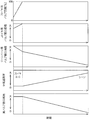
- the valve has a certain opening area that realizes the excess air ratio of stoichiometric operation, and when switching from stoichiometric operation to lean operation, the opening area is uniform over time until the switching operation ends.
- the excess air ratio decreases and the excess air ratio for lean operation is secured, and a certain opening area is secured.
- time elapses until the switching operation ends.
- the opening area is controlled so that the opening area increases uniformly and the excess air ratio decreases.
- the valve is configured such that a stoichiometric valve unit that realizes an excess air ratio in stoichiometric operation and a lean valve unit that realizes an excess air ratio in lean operation are connected in series with the stoichiometric valve unit. In this way, the opening area of the valve is controlled.
- the lean valve part In stoichiometric operation, the lean valve part is fully opened, the valve opening area is controlled by the stoichiometric valve part, and when switching from stoichiometric operation to lean operation, the stoichiometric valve part is fully opened and the lean valve part
- the opening area of the valve may be controlled while closing the valve.
- the stoichiometric valve In lean operation, the stoichiometric valve is fully opened and the valve opening area is controlled by the lean valve. When switching from lean to stoichiometric operation, the lean valve is fully opened and the stoichiometric valve is opened. The opening area of the valve may be controlled while closing the part.
- the opening area of the stoichiometric valve part and the opening area of the lean valve part are estimated and calculated to control the opening area. There may be.
- a gas heat pump device of the present invention for solving the above-described problems has the above gas engine.
- the cogeneration apparatus of the present invention for solving the above-described problems has the gas engine.
- a gas engine control method for solving the above-mentioned problems is a gas engine that performs stoichiometric operation when the engine is high load and lean operation when the engine is low and medium load, and is a mixture of air and fuel gas in the gas engine.
- a certain opening area that realizes the excess air ratio of the stoichiometric operation is secured, and when switching from the stoichiometric operation to the lean operation, the switching operation is completed.
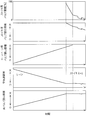
- the opening area is reduced uniformly to increase the excess air ratio, and during lean operation, a certain opening area is ensured to achieve the excess air ratio of the lean operation.
- the opening area is increased uniformly over time to reduce the excess air ratio. And it performs the opening area control so.
- stoichiometric operation can be performed when high load is required, and lean operation can be performed at medium and low load, so the range of load that can be handled is expanded, so various equipment devices such as gas heat pump devices and cogeneration devices When this gas engine is used, it is possible to use an optimal gas engine even with a small displacement, thereby reducing costs and saving energy.
- the gas heat pump device using such a gas engine can improve the energy consumption efficiency (APF) throughout the year, and the overall energy efficiency of the cogeneration device can also be improved.
- APF energy consumption efficiency
- FIG. 1 is a block diagram showing an outline of the overall configuration of the gas engine 1
- FIG. 2 shows a change in valve opening area when the gas engine 1 shifts from stoichiometric operation to lean operation
- FIG. A change in valve opening area when the engine 1 shifts from lean operation to stoichiometric operation is shown.
- This gas engine 1 is a gas engine 1 that performs stoichiometric operation at high loads and lean operation at medium and low loads
- the valve 2 is a valve section for stoichiometric that realizes an excess air ratio of stoichiometric operation from the mixer 24 to the regulator 23.
- 21 and a lean valve section 22 that realizes an excess air ratio in lean operation are connected in series with the stoichiometric valve section 21 on the mixer 24 side, and are provided between the regulator 23 and the mixer 24.
- the regulator 23 controls the pressure of the fuel gas so that the fuel gas can be always supplied at a constant pressure.
- the mixer 24 is configured by a Venturi tube that mixes fuel gas and air.
- the mixer 24 is configured to mix fuel gas and air by the venturi effect of the air sucked according to the opening degree of the throttle valve 25 provided on the downstream side.
- the valve 2 having the above configuration is connected to the intake port 11 of the cylinder head 10 of the gas engine 1.
- the gas engine 1 is provided with a sensor (not shown) for measuring the oxygen concentration in the exhaust gas in the exhaust passage and the like, and the excess air ratio is measured based on the measurement detection result. Yes.
- the gas engine 1 can smoothly switch between the stoichiometric operation and the lean operation by controlling the valve 2 and the like by the control unit 3 based on the measurement detection result by the sensor and the like. Further, in the stoichiometric operation, although concentration of NO X in the exhaust gas becomes high, is the reduction treatment by providing a three-way catalyst in an exhaust passage.
- stoichiometric operation is performed in an operating environment that requires high output.
- the stoichiometric valve unit 21 increases the opening area and the fuel gas concentration increases when the opening is increased, that is, the excess air ratio decreases, and the opening area decreases and the fuel gas concentration decreases when the opening is decreased. That is, the excess air ratio increases.
- the stoichiometric valve section 21 and the lean valve section 22 can be controlled based on the control accuracy of the stoichiometric valve section 21.
- the lean operation is not disturbed in synchronization with the increase in the opening area of the lean valve portion 22.
- the opening degree of the stoichiometric valve portion 21 that has been fully opened is gradually lowered from 100%.
- the control accuracy of the lean valve section 22 and the control accuracy of the stoichiometric valve section 21 are used.
- the lean valve portion is adjusted so that the increasing ratio of the opening area that increases due to the change in the opening degree of the lean valve portion 21 matches the decreasing ratio of the opening area that decreases as the opening amount of the stoichiometric valve portion 21 changes.
- the change in the opening degree of the stoichiometric valve unit 21 with respect to the change in the opening degree 22 is estimated and calculated.
- the transition time can be freely set by controlling the lean valve unit 22, so that the rotational fluctuation of the gas engine 1 is less than a predetermined threshold A so as not to damage the gas engine 1 and the like. It can be performed over a switching time.
- the valve response speed needs to be increased as compared with the lean control.
- the stoichiometric valve portion 21 is disposed closer to the mixer 24 than the lean valve portion 22. Since the stoichiometric valve portion 21 and the mixer 24 are close to each other and the staying gas can be reduced, the control delay can be reduced.
- the stoichiometric valve unit 21 controls the lean valve unit 22 that performs lean operation. By switching, the lean operation and the stoichiometric operation can be made compatible.
- the gas engine 1 thus configured can be suitably used as a drive source for a gas heat pump device (not shown).
- the gas heat pump device is required to have a high load in winter and summer, but can sufficiently cope with a medium and low load in the spring and autumn seasons.
- the gas engine 1 drives a plurality of compressors when a high load is required, and conversely, when the load is low, it is normal to drive a single compressor. Therefore, the gas heat pump device using the gas engine 1 can perform lean operation when the load is medium and low, and can switch to the stoichiometric operation when high load is required. The cost can be reduced by using the gas engine 1 having the displacement.
- the stoichiometric operation reduces the thermal efficiency, but the mechanical efficiency increases by driving multiple compressors, so the thermal efficiency is equivalent to the lean operation at medium and low loads.
- the thermal efficiency at the time of medium and low loads is excellent because the lean operation is performed. Therefore, it is possible to increase the efficiency of year-round energy consumption efficiency (APF).
- the gas engine 1 can also be suitably used as a drive source for a cogeneration device (not shown). That is, the cogeneration apparatus can achieve energy saving by performing a stoichiometric operation when performing a lean operation during normal operation and switching to a heat main operation with a high load.
- the gas engine according to the present invention is used as a drive source for various energy saving facilities.
Landscapes
- Engineering & Computer Science (AREA)
- Chemical & Material Sciences (AREA)
- Combustion & Propulsion (AREA)
- Mechanical Engineering (AREA)
- General Engineering & Computer Science (AREA)
- Chemical Kinetics & Catalysis (AREA)
- General Chemical & Material Sciences (AREA)
- Oil, Petroleum & Natural Gas (AREA)
- Electrical Control Of Air Or Fuel Supplied To Internal-Combustion Engine (AREA)
- Output Control And Ontrol Of Special Type Engine (AREA)
- Combined Controls Of Internal Combustion Engines (AREA)
- Control Of Vehicle Engines Or Engines For Specific Uses (AREA)
Abstract
Description
2 バルブ
21 ストイキ用バルブ部
22 リーン用バルブ部
23 レギュレータ
24 ミキサー
Claims (8)
- エンジンの高負荷時にはストイキ運転し、中低負荷時にはリーン運転するガスエンジンであって、
ガスエンジンに空気と燃料ガスとの混合気を供給するバルブは、
ストイキ運転の空気過剰率を実現する一定の開口面積が確保され、
ストイキ運転からリーン運転に切り替える際には、切り替え運転を終了するまでの間、時間の経過とともに一様に開口面積が減少して空気過剰率が上昇し、
リーン運転の空気過剰率を実現する一定の開口面積が確保され、
リーン運転からストイキ運転に切り替える際には、切り替え運転を終了するまでの間、時間の経過とともに開口面積が一様に増加して空気過剰率が減少する、
ように開口面積制御が行われることを特徴とするガスエンジン。 - バルブは、ストイキ運転の空気過剰率を実現するストイキ用バルブ部と、リーン運転の空気過剰率を実現するリーン用バルブ部とを直列でストイキ用バルブ部をエンジン吸気側につなげてバルブの開口面積の制御を行う請求項1記載のガスエンジン。
- ストイキ運転では、リーン用バルブ部を全開にし、ストイキ用バルブ部でバルブの開口面積の制御を行い、
ストイキ運転からリーン運転に切り替える際は、ストイキ用バルブ部を全開にするとともに、リーン用バルブ部を閉じながらバルブの開口面積の制御を行う請求項2記載のガスエンジン。 - リーン運転では、ストイキ用バルブ部を全開にし、リーン用バルブ部でバルブの開口面積の制御を行い、
リーン運転からストイキ運転に切り替える際には、リーン用バルブ部を全開にするとともに、ストイキ用バルブ部を閉じながらバルブの開口面積の制御を行う請求項2記載のガスエンジン。 - ストイキ運転からリーン運転に切り替える際またはリーン運転からストイキ運転に切り替える際に、ストイキ用バルブ部の開口面積とリーン用バルブ部の開口面積との合計を推定計算して開口面積の制御を行う請求項3または4記載のガスエンジン。
- 請求項1ないし5の何れか一記載のガスエンジンを有するガスヒートポンプ装置。
- 請求項1ないし5の何れか一記載のガスエンジンを有するコージェネレーション装置。
- エンジンの高負荷時にはストイキ運転し、中低負荷時にはリーン運転するガスエンジンにおいて、
ガスエンジンに空気と燃料ガスとの混合気を供給するバルブは、
ストイキ運転の際には、当該ストイキ運転の空気過剰率を実現する一定の開口面積を確保し、
ストイキ運転からリーン運転に切り替える際には、切り替え運転を終了するまでの間、時間の経過とともに一様に開口面積を減少させて空気過剰率を上昇させ、
リーン運転の際には、当該リーン運転の空気過剰率を実現する一定の開口面積を確保し、
リーン運転からストイキ運転に切り替える際には、切り替え運転を終了するまでの間、時間の経過とともに開口面積を一様に増加させて空気過剰率を減少させる、
ように開口面積制御を行うことを特徴とするガスエンジンの制御方法。
Priority Applications (4)
| Application Number | Priority Date | Filing Date | Title |
|---|---|---|---|
| AU2012330248A AU2012330248B2 (en) | 2011-10-25 | 2012-10-09 | Gas engine, gas heat pump device and cogeneration device that use gas engine, and method for controlling gas engine |
| US14/354,250 US9790886B2 (en) | 2011-10-25 | 2012-10-09 | Gas engine, gas heat pump system and cogeneration system using the gas engine, and method for controlling the gas engine |
| KR1020147011106A KR101883531B1 (ko) | 2011-10-25 | 2012-10-09 | 가스 엔진, 가스 엔진을 이용한 가스 히트 펌프 장치 및 코제너레이션 장치, 그리고 가스 엔진의 제어 방법 |
| CN201280050465.7A CN103890355B (zh) | 2011-10-25 | 2012-10-09 | 燃气发动机、利用该燃气发动机的燃气热泵装置和热电联产装置和燃气发动机的控制方法 |
Applications Claiming Priority (2)
| Application Number | Priority Date | Filing Date | Title |
|---|---|---|---|
| JP2011233851A JP5848947B2 (ja) | 2011-10-25 | 2011-10-25 | ガスエンジン、ガスエンジンを利用したヒートポンプ装置およびコージェネレーション装置 |
| JP2011-233851 | 2011-10-25 |
Publications (1)
| Publication Number | Publication Date |
|---|---|
| WO2013061768A1 true WO2013061768A1 (ja) | 2013-05-02 |
Family
ID=48167602
Family Applications (1)
| Application Number | Title | Priority Date | Filing Date |
|---|---|---|---|
| PCT/JP2012/076119 Ceased WO2013061768A1 (ja) | 2011-10-25 | 2012-10-09 | ガスエンジン、ガスエンジンを利用したガスヒートポンプ装置およびコージェネレーション装置、ならびにガスエンジンの制御方法 |
Country Status (6)
| Country | Link |
|---|---|
| US (1) | US9790886B2 (ja) |
| JP (1) | JP5848947B2 (ja) |
| KR (1) | KR101883531B1 (ja) |
| CN (1) | CN103890355B (ja) |
| AU (1) | AU2012330248B2 (ja) |
| WO (1) | WO2013061768A1 (ja) |
Families Citing this family (4)
| Publication number | Priority date | Publication date | Assignee | Title |
|---|---|---|---|---|
| JP6023616B2 (ja) * | 2013-03-19 | 2016-11-09 | ヤンマー株式会社 | ガスエンジン、ガスエンジンを利用したガスヒートポンプ装置およびコージェネレーション装置、ならびにガスエンジンの制御方法 |
| JP6270631B2 (ja) | 2014-05-30 | 2018-01-31 | ヤンマー株式会社 | ガスエンジン |
| JP7190941B2 (ja) * | 2019-03-05 | 2022-12-16 | 大阪瓦斯株式会社 | エンジン、その遠隔監視装置、及びそのメンテナンス周期調整方法 |
| CN114645793B (zh) * | 2022-05-23 | 2023-06-13 | 四川中能西控低碳动力装备有限公司 | 一种燃气发动机 |
Citations (5)
| Publication number | Priority date | Publication date | Assignee | Title |
|---|---|---|---|---|
| JPH0763075A (ja) * | 1993-08-25 | 1995-03-07 | Aisan Ind Co Ltd | 気体燃料機関の空燃比制御装置 |
| JPH0777076A (ja) * | 1993-09-06 | 1995-03-20 | Aisan Ind Co Ltd | 気体燃料機関の空燃比制御装置 |
| JP2003254106A (ja) * | 2002-02-28 | 2003-09-10 | Yamaha Motor Co Ltd | 圧縮着火式デュアルフューエルエンジンの燃料供給装置 |
| JP2006322403A (ja) * | 2005-05-19 | 2006-11-30 | Toyota Industries Corp | 内燃機関のガス燃料供給装置及び供給制御方法 |
| JP2011122484A (ja) * | 2009-12-09 | 2011-06-23 | Ygk:Kk | エンジンの燃料供給装置及びエンジン発電機 |
Family Cites Families (12)
| Publication number | Priority date | Publication date | Assignee | Title |
|---|---|---|---|---|
| JPS5154132A (en) * | 1974-11-08 | 1976-05-13 | Nissan Motor | Nainenkikanno nenryoseigyosochi |
| JPS5164137A (ja) * | 1974-11-29 | 1976-06-03 | Nissan Motor | |
| US4279230A (en) * | 1977-05-06 | 1981-07-21 | Societe Industrielle De Brevets Et D'etudes S.I.B.E. | Fuel control systems for internal combustion engines |
| JPS5660845A (en) * | 1979-10-20 | 1981-05-26 | Mazda Motor Corp | Air-fuel ratio control device for engine |
| JPS5724436A (en) * | 1980-07-21 | 1982-02-09 | Honda Motor Co Ltd | Deceleration control device of air-fuel ratio controller for internal combustion engine |
| US6189523B1 (en) * | 1998-04-29 | 2001-02-20 | Anr Pipeline Company | Method and system for controlling an air-to-fuel ratio in a non-stoichiometric power governed gaseous-fueled stationary internal combustion engine |
| JP2000024465A (ja) | 1998-07-10 | 2000-01-25 | Yanmar Diesel Engine Co Ltd | 内燃機関の制御方法 |
| JP3664919B2 (ja) * | 1999-08-16 | 2005-06-29 | 株式会社東芝 | ガスエンジンシステム |
| JP2007278198A (ja) * | 2006-04-07 | 2007-10-25 | Toyota Industries Corp | 予混合圧縮着火機関及び予混合圧縮着火機関の吸気制御方法 |
| JP4798091B2 (ja) * | 2007-07-19 | 2011-10-19 | トヨタ自動車株式会社 | 内燃機関の制御装置 |
| JP2009103112A (ja) * | 2007-10-25 | 2009-05-14 | Honda Motor Co Ltd | コージェネレーションシステム |
| JP5285309B2 (ja) * | 2008-03-14 | 2013-09-11 | ヤンマー株式会社 | 排気ガス浄化装置 |
-
2011
- 2011-10-25 JP JP2011233851A patent/JP5848947B2/ja not_active Expired - Fee Related
-
2012
- 2012-10-09 AU AU2012330248A patent/AU2012330248B2/en not_active Ceased
- 2012-10-09 KR KR1020147011106A patent/KR101883531B1/ko active Active
- 2012-10-09 CN CN201280050465.7A patent/CN103890355B/zh not_active Expired - Fee Related
- 2012-10-09 WO PCT/JP2012/076119 patent/WO2013061768A1/ja not_active Ceased
- 2012-10-09 US US14/354,250 patent/US9790886B2/en not_active Expired - Fee Related
Patent Citations (5)
| Publication number | Priority date | Publication date | Assignee | Title |
|---|---|---|---|---|
| JPH0763075A (ja) * | 1993-08-25 | 1995-03-07 | Aisan Ind Co Ltd | 気体燃料機関の空燃比制御装置 |
| JPH0777076A (ja) * | 1993-09-06 | 1995-03-20 | Aisan Ind Co Ltd | 気体燃料機関の空燃比制御装置 |
| JP2003254106A (ja) * | 2002-02-28 | 2003-09-10 | Yamaha Motor Co Ltd | 圧縮着火式デュアルフューエルエンジンの燃料供給装置 |
| JP2006322403A (ja) * | 2005-05-19 | 2006-11-30 | Toyota Industries Corp | 内燃機関のガス燃料供給装置及び供給制御方法 |
| JP2011122484A (ja) * | 2009-12-09 | 2011-06-23 | Ygk:Kk | エンジンの燃料供給装置及びエンジン発電機 |
Also Published As
| Publication number | Publication date |
|---|---|
| JP2013092082A (ja) | 2013-05-16 |
| AU2012330248A2 (en) | 2014-06-05 |
| CN103890355B (zh) | 2016-08-17 |
| KR20140071451A (ko) | 2014-06-11 |
| JP5848947B2 (ja) | 2016-01-27 |
| AU2012330248B2 (en) | 2016-08-25 |
| US9790886B2 (en) | 2017-10-17 |
| US20140311448A1 (en) | 2014-10-23 |
| KR101883531B1 (ko) | 2018-07-30 |
| AU2012330248A1 (en) | 2014-05-29 |
| CN103890355A (zh) | 2014-06-25 |
Similar Documents
| Publication | Publication Date | Title |
|---|---|---|
| JP5902629B2 (ja) | 自動車エンジンのegr回路の制御方法、この方法を実施するための弁、およびこの弁を備えるエンジン | |
| JP4877205B2 (ja) | 内燃機関の制御装置 | |
| CN115667695B (zh) | 用于管理多个排气再循环冷却器的系统和方法 | |
| WO2006077708A1 (ja) | Egr装置 | |
| CN101535620A (zh) | 均质充量压缩着火引擎 | |
| JP5848947B2 (ja) | ガスエンジン、ガスエンジンを利用したヒートポンプ装置およびコージェネレーション装置 | |
| JP4218702B2 (ja) | 内燃機関の排気還流装置 | |
| US7562527B2 (en) | Internal combustion engine with a supercharger | |
| JPWO2013094379A1 (ja) | 希薄燃料吸入ガスタービンの制御方法および制御装置 | |
| WO2020122107A1 (ja) | 内燃機関システム、車両および燃料供給方法 | |
| JP2009191668A (ja) | 過給装置及び過給エンジンシステム | |
| JP6023616B2 (ja) | ガスエンジン、ガスエンジンを利用したガスヒートポンプ装置およびコージェネレーション装置、ならびにガスエンジンの制御方法 | |
| JP3680537B2 (ja) | ディーゼルエンジン | |
| JP2019152122A (ja) | 内燃機関システム | |
| WO2013061769A1 (ja) | ガスエンジンならびにガスエンジンを利用したガスヒートポンプ装置およびコージェネレーション装置 | |
| JP2011220305A (ja) | 内燃機関の制御装置 | |
| JP2007303380A (ja) | 内燃機関の排気制御装置 | |
| JP2012167638A (ja) | 内燃機関の排気ガス再循環制御方法 | |
| JP2008150978A (ja) | 内燃機関の排気還流装置 | |
| NL2029326B1 (en) | A powertrain for a truck | |
| JP4996567B2 (ja) | エンジン | |
| JP2008208805A (ja) | 給気放出式空燃比制御装置をそなえたエンジン | |
| JP2007146854A5 (ja) | ||
| JP2010248969A (ja) | 内燃機関の制御装置 | |
| JP2012229622A (ja) | 内燃機関のegr制御装置 |
Legal Events
| Date | Code | Title | Description |
|---|---|---|---|
| 121 | Ep: the epo has been informed by wipo that ep was designated in this application |
Ref document number: 12843574 Country of ref document: EP Kind code of ref document: A1 |
|
| ENP | Entry into the national phase |
Ref document number: 20147011106 Country of ref document: KR Kind code of ref document: A |
|
| NENP | Non-entry into the national phase |
Ref country code: DE |
|
| WWE | Wipo information: entry into national phase |
Ref document number: 14354250 Country of ref document: US |
|
| ENP | Entry into the national phase |
Ref document number: 2012330248 Country of ref document: AU Date of ref document: 20121009 Kind code of ref document: A |
|
| 122 | Ep: pct application non-entry in european phase |
Ref document number: 12843574 Country of ref document: EP Kind code of ref document: A1 |