WO2013061512A1 - 摩擦伝動ベルト及びその製造方法 - Google Patents
摩擦伝動ベルト及びその製造方法 Download PDFInfo
- Publication number
- WO2013061512A1 WO2013061512A1 PCT/JP2012/006194 JP2012006194W WO2013061512A1 WO 2013061512 A1 WO2013061512 A1 WO 2013061512A1 JP 2012006194 W JP2012006194 W JP 2012006194W WO 2013061512 A1 WO2013061512 A1 WO 2013061512A1
- Authority
- WO
- WIPO (PCT)
- Prior art keywords
- belt
- powder
- layer
- cloth
- pulley
- Prior art date
- Legal status (The legal status is an assumption and is not a legal conclusion. Google has not performed a legal analysis and makes no representation as to the accuracy of the status listed.)
- Ceased
Links
Images







Classifications
-
- F—MECHANICAL ENGINEERING; LIGHTING; HEATING; WEAPONS; BLASTING
- F16—ENGINEERING ELEMENTS AND UNITS; GENERAL MEASURES FOR PRODUCING AND MAINTAINING EFFECTIVE FUNCTIONING OF MACHINES OR INSTALLATIONS; THERMAL INSULATION IN GENERAL
- F16G—BELTS, CABLES, OR ROPES, PREDOMINANTLY USED FOR DRIVING PURPOSES; CHAINS; FITTINGS PREDOMINANTLY USED THEREFOR
- F16G5/00—V-belts, i.e. belts of tapered cross-section
- F16G5/04—V-belts, i.e. belts of tapered cross-section made of rubber
- F16G5/06—V-belts, i.e. belts of tapered cross-section made of rubber with reinforcement bonded by the rubber
- F16G5/08—V-belts, i.e. belts of tapered cross-section made of rubber with reinforcement bonded by the rubber with textile reinforcement
-
- B—PERFORMING OPERATIONS; TRANSPORTING
- B29—WORKING OF PLASTICS; WORKING OF SUBSTANCES IN A PLASTIC STATE IN GENERAL
- B29D—PRODUCING PARTICULAR ARTICLES FROM PLASTICS OR FROM SUBSTANCES IN A PLASTIC STATE
- B29D29/00—Producing belts or bands
-
- B—PERFORMING OPERATIONS; TRANSPORTING
- B29—WORKING OF PLASTICS; WORKING OF SUBSTANCES IN A PLASTIC STATE IN GENERAL
- B29D—PRODUCING PARTICULAR ARTICLES FROM PLASTICS OR FROM SUBSTANCES IN A PLASTIC STATE
- B29D29/00—Producing belts or bands
- B29D29/10—Driving belts having wedge-shaped cross-section
- B29D29/103—Multi-ribbed driving belts
-
- F—MECHANICAL ENGINEERING; LIGHTING; HEATING; WEAPONS; BLASTING
- F16—ENGINEERING ELEMENTS AND UNITS; GENERAL MEASURES FOR PRODUCING AND MAINTAINING EFFECTIVE FUNCTIONING OF MACHINES OR INSTALLATIONS; THERMAL INSULATION IN GENERAL
- F16G—BELTS, CABLES, OR ROPES, PREDOMINANTLY USED FOR DRIVING PURPOSES; CHAINS; FITTINGS PREDOMINANTLY USED THEREFOR
- F16G1/00—Driving-belts
- F16G1/06—Driving-belts made of rubber
- F16G1/08—Driving-belts made of rubber with reinforcement bonded by the rubber
-
- F—MECHANICAL ENGINEERING; LIGHTING; HEATING; WEAPONS; BLASTING
- F16—ENGINEERING ELEMENTS AND UNITS; GENERAL MEASURES FOR PRODUCING AND MAINTAINING EFFECTIVE FUNCTIONING OF MACHINES OR INSTALLATIONS; THERMAL INSULATION IN GENERAL
- F16G—BELTS, CABLES, OR ROPES, PREDOMINANTLY USED FOR DRIVING PURPOSES; CHAINS; FITTINGS PREDOMINANTLY USED THEREFOR
- F16G5/00—V-belts, i.e. belts of tapered cross-section
- F16G5/20—V-belts, i.e. belts of tapered cross-section with a contact surface of special shape, e.g. toothed
Definitions
- the present invention relates to a friction transmission belt including a belt body formed of a rubber composition and a method for manufacturing the same.
- Patent Document 1 discloses that powder such as talc is adhered to the surface of the V-rib after vulcanization molding of the V-ribbed belt.
- Patent Document 2 discloses that a part of a short fiber protrudes from the V rib surface of a V-ribbed belt, and a powder such as talc is attached so that the protruding part of the short fiber is embedded. .
- Patent Document 3 discloses manufacturing a V-ribbed belt in which short fibers are firmly attached to the surface of the V-rib by applying an adhesive to the surface of the vulcanized belt sleeve and spraying the short fibers thereon. Has been.
- Patent Document 4 an adhesive is applied to an inner peripheral surface of an outer mold whose inner peripheral surface is engraved with a V-rib mold, and short fibers are sprayed thereon to adhere to the inner mold, while an uncrosslinked rubber composition is applied to the inner mold. It is disclosed that a V-ribbed belt having short fibers attached to the surface of the V-rib is manufactured by setting the core wire.
- Patent Document 5 proposes that a powder layer is combined and integrally provided on the pulley contact side surface of the rib of the V-ribbed belt so as to cover the pulley contact side surface.
- the present invention has been made in view of such a point, and an object of the present invention is to be able to obtain a suppression effect of slip noise generated between the pulley and the pulley over a long period of time as well as against water. There is to do.
- the first invention presupposes a friction transmission belt that includes a belt body formed of a rubber composition and is wound around a pulley to transmit power.
- a cloth layer is integrally provided on the pulley contact side surface of the belt main body so as to cover the pulley contact side surface, and this cloth layer exists in a state where powder is embedded in the fibers of the cloth layer. is doing.
- the second invention is premised on a friction transmission belt that includes a belt body formed of a rubber composition and is wound around a pulley to transmit power.
- a cloth layer is integrally provided on the pulley contact side surface of the belt body so as to cover the pulley contact side surface.
- the surface of the cloth layer is covered with powder, and the powder is fixed in a state where at least a part thereof is integrated with the rubber composition exuded from the belt body inside the fiber of the cloth layer.
- the third invention is premised on a friction transmission belt that includes a belt body formed of a rubber composition and is wound around a pulley to transmit power.
- a belt-forming uncrosslinked rubber composition in which a cloth is wound around a powder layer provided on a molding surface for forming a pulley contact side portion of a belt body in a belt mold is used. So that the uncrosslinked rubber composition is cross-linked while stretching the cloth, so that the powder is present in the fiber layer of the cloth layer covering the pulley contact side surface of the belt body. Is formed.
- the fabric layer is made of any one of a nonwoven fabric, a woven fabric, and a knitted fabric, and a part of the fabric layer is embedded in the belt body. It is.
- the powder is made of at least one of PTFE, montmorillonite, talc, calcium carbonate, silica, and layered silicate.
- the belt main body is laminated on a pulley contact side surface rubber layer in which a friction coefficient reducing material is blended, and on the inside thereof.
- An internal rubber layer, and a cloth layer is provided on the surface of the surface rubber layer.
- a friction for cross-linking the uncrosslinked rubber composition by press-contacting the uncrosslinked rubber composition for forming a belt with a molding surface for forming the pulley contact side portion of the belt body in the belt mold is a premise.
- a powder layer is formed by spraying powder onto the molding surface, and an uncrosslinked rubber composition for belt formation in which a cloth is wrapped around the surface of the powder layer is pressed with the cloth on the surface. And crosslinking the uncrosslinked rubber composition.
- the powder sprayed on the molding surface of the belt mold is charged.
- the cloth layer is integrally provided so as to cover the pulley contact side surface of the belt body in the friction transmission belt, and the powder is fixed and integrated in the cloth layer in a state where the powder is embedded in the fibers of the cloth layer. .
- the pulley contact surface is covered with the cloth layer so that the rubber is not directly exposed, and the generation of noise due to the exposure of the rubber can be prevented.
- the powder existing inside the fibers of the fabric layer is difficult to peel off not only by water but also by wear, and the effect of suppressing slip noise generated with the pulley is stable over a long period of time. And the toughness life of the noise can be extended.
- FIG. 1 is a perspective view of a V-ribbed belt according to an embodiment of the present invention.
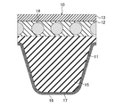
- FIG. 2 is an enlarged cross-sectional view of a main part of the V-ribbed belt.
- FIG. 3 is a view corresponding to FIG. 2 showing a modified example of the V-ribbed belt.
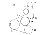
- FIG. 4 is a diagram showing a pulley layout of an auxiliary machine drive belt transmission of an automobile.
- FIG. 5 is a longitudinal sectional view of the belt mold.
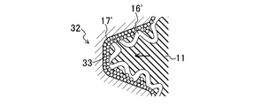
- FIG. 6 is an enlarged vertical sectional view of a part of the belt mold.
- FIG. 7 is an explanatory view showing a process of spraying powder onto the molding surface of the outer mold.
- FIG. 1 is a perspective view of a V-ribbed belt according to an embodiment of the present invention.
- FIG. 2 is an enlarged cross-sectional view of a main part of the V-ribbed belt.
- FIG. 3 is a view corresponding to FIG. 2 showing a modified example of the V-rib
- FIG. 8 is an explanatory view showing a process of setting an uncrosslinked rubber sheet, a twisted yarn and a cloth on the inner mold.
- FIG. 9 is an explanatory view showing a process of positioning the inner mold in the outer mold.
- FIG. 10 is an explanatory view showing a process of forming a belt slab.
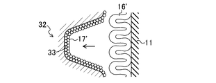
- FIG. 11 is a schematic cross-sectional view schematically showing a state before an uncrosslinked rubber sheet for forming a belt is pressed against an outer V-rib forming groove in the method for manufacturing a V-ribbed belt according to the embodiment of the present invention.
- FIG. 12 is a schematic cross-sectional view schematically showing a state in which an uncrosslinked rubber sheet for forming a belt is in pressure contact with an outer V-rib forming groove.
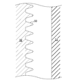
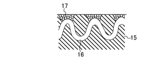
- FIG. 13 is a schematic cross-sectional view schematically showing the V-rib surface (side surface facing the belt width direction) of the molded V-ribbed belt.
- FIG. 14 is a view corresponding to FIG. 11 showing a case where a powder layer is formed on the surface of the cloth.
- FIG. 15 is a view corresponding to FIG. 12 showing a case where a powder layer is formed on the surface of the cloth.
- FIG. 16 is a view corresponding to FIG. 13 showing a case where a powder layer is formed on the surface of the cloth.
- V-ribbed belt B As a friction transmission belt according to an embodiment of the present invention, this V-ribbed belt B is used in, for example, an auxiliary machine drive belt transmission provided in an engine room of an automobile.
- the V-ribbed belt B has, for example, a belt circumferential length of 700 to 3000 mm, a belt width of 10 to 36 mm, and a belt thickness of 4.0 to 5.0 mm.
- the V-ribbed belt B includes a V-ribbed belt main body 10 configured in a triple layer of a compression rubber layer 11 on the inner peripheral side of the belt, an intermediate adhesive rubber layer 12 and a back rubber layer 13 (upper rubber layer) on the outer peripheral side of the belt. ing.
- a core wire 14 is embedded in the adhesive rubber layer 12 so as to form a spiral having a pitch in the belt width direction.
- a plurality of V ribs 15 are provided on the compressed rubber layer 11 so as to protrude toward the inner peripheral side of the belt.
- the plurality of V ribs 15 are each formed in a ridge having a substantially inverted triangular cross section extending in the belt length direction, and arranged in parallel in the belt width direction.
- Each V-rib 15 is formed to have a rib height of 2.0 to 3.0 mm and a width between base ends of 1.0 to 3.6 mm, for example.
- the number of ribs is, for example, 3 to 6 (in FIG. 1, the number of ribs is 6).
- the compressed rubber layer 11 is formed of a rubber composition obtained by heating and pressurizing an uncrosslinked rubber composition in which various compounding agents are blended and mixed with raw rubber to be crosslinked with a crosslinking agent.
- Examples of the raw rubber of the rubber composition forming the compressed rubber layer 11 include ethylene- ⁇ -olefin elastomer, chloroprene rubber (CR), chlorosulfonated polyethylene rubber (CSM), hydrogenated acrylonitrile rubber (H-NBR), and the like. It is done.
- the raw rubber may be composed of a single species, or may be composed of a blend of a plurality of species.
- the compounding agent examples include a reinforcing material such as carbon black, a vulcanization accelerator, a crosslinking agent, an antiaging agent, and a softening agent.
- carbon black for example, channel black; furnace black such as SAF, ISAF, N-339, HAF, N-351, MAF, FEF, SRF, GPF, ECF, N-234; FT, MT, etc. Thermal black; acetylene black is mentioned.
- Silica is also mentioned as a reinforcing agent.
- the reinforcing agent may be composed of a single species or a plurality of species.
- the reinforcing material preferably has a blending amount of 30 to 80 parts by mass with respect to 100 parts by mass of the raw rubber from the viewpoint of achieving a good balance between wear resistance and flex resistance.
- the vulcanization accelerator examples include metal oxides such as magnesium oxide and zinc oxide (zinc white), metal carbonates, fatty acids such as stearic acid, and derivatives thereof.
- the vulcanization accelerator may be composed of a single species or a plurality of species.
- the amount of the vulcanization accelerator is, for example, 0.5 to 8 parts by mass with respect to 100 parts by mass of the raw rubber.
- crosslinking agent examples include sulfur and organic peroxides.
- sulfur may be used, organic peroxide may be used, or both of them may be used in combination.
- the crosslinking agent is preferably used in an amount of 0.5 to 4.0 parts by mass with respect to 100 parts by mass of the raw rubber.
- the amount of the crosslinking agent is 100 parts by mass of the raw rubber. .5 to 8 parts by mass.
- Antiaging agents include amine-based, quinoline-based, hydroquinone derivatives, phenol-based and phosphite-based agents.
- the anti-aging agent may be composed of a single species or a plurality of species.
- the anti-aging agent is, for example, 0 to 8 parts by mass with respect to 100 parts by mass of the raw rubber.
- the softener examples include petroleum-based softeners, mineral oil-based softeners such as paraffin wax, castor oil, cottonseed oil, sesame oil, rapeseed oil, soybean oil, palm oil, palm oil, fallen raw oil, wax, rosin And vegetable oil-based softeners such as pine oil.
- the softener may be composed of a single species or a plurality of species.
- the amount of the softening agent other than the petroleum softening agent is 2 to 30 parts by mass with respect to 100 parts by mass of the raw rubber.
- layered silicates such as smectite group, vermulite group, kaolin group and the like may be included.
- the compressed rubber layer 11 may be composed of a single type of rubber composition, or may be composed of a plurality of types of rubber compositions laminated together.
- the compressed rubber layer 11 may have a pulley contact side surface layer 11 a in which a friction coefficient reducing material is blended and an internal rubber layer 11 b laminated on the inside thereof.
- the friction coefficient reducing material include short fibers such as nylon short fibers, vinylon short fibers, aramid short fibers, polyester short fibers, and cotton short fibers, and ultrahigh molecular weight polyethylene resins.
- the internal rubber layer 11b does not contain a short fiber or a friction coefficient reducing material.
- the cloth layer 16 is integrally formed on the surface of the V-ribbed belt body 10 so that the surface of the V-rib 15 which is the pulley contact side surface covers the surface of the V-rib 15 (pulley contact side surface). Is provided.
- the powder 17 is integrally present in the cloth layer 16 in a state where the powder 17 enters the fibers of the cloth layer 16 and is fixed by rubber.
- the surface of the cloth layer 16 is covered with the powder 17, and at least a part of the powder 17 oozes out from the V rib 15 in the V-ribbed belt body 10 inside the fiber of the cloth layer 16. It is fixed in an integrated state with the rubber composition (see FIG. 13).
- the powder 17 is present in the fibers of the fabric layer 16 while being submerged, for example, the following may be performed. That is, as shown in FIGS. 5 to 10, the powder 17 is applied to the molding surface of the inner peripheral surface of the outer mold 32 for forming the V rib 15 which is the pulley contact side portion of the V ribbed belt body 10 in the belt molding die 30.
- An uncrosslinked rubber composition for forming a belt (uncrosslinked rubber sheets 11 ′, 12 ′) in which a powder layer 17 ′ is provided by spraying and a cloth 16 ′ to be a cloth layer 16 is wound around the powder layer 17 ′ , 13 ') are pressed by a cloth 16' on the surface, and the uncrosslinked rubber composition is crosslinked while the cloth 16 'is stretched.
- the friction transmission belt B is formed so that the powder 17 is present in the fiber layer 16 fibers covering the surface of the V rib 15 (pulley contact side surface) of the V-ribbed belt body 10. It is a thing. This method will be described in detail later.
- the cloth 16 ′ constituting the cloth layer 16 is made of any one of a nonwoven fabric, a woven fabric, and a knitted fabric. Examples of the material for the cloth include nylon and polyester.
- the thickness of the fabric layer 16 is preferably about 0.1 to 2.0 mm, specifically 0.5 to 1.0 mm.
- the compressed rubber layer 11 is integrally provided with the cloth layer 16 so as to cover the surface of the V-rib 15 that is the pulley contact side surface, and the powder 17 is placed on the cloth layer 16 inside the fibers of the cloth layer 16. It is provided as a single unit in a submerged state. That is, when vulcanized molding of a V-ribbed belt is performed and powder such as talc is sprayed on the surface of the V-rib as in the prior art, the powder adhering to the surface of the V-rib contacts the pulley during belt running. There is a problem that it drops out in a short time.
- the V-ribbed belt main body is provided so that the powder layer is coated on the surface of the V-rib which is the pulley contact side surface of the compressed rubber layer, and the powder of the powder layer is compressed by the high temperature and high pressure during vulcanization molding. Even if the rubber composition is combined and integrated, abnormal noise is likely to occur due to the exposed portion of the combined rubber. Also, the powder is easily peeled off due to contact abrasion with the pulley, and the toughness life of abnormal noise is shortened.
- the cloth layer 16 is integrally provided so as to cover the surface of the V-ribbed belt body 10 on the surface of the V-rib 15 which is the pulley contact side surface of the compressed rubber layer 11. Then, the powder 17 sinks into the fibers of the fabric layer 16 and is integrally fixed. More specifically, the surface of the cloth layer 16 is covered with the powder 17, and at least a part of the powder 17 is a rubber that oozes out from the V rib 15 in the V-ribbed belt body 10 inside the fiber of the cloth layer 16. It is fixed in an integrated state with the composition.
- the powder 17 is exposed on the surface of the V-rib 15, there is no exposed portion of rubber (rubber composition), and no abnormal noise is generated by the rubber during belt running. Moreover, since the powder 17 is in a state of being submerged inside the fibers of the cloth layer 16, it is protected by the cloth layer 17 and is difficult to peel off. Even if the surface wears due to contact wear with the pulley, the powder 17 in the fibers of the fabric layer 16 is newly exposed from one to the next. Therefore, even when the belt B is used for a long period of time, the surface state hardly changes over the period, and the effect of suppressing the slip noise generated between the belt B and the pulley can be stably obtained over a long period of time. Can extend the toughness life of abnormal noise.
- the cloth layer 16 in which the powder 17 is immersed in the fiber may be provided so as to cover the entire surface of the V-rib 15 that is the pulley contact side surface.
- the surface of the V-rib 15 that is the pulley contact surface is partially covered such that only the surface of the V-rib 15 corresponding to the belt half circumference or only the surface of the inner or outer V-rib 15 in the belt width direction. May be provided.
- a part of the cloth layer 16 may be embedded in the compressed rubber layer 11 of the V-ribbed belt main body 10.
- Examples of the powder stored in the cloth layer 16 include PTFE, montmorillonite, talc, calcium carbonate, silica, layered silicate, and the like.
- the powder may be composed of a single species or a mixture of a plurality of species.
- the particle size of the powder is preferably from 0.1 to 150 ⁇ m, more preferably from 0.5 to 60 ⁇ m.
- the particle size is expressed by the sieve opening of the test sieve measured by the sieving method, expressed by the Stokes equivalent diameter by the sedimentation method, the equivalent sphere diameter by the light scattering method, and the electrical resistance test method.
- Examples of layered silicates include smectites, vermulites, and kaolins.
- Examples of the smectite group include montmorillonite, beidellite, saponite, and hectorite.
- Examples of the vermulite family include 3 octahedral vermulites, 2 octahedral vermulites, and the like.
- Examples of the kaolin family include kaolinite, dickite, halloysite, lizardite, amesite, and chrysotile.
- the layered silicate is preferably a smectite montmorillonite.
- the adhesive rubber layer 12 is formed in a band shape having a horizontally long cross section and has a thickness of, for example, 1.0 to 2.5 mm.
- the back rubber layer 13 is also formed in a band shape having a horizontally long cross section, and has a thickness of, for example, 0.4 to 0.8 mm.
- the surface of the back rubber layer 13 is preferably formed in a form in which the texture of the woven fabric is transferred from the viewpoint of suppressing the sound generated between the back rubber layer 13 and the flat pulley in contact with the belt back surface.
- the adhesive rubber layer 12 and the back rubber layer 13 are formed of a rubber composition obtained by cross-linking an uncrosslinked rubber composition obtained by blending various compounding ingredients in a raw rubber with a crosslinking agent by heating and pressing. Yes.
- the back rubber layer 13 is preferably formed of a rubber composition that is slightly harder than the adhesive rubber layer 12 from the viewpoint of suppressing the occurrence of adhesion due to contact with the flat pulley with which the belt back contacts.
- the compressed rubber layer 11 and the adhesive rubber layer 12 constitute a V-ribbed belt main body 10, and a woven fabric formed of, for example, cotton, polyamide fiber, polyester fiber, aramid fiber or the like instead of the back rubber layer 13 Further, a configuration in which a reinforcing fabric composed of a knitted fabric, a nonwoven fabric or the like is provided may be used.
- Examples of the raw rubber of the rubber composition for forming the adhesive rubber layer 12 and the back rubber layer 13 include, for example, ethylene- ⁇ -olefin elastomer, chloroprene rubber (CR), chlorosulfonated polyethylene rubber (CSM), hydrogenated acrylonitrile rubber ( H-NBR) and the like.
- the raw rubber for the adhesive rubber layer 12 and the back rubber layer 13 is preferably the same as the raw rubber for the compressed rubber layer 11.
- the compounding agent examples include a reinforcing material such as carbon black, a vulcanization accelerator, a crosslinking agent, an antiaging agent, a softening agent and the like, as in the case of the compressed rubber layer 11.
- the compressed rubber layer 11, the adhesive rubber layer 12, and the back rubber layer 13 may be formed of a rubber composition having a different composition, or may be formed of a rubber composition having the same composition.
- the core wire 14 is composed of twisted yarns such as polyester fiber (PET), polyethylene naphthalate fiber (PEN), aramid fiber, vinylon fiber and the like.
- PET polyester fiber
- PEN polyethylene naphthalate fiber
- aramid fiber vinylon fiber and the like.
- the core wire 14 is subjected to an adhesive treatment that is heated after being immersed in an RFL aqueous solution before molding and / or an adhesive treatment that is dried after being immersed in rubber paste in order to impart adhesion to the V-ribbed belt main body 10. .
- FIG. 4 shows a pulley layout of an auxiliary drive belt transmission device 20 for an automobile using the V-ribbed belt B according to the present embodiment.
- This accessory drive belt transmission device 20 is of a serpentine drive type in which a V-ribbed belt B is wound around six pulleys of four rib pulleys 21, 22, 25, 26 and two flat pulleys 23, 24 to transmit power. It is.
- the auxiliary drive belt transmission device 20 includes a power steering pulley 21 at the uppermost position, an AC generator pulley 22 disposed below the power steering pulley 21, and a flat pulley tensioner pulley disposed below the power steering pulley 21. 23, a flat water pump pulley 24 disposed below the tensioner pulley 23, a crankshaft pulley 25 disposed on the lower left side of the tensioner pulley 23, and a lower right side of the crankshaft pulley 25. And an air conditioner pulley 26. Among these, all except the tensioner pulley 23 and the water pump pulley 24 which are flat pulleys are rib pulleys.
- These rib pulleys 21, 22, 25, 26 and flat pulleys 23, 24 are made of, for example, a metal stamped product, a resin molded product such as a casting, nylon resin, or phenol resin.
- the pulley diameter is 50 to 150 mm.
- the belt span length which is the length of the V-ribbed belt B spanned between the pulleys 21 to 26, is, for example, 50 to 300 mm. Misalignment that can occur between the pulleys 21 to 26 is 0 to 2 °.
- the cloth layer 16 is integrally provided so as to cover the surface of the V rib 15 which is the pulley contact side surface of the compressed rubber layer 11 in the V ribbed belt main body 10 of the V ribbed belt B.
- the powder 17 is fixed and integrated in a state where the powder 17 is embedded. Therefore, also in this auxiliary machine drive belt transmission device 20, it is possible to obtain the effect of suppressing slip noise generated with the rib pulley such as the power steering pulley 21 over a long period of time.
- a cylindrical inner mold 31 (sleeve made of rubber or the like) and an outer mold 32 are provided concentrically with each other.
- a belt mold 30 is used.
- the inner mold 31 is made of a flexible material such as rubber.
- the outer peripheral surface of the inner mold 31 is configured as a molding surface for molding the outer peripheral surface of the belt B.
- the outer peripheral surface of the inner mold 31 is provided with a woven fabric texture forming pattern or the like.
- the outer mold 32 is formed of a rigid material such as metal.
- the inner peripheral surface of the outer mold 32 is configured as a molding surface for molding the inner peripheral surface of the belt B.
- V rib forming grooves 33 that form the V ribs 15 of the belt B are provided on the inner peripheral surface of the outer mold 32 at a constant pitch in the axial direction.
- the outer mold 32 is provided with a temperature control mechanism (not shown) for controlling the temperature by circulating a heat medium such as water vapor or a coolant such as water.
- the belt forming die 30 is provided with pressurizing means (not shown) using high-pressure air or the like for pressurizing and expanding the inner die 31 from the inside to the outside in the radial direction.
- each compound is blended with the raw rubber and kneaded with a kneader such as a kneader or a Banbury mixer.
- a kneader such as a kneader or a Banbury mixer.
- the uncrosslinked rubber composition obtained by this kneading is formed into a sheet shape by calendering or the like to produce an uncrosslinked rubber sheet 11 ′ (uncrosslinked rubber composition for forming a belt) for the compression rubber layer 11.
- uncrosslinked rubber sheets 12 'and 13' for the adhesive rubber layer 12 and the back rubber layer 13 are also produced.
- the adhesion process which immerses the twisted thread 14' in rubber paste and heat-drys is performed.
- powder layer 17 ′ is provided by spraying powder 17 on the molding surface for forming the pulley contact side portion of the inner peripheral surface of outer mold 32.
- the thickness of the powder layer 17 ′ is preferably 0.1 to 200 ⁇ m, and more preferably 1.0 to 100 ⁇ m.
- the powder 17 can be sprayed using a general powder coating apparatus.
- the uncrosslinked rubber sheet 13 'for the back rubber layer 13 and the uncrosslinked rubber sheet 12' for the adhesive rubber layer 12 are wound around the molding surface of the outer periphery of the inner mold 31 in order. Laminate.
- the twisted yarn 14 ′ for the core wire 14 is spirally wound around the cylindrical inner mold 31.
- an uncrosslinked rubber sheet 12 ′ for the adhesive rubber layer 12 and an uncrosslinked rubber sheet 11 ′ for the compression rubber layer 11 are sequentially wound and laminated thereon.
- a cloth 16 ′ to be a cloth layer 16 is wound around the uncrosslinked rubber sheet 11 ′ for the compressed rubber layer 11 and laminated.
- the uncrosslinked rubber sheet 11 ′ for the compressed rubber layer 11 is different for the pulley contact side surface layer 11a and the internal rubber layer 11b.
- a rubber composition may be used.
- the inner mold 31 is positioned in the outer mold 32 and sealed. At this time, the inside of the inner mold 31 is in a sealed state.
- the outer die 32 is heated and pressurized by injecting high-pressure air or the like into the sealed interior of the inner die 31 by a pressurizing means.
- the inner mold 31 expands radially and expands radially outward.
- the uncrosslinked rubber sheets 11, 12, 13 for forming the belt are pressed against the molding surface of the outer mold 32 by the cloth 16 'on the outer peripheral surface thereof, and the V rib is formed on the molding surface of the outer mold 32
- a plurality of V ribs 15 are formed by the grooves 33.
- the uncrosslinked rubber sheets 11, 12, and 13 are cross-linked and integrated with the cloth 16 'and combined with the twisted yarn 14'.
- a cylindrical belt slab in which the cloth layer 16 is integrated on the outer peripheral surface is formed.
- the powder 17 of the powder layer 17 ′ is fixed by a crosslinked rubber in a state of being submerged in the fibers of the fabric layer 16.
- the molding temperature of this belt slab is, for example, 100 to 180 ° C.
- the molding pressure is, for example, 0.5 to 2.0 MPa
- the molding time is, for example, 10 to 60 minutes.
- the powder 17 is not sprayed on the molding surface of the outer mold 32 in advance to provide the powder layer 17 ′.
- the following method may be considered.
- the cloth 16 ′ is wound and laminated on the uncrosslinked rubber sheet 11 ′ for the compressed rubber layer 11, and the powder layer 17 ′ is formed by spraying or coating the powder 17 on the surface of the cloth 16 ′.
- a method for forming the belt-forming uncrosslinked rubber sheets 11, 12, 13 by pressing against the molding surface of the outer mold 32 without the powder layer Powder layer 17 ′ is formed by spraying or coating powder 17 on the surface, and cloth 16 ′ on which powder layer 17 ′ is formed is used as uncrosslinked rubber sheet 11 for compressed rubber layer 11.
- the uncrosslinked rubber sheets 11, 12, 13 for forming the belt are pressed against the molding surface of the outer mold 32 without the powder layer and molded in the same manner as described above. .
- a powder layer 17 ′ is formed on the surface of the cloth 16 ′, and the cloth 16 ′ on the uncrosslinked rubber sheet 11 ′ is formed along with the molding. Greatly extends along the V-rib forming groove 33 on the molding surface of the outer mold 32. As the cloth 16 'extends on the uncrosslinked rubber sheet 11', as shown in FIG. 15, the powder layer 17 'formed on the surface of the cloth 16' accordingly follows the cloth 16 '. It will be greatly stretched and deformed. Therefore, even if the powder 17 is adhered to the surface of the cloth 16 ′ without any gap, a gap is generated in the powder layer 17 ′ due to the deformation of the surface of the cloth 16 ′.
- gum (rubber composition) of the uncrosslinked rubber sheet 11 oozes out from the back surface side of the cloth 16 'in the gap, and is wet and exposed on the front surface side.
- a part or most of the surface of the V-rib 15 which is the pulley contact side surface of the V-ribbed belt main body 10 becomes a rubber surface.
- the powder 17 does not sink into the fibers of the fabric layer 16 and adheres only to a part of the surface of the V rib 15, and the surface of the V rib 15 can be covered with the exposed powder 17. Disappear.
- the powder layer 17 ′ is not formed on the surface of the cloth 16 ′ as described above, and the powder 17 is brought into pulley contact with the inner peripheral surface of the outer mold 32 as shown in FIG. A powder layer 17 'is provided by spraying on the molding surface for forming the side portion. Therefore, as shown in FIG. 12, only the cloth 16 ′ wound around the uncrosslinked rubber sheet 11 ′ on the outer peripheral surface of the inner mold 31 extends along the V rib forming groove 33 on the molding surface of the outer mold 32 as described above. It is greatly stretched, and in its stretched state, it is pressed against the powder layer 17 'on the molding surface.
- the powder 17 on the molding surface of the outer mold 32 can smoothly enter into the fibers of the stretched cloth 16 ', and the powder layer 17' is placed on the cloth 16 'as described above. It does not move or deform following the elongation of the film.
- the manufactured V-ribbed belt B has most or all of the surface of the V-rib 15 that is the pulley contact side surface of the V-ribbed belt main body 10 (the side surface of the V-rib 15 facing the belt width direction). Will be covered with the exposed powder 17.
- the cloth 16 ' is stretched and deformed, the cloth is opened, and the cloth 16' is in contact with the powder layer 17 'with the open cloth. For this reason, the powder 17 enters the fibers of the fabric layer 16 more smoothly, and it is difficult for the powder to fall off due to friction with the pulley.
- the rubber (rubber composition) of the uncrosslinked rubber sheet 11 that has entered the fabric layer 16 from the back side tends to ooze out to the surface side of the fabric layer 16. However, it is blocked by the powder 17 that has entered the fiber layer 16 from the surface side into the fiber, and no rubber is exposed on the surface of the V-rib 15.
- the rubber and the powder 17 that are to ooze out on the surface are integrated and the powder 17 is fixed, and the powder 17 is difficult to peel off.
- the friction coefficient on the surface of the V-rib 15 can be kept low for a long period of time, and the effect of suppressing the slip noise generated with the pulley can be obtained for a long period of time.
- the size of the powder 17 and the size of the fibers of the cloth layer 16 and the cloth 16 ′ are shown for the sake of explanation.
- the powder 17 is present in the fibers of the cloth layer 16 (the surface of the cloth layer 16 is covered with the powder 17, and at least a part of the powder 17 is inside the fibers of the cloth layer 16.
- the V-ribbed belt main body 10 is fixed in a state of being integrated with the rubber composition exuded from the V-rib 15), as described above, and an uncrosslinked rubber composition for forming a belt having a cloth 16 ′ wound around the surface. It is reliable and effective only by a manufacturing method in which an article is brought into pressure contact with the powder layer 17 'on the molding surface of the inner peripheral surface of the outer mold 32 and the cloth 16' is stretched along the V-rib forming groove 33 on the molding surface. Can be realized.
- the V-ribbed belt B is shown as the friction transmission belt.
- the present invention is not particularly limited to this, and other friction transmission belts such as a low-edge type V belt may be used. is there.
- auxiliary drive belt transmission device 20 of the automobile was shown as an example of use of the friction transmission belt, it is not particularly limited to this, and it may be a belt transmission device for general industries or the like. Good.
- the present invention is extremely useful for a friction transmission belt in which a belt body formed of a rubber composition is wound around a pulley and transmits power, and a method for manufacturing the same, and has high industrial applicability.
- V-ribbed belt (friction drive belt) DESCRIPTION OF SYMBOLS 10 V ribbed belt body 11 Compression rubber layer 11 'Uncrosslinked rubber sheet 11a Pulley contact side surface layer 11b Internal rubber layer 12 Adhesive rubber layer 12' Uncrosslinked rubber sheet 13 Back rubber layer 13 'Uncrosslinked rubber sheet 14 Core wire 14' Twisted thread 15 V-rib (pulley contact side) 16 Cloth layer 16 'Cloth 17 Powder 17' Powder layer 20 Auxiliary drive belt transmission device 30 Belt mold 31 Inner mold 32 Outer mold 33 V-rib forming groove
Landscapes
- Engineering & Computer Science (AREA)
- General Engineering & Computer Science (AREA)
- Mechanical Engineering (AREA)
- Textile Engineering (AREA)
- Heating, Cooling, Or Curing Plastics Or The Like In General (AREA)
Abstract
Description
図1及び図2は、本発明の実施形態に係る摩擦伝動ベルトとしてのVリブドベルトBを示す。このVリブドベルトBは、後述するように、例えば自動車のエンジンルーム内に設けられる補機駆動ベルト伝動装置等に用いられる。VリブドベルトBは、例えばベルト周長700~3000mm、ベルト幅10~36mm、及びベルト厚さ4.0~5.0mmのものである。
図4は、本実施形態に係る上記VリブドベルトBを用いた自動車の補機駆動ベルト伝動装置20のプーリレイアウトを示す。この補機駆動ベルト伝動装置20は、VリブドベルトBが4つのリブプーリ21,22,25,26及び2つの平プーリ23,24の6つのプーリに巻き掛けられて動力を伝達するサーペンタインドライブ方式のものである。
次に、上記VリブドベルトBの製造方法の一例について図5~図10に基づいて説明する。
尚、本実施形態では、摩擦伝動ベルトとしてVリブドベルトBを示したが、特にこれに限定されるものではなく、ローエッジタイプのVベルト等、他の摩擦伝動ベルトであってもよいのは勿論である。
10 Vリブドベルト本体
11 圧縮ゴム層
11′ 未架橋ゴムシート
11a プーリ接触側表面層
11b 内部ゴム層
12 接着ゴム層
12′ 未架橋ゴムシート
13 背面ゴム層
13′ 未架橋ゴムシート
14 心線
14′ 撚り糸
15 Vリブ(プーリ接触側部分)
16 布層
16′ 布
17 粉体
17′ 粉体層
20 補機駆動ベルト伝動装置
30 ベルト成形型
31 内型
32 外型
33 Vリブ形成溝
Claims (8)
- ゴム組成物により形成されたベルト本体を備え、プーリに巻き掛けられて動力を伝達する摩擦伝動ベルトであって、
上記ベルト本体のプーリ接触側表面に布層が該プーリ接触側表面を被覆するように一体に設けられ、
上記布層には粉体が布層の繊維内部に潜り込んだ状態で存在している摩擦伝動ベルト。 - ゴム組成物により形成されたベルト本体を備え、プーリに巻き掛けられて動力を伝達する摩擦伝動ベルトであって、
上記ベルト本体のプーリ接触側表面に布層が該プーリ接触側表面を被覆するように一体に設けられ、
上記布層の表面は粉体により被覆され、かつ該粉体はその少なくとも一部が布層の繊維内部でベルト本体から染み出したゴム組成物と一体化した状態で固着されている摩擦伝動ベルト。 - ゴム組成物により形成されたベルト本体を備え、プーリに巻き掛けられて動力を伝達する摩擦伝動ベルトであって、
ベルト成形型においてベルト本体のプーリ接触側部分を形成するための成形面に設けられた粉体層に、表面に布を巻き付けたベルト形成用の未架橋ゴム組成物を表面の布で圧接させて、該布を伸ばしながら該未架橋ゴム組成物を架橋させることにより、ベルト本体のプーリ接触側表面を被覆した布層の繊維の内部に粉体が潜り込んだ状態で存在するように形成された摩擦伝動ベルト。 - 請求項1~3のいずれか1つにおいて、
布層が不織布、織物又は編み物のいずれかからなり、
布層の一部がベルト本体に埋め込まれている摩擦伝動ベルト。 - 請求項1~4のいずれか1つにおいて、
粉体はPTFE、モンモリロナイト、タルク、炭酸カルシウム、シリカ、層状珪酸塩のいずれか1種類以上からなる摩擦伝動ベルト。 - 請求項1~5のいずれか1つにおいて、
ベルト本体は、摩擦係数低減材が配合されたプーリ接触側表面ゴム層と、その内側に積層された内部ゴム層とを有し、
上記表面ゴム層の表面に布層が設けられている摩擦伝動ベルト。 - ベルト成形型においてベルト本体のプーリ接触側部分を形成するための成形面にベルト形成用の未架橋ゴム組成物を圧接させて、該未架橋ゴム組成物を架橋させる摩擦伝動ベルトの製造方法であって、
上記成形面に粉体を吹き付けて粉体層を形成する工程と、
上記粉体層に、表面に布を巻き付けたベルト形成用の未架橋ゴム組成物を表面の布で圧接させて、該未架橋ゴム組成物を架橋させる工程とを含む摩擦伝動ベルトの製造方法。 - 請求項7において、
ベルト成形型の成形面に吹き付ける粉体を帯電させる摩擦伝動ベルトの製造方法。
Priority Applications (5)
| Application Number | Priority Date | Filing Date | Title |
|---|---|---|---|
| DE112012004524.6T DE112012004524T5 (de) | 2011-10-28 | 2012-09-27 | Reibungsangetriebener Riemen und Herstellungsverfahren dafür |
| US14/350,705 US9822842B2 (en) | 2011-10-28 | 2012-09-27 | Friction drive belt and manufacturing method therefor |
| CN201280052841.6A CN103906945B (zh) | 2011-10-28 | 2012-09-27 | 摩擦传动带及其制造方法 |
| KR1020147013408A KR101950541B1 (ko) | 2011-10-28 | 2012-09-27 | 마찰 전동 벨트 및 그 제조방법 |
| JP2013540624A JP6158708B2 (ja) | 2011-10-28 | 2012-09-27 | 摩擦伝動ベルトの製造方法 |
Applications Claiming Priority (2)
| Application Number | Priority Date | Filing Date | Title |
|---|---|---|---|
| JP2011236917 | 2011-10-28 | ||
| JP2011-236917 | 2011-10-28 |
Publications (1)
| Publication Number | Publication Date |
|---|---|
| WO2013061512A1 true WO2013061512A1 (ja) | 2013-05-02 |
Family
ID=48167369
Family Applications (1)
| Application Number | Title | Priority Date | Filing Date |
|---|---|---|---|
| PCT/JP2012/006194 Ceased WO2013061512A1 (ja) | 2011-10-28 | 2012-09-27 | 摩擦伝動ベルト及びその製造方法 |
Country Status (6)
| Country | Link |
|---|---|
| US (1) | US9822842B2 (ja) |
| JP (2) | JP6158708B2 (ja) |
| KR (1) | KR101950541B1 (ja) |
| CN (1) | CN103906945B (ja) |
| DE (1) | DE112012004524T5 (ja) |
| WO (1) | WO2013061512A1 (ja) |
Cited By (4)
| Publication number | Priority date | Publication date | Assignee | Title |
|---|---|---|---|---|
| WO2015174005A1 (ja) * | 2014-05-14 | 2015-11-19 | バンドー化学株式会社 | 伝動ベルト |
| WO2015177953A1 (ja) * | 2014-05-22 | 2015-11-26 | バンドー化学株式会社 | 伝動ベルト |
| US10138981B2 (en) | 2014-09-26 | 2018-11-27 | Mitsuboshi Belting Ltd. | Power-transmitting friction belt and method for manufacturing same |
| CN110081135A (zh) * | 2019-04-28 | 2019-08-02 | 四川玉竹麻业有限公司 | 一种针梳机齿形带传动结构 |
Families Citing this family (10)
| Publication number | Priority date | Publication date | Assignee | Title |
|---|---|---|---|---|
| DE102013104757A1 (de) * | 2013-05-08 | 2014-11-13 | Contitech Antriebssysteme Gmbh | Verfahren zur Fertigung eines Riemens mit präparierten Zugträgern mit Hüllschicht |
| DE112015000769T5 (de) * | 2014-02-12 | 2016-11-10 | Bando Chemical Industries, Ltd. | Verfahren zum Herstellen eines Übertragungsriemens und Übertragungsriemen |
| JP6719385B2 (ja) * | 2014-04-08 | 2020-07-08 | ダイコ・ヨーロッパ・エッセ・エッレ・エッレ | 伝動ベルトおよび関連する伝動システム |
| JP6487037B2 (ja) * | 2015-04-24 | 2019-03-20 | バンドー化学株式会社 | 伝動ベルト |
| CN108778665A (zh) * | 2016-03-07 | 2018-11-09 | 沃尔特·弗兰德有限公司 | 用于生产驱动皮带的方法和驱动皮带 |
| US20170299017A1 (en) * | 2016-04-19 | 2017-10-19 | Contitech Antriebssysteme Gmbh | Cross linked elastomeric facing on cast polyurethane synchronous drive belts |
| DE102016209633A1 (de) * | 2016-06-02 | 2017-12-07 | Contitech Antriebssysteme Gmbh | Keilriemen und Verfahren zu seiner Herstellung |
| JP6690047B1 (ja) * | 2018-12-06 | 2020-04-28 | 三ツ星ベルト株式会社 | 摩擦伝動ベルト及びその製造方法 |
| CN111674066A (zh) * | 2020-06-18 | 2020-09-18 | 浙江威格尔传动股份有限公司 | 耐磨皮带的生产工艺 |
| JP7323560B2 (ja) * | 2021-01-29 | 2023-08-08 | バンドー化学株式会社 | 摩擦伝動ベルト |
Citations (4)
| Publication number | Priority date | Publication date | Assignee | Title |
|---|---|---|---|---|
| JP2003012818A (ja) * | 2001-06-28 | 2003-01-15 | Bando Chem Ind Ltd | ベルト用帆布及びそれを用いた伝動ベルト並びに高負荷伝動用vベルト |
| JP2010053935A (ja) * | 2008-08-27 | 2010-03-11 | Bando Chem Ind Ltd | Vリブドベルト |
| JP2010539394A (ja) * | 2007-09-14 | 2010-12-16 | ゲイツ・ユニッタ・アジア株式会社 | Vリブドベルトおよびその製造方法 |
| JP2011099457A (ja) * | 2008-03-07 | 2011-05-19 | Bando Chemical Industries Ltd | Vリブドベルト |
Family Cites Families (11)
| Publication number | Priority date | Publication date | Assignee | Title |
|---|---|---|---|---|
| JPH0731006Y2 (ja) | 1990-05-02 | 1995-07-19 | 三ツ星ベルト株式会社 | 動力伝動用ベルト |
| JPH0471131A (ja) | 1990-07-10 | 1992-03-05 | Toshiba Corp | パッファ形ガス遮断器 |
| JPH0731006U (ja) | 1993-11-16 | 1995-06-13 | 利昭 井原 | 医療用補助器具 |
| JP4409664B2 (ja) | 1999-05-14 | 2010-02-03 | 三ツ星ベルト株式会社 | ゴムベルト |
| JP4485147B2 (ja) | 2002-07-30 | 2010-06-16 | 三ツ星ベルト株式会社 | Vリブドベルトの製造方法 |
| JP2004162894A (ja) * | 2002-09-20 | 2004-06-10 | Noriatsu Kojima | 耐火二層管 |
| JP2004116755A (ja) | 2002-09-30 | 2004-04-15 | Mitsuboshi Belting Ltd | Vリブドベルトのリブ面への粉体付着方法及びその粉体付着装置 |
| JP2004276581A (ja) | 2003-01-17 | 2004-10-07 | Mitsuboshi Belting Ltd | 伝動ベルトの製造方法 |
| JP4071131B2 (ja) | 2003-02-25 | 2008-04-02 | 三ツ星ベルト株式会社 | 伝動ベルトの製造方法 |
| JP2005069358A (ja) * | 2003-08-25 | 2005-03-17 | Bando Chem Ind Ltd | 摩擦伝動ベルト及びその製造方法 |
| JP5508648B2 (ja) * | 2009-05-20 | 2014-06-04 | バンドー化学株式会社 | Vリブドベルト及びその製造方法 |
-
2012
- 2012-09-27 KR KR1020147013408A patent/KR101950541B1/ko not_active Expired - Fee Related
- 2012-09-27 WO PCT/JP2012/006194 patent/WO2013061512A1/ja not_active Ceased
- 2012-09-27 DE DE112012004524.6T patent/DE112012004524T5/de active Pending
- 2012-09-27 JP JP2013540624A patent/JP6158708B2/ja active Active
- 2012-09-27 CN CN201280052841.6A patent/CN103906945B/zh not_active Expired - Fee Related
- 2012-09-27 US US14/350,705 patent/US9822842B2/en not_active Expired - Fee Related
-
2017
- 2017-06-05 JP JP2017111000A patent/JP6412210B2/ja active Active
Patent Citations (4)
| Publication number | Priority date | Publication date | Assignee | Title |
|---|---|---|---|---|
| JP2003012818A (ja) * | 2001-06-28 | 2003-01-15 | Bando Chem Ind Ltd | ベルト用帆布及びそれを用いた伝動ベルト並びに高負荷伝動用vベルト |
| JP2010539394A (ja) * | 2007-09-14 | 2010-12-16 | ゲイツ・ユニッタ・アジア株式会社 | Vリブドベルトおよびその製造方法 |
| JP2011099457A (ja) * | 2008-03-07 | 2011-05-19 | Bando Chemical Industries Ltd | Vリブドベルト |
| JP2010053935A (ja) * | 2008-08-27 | 2010-03-11 | Bando Chem Ind Ltd | Vリブドベルト |
Cited By (11)
| Publication number | Priority date | Publication date | Assignee | Title |
|---|---|---|---|---|
| WO2015174005A1 (ja) * | 2014-05-14 | 2015-11-19 | バンドー化学株式会社 | 伝動ベルト |
| JPWO2015174005A1 (ja) * | 2014-05-14 | 2017-04-20 | バンドー化学株式会社 | 伝動ベルト |
| WO2015177953A1 (ja) * | 2014-05-22 | 2015-11-26 | バンドー化学株式会社 | 伝動ベルト |
| CN106233037A (zh) * | 2014-05-22 | 2016-12-14 | 阪东化学株式会社 | 传动带 |
| KR20170009848A (ko) * | 2014-05-22 | 2017-01-25 | 반도 카가쿠 가부시키가이샤 | 전동벨트 |
| JPWO2015177953A1 (ja) * | 2014-05-22 | 2017-04-20 | バンドー化学株式会社 | 伝動ベルト |
| US10024389B2 (en) | 2014-05-22 | 2018-07-17 | Bando Chemical Industries, Ltd. | Power transmission belt |
| CN106233037B (zh) * | 2014-05-22 | 2020-06-09 | 阪东化学株式会社 | 传动带 |
| KR102307541B1 (ko) * | 2014-05-22 | 2021-09-30 | 반도 카가쿠 가부시키가이샤 | 전동벨트 |
| US10138981B2 (en) | 2014-09-26 | 2018-11-27 | Mitsuboshi Belting Ltd. | Power-transmitting friction belt and method for manufacturing same |
| CN110081135A (zh) * | 2019-04-28 | 2019-08-02 | 四川玉竹麻业有限公司 | 一种针梳机齿形带传动结构 |
Also Published As
| Publication number | Publication date |
|---|---|
| JP6412210B2 (ja) | 2018-10-24 |
| DE112012004524T5 (de) | 2014-07-17 |
| JP6158708B2 (ja) | 2017-07-05 |
| JP2017207206A (ja) | 2017-11-24 |
| US20140296010A1 (en) | 2014-10-02 |
| US9822842B2 (en) | 2017-11-21 |
| JPWO2013061512A1 (ja) | 2015-04-02 |
| CN103906945B (zh) | 2015-11-25 |
| CN103906945A (zh) | 2014-07-02 |
| KR101950541B1 (ko) | 2019-02-20 |
| KR20140092841A (ko) | 2014-07-24 |
Similar Documents
| Publication | Publication Date | Title |
|---|---|---|
| JP6412210B2 (ja) | 摩擦伝動ベルト | |
| JP6101677B2 (ja) | 摩擦伝動ベルト | |
| JP5508648B2 (ja) | Vリブドベルト及びその製造方法 | |
| JP5586282B2 (ja) | 摩擦伝動ベルト及びその製造方法、並びにそれを用いたベルト伝動装置 | |
| JP6088985B2 (ja) | 摩擦伝動ベルト及びその製造方法、並びにベルト伝動装置 | |
| KR101516934B1 (ko) | 마찰 전동 벨트 및 그 제조방법 | |
| JP4768893B2 (ja) | 摩擦伝動ベルト | |
| JP6438413B2 (ja) | 耐油性伝動ベルト | |
| WO2017094213A1 (ja) | Vリブドベルト | |
| JP6227529B2 (ja) | 伝動ベルト及びその製造方法 | |
| JP6918047B2 (ja) | 伝動ベルト | |
| JP6903791B2 (ja) | 摩擦伝動ベルト |
Legal Events
| Date | Code | Title | Description |
|---|---|---|---|
| 121 | Ep: the epo has been informed by wipo that ep was designated in this application |
Ref document number: 12843445 Country of ref document: EP Kind code of ref document: A1 |
|
| ENP | Entry into the national phase |
Ref document number: 2013540624 Country of ref document: JP Kind code of ref document: A |
|
| WWE | Wipo information: entry into national phase |
Ref document number: 14350705 Country of ref document: US |
|
| WWE | Wipo information: entry into national phase |
Ref document number: 1120120045246 Country of ref document: DE Ref document number: 112012004524 Country of ref document: DE |
|
| ENP | Entry into the national phase |
Ref document number: 20147013408 Country of ref document: KR Kind code of ref document: A |
|
| 122 | Ep: pct application non-entry in european phase |
Ref document number: 12843445 Country of ref document: EP Kind code of ref document: A1 |