WO2013054732A1 - 照明装置、表示装置、及びテレビ受信装置 - Google Patents
照明装置、表示装置、及びテレビ受信装置 Download PDFInfo
- Publication number
- WO2013054732A1 WO2013054732A1 PCT/JP2012/075796 JP2012075796W WO2013054732A1 WO 2013054732 A1 WO2013054732 A1 WO 2013054732A1 JP 2012075796 W JP2012075796 W JP 2012075796W WO 2013054732 A1 WO2013054732 A1 WO 2013054732A1
- Authority
- WO
- WIPO (PCT)
- Prior art keywords
- light
- plate
- light source
- guide plate
- light guide
- Prior art date
- Legal status (The legal status is an assumption and is not a legal conclusion. Google has not performed a legal analysis and makes no representation as to the accuracy of the status listed.)
- Ceased
Links
Images





Classifications
-
- G—PHYSICS
- G02—OPTICS
- G02B—OPTICAL ELEMENTS, SYSTEMS OR APPARATUS
- G02B6/00—Light guides; Structural details of arrangements comprising light guides and other optical elements, e.g. couplings
- G02B6/0001—Light guides; Structural details of arrangements comprising light guides and other optical elements, e.g. couplings specially adapted for lighting devices or systems
- G02B6/0011—Light guides; Structural details of arrangements comprising light guides and other optical elements, e.g. couplings specially adapted for lighting devices or systems the light guides being planar or of plate-like form
- G02B6/0081—Mechanical or electrical aspects of the light guide and light source in the lighting device peculiar to the adaptation to planar light guides, e.g. concerning packaging
- G02B6/0086—Positioning aspects
- G02B6/0088—Positioning aspects of the light guide or other optical sheets in the package
-
- G—PHYSICS
- G02—OPTICS
- G02B—OPTICAL ELEMENTS, SYSTEMS OR APPARATUS
- G02B6/00—Light guides; Structural details of arrangements comprising light guides and other optical elements, e.g. couplings
- G02B6/0001—Light guides; Structural details of arrangements comprising light guides and other optical elements, e.g. couplings specially adapted for lighting devices or systems
- G02B6/0011—Light guides; Structural details of arrangements comprising light guides and other optical elements, e.g. couplings specially adapted for lighting devices or systems the light guides being planar or of plate-like form
- G02B6/0081—Mechanical or electrical aspects of the light guide and light source in the lighting device peculiar to the adaptation to planar light guides, e.g. concerning packaging
- G02B6/0086—Positioning aspects
- G02B6/0091—Positioning aspects of the light source relative to the light guide
-
- G—PHYSICS
- G02—OPTICS
- G02F—OPTICAL DEVICES OR ARRANGEMENTS FOR THE CONTROL OF LIGHT BY MODIFICATION OF THE OPTICAL PROPERTIES OF THE MEDIA OF THE ELEMENTS INVOLVED THEREIN; NON-LINEAR OPTICS; FREQUENCY-CHANGING OF LIGHT; OPTICAL LOGIC ELEMENTS; OPTICAL ANALOGUE/DIGITAL CONVERTERS
- G02F1/00—Devices or arrangements for the control of the intensity, colour, phase, polarisation or direction of light arriving from an independent light source, e.g. switching, gating or modulating; Non-linear optics
- G02F1/01—Devices or arrangements for the control of the intensity, colour, phase, polarisation or direction of light arriving from an independent light source, e.g. switching, gating or modulating; Non-linear optics for the control of the intensity, phase, polarisation or colour
- G02F1/13—Devices or arrangements for the control of the intensity, colour, phase, polarisation or direction of light arriving from an independent light source, e.g. switching, gating or modulating; Non-linear optics for the control of the intensity, phase, polarisation or colour based on liquid crystals, e.g. single liquid crystal display cells
- G02F1/133—Constructional arrangements; Operation of liquid crystal cells; Circuit arrangements
- G02F1/1333—Constructional arrangements; Manufacturing methods
- G02F1/1335—Structural association of cells with optical devices, e.g. polarisers or reflectors
- G02F1/1336—Illuminating devices
- G02F1/133602—Direct backlight
- G02F1/133603—Direct backlight with LEDs
-
- G—PHYSICS
- G02—OPTICS
- G02F—OPTICAL DEVICES OR ARRANGEMENTS FOR THE CONTROL OF LIGHT BY MODIFICATION OF THE OPTICAL PROPERTIES OF THE MEDIA OF THE ELEMENTS INVOLVED THEREIN; NON-LINEAR OPTICS; FREQUENCY-CHANGING OF LIGHT; OPTICAL LOGIC ELEMENTS; OPTICAL ANALOGUE/DIGITAL CONVERTERS
- G02F1/00—Devices or arrangements for the control of the intensity, colour, phase, polarisation or direction of light arriving from an independent light source, e.g. switching, gating or modulating; Non-linear optics
- G02F1/01—Devices or arrangements for the control of the intensity, colour, phase, polarisation or direction of light arriving from an independent light source, e.g. switching, gating or modulating; Non-linear optics for the control of the intensity, phase, polarisation or colour
- G02F1/13—Devices or arrangements for the control of the intensity, colour, phase, polarisation or direction of light arriving from an independent light source, e.g. switching, gating or modulating; Non-linear optics for the control of the intensity, phase, polarisation or colour based on liquid crystals, e.g. single liquid crystal display cells
- G02F1/133—Constructional arrangements; Operation of liquid crystal cells; Circuit arrangements
- G02F1/1333—Constructional arrangements; Manufacturing methods
- G02F1/1335—Structural association of cells with optical devices, e.g. polarisers or reflectors
- G02F1/1336—Illuminating devices
- G02F1/133602—Direct backlight
- G02F1/133608—Direct backlight including particular frames or supporting means
Definitions
- the present invention relates to a lighting device, a display device, and a television receiver.
- the display elements of image display devices such as television receivers are shifting from conventional cathode ray tubes to thin display panels such as liquid crystal panels and plasma display panels, which enables thinning of image display devices.
- a backlight device is separately required as a lighting device, and the backlight device is roughly classified into a direct type and an edge light type according to the mechanism.
- an edge light type backlight device it is preferable to use an edge light type backlight device, and an example described in Patent Document 1 below is known.
- Patent Document 1 includes a light source, a first light guide plate made of acrylic, and a second light guide plate made of polycarbonate having a glass transition temperature higher than that of the first light guide plate.
- a planar light source device in which a second light guide plate is disposed between an incident surface of a light plate and a light source. In the planar light source device, it is disclosed that the light utilization efficiency is higher as the light source and the incident surface of the second light guide plate are closer.
- the incident surface of the second light guide plate presses the light source due to thermal expansion of the light guide plate, and the light source There is a possibility that the electrical connection parts and the constituent members of the light source are damaged.
- the present invention has been completed based on the above circumstances, and an object thereof is to suppress the light guide plate from interfering with the light source and to increase the luminance of the illumination device.
- an illumination device of the present invention includes a light source, a light incident surface that faces the light source and receives light from the light source, and a light emission that emits light incident from the light incident surface.
- a light guide plate having a surface, and a light source mounting unit in a shape in which a plate member is L-shaped in cross-section, the light source being disposed, and a light source arrangement plate portion having a plate surface facing the light incident surface, An attachment plate portion extending from the light source arrangement plate portion toward the light guide plate and attached to the light guide plate so that the light source arrangement plate portion can follow the displacement of the light incident surface;
- a light source mounting unit, and a chassis that houses the light source mounting unit and the light guide plate, and includes a bottom plate that sandwiches the mounting plate portion between the light guide plate and contacts a plate surface of the mounting plate portion. The bottom plate has the light incident on the mounting plate portion.
- a chassis provided with an engaging portion that is engaged with the mounting plate in a state in which movement of the projecting surface in the displacement direction is allowed.
- the distance between the light source and the light incident surface can be made constant, and the thermal expansion of the light guide plate is taken into consideration.
- the clearance between the light source set and the light incident surface can be reduced.
- the distance between the light source and the light guide plate can be shortened, the amount of light traveling from the light source to a region other than the incident surface of the light guide plate can be reduced, and the luminance of the lighting device can be increased.
- the light source mounting unit since the light source mounting unit includes a mounting plate portion that contacts the bottom plate of the chassis, the heat generated from the light source can be efficiently radiated through the bottom plate of the chassis, and the thermal expansion itself of the light guide plate can be reduced. Can be reduced. Further, even when the light incident surface is displaced due to the thermal expansion or the like, the chassis is engaged with the mounting plate portion while allowing the mounting plate portion to move in the displacement direction of the light incident surface. Since the joint portion is provided, the light source mounting unit is displaced while maintaining the engaged state with the engaging portion, and the displacement of the light source mounting unit can be stabilized.
- the mounting plate portion is provided with an opening, and the engaging portion protrudes in a direction perpendicular to the plate surface of the bottom plate, and the opening in the displacement direction of the light incident surface. It is possible to have a clearance between the inner peripheral surface and the inner peripheral surface to be engaged with the inner peripheral surface.
- the engaging portion may have a diameter substantially the same as the diameter of the opening in a direction orthogonal to the displacement direction of the light incident surface.
- the said structure WHEREIN The said attachment plate part is made into the dimension longer than the said light guide plate about the direction orthogonal to the displacement direction of the said light-incidence surface,
- the said opening part is pinched
- the light guide plate is disposed on the side of the light incident surface and the light output surface, and on the side of the side surface in the vicinity of the light incident surface, and is fitted with the light source mounting unit.
- the mounting plate portion protrudes in a direction orthogonal to the plate surface of the mounting plate portion, and is orthogonal to the plate surface of the first fitting portion and the mounting plate portion. It can have a 1st protrusion fitted in the direction to do.
- the first fitting portion and the first protrusion are fitted in a direction orthogonal to the plate surface of the mounting plate portion, so that the light guide plate is placed on the mounting plate portion.
- the first fitting portion and the first protrusion can be assembled.
- the said structure WHEREIN has the 2nd fitting part distribute
- the bottom plate is provided with a second protrusion that protrudes in a direction orthogonal to the plate surface of the bottom plate and that fits in a direction orthogonal to the plate surface of the bottom plate. Can be.
- the second fitting portion and the second protrusion are fitted in a direction orthogonal to the plate surface of the bottom plate, so that the second fitting is performed by placing the light guide plate on the bottom plate.
- a joint part and a 2nd protrusion part can be assembled
- the light sources are arranged to be opposed to each other at a position sandwiching the light guide plate, and the light guide plates are arranged to face each of the pair of light sources.
- the light incident surface may be provided, and the second fitting portion may be disposed between the pair of light incident surfaces.
- the light guide plate can be positioned while allowing displacement due to thermal expansion or the like for each of the pair of light incident surfaces.
- the light guide plate may be arranged in a posture in which the pair of light incident surfaces are aligned in a vertical direction.
- each of the pair of light incident surfaces is arranged at both ends in the horizontal direction, so that the displacement of each of the pair of light incident surfaces can be made uniform.
- the light guide plate may be arranged in a posture in which the light incident surface is aligned in a horizontal direction.
- the light incident surface extends in the horizontal direction, and the in-plane displacement of the light incident surface can be made uniform.
- the mounting plate portion has a rectangular shape and has a pair of sides along the displacement direction of the light incident surface, and the engaging portion projects in a direction perpendicular to the plate surface of the bottom plate.
- a pair may be provided so as to contact each of the pair of sides.
- the mounting plate portion and the engaging portion are assembled by arranging the mounting plate portion between the pair of engaging portions, and the light source mounting unit and the light guide plate are attached to the chassis. It is possible to restrict movement in a direction perpendicular to the displacement direction.
- the light source may be mounted on a light source substrate, and the light source mounting unit may be configured by the light source substrate and a heat radiating member that is in thermal contact with the light source substrate.
- the light source can be mounted on a light source substrate separate from the heat dissipation member, and mounting of the light source is easy.
- a display device of the present invention includes the above-described illumination device and a display panel that performs display using light from the illumination device.
- a liquid crystal panel can be exemplified as the display panel.
- Such a display device can be applied as a liquid crystal display device to various uses such as a display of a television or a personal computer, and is particularly suitable for a large screen.
- the luminance of the lighting device can be increased.
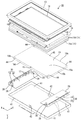
- FIG. 1 is an exploded perspective view showing a schematic configuration of a television receiver according to Embodiment 1 of the present invention. Exploded perspective view showing schematic configuration of liquid crystal display device
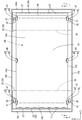
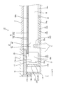
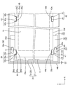
- the top view which shows the arrangement structure of the chassis, the heat radiating member, and the light-guide plate in the backlight apparatus with which a liquid crystal display device is equipped. Sectional view taken along line iv-iv in FIG. V-v sectional view of FIG.
- the top view which shows the state before the thermal expansion of the light-guide plate in a backlight apparatus.
- the top view which shows the state after the thermal expansion of the light-guide plate in a backlight apparatus.
- Sectional drawing which shows assembly
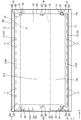
- the top view which shows the arrangement configuration of the chassis, the heat radiating member, and the light-guide plate in the backlight apparatus which concerns on Embodiment 3 of this invention.
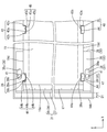
- the top view which shows the arrangement configuration of the chassis, the heat radiating member, and the light-guide plate in the backlight apparatus which concerns on Embodiment 4 of this invention.
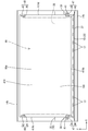
- the top view which shows the arrangement configuration of the chassis, the heat radiating member, and the light-guide plate in the backlight apparatus which concerns on Embodiment 5 of this invention.
- the top view which shows the arrangement configuration of the chassis, the heat radiating member, and the light-guide plate in the backlight apparatus which concerns on Embodiment 6 of this invention.
- FIGS. 1 A first embodiment of the present invention will be described with reference to FIGS.
- the liquid crystal display device 10 is illustrated.
- a part of each drawing shows an X-axis, a Y-axis, and a Z-axis, and the directions of the axes are drawn in common directions in the drawings.
- the upper side shown in FIG. 4 be a front side, and let the lower side of the figure be a back side.
- the television receiver TV includes a liquid crystal display device 10, front and back cabinets Ca and Cb that are accommodated so as to sandwich the liquid crystal display device 10, a power source P, a tuner T,
- the liquid crystal display device 10 is supported by the stand S in a state where the display surface of the liquid crystal display device 10 is along the vertical direction (Y-axis direction).
- the liquid crystal display device (display device) 10 has a horizontally long rectangular shape (rectangular shape, longitudinal shape) as a whole, and is accommodated in a vertically placed state.
- the liquid crystal display device 10 includes a liquid crystal panel 11 that is a display panel and a backlight device (illumination device) 12 that is an external light source, which are integrated by a frame-like bezel 13 or the like. Is supposed to be retained.
- the liquid crystal panel 11 has a horizontally long rectangular shape (rectangular shape, longitudinal shape) in a plan view, and a pair of glass substrates having excellent translucency are separated by a predetermined gap.
- the liquid crystal is sealed between both substrates.
- One substrate is provided with a switching element (for example, TFT) connected to a source wiring and a gate wiring orthogonal to each other, a pixel electrode connected to the switching element, an alignment film, and the like.
- a color filter in which colored portions such as R (red), G (green), and B (blue) are arranged in a predetermined arrangement, a counter electrode, and an alignment film.
- the liquid crystal panel 11 has a display area AA on the center side of the screen where an image can be displayed and a frame shape (frame shape) surrounding the display area AA on the outer peripheral edge side of the screen. It is divided into a non-display area NAA.
- the inner area surrounded by the alternate long and short dash line indicates the display area AA
- the outer area indicates the non-display area NAA.
- a polarizing plate is disposed on the outside of both substrates.
- the backlight device 12 includes a chassis 14 having a substantially box shape having a light emitting portion 14 c that opens toward the front side (light emitting side, liquid crystal panel 11 side), and light emitting from the chassis 14. And an optical member 15 arranged to cover the portion 14c. Further, in the chassis 14, there are an LED (Light Emitting Diode) 17 that is a light source, a light guide plate 19 that guides light from the LED 17 and guides it to the optical member 15 (liquid crystal panel 11), and the LED 17.
- a light source mounting unit 30 including a mounted LED substrate 18 and a heat radiating member 35 that radiates heat generated by the LEDs 17, and a frame 16 that holds the light guide plate 19 and the optical member 15 from the front side are provided.
- the backlight device 12 includes light source mounting units 30 in which LEDs 17 are arranged at both ends on the short side, and a light guide plate 19 is disposed on the center side between the LEDs 17 on both sides. This is a so-called edge light type (side light type). Below, each component of the backlight apparatus 12 is demonstrated.
- the chassis 14 is made of, for example, a metal plate such as an aluminum plate or an electrogalvanized steel plate (SECC). As shown in FIG. 2, the chassis 14 has a horizontally long bottom plate 14a and a length of the bottom plate 14a. A pair of side plates 14b rising from the outer ends on the side and short sides respectively.
- the long side direction of the chassis 14 (bottom plate 14a) coincides with the X-axis direction (horizontal direction), and the short side direction coincides with the Y-axis direction (vertical direction).
- the frame 16 and the bezel 13 can be screwed to the side plate 14b.
- the bottom plate 14a is provided with engaging portions 41 at its four corners to be engaged with mounting plate portions 32 of the light source mounting unit 30 described later.
- the bottom plate 14a is provided with a second protrusion 42 that fits with a second fitting portion 45 of the light guide plate 19 described later at the center in the X-axis direction.
- the configuration related to the engaging portion 41 and the second projecting portion 42 will be described in detail later.
- the optical member 15 has a horizontally long rectangular shape when viewed in a plane, like the liquid crystal panel 11 and the chassis 14.
- the optical member 15 is placed on the front side (light emitting side) of the light guide plate 19 and is interposed between the liquid crystal panel 11 and the light guide plate 19.
- the optical member 15 includes a diffusion plate 15a disposed on the back side and an optical sheet 15b disposed on the front side.
- the diffusing plate 15a has a structure in which a large number of diffusing particles are dispersed in a base material made of a substantially transparent synthetic resin having a predetermined thickness and has a function of diffusing transmitted light.
- the optical sheet 15b has a sheet shape that is thinner than the diffusion plate 15a, and two optical sheets 15b are laminated. Specific types of the optical sheet 15b include, for example, a diffusion sheet, a lens sheet, a reflective polarizing sheet, and the like, which can be appropriately selected and used.
- the frame 16 is formed in a frame shape (frame shape) extending along the outer peripheral edge portions of the optical member 15 and the light guide plate 19, and the outer peripheral edge of the optical member 15 and the light guide plate 19. It can be pressed from the front side over almost the entire circumference while facing the part.
- the frame 16 is made of a synthetic resin and has a light shielding property by having a surface with, for example, a black color.
- a first reflection sheet 20 for reflecting light is attached to the back surface of both short sides of the frame 16, that is, the surface facing the light guide plate 19 and the LED substrate 18 (LED 17). It has been.
- the first reflection sheet 20 has a size extending over almost the entire length of the short side portion of the frame 16, and covers the LED 17 side end portion and LED 17 group of the light guide plate 19 from the front side collectively. Is done. Further, the frame 16 can receive the outer peripheral edge of the liquid crystal panel 11 from the back side.
- the LED 17 has a configuration in which an LED chip is sealed with a resin material on a substrate portion fixed to the LED substrate 18.
- the LED chip mounted on the substrate unit has one main emission wavelength, and specifically, one that emits blue light in a single color is used.
- the resin material that seals the LED chip is dispersed and blended with a phosphor that emits a predetermined color when excited by the blue light emitted from the LED chip, and generally emits white light as a whole. It is said.
- the phosphor for example, a yellow phosphor that emits yellow light, a green phosphor that emits green light, and a red phosphor that emits red light are used in appropriate combination, or any one of them is used. It can be used alone.
- This LED 17 is of a so-called top surface light emitting type in which the top surface opposite to the mounting surface with respect to the LED substrate 18 is the light emitting surface 17a.
- the light source mounting unit 30 includes an LED substrate 18 and a heat radiating member 35.
- the light source mounting unit 30 has an L-shaped plate member as a whole, and has a light source arrangement plate portion. 31 and a mounting plate portion 32 that is bent from the light source arrangement plate portion 31.
- the light source mounting unit 30 has a posture in which the light source arrangement plate portion 31 is parallel to the Y-axis direction and the Z-axis direction, that is, a posture along the side plate 14b of the chassis 14, and the mounting plate portion 32 is in the Y-axis direction and X-axis direction. In a posture parallel to the bottom plate 14a, that is, a posture along the bottom plate 14a of the chassis 14. As shown in FIG.
- the light source mounting units 30 are respectively disposed at both ends of the chassis 14 in the X-axis direction, and the pair of light source mounting units 30 and 30 are opposed to each other with the light guide plate 19 interposed therebetween.
- the mounting plate portions 32 are arranged so as to face each other toward the inner side (center side of the chassis 14).
- the LED board 18 has a long and narrow plate shape extending along the short side direction (Y-axis direction) of the chassis 14, and the main plate surface thereof is in the Y-axis direction and the Z-axis direction. In parallel, that is, in a posture orthogonal to the plate surfaces of the liquid crystal panel 11 and the light guide plate 19.
- a pair of LED substrates 18 are arranged corresponding to both ends on the short side in the chassis 14.
- the LED 17 having the above-described configuration is surface-mounted on the light source mounting surface 18a facing the inner side, that is, the light guide plate 19 side, which is the main plate surface of the LED substrate 18.
- a plurality of LEDs 17 are arranged in a line (linearly) in parallel along the length direction (Y-axis direction) on the light source mounting surface 18 a of the LED substrate 18. Accordingly, it can be said that a plurality of LEDs 17 are arranged in parallel along the short side direction at both ends on the short side of the backlight device 12. Since the pair of LED substrates 18 are housed in the chassis 14 in such a posture that the light source mounting surfaces 18a are opposed to each other, the light emitting surfaces of the LEDs 17 respectively mounted on the LED substrates 18 are opposed to each other, The optical axis of each LED 17 substantially coincides with the Y-axis direction.
- the base material of the LED substrate 18 is made of a metal such as an aluminum material same as that of the chassis 14, and a wiring pattern (not shown) made of a metal film such as a copper foil is formed on the surface thereof via an insulating layer.
- the outermost surface is formed with a reflective layer (not shown) that exhibits white light with excellent light reflectivity.
- the LEDs 17 arranged in parallel on the LED substrate 18 are connected in series by this wiring pattern.
- insulating materials such as a ceramic, can also be used as a ceramic.
- the heat dissipating member 35 is made of a metal such as aluminum having excellent heat dissipating properties, and is formed by bending a plate-like member having an L shape in cross section and having a rectangular outer shape as shown in FIG. Yes.
- the heat dissipating member 35 has an extension 36 extending along the bottom plate 14 a of the chassis 14, a standing wall 37 rising from the extension 36 along the side plate 14 b of the chassis 14, and an opening on the plate surface of the extension 36.
- a first protrusion 39 protruding in a direction orthogonal to the plate surface of the extending part 36.
- the extending portion 36 has a rectangular shape in plan view and is sandwiched between the light guide plate 19 (light guide reflection sheet 22) and the bottom plate 14 a of the chassis 14.
- the length of the extending portion 36 is slightly smaller than the bottom plate 14a of the chassis 14 and larger than the light guide plate 19 in the Y-axis direction (the direction orthogonal to the displacement direction of the light incident surface 19b).
- An opening 38 is disposed at a position outside the portion 36 sandwiched between the light guide plates 19 in the portion 36.
- the length dimension of the extending portion 36 is about 1 ⁇ 4 of the length of the bottom plate 14a of the chassis 14 in the X-axis direction.
- the extending portion 36 has a main plate surface in contact with the inner surface of the bottom plate 14a, and can efficiently dissipate heat generated from each LED 17 to the bottom plate 14a of the chassis 14. Is done.
- the standing wall portion 37 is arranged between the side plate 14 b of the chassis 14 with a clearance that allows thermal expansion of the light guide plate 19 described later.
- the LED board 18 is attached to the board
- the substrate placement surface 37a is in thermal contact with the mounting surface 18b located on the opposite side of the light source mounting surface 18a of the LED substrate 18, and the heat generated with the lighting of the LED 17 is transmitted through the LED substrate 18. It is set as the structure which can heat-transfer to the standing wall part 37.
- “in contact with heat” means that the standing wall portion 37 and the LED substrate 18 may be in direct contact with each other, or may be in contact via an adhesive member having thermal conductivity.
- the light source arrangement plate part 31 is composed of the LED substrate 18 and the standing wall part 37, the LED 17 is arranged, and has a plate surface facing the light incident surface 19 b of the light guide plate 19 as a whole.
- the mounting plate portion 32 includes an extension portion 36, an opening portion 38, and a first protrusion 39, extends from the light source arrangement plate portion 31 toward the light guide plate 19, and the light source arrangement plate portion 31. Are attached to the light guide plate 19 so as to follow the displacement of the light incident surface 19b. A mounting configuration of the mounting plate portion 32 to the light guide plate 19 will be described in detail later.
- the light guide plate 19 is made of a synthetic resin material (for example, acrylic resin such as PMMA, polycarbonate, etc.) having a refractive index sufficiently higher than air and excellent in translucency. As shown in FIGS. 2 and 3, the light guide plate 19 has a horizontally long rectangular shape in a plan view as in the case of the liquid crystal panel 11 and the chassis 14, and has a plate shape larger in thickness than the optical member 15, The long side direction on the main plate surface coincides with the X-axis direction, the short side direction coincides with the Y-axis direction, and the plate thickness direction orthogonal to the main plate surface coincides with the Z-axis direction. As shown in FIG.
- the light guide plate 19 is disposed in the chassis 14 at a position directly below the liquid crystal panel 11 and the optical member 15, and has a pair of light sources attached to both ends of the short side of the chassis 14. They are arranged so as to be sandwiched between the units 30 in the X-axis direction. Therefore, the alignment direction of the LED 17 (light source mounting unit 30) and the light guide plate 19 coincides with the X-axis direction, whereas the alignment direction of the optical member 15 (liquid crystal panel 11) and the light guide plate 19 is the Z-axis direction. It is in agreement and both arrangement directions are orthogonal to each other.
- the light guide plate 19 has a function of introducing the light emitted from the LED 17 in the X-axis direction and raising and emitting the light toward the optical member 15 side (front side) while propagating the light inside. .
- the light guide plate 19 has a light emitting surface 19 a that emits internal light toward the optical member 15 and the liquid crystal panel 11 on the main plate surface facing the front side (a surface facing the optical member 15). Out of the peripheral end surfaces adjacent to the light emitting surface 19a, both end surfaces on the short side arranged along the Y-axis direction are opposed to the LED 17 with a predetermined space therebetween, and these are the LED 17 It becomes a pair of light-incidence surfaces 19b and 19b into which the light emitted from is incident. On the front side of the space held between the LED 17 and the light incident surface 19b, as shown in FIG.
- each light incident surface 19b is in a posture parallel to the Y-axis direction (LED 17 arrangement direction) and the Z-axis direction, that is, in a usage state of the television receiver TV (a state where the light emission surface 19a is aligned in the vertical direction). It is arranged in a posture along the vertical direction.
- the light guide plate 19 has a pair of side surfaces 19d and 19d, which are both end surfaces on the long side, on the sides of the light emitting surface 19a and the light incident surface 19b.
- a first fitting portion 44 is provided on the side surface 19d in the vicinity of the light incident surface 19b, and a second fitting portion 45 is provided at an intermediate position between the pair of light incident surfaces 19b and 19b, that is, at the center of the side surface 19d. Is provided.
- the structure which concerns on the 1st fitting part 44 and the 2nd fitting part 45 is demonstrated in detail later.
- the light guide plate 19 propagates through the back side of the light guide plate 19, that is, the bottom surface (the surface facing the bottom plate 14a of the chassis 14) 19c, which is the opposite side of the light emitting surface 19a.
- a light guide reflection sheet 22 that can reflect the light reaching the bottom surface 19c and rise up toward the front side, that is, the light emitting surface 19a side, is provided so as to cover almost the entire area.
- at least one of the light exit surface 19a of the light guide plate 19 and the bottom surface 19c on the opposite side thereof has a reflection portion (not shown) or an internal portion that reflects the internal light and prompts the light exit from the light exit surface 19a.
- the scattering part (not shown) that scatters the light of the light and promotes the light output from the light output surface 19a is patterned so as to have a predetermined in-plane distribution, so that the light emitted from the light output surface 19a is in-plane It is controlled to have a uniform distribution.
- the assembly configuration and assembly procedure of the chassis 14, the light source mounting unit 30, and the light guide plate 19 according to the present embodiment will be described (see FIG. 8).
- the assembly configuration will be described.
- the opening portions 38 of the attachment plate portion 32 are respectively provided at both ends of the extending portion 36 in the Y-axis direction. That is, one light source mounting unit 30 is provided with a pair of openings 38 and 38.
- the opening 38 is a through-hole penetrating the plate surface of the extending portion 36 and has a longitudinal shape in the X-axis direction (displacement direction of the light incident surface 19 b). Yes.
- the engagement portion 41 of the chassis 14 is provided in alignment with the opening 38 of the mounting plate portion 32.
- the pair of engaging portions 41, 41 located at one end in the X-axis direction is engaged with a pair of openings 38, 38 provided in one light source mounting unit 30. It is said that.
- the engaging portion 41 is configured to project in a cylindrical shape toward the front side in a direction orthogonal to the plate surface of the bottom plate 14 a of the chassis 14, and is integrally formed with the chassis 14.
- the protruding height of the engaging portion 41 is larger than the plate thickness of the extending portion 36 of the heat radiating member 35.
- the diameter of the engaging portion 41 is smaller than the hole diameter of the opening portion 38 in the longitudinal direction (X-axis direction) of the opening portion 38, and the hole diameter of the opening portion 38 in the short direction (Y-axis direction) of the opening portion 38. It is almost the same size.
- the first protrusions 39 of the mounting plate portion 32 are provided at both ends of the extending portion 36 in the Y-axis direction and inside the opening 38.
- the pair of first protrusions 39 are provided at a position where the light guide plate 19 is sandwiched in the Y-axis direction in one light source mounting unit 30.
- the first protrusion 39 is configured to protrude in a rib shape (block shape) toward the front side in a direction orthogonal to the plate surface of the extension portion 36. It is integrally molded.
- the first protrusion 39 has a rectangular shape in plan view, and has a longitudinal shape in the X-axis direction (the displacement direction of the light incident surface 19b).
- the protrusion height of the first protrusion 39 is approximately the same as the thickness of the light guide plate 19.
- the first fitting portion 44 of the light guide plate 19 is aligned with the first protrusions 39 of the mounting plate portion 32 at both ends in the X-axis direction for each of the pair of side surfaces 19d.
- Each is provided. That is, the light guide plate 19 is provided with a pair of first fitting portions 44, 44 corresponding to each of the pair of light source mounting units 30, 30, and a total of four first fitting portions 44 are provided. Is provided.
- the pair of first fitting portions 44, 44 located at one end in the X-axis direction are fitted with a pair of first protrusions 39, 39 provided in one light source mounting unit 30. Yes.
- the first fitting portion 44 is a cutout portion in which the light guide plate 19 is cut out in a rectangular shape in plan view, and the cutout shape is substantially the same as the outer shape of the first protrusion 39 having a rib shape (block shape). It is said that.
- the second protrusions 42 of the chassis 14 are provided at the center of the bottom plate 14 a in the X-axis direction and at both ends in the Y-axis direction.
- the pair of second protrusions 42 and 42 are provided at positions where the light guide plate 19 is sandwiched in the Y-axis direction.
- the second protrusion 42 is configured to protrude in a rib shape (block shape) toward the front side in a direction orthogonal to the plate surface of the bottom plate 14 a of the chassis 14, and is integrated with the chassis 14. Molded.
- the second protrusion 42 has a rectangular shape in plan view, and has a longitudinal shape in the X-axis direction (the direction of displacement of the light incident surface 19b).
- the projecting height of the second projecting portion 42 is approximately the same as the sum of the thickness of the extending portion 36 of the mounting plate portion 32 and the thickness of the light guide plate 19.
- the second fitting portion 45 of the light guide plate 19 is aligned with the second protrusion 42 of the chassis 14 at the center of the pair of side surfaces 19 d in the X-axis direction, respectively.
- the second fitting portion 45 is a cutout portion in which the light guide plate 19 is cut out in a rectangular shape in plan view, and the cutout shape is substantially the same as the outer shape of the second protrusion 42 forming a rib shape (block shape). It is said that.
- the light source mounting unit 30 is assembled to the chassis 14. Specifically, the light source mounting unit 30 is brought close to the chassis 14 from a direction orthogonal to the plate surface of the bottom plate 14 a of the chassis 14. Then, each of the pair of engaging portions 41, 41 positioned at one end portion of the chassis 14 in the X-axis direction is inserted into each of the pair of openings 38, 38 of the light source mounting unit 30. When the mounting plate portion 32 of the light source mounting unit 30 comes into contact with the bottom plate 14 a of the chassis 14, the end of the engaging portion 41 passes through the opening 38. At this time, as shown in FIG.
- the engaging portion 41 has a clearance C with respect to the X-axis direction (the displacement direction of the light incident surface 19 b) with the inner peripheral surface 38 a of the opening 38. It engages with the inner peripheral surface 38a, and engages with the mounting plate portion 32 in a state where the mounting plate portion 32 is allowed to move in the X-axis direction.
- the Y-axis direction the direction perpendicular to the displacement direction of the light incident surface 19b
- the light guide plate 19 is assembled to the chassis 14 and the pair of light source mounting units 30 and 30. Specifically, the light guide plate 19 is close to the chassis 14 and the pair of light source mounting units 30 and 30 in a direction orthogonal to the plate surface of the bottom plate 14a of the chassis 14 (direction orthogonal to the plate surface of the mounting plate portion 32). Let And while fitting the 2nd protrusion 42 of the chassis 14, and the 2nd fitting part 45 of the light-guide plate 19, the 1st protrusion 39 and the 1st fitting part of the light source attachment unit 30 (attachment plate part 32) are fitted. 44 is fitted.
- the second fitting portion 45 of the light guide plate 19 is fitted in the direction orthogonal to the plate surface of the chassis 14 with respect to the second protrusion 42 of the chassis 14.
- the inner surfaces 42a, 42a of the pair of second protrusions 42, 42 extend in the X-axis direction of the second fitting portion 45 so as to sandwich the light guide plate 19 therebetween. Abutting on the inner peripheral surface 45a, the movement of the light guide plate 19 in the Y-axis direction relative to the chassis 14 is restricted.
- both end surfaces (surfaces extending in the Y-axis direction) 42 b and 42 b in the X-axis direction of the second protrusion 42 are in the Y-axis direction of the second fitting portion 45 of the light guide plate 19.
- the extended inner peripheral surfaces 45b and 45b are hooked, and the movement of the light guide plate 19 in the X-axis direction with respect to the chassis 14 is restricted. That is, the light guide plate 19 is positioned with respect to the chassis 14 by the second fitting structure 48 of the second protrusion 42 and the second fitting portion 45.
- the first fitting portion 44 of the light guide plate 19 is orthogonal to the plate surface of the mounting plate portion 32 with respect to the first protrusion 39 of the light source mounting unit 30. Fit in the direction to be. Then, as shown in FIG. 6, in the Y-axis direction, the first fitting is performed so that the inner surfaces 39 a and 39 a of the pair of first protrusions 39 and 39 disposed on one light source mounting unit 30 sandwich the light guide plate 19.
- the light source mounting unit 30 is fixed to the light guide plate 19 by coming into contact with the inner peripheral surface 44 a extending in the X-axis direction of the joint portion 44.
- both end surfaces (surfaces extending in the Y-axis direction) 39b, 39b of the first protrusion 39 are in the Y-axis direction of the first fitting portion 44 of the light guide plate 19.
- the light source mounting unit 30 is fixed to the light guide plate 19 by being hooked on the extended inner peripheral surfaces 44 b and 44 b. That is, the light source mounting unit 30 is fixed to the light guide plate 19 by the first fitting structure 47 of the first protrusion 39 and the first fitting portion 44.
- the first fitting structure 47 and the second fitting structure 48 are further closer to the end than the LEDs 17 arranged on both ends of the group of LEDs 17 arranged intermittently in parallel in the Y-axis direction. It is arranged at a position shifted to the side opposite to the adjacent LED 17 side.
- the first fitting structure 47 and the second fitting structure 48 are fitted into the first fitting portion 44 and the second fitting portion 45 formed by cutting out the side surface 19d of the light guide plate 19 and the second fitting structure 48. It is composed of a first protrusion 39 and a second protrusion 42, and can be a hindrance to travel for light propagating in the light guide plate 19.
- the first fitting structure 47 and the second fitting structure 48 are arranged so as not to be opposed (offset) with respect to the LED 17 in the direction along the optical axis (X-axis direction), the LED 17 is led from the LED 17.
- Light that has entered the light plate 19 is less likely to hit the first fitting structure 47 and the second fitting structure 48, and light that propagates through the light guide plate 19 by the first fitting structure 47 and the second fitting structure 48.
- the optical path is not easily disturbed.
- the first fitting structure 47 and the second fitting structure 48 are arranged in the non-display area NAA so as not to exist in the display area AA in the liquid crystal panel 11. Thereby, it is possible to prevent a situation in which the first fitting structure 47 and the second fitting structure 48 are directly visually recognized by the user of the liquid crystal display device 10.
- This embodiment has the structure as described above, and its operation will be described next.
- the power source of the liquid crystal display device 10 is turned on and each LED 17 is turned on, each LED 17 generates heat, and the temperature in the backlight device 12 rises.
- thermal expansion occurs in the light guide plate 19, and the thermal expansion occurs from the fixing position of the light guide plate 19 with respect to the chassis 14, that is, the second fitting structure 48.
- the amount of extension in the horizontal direction accompanying thermal expansion in the light guide plate 19 is proportional to the distance from the second fitting structure 48 that is the base point of thermal expansion.
- the light incident surfaces 19b which are both side surfaces in the horizontal direction (X-axis direction) are displaced outward in the same direction as shown in FIG.
- the mounting plate portion 32 is fixed in the vicinity of the light incident surface 19b of the light guide plate 19
- the light source plate 19 is thermally expanded to cause the light source arrangement plate portion 31 to be on the light incident surface 19b of the light guide plate 19.
- each LED 17 moves in the horizontal direction together with the light source arrangement plate portion 31 by the same amount as the displacement of the light incident surface 19b of the light guide plate 19. Therefore, before and after thermal expansion and in the process, the gap between each LED 17 mounted on the light source arrangement plate portion 31 of the light source mounting unit 30 and the light incident surface 19b of the light guide plate 19, that is, the positional relationship in the horizontal direction is , Hardly changes and is always kept constant.
- the engaging portion 41 of the chassis 14 includes the opening 38 of the mounting plate portion 32 of the light source mounting unit 30.
- the light source mounting unit 30 can move with little rattling in the Y-axis direction, that is, the direction orthogonal to the displacement direction of the light incident surface 19b with respect to the chassis 14. ing. Thereby, the operation
- each LED 17 is periodically blinked, The time ratio with the extinguishing period is changed.
- the temperature in the backlight device 12 rises or falls, and when the temperature falls, the light guide plate 19 undergoes thermal contraction. . That is, the light guide plate 19 may be thermally contracted in a state where an image is displayed on the liquid crystal display device 10.
- the light incident surfaces 19b located at both ends in the horizontal direction are displaced inward in the same direction as shown in FIG.
- the mounting plate portion 32 is fixed in the vicinity of the light incident surface 19b of the light guide plate 19. Therefore, when the light incident surface 19b of the light guide plate 19 is displaced inward due to thermal contraction, the light source arrangement plate portion 31. Is moved following the inner side in the horizontal direction by substantially the same amount of displacement of the light incident surface 19 b of the light guide plate 19. Therefore, the gap between the LEDs 17 provided in the light source mounting unit 30 and the light incident surface 19b of the light guide plate 19, that is, the positional relationship in the horizontal direction can be almost changed before and after thermal contraction. Not always maintained in a constant state. Even during thermal contraction, the movement operation of the light source mounting unit 30 is smoothly guided by the opening 38 of the light source mounting unit 30 and the engaging portion 41 of the chassis 14 as in the case of thermal expansion.
- the backlight device 12 includes the LED 17, the light incident surface 19b that faces the LED 17 and receives light from the LED 17, and the light emission from which the light incident from the light incident surface 19b is emitted.
- a light source plate 19 having a surface 19a, and a light source mounting unit 30 having a plate member L-shaped in cross-sectional view, the LED 17 being disposed, and a light source arrangement plate portion having a plate surface facing the light incident surface 19b 31 and an attachment plate portion that extends from the light source arrangement plate portion 31 toward the light guide plate 19 and is attached to the light guide plate 19 so that the light source arrangement plate portion 31 can follow the displacement of the light incident surface 19b.
- the mounting plate portion 32 is sandwiched between the light guide plate 19 and attached.
- the bottom plate 14a is in contact with the plate surface of the portion 32, and the bottom plate 14a is engaged with the mounting plate portion 32 while allowing the light incident surface 19b of the mounting plate portion 32 to move in the displacement direction.
- a chassis 14 provided with 41.
- the distance between the LED 17 and the light incident surface 19b can be made constant.
- the clearance between the LED 17 and the light incident surface 19b set in consideration of thermal expansion or the like can be reduced.
- the distance between the LED 17 and the light guide plate 19 can be shortened, the amount of light traveling from the LED 17 to a region other than the light incident surface 19b of the light guide plate 19 can be reduced, and the luminance of the backlight device 12 can be reduced. Can be improved.
- the light guide plate 19 and the light source mounting unit 30 are respectively positioned with respect to the chassis 14, if the clearance between the LED 17 and the light incident surface 19 b is reduced, light is incident due to thermal expansion of the light guide plate 19. There is a possibility that the distance between the surface 19b and the LED 17 becomes small, and the light incident surface 19b presses the LED 17 in the displacement direction of the light incident surface 19b. And when the light-incidence surface 19b presses LED17 to a displacement direction, there exists a possibility that the electrical connection location of LED17 and the structural member of LED17 may be damaged. However, in the present embodiment, such a situation does not occur, and the clearance between the LED 17 and the light incident surface 19b can be sufficiently reduced.
- the light source mounting unit 30 since the light source mounting unit 30 includes the mounting plate portion 32 that contacts the bottom plate 14a of the chassis 14, the heat generated from the LED 17 can be efficiently radiated through the bottom plate 14a of the chassis 14, The thermal expansion itself of the light guide plate 19 can be reduced. Further, even when the light incident surface 19b is displaced due to the thermal expansion or the like, the chassis 14 allows the mounting plate portion 32 to move in the displacement direction of the light incident surface 19b. Since the engaging portion 41 to be engaged is provided, the light source mounting unit 30 is displaced while maintaining the engaged state with the engaging portion 41, and the displacement of the light source mounting unit 30 is stabilized. be able to.
- the light source arrangement plate portion 31 is configured to be able to follow the displacement of the light incident surface 19b, the fluctuation of the incident efficiency when the light from the LED 17 enters the light incident surface 19b is suppressed.
- the luminance of the light emitted from the light guide plate 19 can be stabilized.
- the incident efficiency when the light from the LED 17 is incident on the light incident surface 19b is small when the interval held between the LED 17 and the light incident surface 19b varies. If there is, it will fluctuate greatly.
- the setting value of the interval decreases as the narrowing of the frame of the liquid crystal display device 10 progresses, the variation rate of the incident efficiency when the interval varies tends to increase.
- the engaging portion 41 protrudes in a direction perpendicular to the plate surface of the bottom plate 14a of the chassis 14, so the engagement portion 41 is perpendicular to the plate surface of the bottom plate 14a with respect to the opening 38.
- the inner peripheral surface 38a of the opening 38 and the engaging portion 41 can be engaged with each other. For this reason, the mounting plate part 32 and the engaging part 41 can be assembled
- the engaging portion 41 has substantially the same diameter as the diameter of the opening 38 in the direction orthogonal to the displacement direction of the light incident surface 19b.
- the optical plate 19 can be restricted from moving in a direction orthogonal to the direction of displacement of the light incident surface 19b.
- the opening part 38 is distribute
- the first fitting portion 44 of the light guide plate 19 and the first protrusion 39 of the mounting plate portion 32 are fitted in a direction orthogonal to the plate surface of the mounting plate portion 32, so that the mounting plate By placing the light guide plate 19 on the portion 32, the first fitting portion 44 and the first protrusion 39 can be assembled.
- the light guide plate 19 can be assembled to the light source mounting unit 30 while the light source mounting unit 30 is housed in the chassis 14, and the backlight device 12 can be easily assembled.
- the second fitting portion 45 of the light guide plate 19 and the second protrusion of the chassis 14 are fitted in a direction orthogonal to the plate surface of the bottom plate 14a of the chassis 14, so that the bottom plate 14a
- the second fitting portion 45 and the second protrusion 42 can be assembled.
- the light guide plate 19 can be assembled to the chassis 14 in the process of bringing the light guide plate 19 close to the chassis 14 from the front side and housed in the chassis 14, and the backlight device 12 can be easily assembled. .
- the light source mounting unit 30 and the chassis 14 are fitted to the light guide plate 19 from the same direction. Therefore, if the light source mounting unit 30 and the chassis 14 are assembled, the light source mounting unit 30 and the chassis 14 and the light guide plate 19 can be assembled together, and the backlight device 12 can be easily assembled. It is.
- each of the pair of light incident surfaces 19b and 19b is displaced by thermal expansion or the like.
- the light guide plate 19 can be positioned with respect to the chassis 14 while allowing.
- the displacement of each of the pair of light incident surfaces 19b and 19b is uniform.
- the air warmed in the backlight device 12 tends to gather upward in the vertical direction, so that the temperature distribution in the backlight device 12 has a large displacement in the vertical direction, The displacement in the horizontal direction is assumed to be small. For this reason, if the pair of light incident surfaces 19b, 19b are arranged in a posture along the vertical direction, the pair of light incident surfaces 19b, 19b are disposed at both ends in the horizontal direction with little displacement of the temperature distribution. .
- LED17 can be mounted in the LED board 18 separate from the heat radiating member 35, and LED17 Easy to implement.
- the heat dissipating member 135 is made of metal such as aluminum having excellent heat dissipating properties and has a rectangular plate shape in plan view.
- the heat radiating member 135 includes an extending portion 136 that extends along the bottom plate 14a of the chassis 14, a substrate placement portion 137 to which the LED substrate 18 is attached, an opening 38 that opens on the plate surface of the extending portion 36, and an extension. And a first protrusion 39 protruding in a direction orthogonal to the plate surface of the existing portion 36.
- the extending portion 136 has a rectangular shape in plan view, and is sandwiched between the light guide plate 19 (light guide reflection sheet 22) and the bottom plate 14a of the chassis 14.
- the length of the extending portion 136 is slightly smaller than the bottom plate 14a of the chassis 14 and larger than the light guide plate 19 in the Y-axis direction (the direction orthogonal to the displacement direction of the light incident surface 19b).
- an opening 38 is disposed at a position outside the portion sandwiched between the light guide plates 19.
- An end portion of the extending portion 136 that is located on the opposite side of the light guide plate 19 is disposed with a clearance that allows thermal expansion of the light guide plate 19 between the side plate 14 b of the chassis 14.
- the extending portion 136 has a main plate surface in contact with the inner surface of the bottom plate 14a, and can efficiently transmit heat generated from each LED 17 to the bottom plate 14a of the chassis 14 to radiate heat. Is done.
- the board arrangement part 137 is provided in the plate surface of the extension part 136, and the mounting surface 118 b that is orthogonal to the light source mounting surface 18 a and extends in the arrangement direction of the LEDs 17 is attached to the LED board 18. It is said.
- the board placement portion 137 is in thermal contact with the mounting surface 118b of the LED board 18 and can transfer heat generated by the lighting of the LED 17 to the extending portion 36 via the LED board 18. It is configured.
- “contacting heat transfer” means that the substrate placement portion 137 and the mounting surface 118b of the LED substrate 18 may be in direct contact, or may be in contact via an adhesive member having thermal conductivity. May be.
- the light source arrangement plate part 131 is configured by the LED substrate 18, the LED 17 is disposed, and has a plate surface facing the light incident surface 19 b of the light guide plate 19.
- the mounting plate portion 132 includes a portion of the extending portion 136 that is closer to the light guide plate 19 than the substrate placement portion 137, an opening portion 38, and a first protrusion 39, and the light source placement plate portion 131 (LED substrate). 18) extends toward the light guide plate 19, and the light source arrangement plate portion 131 is attached to the light guide plate 19 so as to follow the displacement of the light incident surface 19b.
- the heat radiating member 135 since the heat radiating member 135 has a flat plate shape, it is not necessary to bend the plate material in forming the heat radiating member 135, and the light source mounting unit 130 that requires accuracy in dimensional design can be easily manufactured. .
- the heat dissipating member 235 is made of a metal such as aluminum having excellent heat dissipating properties, and is formed by bending a plate-like member having an L shape in cross section and having a rectangular outer shape.
- the heat radiating member 235 includes an extending portion 36 extending along the bottom plate 14 a of the chassis 14, a standing wall portion 37 rising from the extending portion 36 along the side plate 14 b of the chassis 14, and orthogonal to the plate surface of the extending portion 36. And a first protrusion 39 that protrudes in the direction of the movement.
- the heat dissipation member 235 is different from the heat dissipation member 35 of the first embodiment in that the opening 38 is not provided.
- the mounting plate portion 232 includes an extending portion 36 and a first protrusion 39, extends from the light source arrangement plate portion 31 toward the light guide plate 19, and the light source arrangement plate portion 31 is the light incident surface 19b. It is attached to the light guide plate 19 so as to be able to follow the displacement.
- the mounting plate portion 232 has a rectangular shape in plan view, and has a pair of sides 238 and 238 along the displacement direction of the light incident surface 19b.
- the engaging portion 241 of the chassis 14 is provided in alignment with the pair of sides 238 and 238 of the mounting plate portion 32. Of the four engaging portions 241, a pair of engaging portions 241, 241 located at one end in the X-axis direction engage with a pair of sides 238, 238 provided in one light source mounting unit 230. Has been.
- the engaging portion 241 is configured to protrude in a rib shape toward the front side in a direction orthogonal to the plate surface of the bottom plate 14 a of the chassis 14, and is integrally formed with the chassis 14.
- the pair of engaging portions 241 and 241 are arranged apart from each other by the same length as the length of the mounting plate portion 232 in the Y-axis direction (direction orthogonal to the displacement direction of the light incident surface 19b).
- the mounting plate portion 232 is disposed between the pair of engaging portions 241 and 241, whereby the engaging portion 241 is engaged with the mounting plate portion 232, and the light source mounting unit is attached to the chassis 14. 230 and the light guide plate 19 can be restricted from moving in a direction orthogonal to the displacement direction of the light incident surface 19b.
- Embodiment 4 of the present invention will be described with reference to FIG.
- a light guide plate 319 in which the arrangement of the pair of light incident surfaces 319b and 319b is changed is shown.
- action, and effect similar to above-described embodiment is abbreviate
- the pair of light incident surfaces 319b and 319b of the light guide plate 319 is in a posture parallel to the X-axis direction and the Z-axis direction, that is, in a usage state of the television receiver TV (a state where the light emitting surface 19a is aligned in the vertical direction). It is arranged in a posture along the horizontal direction.
- a pair of light source mounting units 30 in which the LEDs 17 are arranged are arranged on the upper and lower sides in the vertical direction with the light guide plate 319 interposed therebetween.
- the light incident surface 319b extends in the horizontal direction, and the in-plane displacement can be made uniform for each of the pair of light incident surfaces 319b and 319b.
- the air warmed in the backlight device 12 is likely to gather upward in the vertical direction, and the temperature distribution in the backlight device 12 has a large displacement in the vertical direction, while being horizontal. There is little displacement in the direction. Therefore, if the pair of light incident surfaces 319b and 319b are arranged in a posture along the horizontal direction, the temperature distribution in the surface of each of the pair of light incident surfaces 319b and 319b can be made uniform.
- a fifth embodiment of the present invention will be described with reference to FIG.
- a light guide plate 419 in which a light incident surface 419b is disposed only on one end side of the light guide plate 19 is shown.
- action, and effect similar to above-described embodiment is abbreviate
- the light incident surface 419b of the light guide plate 419 follows the horizontal direction in a posture parallel to the X-axis direction and the Z-axis direction, that is, in a usage state of the television receiver TV (a state in which the light emitting surface 19a is along the vertical direction). It is arranged only on the lower side in the vertical direction. On the other hand, the light source mounting unit 30 in which the LEDs 17 are arranged is arranged on the lower side in the vertical direction.
- the light guide plate 419 has a pair of side surfaces 419d that are both end surfaces on the short side arranged along the Y-axis direction on the sides of the light emitting surface 19a and the light incident surface 419b.
- a first fitting portion 44 is provided in the vicinity of the light incident surface 419b
- a second fitting portion 45 is provided on the upper side in the vertical direction (end portion in the Y-axis direction).
- the second protrusions 42 of the chassis 14 are provided on the upper side in the vertical direction of the bottom plate 14a and at both ends in the X-axis direction.
- Embodiment 6 of the present invention will be described with reference to FIG.
- the shapes of the first protrusion 539 and the second protrusion 542, and the shapes of the first fitting part 44 and the second fitting part 45, in which the shapes of the first protrusion 39 and the second protrusion 42 are changed, are described.
- the 1st fitting part 544 and the 2nd fitting part 545 which changed are shown.
- action, and effect similar to above-described embodiment is abbreviate
- the first protrusion 539 is configured to protrude toward the front side in a direction orthogonal to the plate surface of the extension part 36, and is integrally formed with the extension part 36.
- the first protrusions 539 are U-shaped in plan view, and the pair of first protrusions 539 and 539 are arranged in a posture in which the opening ends face each other.
- the first fitting portion 544 is a protruding portion protruding in a block shape from the side surface 19d of the light guide plate 19, and the protruding outer surface is fitted to the inner surface of the first protruding portion 539 having a U-shape. ing.
- the second protrusion 542 is configured to protrude toward the front side in a direction orthogonal to the plate surface of the bottom plate 14 a of the chassis 14, and is integrally formed with the chassis 14. Similar to the first protrusion 539, the second protrusion 542 has a U-shape in plan view, and the pair of second protrusions 542, 542 are arranged in a posture in which the opening ends face each other.
- the second fitting portion 545 is a protruding portion protruding in a block shape from the side surface 19d of the light guide plate 19, and the protruding outer surface is fitted to the inner surface of the second protruding portion 542 having a U-shape. ing.
- the present invention is not limited to the embodiments described with reference to the above description and drawings.
- the following embodiments are also included in the technical scope of the present invention.
- the light source mounting unit is exemplified by an LED substrate and a heat radiating member.
- the LED may be mounted on a single light source mounting unit.
- the engagement portion 41 is illustrated as engaging with the opening 38 of the attachment plate portion 32.
- the engagement portion 241 is a pair of attachment plate portions 232.
- side 238,238 was illustrated, the aspect in which an engaging part engages with an attachment board part is not restricted to this.
- the engaging portion may be provided in a groove shape on the bottom plate of the chassis, and the protrusion provided on the mounting plate portion may be engaged with the groove-like engaging portion.
- one light source mounting unit is shown in which a pair of the engaging portion 41 and the opening portion 38 are provided, but each of the engaging portion 41 and the opening portion 38 is provided one by one. It may be provided, and three or more may be provided.
- the first fitting structure 47 is exemplified as a configuration for fixing the mounting plate portion to the light guide plate.
- the mounting plate portion is guided through a screw or an adhesive layer, for example. It may be fixed to the light plate.
- the second fitting structure 48 is exemplified as a configuration for positioning the light guide plate with respect to the chassis, but the positioning configuration is not limited thereto.
- the color part of the color filter included in the liquid crystal panel is exemplified by three colors of R, G, and B.
- the color part may be four or more colors.
- an LED is used as the light source.
- other light sources such as an organic EL can be used.
- a TFT is used as a switching element of a liquid crystal display device.
- the present invention can also be applied to a liquid crystal display device using a switching element other than TFT (for example, a thin film diode (TFD)).
- a switching element other than TFT for example, a thin film diode (TFD)
- the present invention can also be applied to a liquid crystal display device for monochrome display.
- the liquid crystal display device using the liquid crystal panel as the display panel has been exemplified.
- the present invention can also be applied to display devices using other types of display panels.
- the television receiver provided with the tuner is exemplified.
- the present invention can be applied to a display device that does not include the tuner.
- SYMBOLS 10 Liquid crystal display device (display device), 11 ... Liquid crystal panel (display panel), 12 ... Backlight device (illumination device), 14 ... Chassis, 14a ... Bottom plate, 17 ... LED (light source), 17a ... Light emission surface, 18 ... LED substrate (light source board), 18a ... Light source mounting surface, 18b, 118b ... Mounting surface, 19, 319, 419 ... Light guide plate, 19a ... Light emitting surface, 19b, 319b, 419b ... Light incident surface, 19c ... Bottom surface, 19d, 419d ... side, 30, 130, 230 ... light source mounting unit, 31, 131 ...
Landscapes
- Physics & Mathematics (AREA)
- General Physics & Mathematics (AREA)
- Optics & Photonics (AREA)
- Nonlinear Science (AREA)
- Mathematical Physics (AREA)
- Chemical & Material Sciences (AREA)
- Crystallography & Structural Chemistry (AREA)
- Planar Illumination Modules (AREA)
Abstract
本発明に係るバックライト装置12は、LED17と、光入射面19bと光出射面19aとを有する導光板19と、板部材を断面視L字状にした形の光源取付ユニット30であって、LED17が配され、光入射面19bと対向する板面を有する光源配置板部31と、光源配置板部31から導光板19に向かって延在し、光源配置板部31が光入射面19bの変位に追従可能なように導光板19に対して取り付けられてなる取付板部32と、を有する光源取付ユニット30と、光源取付ユニット30及び導光板19を収容するシャーシ14であって、導光板19との間に取付板部32を挟みこむとともに取付板部32の板面に接する底板14aを有し、底板14aには、取付板部32の光入射面19bの変位方向への移動を許容した状態で取付板部32に係合される係合部41が設けられているシャーシ14と、を備える。
Description
本発明は、照明装置、表示装置、及びテレビ受信装置に関する。
近年、テレビ受信装置をはじめとする画像表示装置の表示素子は、従来のブラウン管から液晶パネルやプラズマディスプレイパネルなどの薄型の表示パネルに移行しつつあり、画像表示装置の薄型化を可能としている。液晶表示装置は、これに用いる液晶パネルが自発光しないため、別途に照明装置としてバックライト装置を必要としており、バックライト装置はその機構によって直下型とエッジライト型とに大別されている。液晶表示装置の一層の薄型化を実現するには、エッジライト型のバックライト装置を用いるのが好ましく、その一例として下記特許文献1に記載されたものが知られている。
特許文献1に記載されたものでは、光源と、アクリル製の第1の導光板と当該第1の導光板よりガラス転移温度が高いポリカーボネート製の第2の導光板とを備え、第1の導光板の入射面と光源との間に第2の導光板が配されている面状光源装置が開示されている。そして、当該面状光源装置において、光源と第2の導光板の入射面が近いほど光利用効率が高いとの開示がなされている。
(発明が解決しようとする課題)
しかしながら、上記した特許文献1の構成では、導光板に熱膨張が生じた場合に、第2の導光板が光源に干渉する虞がある。すなわち、ポリカーボネートはアクリルよりガラス転移温度が高いものの、熱膨張率についてはアクリルとほぼ同等であり、第2の導光板及び第1の導光板の熱膨張により、第2の導光板の入射面が光源側に変位する。ここで、光源は、当該光源と導光板とを収容する下筐体(シャーシ)に対して位置決めされている。このため、光利用効率を高めるべく光源と第2の導光板の入射面とのクリアランスを小さくした場合には、導光板の熱膨張により第2の導光板の入射面が光源を押圧し、光源の電気的な接続箇所や光源の構成部材が破損する虞がある。
しかしながら、上記した特許文献1の構成では、導光板に熱膨張が生じた場合に、第2の導光板が光源に干渉する虞がある。すなわち、ポリカーボネートはアクリルよりガラス転移温度が高いものの、熱膨張率についてはアクリルとほぼ同等であり、第2の導光板及び第1の導光板の熱膨張により、第2の導光板の入射面が光源側に変位する。ここで、光源は、当該光源と導光板とを収容する下筐体(シャーシ)に対して位置決めされている。このため、光利用効率を高めるべく光源と第2の導光板の入射面とのクリアランスを小さくした場合には、導光板の熱膨張により第2の導光板の入射面が光源を押圧し、光源の電気的な接続箇所や光源の構成部材が破損する虞がある。
本発明は上記のような事情に基づいて完成されたものであって、導光板が光源に干渉することを抑制し、照明装置の輝度を高めることを目的とする。
(課題を解決するための手段)
上記課題を解決するために、本発明の照明装置は、光源と、前記光源に対向するとともに前記光源からの光が入射する光入射面と、当該光入射面から入射した光が出射する光出射面とを有する導光板と、板部材を断面視L字状にした形の光源取付ユニットであって、前記光源が配され、前記光入射面と対向する板面を有する光源配置板部と、前記光源配置板部から前記導光板に向かって延在し、前記光源配置板部が前記光入射面の変位に追従可能なように前記導光板に対して取り付けられてなる取付板部と、を有する光源取付ユニットと、前記光源取付ユニット及び前記導光板を収容するシャーシであって、前記導光板との間に前記取付板部を挟みこむとともに前記取付板部の板面に接する底板を有し、前記底板には、前記取付板部の前記光入射面の変位方向への移動を許容した状態で前記取付板部に係合される係合部が設けられているシャーシと、を備える。
上記課題を解決するために、本発明の照明装置は、光源と、前記光源に対向するとともに前記光源からの光が入射する光入射面と、当該光入射面から入射した光が出射する光出射面とを有する導光板と、板部材を断面視L字状にした形の光源取付ユニットであって、前記光源が配され、前記光入射面と対向する板面を有する光源配置板部と、前記光源配置板部から前記導光板に向かって延在し、前記光源配置板部が前記光入射面の変位に追従可能なように前記導光板に対して取り付けられてなる取付板部と、を有する光源取付ユニットと、前記光源取付ユニット及び前記導光板を収容するシャーシであって、前記導光板との間に前記取付板部を挟みこむとともに前記取付板部の板面に接する底板を有し、前記底板には、前記取付板部の前記光入射面の変位方向への移動を許容した状態で前記取付板部に係合される係合部が設けられているシャーシと、を備える。
本発明においては、光源配置板部が光入射面の変位に追従可能な構成とされているから、光源と光入射面との距離を一定にすることができ、導光板の熱膨張等を考慮して設定される光源と光入射面との間のクリアランスを低減することができる。このため、光源と導光板との距離を短くすることができ、光源から導光板の入射面以外の領域に進行する光の量を低減することができ、照明装置の輝度を上昇することができる。
さらに、本願発明においては、光源取付ユニットはシャーシの底板に接する取付板部を備えるから、光源から発生した熱をシャーシの底板を介して効率よく放熱することができ、導光板の熱膨張自体を低減することができる。さらに、当該熱膨張等による光入射面の変位が生じた場合においても、シャーシには当該取付板部の光入射面の変位方向への移動を許容した状態で取付板部に係合される係合部が設けられているから、光源取付ユニットは係合部との係合状態を維持しつつ変位することとなり、光源取付ユニットの変位を安定したものとすることができる。
上記構成において、前記取付板部には、開口部が設けられており、前記係合部は、前記底板の板面と直交する方向に突出するとともに、前記光入射面の変位方向について前記開口部の内周面との間にクリアランスを有して、当該内周面に係合されてなるものとすることができる。
このような構成とすれば、開口部に対して係合部を底板の板面と直交する方向に挿入して、内周面と係合部とを係合させることができる。このため、底板に対して光源取付ユニットを載置することにより、開口部と係合部とを組み付けることができる。
上記構成において、前記係合部は、前記光入射面の変位方向と直交する方向について前記開口部の径とほぼ同じ径とされてなるものとすることができる。
このような構成とすれば、シャーシに対し光源取付ユニット及び導光板が、光入射面の変位方向と直交する方向へ移動することを規制することができる。
上記構成において、前記取付板部は、前記光入射面の変位方向と直交する方向について、前記導光板より長い寸法とされており、前記開口部は、前記取付板部のうち前記導光板に挟みこまれる部分より外側の位置に配されているものとすることができる。
このような構成とすれば、係合部と導光板とが干渉することがなく、開口部と係合部との組み付けが容易である。
上記構成において、前記導光板は、前記光入射面及び前記光出射面の側方に配される側面と、前記側面のうち前記光入射面近傍に配され、前記光源取付ユニットと嵌合する第1嵌合部と、を有してなり、前記取付板部は、前記取付板部の板面と直交する方向に突出するとともに、前記第1嵌合部と前記取付板部の板面と直交する方向に嵌合する第1突部を有してなるものとすることができる。
このような構成とすれば、第1嵌合部と第1突部とは取付板部の板面と直交する方向に嵌合するから、取付板部に対して導光板を載置することにより、第1嵌合部と第1突部とを組み付けることができる。
上記構成において、前記導光板は、前記光入射面及び前記光出射面の側方に配される側面と、前記側面に配され、前記シャーシと嵌合する第2嵌合部と、を有してなり、前記底板には、前記底板の板面と直交する方向に突出するとともに、前記第2嵌合部と前記底板の板面と直交する方向に嵌合する第2突部が設けられているものとすることができる。
このような構成とすれば、第2嵌合部と第2突部とは底板の板面と直交する方向に嵌合するから、底板に対して導光板を載置することにより、第2嵌合部と第2突部とを組み付けることができる。
上記構成において、前記光源は、前記導光板を挟んだ位置に一対、互いに対向するよう配されており、前記導光板は、一対の前記光源の各々とそれぞれ対向するように配された一対の前記光入射面有し、前記第2嵌合部は、前記一対の前記光入射面の中間に配されているものとすることができる。
このような構成とすれば、一対の光入射面の各々について、熱膨張等による変位を許容しつつ、導光板の位置決めをすることができる。
上記構成において、前記導光板は、前記一対の前記光入射面を鉛直方向に沿わせた姿勢で配置されているものとすることができる。
このような構成とすれば、一対の光入射面の各々が水平方向の両端部に配されることとなり、一対の光入射面の各々の変位を均一なものとすることができる。
上記構成において、前記導光板は、前記光入射面を水平方向に沿わせた姿勢で配置されているものとすることができる。
このような構成とすれば、光入射面が水平方向に延設されることとなり、光入射面の面内の変位を均一なものとすることができる。
上記構成において、前記取付板部は、矩形状をなし、前記光入射面の変位方向に沿う一対の辺を有しており、前記係合部は、前記底板の板面と直交する方向に突出するとともに前記一対の辺の各々に当接するように一対設けられているものとすることができる。
このような構成とすれば、一対の係合部の間に取付板部を配することにより、取付板部と係合部とを組み付け、シャーシに対し光源取付ユニット及び導光板が、光入射面の変位方向と直交する方向へ移動することを規制することができる。
上記構成において、前記光源は、光源基板に実装されており、前記光源取付ユニットは、前記光源基板と当該光源基板と伝熱的に接する放熱部材とで構成されてなるものとすることができる。
このような構成とすれば、光源を放熱部材とは別体の光源基板に実装することができ、光源の実装が容易である。
次に、上記課題を解決するために、本発明の表示装置は、上記記載の照明装置と、前記照明装置からの光を利用して表示を行う表示パネルとを備える。
このような表示装置によると、表示パネルに対して光を供給する照明装置の輝度が高いものとされているから、表示品質の優れた表示を実現することが可能となる。
前記表示パネルとしては液晶パネルを例示することができる。このような表示装置は液晶表示装置として、種々の用途、例えばテレビやパソコンのディスプレイ等に適用でき、特に大型画面用として好適である。
(発明の効果)
本発明によれば、照明装置の輝度を高めることができる。
本発明によれば、照明装置の輝度を高めることができる。
<実施形態1>
本発明の実施形態1を図1から図8によって説明する。本実施形態では、液晶表示装置10について例示する。なお、各図面の一部にはX軸、Y軸及びZ軸を示しており、各軸方向が各図面において共通の方向となるように描かれている。また、図4に示す上側を表側とし、同図下側を裏側とする。
本発明の実施形態1を図1から図8によって説明する。本実施形態では、液晶表示装置10について例示する。なお、各図面の一部にはX軸、Y軸及びZ軸を示しており、各軸方向が各図面において共通の方向となるように描かれている。また、図4に示す上側を表側とし、同図下側を裏側とする。
本実施形態に係るテレビ受信装置TVは、図1に示すように、液晶表示装置10と、当該液晶表示装置10を挟むようにして収容する表裏両キャビネットCa,Cbと、電源Pと、チューナーTと、スタンドSとを備えて構成されており、スタンドSによって液晶表示装置10の表示面を鉛直方向(Y軸方向)に沿わせた状態で支持されている。液晶表示装置(表示装置)10は、全体として横長の方形(矩形状、長手状)をなし、縦置き状態で収容されている。この液晶表示装置10は、図2に示すように、表示パネルである液晶パネル11と、外部光源であるバックライト装置(照明装置)12とを備え、これらが枠状のベゼル13などにより一体的に保持されるようになっている。
液晶パネル11は、図2に示すように、平面に視て横長の方形(矩形状、長手状)をなしており、透光性に優れた一対のガラス製の基板が所定のギャップを隔てた状態で貼り合わせられるとともに、両基板間に液晶が封入された構成とされる。一方の基板には、互いに直交するソース配線とゲート配線とに接続されたスイッチング素子(例えばTFT)と、そのスイッチング素子に接続された画素電極、さらには配向膜等が設けられ、他方の基板には、R(赤色),G(緑色),B(青色)等の各着色部が所定配列で配置されたカラーフィルタや対向電極、さらには配向膜等が設けられている。この液晶パネル11は、図3に示すように、画面中央側にあって画像が表示可能な表示領域AAと、画面外周端側にあって表示領域AAの周りを取り囲む枠状(額縁状)をなす非表示領域NAAとに区分されている。なお、図3において一点鎖線で囲った内側の領域が表示領域AAを示し、外側の領域が非表示領域NAAを示している。また、両基板の外側には偏光板が配されている。
バックライト装置12は、図2に示すように、表側(光出射側、液晶パネル11側)に向けて開口する光出射部14cを有した略箱型をなすシャーシ14と、シャーシ14の光出射部14cを覆うようにして配される光学部材15とを備える。さらに、シャーシ14内には、光源であるLED(Light Emitting Diode:発光ダイオード)17と、LED17からの光を導光して光学部材15(液晶パネル11)へと導く導光板19と、LED17が実装されたLED基板18とLED17で生じた熱を放熱する放熱部材35とで構成される光源取付ユニット30と、導光板19及び光学部材15を表側から押さえるフレーム16とが備えられる。そして、このバックライト装置12は、その短辺側の両端部に、LED17が配された光源取付ユニット30をそれぞれ備えるとともに、両側のLED17間に挟まれた中央側に導光板19を配置してなる、いわゆるエッジライト型(サイドライト型)とされている。以下では、バックライト装置12の各構成部品について説明する。
シャーシ14は、例えばアルミニウム板や電気亜鉛めっき綱板(SECC)などの金属板からなり、図2に示すように、液晶パネル11と同様に横長の方形状をなす底板14aと、底板14aにおける長辺側及び短辺側の各外端からそれぞれ一対ずつ立ち上がる側板14bとからなる。シャーシ14(底板14a)は、その長辺方向がX軸方向(水平方向)と一致し、短辺方向がY軸方向(鉛直方向)と一致している。側板14bには、フレーム16及びベゼル13がねじ止め可能とされる。底板14aには、その四隅に、後述する光源取付ユニット30の取付板部32に係合される係合部41が設けられている。さらに、底板14aには、X軸方向の中央部に、後述する導光板19の第2嵌合部45と嵌合する第2突部42が設けられている。係合部41と第2突部42に係る構成については、後に詳しく説明する。
光学部材15は、図2に示すように、液晶パネル11及びシャーシ14と同様に平面に視て横長の方形状をなしている。光学部材15は、導光板19の表側(光出射側)に載せられていて液晶パネル11と導光板19との間に介在して配される。光学部材15は、裏側に配される拡散板15aと、表側に配される光学シート15bとから構成される。拡散板15aは、所定の厚みを持つほぼ透明な合成樹脂製で板状をなす基材内に拡散粒子を多数分散して設けた構成とされ、透過する光を拡散させる機能を有する。光学シート15bは、拡散板15aと比べると板厚が薄いシート状をなしており、2枚が積層して配されている。具体的な光学シート15bの種類としては、例えば拡散シート、レンズシート、反射型偏光シートなどがあり、これらの中から適宜に選択して使用することが可能である。
フレーム16は、図2に示すように、光学部材15及び導光板19の外周縁部に沿って延在する枠状(額縁状)に形成されており、光学部材15及び導光板19の外周縁部に対して対向状をなすとともにほぼ全周にわたって表側から押さえることが可能とされる。このフレーム16は、合成樹脂製とされるとともに、表面が例えば黒色を呈する形態とされることで、遮光性を有するものとされる。フレーム16のうち両短辺部分における裏側の面、つまり導光板19及びLED基板18(LED17)との対向面には、図4に示すように、光を反射させる第1反射シート20がそれぞれ取り付けられている。第1反射シート20は、フレーム16の短辺部分におけるほぼ全長にわたって延在する大きさを有しており、導光板19におけるLED17側の端部やLED17群などを一括して表側から覆うものとされる。また、フレーム16は、液晶パネル11における外周縁部を裏側から受けることができる。
LED17は、図5に示すように、LED基板18に固着される基板部上にLEDチップを樹脂材により封止した構成とされる。基板部に実装されるLEDチップは、主発光波長が1種類とされ、具体的には、青色を単色発光するものが用いられている。その一方、LEDチップを封止する樹脂材には、LEDチップから発せられた青色の光により励起されて所定の色を発光する蛍光体が分散配合されており、全体として概ね白色光を発するものとされる。なお、蛍光体としては、例えば黄色光を発光する黄色蛍光体、緑色光を発光する緑色蛍光体、及び赤色光を発光する赤色蛍光体の中から適宜組み合わせて用いたり、またはいずれか1つを単独で用いることができる。このLED17は、LED基板18に対する実装面とは反対側の頂面が発光面17aとなる、いわゆる頂面発光型とされている。
光源取付ユニット30は、図2及び図5に示すように、LED基板18と放熱部材35とで構成されており、全体として板部材を断面視L字状にした形をなし、光源配置板部31と、光源配置板部31から折れ曲がる取付板部32とで構成されている。光源取付ユニット30は、光源配置板部31をY軸方向及びZ軸方向に平行した姿勢、つまりシャーシ14の側板14bに沿わせる姿勢で、また、取付板部32をY軸方向及びX軸方向に平行した姿勢、つまりシャーシ14の底板14aに沿わせる姿勢で、シャーシ14内に収容されている。光源取付ユニット30は、図4に示すように、シャーシ14のX軸方向の両端部にそれぞれ配されており、一対の光源取付ユニット30,30が、導光板19を挟んで対向状をなし、互いに取付板部32を内側(シャーシ14の中央部側)に向けた姿勢で配されている。
LED基板18は、図2及び図5に示すように、シャーシ14の短辺方向(Y軸方向)に沿って延在する細長い板状をなすとともに、その主板面をY軸方向及びZ軸方向に平行した姿勢、つまり液晶パネル11及び導光板19の板面と直交させた姿勢で配されている。LED基板18は、シャーシ14内における短辺側の両端部に対応して一対配される。LED基板18の主板面であって内側、つまり導光板19側を向いた光源実装面18aには、上記した構成のLED17が表面実装されている。LED17は、LED基板18の光源実装面18aにおいて、その長さ方向(Y軸方向)に沿って複数が一列に(直線的に)並列配置されている。従って、LED17は、バックライト装置12における短辺側の両端部においてそれぞれ短辺方向に沿って複数ずつ並列配置されていると言える。一対のLED基板18は、光源実装面18aが互いに対向状をなす姿勢でシャーシ14内に収容されているので、両LED基板18にそれぞれ実装された各LED17の発光面が対向状をなすとともに、各LED17における光軸がY軸方向とほぼ一致する。
また、LED基板18の基材は、シャーシ14と同じアルミ系材料などの金属製とされ、その表面に絶縁層を介して銅箔などの金属膜からなる配線パターン(図示せず)が形成され、さらには最外表面には、光の反射性に優れた白色を呈する反射層(図示せず)が形成された構成とされる。この配線パターンによりLED基板18上に並列配置された各LED17同士が直列に接続されている。なお、LED基板18の基材に用いる材料としては、セラミックなどの絶縁材料を用いることも可能である。
放熱部材35は、放熱性に優れたアルミニウム等の金属製とされ、図5に示すように、断面視L字状をなし、矩形の外形をなす板状部材を曲げ加工することで形成されている。放熱部材35は、シャーシ14の底板14aに沿って延在する延在部36と、延在部36からシャーシ14の側板14bに沿って立ち上がる立壁部37と、延在部36の板面に開口する開口部38と、延在部36の板面と直交する方向に突出する第1突部39とを備える。次に、延在部36と立壁部37に係る構成について説明するものとし、開口部38と第1突部39に係る構成については後に詳しく説明する。
延在部36は、図3に示すように、平面視矩形状をなし、導光板19(導光反射シート22)とシャーシ14の底板14aとの間に挟みこまれるものとされている。延在部36の長さ寸法は、Y軸方向(光入射面19bの変位方向と直交する方向)について、シャーシ14の底板14aよりやや小さく、導光板19より大きいものとされており、延在部36のうち、導光板19に挟みこまれる部分より外側の位置に開口部38が配されている。また、延在部36の長さ寸法は、X軸方向について、シャーシ14の底板14aの長さの1/4程度の長さとされている。延在部36は、主板面が底板14aの内面に接するものとされており、各LED17から発せられた熱をシャーシ14の底板14aに対して効率よく伝達して放熱を図ることができるものとされる。
立壁部37は、図5に示すように、シャーシ14の側板14bとの間に、後述する導光板19の熱膨張を許容するクリアランスを有して配されている。立壁部37は、側板14bに対向する面の反対に位置する基板配置面37aに、LED基板18が取り付けられている。基板配置面37aは、LED基板18のうち光源実装面18aの反対に位置する取付面18bに伝熱的に接するものとされており、LED17の点灯に伴って生じた熱をLED基板18を介して立壁部37に伝熱可能な構成とされている。なお、「伝熱的に接する」とは、立壁部37とLED基板18とが直接的に接していてもよく、また、熱伝導性を有する粘着部材等を介して接していてもよい。
光源配置板部31は、LED基板18と立壁部37とで構成されており、LED17が配され、全体として導光板19の光入射面19bと対向する板面を有するものとされている。
取付板部32は、延在部36と、開口部38と、第1突部39とで構成されており、光源配置板部31から導光板19に向かって延在し、光源配置板部31が光入射面19bの変位に追従可能なように導光板19に対して取り付けられている。取付板部32の導光板19に対する取み付け構成については、後に詳しく説明する。
取付板部32は、延在部36と、開口部38と、第1突部39とで構成されており、光源配置板部31から導光板19に向かって延在し、光源配置板部31が光入射面19bの変位に追従可能なように導光板19に対して取り付けられている。取付板部32の導光板19に対する取み付け構成については、後に詳しく説明する。
導光板19は、屈折率が空気よりも十分に高く、透光性に優れた合成樹脂材料(例えばPMMAなどのアクリル樹脂やポリカーボネートなど)からなる。導光板19は、図2及び図3に示すように、液晶パネル11及びシャーシ14と同様に平面に視て横長の方形状をなすとともに光学部材15よりも厚みが大きな板状をなしており、その主板面における長辺方向がX軸方向と、短辺方向がY軸方向とそれぞれ一致し、且つ主板面と直交する板厚方向がZ軸方向と一致している。導光板19は、図4に示すように、シャーシ14内において液晶パネル11及び光学部材15の直下位置に配されており、シャーシ14における短辺側の両端部に配された対をなす光源取付ユニット30間にX軸方向について挟み込まれる形で配されている。従って、LED17(光源取付ユニット30)と導光板19との並び方向がX軸方向と一致するのに対して、光学部材15(液晶パネル11)と導光板19との並び方向がZ軸方向と一致しており、両並び方向が互いに直交するものとされる。そして、導光板19は、LED17からX軸方向に向けて発せられた光を導入するとともに、その光を内部で伝播させつつ光学部材15側(表側)へ向くよう立ち上げて出射させる機能を有する。
導光板19は、主板面のうち、表側を向いた面(光学部材15との対向面)が内部の光を光学部材15及び液晶パネル11に向けて出射させる光出射面19aとなっている。そして、光出射面19aに隣接する周端面のうち、Y軸方向に沿って配される短辺側の両端面は、それぞれLED17と所定の空間を空けて対向状をなしており、これらがLED17から発せられた光が入射される一対の光入射面19b,19bとなっている。LED17と光入射面19bとの間に保有される空間の表側には、図5に示すように、既述した第1反射シート20が配されているのに対し、同空間の裏側には、第1反射シート20との間で同空間を挟み込む形で第2反射シート21が配されている。これにより、LED17からの光を両反射シート20,21間で繰り返し反射することで、光入射面19bに対して効率的に入射させることができる。また、各光入射面19bは、Y軸方向(LED17の並び方向)及びZ軸方向に平行する姿勢、つまりテレビ受信装置TVの使用状態(光出射面19aを鉛直方向に沿わせた状態)において、鉛直方向に沿わせた姿勢で配置されている。
導光板19は、図3に示すように、光出射面19a及び光入射面19bの側方に、長辺側の両端面である一対の側面19d,19dを有する。側面19dには、光入射面19bの近傍に第1嵌合部44が設けられるとともに、一対の光入射面19b,19bの中間の位置、すなわち、側面19dの中央部に第2嵌合部45が設けられている。なお、第1嵌合部44と第2嵌合部45に係る構成については、後に詳しく説明する。
導光板19における裏側、つまり光出射面19aとは反対側の板面である底面(シャーシ14の底板14aとの対向面)19cには、図4に示すように、導光板19内を伝播して底面19cに達した光を反射して表側、つまり光出射面19a側へ向けて立ち上げることが可能な導光反射シート22がそのほぼ全域を覆う形で設けられている。なお、導光板19における光出射面19aまたはその反対側の底面19cの少なくともいずれか一方には、内部の光を反射させて光出射面19aからの出光を促す反射部(図示せず)または内部の光を散乱させて光出射面19aからの出光を促す散乱部(図示せず)が所定の面内分布を持つようパターニングされており、それにより光出射面19aからの出射光が面内において均一な分布となるよう制御されている。
続いて、本実施形態に係る、シャーシ14と、光源取付ユニット30と、導光板19の組み付け構成及び組み付け手順について説明する(図8参照)。まず、組み付け構成について説明する。
取付板部32の開口部38は、図3に示すように、延在部36のY軸方向の両端部にそれぞれ設けられている。すなわち、1つの光源取付ユニット30には、一対の開口部38,38が設けられている。開口部38は、図5に示すように、延在部36の板面を貫通する貫通孔とされており、X軸方向(光入射面19bの変位方向)に長手状をなすものとされている。
取付板部32の開口部38は、図3に示すように、延在部36のY軸方向の両端部にそれぞれ設けられている。すなわち、1つの光源取付ユニット30には、一対の開口部38,38が設けられている。開口部38は、図5に示すように、延在部36の板面を貫通する貫通孔とされており、X軸方向(光入射面19bの変位方向)に長手状をなすものとされている。
シャーシ14の係合部41は、図3に示すように、取付板部32の開口部38と位置を整合させてそれぞれ設けられている。4つの係合部41のうち、X軸方向における一端部に位置する一対の係合部41,41は、1つの光源取付ユニット30に設けられた一対の開口部38,38と係合するものとされている。係合部41は、図5に示すように、シャーシ14の底板14aの板面と直交する方向に表側に向かって円筒状に突出する構成とされており、シャーシ14に一体成形されている。係合部41の突出高さは、放熱部材35の延在部36の板厚より大きいものとされている。係合部41の径は、開口部38の長手方向(X軸方向)については、開口部38の孔径より小さく、開口部38の短手方向(Y軸方向)については、開口部38の孔径とほぼ同じ大きさとされている。
取付板部32の第1突部39は、図3に示すように、延在部36のY軸方向の両端部であって、開口部38より内側にそれぞれ設けられている。一対の第1突部39,39は、1つの光源取付ユニット30において、Y軸方向に導光板19を挟みこむ位置に設けられている。第1突部39は、図4に示すように、延在部36の板面と直交する方向に表側に向かってリブ状(ブロック状)に突出する構成とされており、延在部36に一体成形されている。第1突部39は、平面視矩形状とされ、X軸方向(光入射面19bの変位方向)に長手状をなす。第1突部39の突出高さは、導光板19の板厚とほぼ同じ大きさとされている。
導光板19の第1嵌合部44は、図3に示すように、一対の側面19dの各々についてX軸方向の両端部に、取付板部32の第1突部39と位置を整合させてそれぞれ設けられている。すなわち、導光板19には、一対の光源取付ユニット30,30の各々に対応して、一対の第1嵌合部44,44がそれぞれ設けられており、計4つの第1嵌合部44が設けられている。なお、X軸方向の一端部に位置する一対の第1嵌合部44,44は、1つの光源取付ユニット30に設けられた一対の第1突部39,39と嵌合するものとされている。第1嵌合部44は、導光板19を平面視矩形状に切り欠いた切欠部とされており、切欠き形状がリブ状(ブロック状)をなす第1突部39の外形とほぼ同じものとされている。
シャーシ14の第2突部42は、図3に示すように、底板14aのX軸方向の中央部であって、Y軸方向の両端部にそれぞれ設けられている。一対の第2突部42,42は、Y軸方向において、導光板19を挟みこむ位置に設けられている。第2突部42は、図4に示すように、シャーシ14の底板14aの板面と直交する方向に表側に向かってリブ状(ブロック状)に突出する構成とされており、シャーシ14に一体成形されている。第2突部42は、平面視矩形状とされ、X軸方向(光入射面19bの変位方向)に長手状をなす。第2突部42の突出高さは、取付板部32の延在部36の板厚と、導光板19の板厚とを合わせた大きさとほぼ同じ大きさとされている。
導光板19の第2嵌合部45は、図3に示すように、一対の側面19dの各々について、X軸方向の中央部に、シャーシ14の第2突部42と位置を整合させてそれぞれ設けられている。第2嵌合部45は、導光板19を平面視矩形状に切り欠いた切欠部とされており、切り欠き形状がリブ状(ブロック状)をなす第2突部42の外形とほぼ同じ形状とされている。
次に、シャーシ14と、光源取付ユニット30と、導光板19との組み付け手順について説明する(図8参照)。
まず、シャーシ14に対し、光源取付ユニット30を組み付ける。具体的には、光源取付ユニット30を、シャーシ14に対して、シャーシ14の底板14aの板面と直交する方向から近接させる。そして、シャーシ14のX軸方向の一端部に位置する一対の係合部41,41の各々を、光源取付ユニット30の一対の開口部38,38の各々にそれぞれ挿入する。光源取付ユニット30の取付板部32がシャーシ14の底板14aに当接すると、係合部41の先端が開口部38を貫通する状態となる。このとき、係合部41は、図5に示すように、X軸方向(光入射面19bの変位方向)については、開口部38の内周面38aとの間にクリアランスCを有して当該内周面38aに係合するものとされており、取付板部32のX軸方向への移動を許容した状態で取付板部32に係合する。一方、Y軸方向(光入射面19bの変位方向と直交する方向)については、開口部38の内周面38aとの間にクリアランスがなく、取付板部32のY軸方向への移動を規制した状態で取付板部32に係合する。
まず、シャーシ14に対し、光源取付ユニット30を組み付ける。具体的には、光源取付ユニット30を、シャーシ14に対して、シャーシ14の底板14aの板面と直交する方向から近接させる。そして、シャーシ14のX軸方向の一端部に位置する一対の係合部41,41の各々を、光源取付ユニット30の一対の開口部38,38の各々にそれぞれ挿入する。光源取付ユニット30の取付板部32がシャーシ14の底板14aに当接すると、係合部41の先端が開口部38を貫通する状態となる。このとき、係合部41は、図5に示すように、X軸方向(光入射面19bの変位方向)については、開口部38の内周面38aとの間にクリアランスCを有して当該内周面38aに係合するものとされており、取付板部32のX軸方向への移動を許容した状態で取付板部32に係合する。一方、Y軸方向(光入射面19bの変位方向と直交する方向)については、開口部38の内周面38aとの間にクリアランスがなく、取付板部32のY軸方向への移動を規制した状態で取付板部32に係合する。
次に、シャーシ14及び一対の光源取付ユニット30,30に対し、導光板19を組み付ける。具体的には、導光板19をシャーシ14及び一対の光源取付ユニット30,30に対し、シャーシ14の底板14aの板面と直交する方向(取付板部32の板面と直交する方向)から近接させる。そして、シャーシ14の第2突部42と導光板19の第2嵌合部45とを嵌合させるとともに、光源取付ユニット30(取付板部32)の第1突部39と第1嵌合部44とを嵌合させる。
詳しくは、シャーシ14と導光板19との組み付けについては、シャーシ14の第2突部42に対して、導光板19の第2嵌合部45をシャーシ14の板面と直交する方向に嵌合させる。すると、図6に示すように、Y軸方向については、一対の第2突部42,42の内面42a、42aが導光板19を挟みこむように第2嵌合部45のX軸方向に延設された内周面45aに当接して、シャーシ14に対して導光板19のY軸方向への移動を規制する。一方、X軸方向については、第2突部42のX軸方向の両端面(Y軸方向に延設された面)42b,42bが導光板19の第2嵌合部45のY軸方向に延設された内周面45b,45bに引っ掛かる状態となり、シャーシ14に対して導光板19のX軸方向への移動を規制する。すなわち、第2突部42と第2嵌合部45との第2嵌合構造48により、シャーシ14に対して導光板19が位置決めされた状態となる。
また、導光板19と光源取付ユニット30との組み付けについては、光源取付ユニット30の第1突部39に対して、導光板19の第1嵌合部44を取付板部32の板面に直交する方向に嵌合させる。すると、図6に示すように、Y軸方向については、1つの光源取付ユニット30に配された一対の第1突部39,39の内面39a,39aが導光板19を挟みこむように第1嵌合部44のX軸方向に延設された内周面44aに当接して、導光板19に対して光源取付ユニット30を固定する。一方、X軸方向については、第1突部39のX軸方向の両端面(Y軸方向に延設された面)39b,39bが導光板19の第1嵌合部44のY軸方向に延設された内周面44b,44bに引っ掛かる状態となり、導光板19に対して光源取付ユニット30を固定する。すなわち、第1突部39と第1嵌合部44との第1嵌合構造47により、導光板19に対して光源取付ユニット30が固定された状態となる。
ここで、第1嵌合構造47及び第2嵌合構造48の、Y軸方向における詳しい配置について説明する。第1嵌合構造47及び第2嵌合構造48は、図3に示すように、Y軸方向について間欠的に並列配置されたLED17群のうち、両端側に配されたLED17よりもさらに端寄り(隣り合うLED17側とは反対側)にずれた位置に配されている。この第1嵌合構造47及び第2嵌合構造48は、導光板19の側面19dを切り欠いて形成される第1嵌合部44と第2嵌合部45と、そこに嵌合される第1突部39と第2突部42とから構成されており、導光板19内を伝播する光にとっては進行の障害となり得るものである。そして、この第1嵌合構造47及び第2嵌合構造48が、LED17に対してその光軸に沿う方向(X軸方向)について対向しない(オフセットした)配置とされているから、LED17から導光板19内に入射した光が第1嵌合構造47及び第2嵌合構造48に当たり難くなっており、第1嵌合構造47及び第2嵌合構造48によって導光板19内を伝播する光の光路が乱され難くなっている。しかも、第1嵌合構造47及び第2嵌合構造48は、液晶パネル11において表示領域AAには存在することがないよう、非表示領域NAAに配されている。これにより、第1嵌合構造47及び第2嵌合構造48が液晶表示装置10の使用者から直接視認される、といった事態が生じるのを防ぐことができる。
本実施形態は以上のような構造であり、続いてその作用を説明する。液晶表示装置10の電源をONし、各LED17を点灯させると、各LED17が発熱することで、バックライト装置12内の温度が上昇する。すると、それに伴って導光板19には熱膨張が生じるのであるが、その熱膨張は、シャーシ14に対する導光板19の固定位置、つまり第2嵌合構造48を基点として生じる。なお、導光板19における熱膨張に伴う水平方向についての伸長量は、熱膨張の基点である第2嵌合構造48からの距離に比例する。
図6に示す状態から導光板19が熱膨張すると、図7に示すように、水平方向(X軸方向)の両側面である光入射面19bが同方向の外向きに変位する。このとき、導光板19の光入射面19b近傍には取付板部32が固定されているので、導光板19が熱膨張することで、光源配置板部31が導光板19の光入射面19bの変位量とほぼ同じだけ水平方向へ追従して移動する。すなわち、シャーシ14の側板14bと光源配置板部31との距離D1は、導光板19の熱膨張により距離D2(D2<D1)に変化する。そして、この光源配置板部31には、LED17が取り付けられているので、各LED17も光源配置板部31と共に導光板19の光入射面19bの変位量と同じだけ水平方向へ移動する。従って、熱膨張の前後及び過程において、光源取付ユニット30の光源配置板部31に取り付けられた各LED17と、導光板19の光入射面19bとの間の隙間、つまり水平方向についての位置関係は、殆ど変化することがなく、常時一定の状態に維持される。
しかも、光源取付ユニット30の光源配置板部31が導光板19に追従して移動する際には、シャーシ14の係合部41が光源取付ユニット30の取付板部32のうち、開口部38の内周面38aに摺接されることで、光源取付ユニット30は、シャーシ14に対してY軸方向、つまり光入射面19bの変位方向と直交する方向について殆どがたつきなく移動できるようになっている。これにより、シャーシ14に対して光源取付ユニット30が水平方向について移動する動作が円滑にガイドされる。
ところで、液晶表示装置10の電源をONした状態では、全てのLED17を常時点灯させ続けるとは限らず、例えばPWM調光駆動を行う場合は、各LED17を周期的に点滅させ、その点灯期間と消灯期間との時間比率を変化させている。その場合、各LED17の点灯状態を変化させるのに伴い、バックライト装置12内の温度は、上昇したり下降することになり、温度が下降すると、導光板19には熱収縮が生じることになる。つまり、液晶表示装置10に画像を表示した状態で、導光板19が熱収縮する場合がある。図6の実線に示す状態から導光板19が熱収縮すると、図7に示すように、水平方向の両端部に位置する光入射面19bが同方向の内向きに変位される。このとき、導光板19の光入射面19bの近傍には、取付板部32が固定されているので、導光板19の光入射面19bが熱収縮により内向きに変位すると、光源配置板部31が導光板19の光入射面19bの変位量とほぼ同じだけ水平方向の内側へ追従して移動される。従って、熱収縮の前後及び過程において、光源取付ユニット30に備えられた各LED17と、導光板19の光入射面19bとの間の隙間、つまり水平方向についての位置関係は、殆ど変化することがなく、常時一定の状態に維持される。なお、熱収縮時にも、光源取付ユニット30の開口部38とシャーシ14の係合部41によって光源取付ユニット30の移動動作は、熱膨張時と同様に円滑にガイドされる。
以上説明したように本実施形態のバックライト装置12は、LED17と、LED17に対向するとともにLED17からの光が入射する光入射面19bと、当該光入射面19bから入射した光が出射する光出射面19aとを有する導光板19と、板部材を断面視L字状にした形の光源取付ユニット30であって、LED17が配され、光入射面19bと対向する板面を有する光源配置板部31と、光源配置板部31から導光板19に向かって延在し、光源配置板部31が光入射面19bの変位に追従可能なように導光板19に対して取り付けられてなる取付板部32と、を有する光源取付ユニット30と、光源取付ユニット30及び導光板19を収容するシャーシ14であって、導光板19との間に取付板部32を挟みこむとともに取付板部32の板面に接する底板14aを有し、底板14aには、取付板部32の光入射面19bの変位方向への移動を許容した状態で取付板部32に係合される係合部41が設けられているシャーシ14と、を備える。
このようにすれば、光源配置板部31が光入射面19bの変位に追従可能な構成とされているから、LED17と光入射面19bとの距離を一定にすることができ、導光板19の熱膨張等を考慮して設定されるLED17と光入射面19bとの間のクリアランスを低減することができる。このため、LED17と導光板19との距離を短くすることができ、LED17から導光板19の光入射面19b以外の領域に進行する光の量を低減することができ、バックライト装置12の輝度を向上することができる。仮に、導光板19と光源取付ユニット30とが、それぞれシャーシ14に対して位置決めされる場合には、LED17と光入射面19bとの間のクリアランスを低減すると、導光板19の熱膨張により光入射面19bとLED17との距離が小さくなり、さらには、光入射面19bがLED17を当該光入射面19bの変位方向に押圧する虞がある。そして、光入射面19bがLED17を変位方向に押圧する場合には、LED17の電気的な接続箇所やLED17の構成部材が破損する事態が生じる虞がある。しかしながら、本実施形態においては、そのような事態が生じる虞がなく、LED17と光入射面19bとの間のクリアランスを十分に低減することができる。
さらに、本実施形態においては、光源取付ユニット30はシャーシ14の底板14aに接する取付板部32を備えるから、LED17から発生した熱をシャーシ14の底板14aを介して効率よく放熱することができ、導光板19の熱膨張自体を低減することができる。さらに、当該熱膨張等による光入射面19bの変位が生じた場合においても、シャーシ14には当該取付板部32の光入射面19bの変位方向への移動を許容した状態で取付板部32に係合される係合部41が設けられているから、光源取付ユニット30は係合部41との係合状態を維持しつつ変位することとなり、光源取付ユニット30の変位を安定したものとすることができる。
さらに、本実施形態では、光源配置板部31が光入射面19bの変位に追従可能な構成とされているから、LED17からの光が光入射面19bに入射する際の入射効率の変動を抑制することができ、導光板19からの出射光の輝度を安定化させることができる。具体的には、LED17からの光が光入射面19bに入射する際の入射効率は、LED17と光入射面19bとの間に保有される間隔に変動があると、その変動が僅かなものであったとしても大きく変動してしまう。特に、当該液晶表示装置10の狭額縁化が進行するのに伴って上記間隔の設定値が小さくなるほど、その間隔にばらつきが生じたときの上記入射効率の変動率もより大きくなる傾向にある。しかしながら、本実施形態では、導光板19の熱膨張の有無に関わらず、LED17と光入射面19bとの間に保有される間隔の変動が小さいものとされるから、LED17からの光が光入射面19bに入射する際の入射効率を一定とすることができる。
また、本実施形態では、係合部41は、シャーシ14の底板14aの板面と直交する方向に突出するから、開口部38に対して係合部41を底板14aの板面と直交する方向に挿入して、開口部38の内周面38aと係合部41とを係合させることができる。このため、底板14aに対して光源取付ユニット30を載置することにより、取付板部32と係合部41とを組み付けることができる。
また、本実施形態では、係合部41は、光入射面19bの変位方向と直交する方向について開口部38の径とほぼ同じ径とされているから、シャーシ14に対し光源取付ユニット30及び導光板19が、光入射面19bの変位方向と直交する方向へ移動することを規制することができる。
また、本実施形態では、開口部38は、取付板部32のうち導光板19に挟みこまれる部分より外側の位置に配されているから、係合部41と導光板19とが干渉することがなく、開口部38と係合部41との組み付けが容易である。
また、本実施形態では、導光板19の第1嵌合部44と取付板部32の第1突部39とは、取付板部32の板面と直交する方向に嵌合するから、取付板部32に対して導光板19を載置することにより、第1嵌合部44と第1突部39とを組み付けることができる。具体的には、例えば、光源取付ユニット30をシャーシ14に収容した状態で、導光板19を光源取付ユニット30に組み付けることができ、バックライト装置12の組み付けが容易である。
また、本実施形態では、導光板19の第2嵌合部45とシャーシ14の第2突部とは、シャーシ14の底板14aの板面と直交する方向に嵌合するから、底板14aに対して導光板19を載置することにより、第2嵌合部45と第2突部42とを組み付けることができる。具体的には、例えば、導光板19を表側からシャーシ14に近接させて、シャーシ14に収容する過程で、導光板19をシャーシ14に組み付けることができ、バックライト装置12の組み付けが容易である。
さらに、本実施形態では、第1嵌合部44と第1突部39との第1嵌合構造47と、第2嵌合部45と第2突部42との第2嵌合構造48とは、導光板19に対して光源取付ユニット30とシャーシ14とを同じ方向から嵌合するものとされている。このため、光源取付ユニット30とシャーシ14とを組み付けた状態にしておけば、光源取付ユニット30及びシャーシ14と、導光板19とを一括して組み付けることができ、バックライト装置12の組み付けが容易である。
また、本実施形態では、第2嵌合部45は、一対の光入射面19b,19bの中間に配されているから、一対の光入射面19b,19bの各々について、熱膨張等による変位を許容しつつ、導光板19をシャーシ14に対して位置決めをすることができる。
また、本実施形態では、導光板19は、一対の光入射面19b,19bを鉛直方向に沿わせた姿勢で配置されているから、一対の光入射面19b,19bの各々の変位を均一なものとすることができる。詳しくは、液晶表示装置10の使用時には、バックライト装置12内で温められた空気は鉛直方向の上方に集まり易いため、バックライト装置12内の温度分布は、鉛直方向における変位が大きくなる一方、水平方向における変位は少ないものとされる。このため、一対の光入射面19b,19bを鉛直方向に沿わせた姿勢で配置すれば、温度分布の変位の少ない水平方向の両端に一対の光入射面19b,19bが配されることとなる。
また、本実施形態では、光源取付ユニット30は、LED基板18と放熱部材35とで構成されているから、LED17を放熱部材35とは別体のLED基板18に実装することができ、LED17の実装が容易である。
<実施形態2>
本発明の実施形態2を図9によって説明する。この実施形態2では、放熱部材35の構成を変更した放熱部材135とLED基板18とで構成される光源取付ユニット130を示す。なお、上記した実施形態と同様の構造、作用及び効果について重複する説明は省略する。
本発明の実施形態2を図9によって説明する。この実施形態2では、放熱部材35の構成を変更した放熱部材135とLED基板18とで構成される光源取付ユニット130を示す。なお、上記した実施形態と同様の構造、作用及び効果について重複する説明は省略する。
放熱部材135は、放熱性に優れたアルミニウム等の金属製とされ、平面視矩形の平板状をなす。放熱部材135は、シャーシ14の底板14aに沿って延在する延在部136と、LED基板18が取り付けられる基板配置部137と、延在部36の板面に開口する開口部38と、延在部36の板面と直交する方向に突出する第1突部39とを備える。
延在部136は、平面視矩形状をなし、導光板19(導光反射シート22)とシャーシ14の底板14aとの間に挟みこまれるものとされている。延在部136の長さ寸法は、Y軸方向(光入射面19bの変位方向と直交する方向)について、シャーシ14の底板14aよりやや小さく、導光板19より大きいものとされており、延在部136のうち、導光板19に挟みこまれる部分より外側の位置に開口部38が配されている。延在部136のうち、導光板19側の反対側に位置する端部は、シャーシ14の側板14bとの間に導光板19の熱膨張を許容するクリアランスを有して配されている。延在部136は、主板面が底板14aの内面に接するものとされており、各LED17から発せられた熱をシャーシ14の底板14aに対して効率よく伝達して放熱を図ることができるものとされる。
基板配置部137は、延在部136の板面内に設けられており、LED基板18のうち、光源実装面18aと直交するとともにLED17の並び方向に延設される取付面118bが取り付けられるものとされる。基板配置部137は、LED基板18の取付面118bに伝熱的に接するものとされており、LED17の点灯に伴って生じた熱をLED基板18を介して延在部36に伝熱可能な構成とされている。なお、「伝熱的に接する」とは、基板配置部137とLED基板18の取付面118bとが直接的に接していてもよく、また、熱伝導性を有する粘着部材等を介して接していてもよい。
光源配置板部131は、LED基板18で構成されており、LED17が配され、導光板19の光入射面19bと対向する板面を有するものとされている。
取付板部132は、延在部136のうち基板配置部137より導光板19側の部分と、開口部38と、第1突部39とで構成されており、光源配置板部131(LED基板18)から導光板19に向かって延在し、光源配置板部131が光入射面19bの変位に追従可能なように導光板19に対して取り付けられている。
取付板部132は、延在部136のうち基板配置部137より導光板19側の部分と、開口部38と、第1突部39とで構成されており、光源配置板部131(LED基板18)から導光板19に向かって延在し、光源配置板部131が光入射面19bの変位に追従可能なように導光板19に対して取り付けられている。
本実施形態では、放熱部材135は平板状をなすから、放熱部材135を形成における板材の曲げ加工等が不要であり、寸法設計に精度が求められる光源取付ユニット130を簡便に製造することができる。
<実施形態3>
本発明の実施形態3を図10によって説明する。この実施形態3では、取付板部32の構成を変更した取付板部232と、係合部41の構成を変更した係合部241と、を示す。なお、上記した実施形態と同様の構造、作用及び効果について重複する説明は省略する。
本発明の実施形態3を図10によって説明する。この実施形態3では、取付板部32の構成を変更した取付板部232と、係合部41の構成を変更した係合部241と、を示す。なお、上記した実施形態と同様の構造、作用及び効果について重複する説明は省略する。
放熱部材235は、放熱性に優れたアルミニウム等の金属製とされ、断面視L字状をなし、矩形の外形をなす板状部材を曲げ加工することで形成されている。放熱部材235は、シャーシ14の底板14aに沿って延在する延在部36と、延在部36からシャーシ14の側板14bに沿って立ち上がる立壁部37と、延在部36の板面と直交する方向に突出する第1突部39とを備える。放熱部材235は、実施形態1の放熱部材35とは、開口部38が設けられていない点で相違する。
取付板部232は、延在部36と、第1突部39とで構成されており、光源配置板部31から導光板19に向かって延在し、光源配置板部31が光入射面19bの変位に追従可能なように導光板19に対して取り付けられている。また、取付板部232は、平面視矩形状をなし、光入射面19bの変位方向に沿う一対の辺238,238を有している。
シャーシ14の係合部241は、取付板部32の一対の辺238,238と位置を整合させてそれぞれ設けられている。4つの係合部241のうち、X軸方向における一端部に位置する一対の係合部241,241は、1つの光源取付ユニット230に設けられた一対の辺238,238と係合するものとされている。係合部241は、シャーシ14の底板14aの板面と直交する方向に表側に向かってリブ状に突出する構成とされており、シャーシ14に一体成形されている。一対の係合部241,241は、Y軸方向(光入射面19bの変位方向と直交する方向)については、取付板部232の長さ寸法と同じだけ離間して配されており、X軸方向(光入射面19bの変位方向)については、同じ位置に配されている。そして、一対の係合部241,241は、その内面が取付板部232の一対の辺238,238の各々に当接するものとされている。
本実施形態によれば、一対の係合部241,241の間に取付板部232を配することにより、取付板部232に係合部241を係合させて、シャーシ14に対し光源取付ユニット230及び導光板19が、光入射面19bの変位方向と直交する方向へ移動することを規制することができる。
<実施形態4>
本発明の実施形態4を図11によって説明する。この実施形態4では、一対の光入射面319b,319bの配置を変更した導光板319を示す。なお、上記した実施形態と同様の構造、作用及び効果について重複する説明は省略する。
本発明の実施形態4を図11によって説明する。この実施形態4では、一対の光入射面319b,319bの配置を変更した導光板319を示す。なお、上記した実施形態と同様の構造、作用及び効果について重複する説明は省略する。
導光板319の一対の光入射面319b,319bは、X軸方向及びZ軸方向に平行する姿勢、つまりテレビ受信装置TVの使用状態(光出射面19aを鉛直方向に沿わせた状態)において、水平方向に沿わせた姿勢で配置されている。これに対して、LED17が配された光源取付ユニット30は、鉛直方向の上側と下側に、導光板319を挟んで一対配されている。
本実施形態によれば、光入射面319bが水平方向に延設されることとなり、一対の光入射面319b,319bの各々について、面内の変位を均一なものとすることができる。詳しくは、液晶表示装置10を使用時には、バックライト装置12内で温められた空気は鉛直方向の上方に集まり易く、バックライト装置12内の温度分布は、鉛直方向における変位が大きくなる一方、水平方向における変位は少ないものとされる。このため、一対の光入射面319b,319bを水平方向に沿わせた姿勢で配置すれば、一対の光入射面319b,319bの各々について面内の温度分布を均一なものとすることができる。
<実施形態5>
本発明の実施形態5を図12によって説明する。この実施形態5では、光入射面419bを導光板19の片端側のみに配した導光板419を示す。なお、上記した実施形態と同様の構造、作用及び効果について重複する説明は省略する。
本発明の実施形態5を図12によって説明する。この実施形態5では、光入射面419bを導光板19の片端側のみに配した導光板419を示す。なお、上記した実施形態と同様の構造、作用及び効果について重複する説明は省略する。
導光板419の光入射面419bは、X軸方向及びZ軸方向に平行する姿勢、つまりテレビ受信装置TVの使用状態(光出射面19aを鉛直方向に沿わせた状態)において、水平方向に沿わせた姿勢で鉛直方向の下側にのみ配置されている。これに対して、LED17が配された光源取付ユニット30は、鉛直方向の下側に配されている。
導光板419は、光出射面19a及び光入射面419bの側方に、Y軸方向に沿って配される短辺側の両端面である一対の側面419dを有する。側面419dには、光入射面419bの近傍に第1嵌合部44が設けられるとともに、鉛直方向の上側(Y軸方向の端部)に第2嵌合部45が設けられている。また、シャーシ14の第2突部42は、底板14aの鉛直方向の上側であって、X軸方向の両端部にそれぞれ設けられている。
<実施形態6>
本発明の実施形態6を図13によって説明する。この実施形態6では、第1突部39及び第2突部42の形状を変更した第1突部539及び第2突部542と、第1嵌合部44及び第2嵌合部45の形状を変更した第1嵌合部544及び第2嵌合部545を示す。なお、上記した実施形態と同様の構造、作用及び効果について重複する説明は省略する。
本発明の実施形態6を図13によって説明する。この実施形態6では、第1突部39及び第2突部42の形状を変更した第1突部539及び第2突部542と、第1嵌合部44及び第2嵌合部45の形状を変更した第1嵌合部544及び第2嵌合部545を示す。なお、上記した実施形態と同様の構造、作用及び効果について重複する説明は省略する。
第1突部539は、延在部36の板面と直交する方向に表側に向かって突出する構成とされており、延在部36に一体成形されている。第1突部539は、平面視コ字状とされ、一対の第1突部539,539とが互いに開口端を向かい合わせる姿勢で配されている。
第1嵌合部544は、導光板19の側面19dからブロック状に突出した突出部とされており、突出形状の外面がコ字状をなす第1突部539の内面と嵌め合うものとされている。
第1嵌合部544は、導光板19の側面19dからブロック状に突出した突出部とされており、突出形状の外面がコ字状をなす第1突部539の内面と嵌め合うものとされている。
第2突部542は、シャーシ14の底板14aの板面と直交する方向に表側に向かって突出する構成とされており、シャーシ14に一体成形されている。第2突部542は、第1突部539と同様に、平面視コ字状とされ、一対の第2突部542,542とが互いに開口端を向かい合わせる姿勢で配されている。
第2嵌合部545は、導光板19の側面19dからブロック状に突出した突出部とされており、突出形状の外面がコ字状をなす第2突部542の内面と嵌め合うものとされている。
第2嵌合部545は、導光板19の側面19dからブロック状に突出した突出部とされており、突出形状の外面がコ字状をなす第2突部542の内面と嵌め合うものとされている。
<他の実施形態>
本発明は上記記述及び図面によって説明した実施形態に限定されるものではなく、例えば次のような実施形態も本発明の技術的範囲に含まれる。
(1)上記した実施形態1,2では、光源取付ユニットとして、LED基板と放熱部材とからなるものを例示したが、一部品からなる光源取付ユニットにLEDが実装されていてもよい。
本発明は上記記述及び図面によって説明した実施形態に限定されるものではなく、例えば次のような実施形態も本発明の技術的範囲に含まれる。
(1)上記した実施形態1,2では、光源取付ユニットとして、LED基板と放熱部材とからなるものを例示したが、一部品からなる光源取付ユニットにLEDが実装されていてもよい。
(2)上記した実施形態1では、係合部41が取付板部32の開口部38に係合するものを例示し、また、実施形態3では係合部241が取付板部232の一対の辺238,238に係合するものを例示したが、係合部が取付板部に係合する態様はこれに限られない。例えば、係合部をシャーシの底板に溝状に設けるとともに、取付板部に設けられた突起が当該溝状の係合部に係合される構成とされてもよい。
(3)上記した実施形態1では、1つの光源取付ユニットについて、係合部41及び開口部38を一対設けるようにしたものを示したが、係合部41及び開口部38はそれぞれ1つずつ設けられていてもよく、3つ以上設けられていてもよい。
(4)上記した実施形態1~6では、取付板部を導光板に固定する構成として第1嵌合構造47を例示したが、取付板部は、例えば、ネジや接着剤層を介して導光板に固定されていてもよい。
(5)上記した実施形態1~6では、導光板をシャーシに対して位置決めする構成として第2嵌合構造48を例示したが、位置決め構成はこれに限られない。
(6)上記した実施形態1~6以外にも、第1嵌合構造47及び第2嵌合構造48の配置及び設置数は適宜に変更可能である。
(7)上記した各実施形態では、液晶パネルが有するカラーフィルタの着色部をR,G,Bの3色としたものを例示したが、着色部を4色以上とすることも可能である。
(8)上記した各実施形態では、光源としてLEDを用いたものを示したが、有機ELなどの他の光源を用いることも可能である。
(9)上記した各実施形態では、液晶表示装置のスイッチング素子としてTFTを用いたが、TFT以外のスイッチング素子(例えば薄膜ダイオード(TFD))を用いた液晶表示装置にも適用可能であり、カラー表示する液晶表示装置以外にも、白黒表示する液晶表示装置にも適用可能である。
(10)上記した各実施形態では、表示パネルとして液晶パネルを用いた液晶表示装置を例示したが、他の種類の表示パネルを用いた表示装置にも本発明は適用可能である。
(11)上記した各実施形態では、チューナーを備えたテレビ受信装置を例示したが、チューナーを備えない表示装置にも本発明は適用可能である。
10…液晶表示装置(表示装置)、11…液晶パネル(表示パネル)、12…バックライト装置(照明装置)、14…シャーシ、14a…底板、17…LED(光源)、17a…発光面、18…LED基板(光源基板)、18a…光源実装面、18b,118b…取付面、19,319,419…導光板、19a…光出射面、19b,319b,419b…光入射面、19c…底面、19d,419d…側面、30,130,230…光源取付ユニット、31,131…光源配置板部、32,132,232…取付板部、35,135,235…放熱部材、36,136…延在部、37,137…立壁部、38,238…開口部、38a…内周面、39,539…第1突部、41,241…係合部、42,542…第2突部、44,544…第1嵌合部、45,545…第2嵌合部、47…第1嵌合構造、48…第2嵌合構造、137…基板配置部、238…一対の辺、TV…テレビ受信装置
Claims (14)
- 光源と、
前記光源に対向するとともに前記光源からの光が入射する光入射面と、当該光入射面から入射した光が出射する光出射面とを有する導光板と、
板部材を断面視L字状にした形の光源取付ユニットであって、前記光源が配され、前記光入射面と対向する板面を有する光源配置板部と、前記光源配置板部から前記導光板に向かって延在し、前記光源配置板部が前記光入射面の変位に追従可能なように前記導光板に対して取り付けられてなる取付板部と、を有する光源取付ユニットと、
前記光源取付ユニット及び前記導光板を収容するシャーシであって、前記導光板との間に前記取付板部を挟みこむとともに前記取付板部の板面に接する底板を有し、前記底板には、前記取付板部の前記光入射面の変位方向への移動を許容した状態で前記取付板部に係合される係合部が設けられているシャーシと、を備える照明装置。 - 前記取付板部には、開口部が設けられており、
前記係合部は、前記底板の板面と直交する方向に突出するとともに、前記光入射面の変位方向について前記開口部の内周面との間にクリアランスを有して、当該内周面に係合されてなる請求項1に記載の照明装置。 - 前記係合部は、前記光入射面の変位方向と直交する方向について前記開口部の径とほぼ同じ径とされてなる請求項2に記載の照明装置。
- 前記取付板部は、前記光入射面の変位方向と直交する方向について、前記導光板より長い寸法とされており、
前記開口部は、前記取付板部のうち前記導光板に挟みこまれる部分より外側の位置に配されている請求項2または請求項3に記載の照明装置。 - 前記導光板は、前記光入射面及び前記光出射面の側方に配される側面と、前記側面のうち前記光入射面近傍に配され、前記光源取付ユニットと嵌合する第1嵌合部と、を有してなり、
前記取付板部は、前記取付板部の板面と直交する方向に突出するとともに、前記第1嵌合部と前記取付板部の板面と直交する方向に嵌合する第1突部を有してなる請求項1から請求項4のいずれか1項に記載の照明装置。 - 前記導光板は、前記光入射面及び前記光出射面の側方に配される側面と、前記側面に配され、前記シャーシと嵌合する第2嵌合部と、を有してなり、
前記底板には、前記底板の板面と直交する方向に突出するとともに、前記第2嵌合部と前記底板の板面と直交する方向に嵌合する第2突部が設けられている請求項1から請求項4のいずれか1項に記載の照明装置。 - 前記光源は、前記導光板を挟んだ位置に一対、互いに対向するよう配されており、
前記導光板は、一対の前記光源の各々とそれぞれ対向するように配された一対の前記光入射面有し、
前記第2嵌合部は、前記一対の前記光入射面の中間に配されている請求項6に記載の照明装置。 - 前記導光板は、前記一対の前記光入射面を鉛直方向に沿わせた姿勢で配置されている請求項7に記載の照明装置。
- 前記導光板は、前記光入射面を水平方向に沿わせた姿勢で配置されている請求項1から請求項7のいずれか1項に記載の照明装置。
- 前記取付板部は、矩形状をなし、前記光入射面の変位方向に沿う一対の辺を有しており、
前記係合部は、前記底板の板面と直交する方向に突出するとともに前記一対の辺の各々に当接するように一対設けられている請求項1に記載の照明装置。 - 前記光源は、光源基板に実装されており、
前記光源取付ユニットは、前記光源基板と当該光源基板と伝熱的に接する放熱部材とで構成されてなる請求項1から請求項10のいずれか1項に記載の照明装置。 - 請求項1から請求項11のいずれか1項に記載の照明装置と、前記照明装置からの光を利用して表示を行う表示パネルとを備える表示装置。
- 前記表示パネルは、一対の基板間に液晶を封入してなる液晶パネルとされる請求項12記載の表示装置。
- 請求項12または請求項13に記載された表示装置を備えるテレビ受信装置。
Applications Claiming Priority (2)
| Application Number | Priority Date | Filing Date | Title |
|---|---|---|---|
| JP2011223801 | 2011-10-11 | ||
| JP2011-223801 | 2011-10-11 |
Publications (1)
| Publication Number | Publication Date |
|---|---|
| WO2013054732A1 true WO2013054732A1 (ja) | 2013-04-18 |
Family
ID=48081788
Family Applications (1)
| Application Number | Title | Priority Date | Filing Date |
|---|---|---|---|
| PCT/JP2012/075796 Ceased WO2013054732A1 (ja) | 2011-10-11 | 2012-10-04 | 照明装置、表示装置、及びテレビ受信装置 |
Country Status (1)
| Country | Link |
|---|---|
| WO (1) | WO2013054732A1 (ja) |
Cited By (2)
| Publication number | Priority date | Publication date | Assignee | Title |
|---|---|---|---|---|
| WO2015008656A1 (ja) * | 2013-07-16 | 2015-01-22 | シャープ株式会社 | 照明装置、表示装置、及びテレビ受信装置 |
| CN104820259A (zh) * | 2015-04-28 | 2015-08-05 | 武汉华星光电技术有限公司 | 导光板、背光模组及显示装置 |
Citations (6)
| Publication number | Priority date | Publication date | Assignee | Title |
|---|---|---|---|---|
| JP2004184493A (ja) * | 2002-11-29 | 2004-07-02 | Seiko Epson Corp | 電気光学装置、電気光学装置の製造方法、および電子機器 |
| JP2006269140A (ja) * | 2005-03-23 | 2006-10-05 | Nippon Seiki Co Ltd | 照明装置 |
| JP2011134715A (ja) * | 2009-12-22 | 2011-07-07 | Lg Innotek Co Ltd | バックライトユニット |
| JP2011150264A (ja) * | 2010-01-25 | 2011-08-04 | Hitachi Displays Ltd | 液晶表示装置及び照明装置 |
| JP4782232B1 (ja) * | 2010-04-09 | 2011-09-28 | シャープ株式会社 | 光源モジュール、及びそれを備えた電子機器 |
| WO2011122060A1 (ja) * | 2010-03-31 | 2011-10-06 | シャープ株式会社 | 照明装置および表示装置 |
-
2012
- 2012-10-04 WO PCT/JP2012/075796 patent/WO2013054732A1/ja not_active Ceased
Patent Citations (6)
| Publication number | Priority date | Publication date | Assignee | Title |
|---|---|---|---|---|
| JP2004184493A (ja) * | 2002-11-29 | 2004-07-02 | Seiko Epson Corp | 電気光学装置、電気光学装置の製造方法、および電子機器 |
| JP2006269140A (ja) * | 2005-03-23 | 2006-10-05 | Nippon Seiki Co Ltd | 照明装置 |
| JP2011134715A (ja) * | 2009-12-22 | 2011-07-07 | Lg Innotek Co Ltd | バックライトユニット |
| JP2011150264A (ja) * | 2010-01-25 | 2011-08-04 | Hitachi Displays Ltd | 液晶表示装置及び照明装置 |
| WO2011122060A1 (ja) * | 2010-03-31 | 2011-10-06 | シャープ株式会社 | 照明装置および表示装置 |
| JP4782232B1 (ja) * | 2010-04-09 | 2011-09-28 | シャープ株式会社 | 光源モジュール、及びそれを備えた電子機器 |
Cited By (5)
| Publication number | Priority date | Publication date | Assignee | Title |
|---|---|---|---|---|
| WO2015008656A1 (ja) * | 2013-07-16 | 2015-01-22 | シャープ株式会社 | 照明装置、表示装置、及びテレビ受信装置 |
| CN105264412A (zh) * | 2013-07-16 | 2016-01-20 | 夏普株式会社 | 照明装置、显示装置以及电视接收装置 |
| US9784906B2 (en) | 2013-07-16 | 2017-10-10 | Sharp Kabushiki Kaisha | Lighting device, display device, and television device |
| CN104820259A (zh) * | 2015-04-28 | 2015-08-05 | 武汉华星光电技术有限公司 | 导光板、背光模组及显示装置 |
| WO2016173014A1 (zh) * | 2015-04-28 | 2016-11-03 | 武汉华星光电技术有限公司 | 导光板、背光模组及显示装置 |
Similar Documents
| Publication | Publication Date | Title |
|---|---|---|
| US9195087B2 (en) | Display device and television device | |
| WO2014024771A1 (ja) | 照明装置、表示装置、及びテレビ受信装置 | |
| US9016919B2 (en) | Lighting device, display device and television receiver | |
| US20140226073A1 (en) | Illumination device, display device, and television receiving device | |
| WO2014021304A1 (ja) | 照明装置、表示装置、及びテレビ受信装置 | |
| WO2011080985A1 (ja) | 照明装置、表示装置、及びテレビ受信装置 | |
| WO2011093119A1 (ja) | 照明装置、表示装置、テレビ受信装置 | |
| WO2015141368A1 (ja) | 表示装置、及びテレビ受信装置 | |
| WO2014034485A1 (ja) | 表示装置、及びテレビ受信装置 | |
| WO2013039001A1 (ja) | 照明装置、表示装置、及びテレビ受信装置 | |
| US9081126B2 (en) | Illumination device, display device, and television reception device | |
| JP5736420B2 (ja) | 光学部材保持構造、照明装置、表示装置、及びテレビ受信装置 | |
| KR101513160B1 (ko) | 방열시트를 구비한 액정표시소자 | |
| CN104541101B (zh) | 照明装置、显示装置以及电视接收装置 | |
| WO2014021303A1 (ja) | 照明装置、表示装置、及びテレビ受信装置 | |
| WO2013125456A1 (ja) | 表示装置、及びテレビ受信装置 | |
| WO2014007133A1 (ja) | 照明装置、表示装置、及びテレビ受信装置 | |
| WO2013035666A1 (ja) | 表示装置及びテレビ受信装置 | |
| WO2012111549A1 (ja) | 照明装置、表示装置、及びテレビ受信装置 | |
| US20160131828A1 (en) | Illumination device, display device, and tv receiver | |
| JP2013206574A (ja) | 照明装置、表示装置、及びテレビ受信装置 | |
| WO2013054732A1 (ja) | 照明装置、表示装置、及びテレビ受信装置 | |
| WO2013011940A1 (ja) | 照明装置、表示装置、及びテレビ受信装置 | |
| WO2013031672A1 (ja) | 照明装置、表示装置、及びテレビ受信装置 | |
| JP2013247074A (ja) | 表示装置 |
Legal Events
| Date | Code | Title | Description |
|---|---|---|---|
| 121 | Ep: the epo has been informed by wipo that ep was designated in this application |
Ref document number: 12840240 Country of ref document: EP Kind code of ref document: A1 |
|
| NENP | Non-entry into the national phase |
Ref country code: DE |
|
| 122 | Ep: pct application non-entry in european phase |
Ref document number: 12840240 Country of ref document: EP Kind code of ref document: A1 |
|
| NENP | Non-entry into the national phase |
Ref country code: JP |