WO2013046875A1 - 放射線撮影システム及び放射線撮影方法 - Google Patents
放射線撮影システム及び放射線撮影方法 Download PDFInfo
- Publication number
- WO2013046875A1 WO2013046875A1 PCT/JP2012/068321 JP2012068321W WO2013046875A1 WO 2013046875 A1 WO2013046875 A1 WO 2013046875A1 JP 2012068321 W JP2012068321 W JP 2012068321W WO 2013046875 A1 WO2013046875 A1 WO 2013046875A1
- Authority
- WO
- WIPO (PCT)
- Prior art keywords
- radiation
- imaging
- radiation source
- imaging system
- mode
- Prior art date
- Legal status (The legal status is an assumption and is not a legal conclusion. Google has not performed a legal analysis and makes no representation as to the accuracy of the status listed.)
- Ceased
Links
Images




Classifications
-
- A—HUMAN NECESSITIES
- A61—MEDICAL OR VETERINARY SCIENCE; HYGIENE
- A61B—DIAGNOSIS; SURGERY; IDENTIFICATION
- A61B6/00—Apparatus or devices for radiation diagnosis; Apparatus or devices for radiation diagnosis combined with radiation therapy equipment
- A61B6/40—Arrangements for generating radiation specially adapted for radiation diagnosis
- A61B6/4007—Arrangements for generating radiation specially adapted for radiation diagnosis characterised by using a plurality of source units
-
- G—PHYSICS
- G01—MEASURING; TESTING
- G01T—MEASUREMENT OF NUCLEAR OR X-RADIATION
- G01T1/00—Measuring X-radiation, gamma radiation, corpuscular radiation, or cosmic radiation
- G01T1/16—Measuring radiation intensity
- G01T1/17—Circuit arrangements not adapted to a particular type of detector
Definitions
- the present invention relates to a radiation imaging system and a radiation imaging method using a radiation output device having a plurality of radiation sources arranged along a predetermined plane.
- Japanese Patent Application Laid-Open No. 2010-115270 describes that in the case of fluoroscopic imaging (moving image shooting), the size and position of the collimator can be controlled to suitably change the observation area.
- the present invention has been made to solve the above-described problem, and provides a radiation imaging system and a radiation imaging method capable of greatly improving the work efficiency of an operator when performing radiation imaging using both a still image mode and a moving image mode.
- the purpose is to provide.
- a radiation imaging system includes a radiation output device having a plurality of radiation sources arranged along a predetermined plane, and output control means for controlling the output of radiation from each of the radiation sources of the radiation output device. And the output control unit selects at least one radiation source that outputs the radiation among the plurality of radiation sources according to whether the imaging mode is a still image mode or a moving image mode. It is characterized by providing.
- the output control means selects at least one radiation source that outputs radiation from among a plurality of radiation sources depending on whether the imaging mode is the still image mode or the moving image mode. It is possible to output radiation from a position suitable for each imaging mode without requiring movement of the radiation source, change in positioning, or the like. This greatly improves the operator's work efficiency when performing radiation imaging using both the still image mode and the moving image mode.
- the predetermined surface is a plane and the plurality of radiation sources are arranged in a matrix.
- the output control means further includes a group determining unit that determines a first source group to be used for the still image mode from among the plurality of radiation sources, and the radiation source selecting unit has the imaging mode described above.
- the still image mode it is preferable that at least one radiation source is selected from the first radiation source group determined by the group determination unit. Thereby, it is possible to output radiation from at least one position suitable for radiation imaging in the still image mode.
- the group determination unit further determines a second source group to be used for the moving image mode from the plurality of radiation sources, and the radiation source selection unit, when the imaging mode is the moving image mode, It is preferable that at least one radiation source is selected from the second radiation source group determined by the group determination unit. Thereby, it is possible to output radiation from at least one position suitable for radiation imaging in the moving image mode.
- the group determining unit determines the first source group and the second source group so that each radiation source belongs to one of the source groups.
- the radiation source selection unit further selects at least one radiation source according to a positional relationship between a region of interest of a subject to be imaged and each of the radiation sources. Thereby, it is possible to perform radiation imaging suitable for the region of interest regardless of whether the imaging mode is the still image mode or the moving image mode.
- the radiation source selection unit selects at least one radiation source that exists at a position where the distance between the region of interest and each radiation source is short.
- the radiation source selection unit selects at least one radiation source that exists at a position where the radiation angle of the radiation with respect to the region of interest is small.
- the radiation source selection unit selects two or more radiation sources arranged in a cluster in a plan view of the predetermined surface. Thereby, each radiation output at a time can be tightly bundled, and generation of geometric distortion in the radiation image can be suppressed.
- the output control means sequentially executes the control of the radiation output according to the still image mode at a time interval longer than the frame interval in the moving image mode.
- a moving mechanism for moving the plurality of radiation sources integrally is preferable to further include a moving mechanism for moving the plurality of radiation sources integrally.
- a radiation imaging apparatus that converts each radiation output from the plurality of radiation sources into a radiation image.
- the radiation imaging method is a method using a radiation output device having a plurality of radiation sources arranged along a predetermined plane, depending on whether the imaging mode is a still image mode or a moving image mode. And selecting at least one radiation source that outputs radiation from among the plurality of radiation sources of the radiation output device.
- At least one radiation source that outputs radiation is selected from a plurality of radiation sources depending on whether the imaging mode is a still image mode or a moving image mode.
- the imaging mode is a still image mode or a moving image mode.
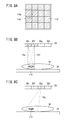
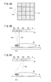
- FIG. 7A is a schematic explanatory diagram illustrating an example of determining the first and second radiation source groups when imaging the region of interest existing at the first position.
- FIG. 7B is a schematic explanatory diagram illustrating a state in which radiation is output toward the region of interest existing at the first position when the imaging mode is the still image mode.
- FIG. 7C is a schematic explanatory diagram illustrating a state in which radiation is output toward the region of interest existing at the first position when the imaging mode is the moving image mode.
- FIG. 8A is a schematic explanatory diagram illustrating an example of determining the first and second radiation source groups when imaging the region of interest existing at the second position.
- FIG. 8B is a schematic explanatory diagram illustrating a state in which radiation is output toward the region of interest existing at the second position when the imaging mode is the still image mode.
- FIG. 8C is a schematic explanatory diagram illustrating a state in which radiation is output toward the region of interest existing at the second position when the imaging mode is the moving image mode.
- FIG. 9A is a schematic explanatory diagram illustrating an example of determining the first and second radiation source groups when imaging the region of interest existing at the third position.
- FIG. 9B is a schematic explanatory diagram illustrating a state in which radiation is output toward the region of interest existing at the third position when the imaging mode is the still image mode.
- FIG. 9C is a schematic explanatory diagram illustrating a state in which radiation is output toward the region of interest existing at the third position when the imaging mode is the moving image mode.
- FIG. 9A is a schematic explanatory diagram illustrating an example of determining the first and second radiation source groups when imaging the region of interest existing at the third position.
- FIG. 9B is a schematic explanatory diagram illustrating a state in which radiation is output toward the region of interest existing at the third position when the imaging mode is the still image mode.
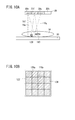
- FIG. 10A is a schematic explanatory diagram illustrating a state in which radiation is output toward a plurality of regions of interest when the imaging mode is a still image mode.
- FIG. 10B is a schematic explanatory diagram illustrating an example of determining the first and second radiation source groups when imaging a plurality of regions of interest. It is a typical top view showing the example of arrangement of each radiation source in the radiation output part concerning the 1st modification. It is an electrical block diagram of the radiation imaging system which concerns on a 2nd modification.
- the radiation imaging system 10 includes a radiation output device 18 that irradiates radiation 16 to a patient who is a subject 14 lying on an imaging table 12 such as a bed, and radiation 16 transmitted through the subject 14.
- the electronic cassette 20 which detects and converts into a radiographic image
- the console 22 which controls the radiation output device 18 and the electronic cassette 20, and the display apparatus 24 which displays a radiographic image are provided.
- the radiation output device 18, the electronic cassette 20, and the display device 24, for example, UWB (Ultra Wide Band), IEEE 802.11.
- signals are transmitted and received by wireless LAN (Local Area Network) such as a / b / g / n, or wireless communication using millimeter waves or the like. It goes without saying that signals may be transmitted and received by wired communication using a cable.
- wireless LAN Local Area Network
- the console 22 is connected to a radiology information system (RIS) 26 that centrally manages radiographic images and other information handled in the radiology department in the hospital.
- RIS radiology information system
- the RIS 26 is used to comprehensively manage medical information in the hospital.
- a medical information system (HIS) 28 to be managed is connected.
- the radiation output device 18 includes a plurality of radiation sources 30a to 30p (this notation means 30a to 30p in alphabetical order, and the same applies hereinafter).
- This is a multi-ray source type radiation output device having a unit 29.
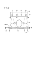
- FIG. 2 shows, as an example, a state in which four radiation sources 30a to 30d are arranged as viewed from the side surface perpendicular to the output direction of each radiation 16a to 16p.
- the letter “a” or the like attached to the reference numeral 30 (16) may be omitted.
- Each radiation source 30 is a field electron emission type radiation source or a thermal electron emission type radiation source. That is, each radiation source 30 irradiates the target with an electron beam from an electron beam generation unit (not shown), and outputs radiation 16 generated from the electron beam irradiation point (focus) on the target to the subject 14 side. Is possible.
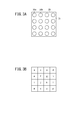
- FIG. 3A is a schematic plan view illustrating an arrangement example of each radiation source 30 provided in the radiation output device 18 illustrated in FIG.
- the radiation sources 30a to 30p are arranged in a matrix of 4 rows and 4 columns along a predetermined output surface 31 (a plane in this example).
- the arrangement positions of the radiation sources 30 may be schematically represented as square cells.
- the alphabetic character described in each cell corresponds to the subscript which distinguishes each radiation source 30 (or radiation 16).
- the electronic cassette 20 is a flexible, thin and portable radiation imaging apparatus disposed between the imaging table 12 and the subject 14.
- a thin-walled housing 32 made of a resin or metal that can transmit the radiation 16 includes a radiation conversion panel 34 that converts the radiation 16 transmitted through the housing 32 into a radiation image, and a flexible printed circuit board (
- a cassette control unit 38 for controlling the radiation conversion panel 34 through the FPC 36a and reading out an electrical signal corresponding to the radiation image from the radiation conversion panel 34 through the other FPC 36b is housed.
- the radiation conversion panel 34 includes a scintillator 42 that temporarily converts the radiation 16 into electromagnetic waves having other wavelengths such as visible light, and a plurality of solid-state detection elements (hereinafter referred to as “amorphous silicon”). It is also an indirect conversion type radiation detector composed of a photoelectric conversion layer 40 that converts it into an electrical signal using a pixel).
- a scintillator 42 including a photoelectric conversion layer 40 along the irradiation direction (output direction, incident direction) of radiation 16 and a columnar crystal 44 of cesium iodide (CsI) formed along the irradiation direction;
- the radiation conversion panel 34 of the ISS (IrradiationradiSide Sampling) system as a surface reading system in which are arranged in order is illustrated.
- the radiation 16 passes through the photoelectric conversion layer 40 and reaches the scintillator 42. Therefore, absorption of the radiation 16 in the photoelectric conversion layer 40 must be avoided as much as possible.
- the photoelectric conversion layer 40 is formed, for example, by sequentially laminating an insulating substrate, a TFT (thin film transistor) portion, and a photoelectric conversion portion (not shown) along the irradiation direction of the radiation 16.
- the photoelectric conversion unit formed on the scintillator 42 side absorbs electromagnetic waves (for example, visible light) emitted from the scintillator 42 and generates charges corresponding to the absorbed visible light.
- the photoelectric conversion unit preferably includes a photoelectric conversion film such as a-Si that absorbs visible light and generates electric charge, or an organic photoelectric conversion material (OPC).
- the TFT portion that reads out the electric charges generated in the photoelectric conversion portion preferably includes an active layer made of a-Si, amorphous oxide, organic semiconductor material, carbon nanotube, or the like.
- the insulating substrate disposed on the subject 14 side is preferably made of flexible synthetic resin, aramid, or bionanofiber. By using these materials, the flexible photoelectric conversion layer 40 can be formed by a low-temperature process, and absorption of the radiation 16 in the photoelectric conversion layer 40 can be suppressed.
- the scintillator 42 is formed by forming a columnar crystal 44 of CsI along the incident direction of the radiation 16 on a vapor deposition substrate (not shown) disposed on the bottom side of the housing 32.
- a columnar crystal 44 of cesium iodide (CsI: Tl) to which thallium is added is formed and quinacridone as OPC is used for the photoelectric conversion film described above
- the emission peak wavelength in the scintillator 42 and the photoelectric conversion Since the difference from the light absorption peak wavelength in the film can be within 5 nm, the amount of charge generated in the photoelectric conversion film can be maximized.
- a thin aluminum (Al) substrate with high heat resistance and low cost may be used as the evaporation substrate.
- the material of the scintillator 42 is not limited to CsI or CsI: Tl.
- CsI Na (sodium activated cesium iodide), GOS (gadolinium oxide sulfide, Gd 2 O 2 S: Tb), etc. Of course, these materials may be used.
- a radiation conversion panel of a back side reading method PSS method, PSS: Penetration Side Sampling
- PSS method, PSS: Penetration Side Sampling in which the scintillator 42 and the photoelectric conversion layer 40 are sequentially arranged along the irradiation direction of the radiation 16 may be used. .
- a direct conversion type radiation detector that directly converts the radiation 16 into an electric signal by a plurality of pixels made of a substance such as amorphous selenium (a-Se) may be used as the radiation conversion panel 34.
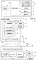
- FIG. 4 is a block configuration diagram of the radiation output device 18, the electronic cassette 20, and the console 22 constituting the radiation imaging system 10.
- the radiation output device 18 transmits and receives signals between the console 22 and a radiation source control unit 50 (output control means) that controls the output of the radiation 16 from each radiation source 30 in addition to the radiation output unit 29 described above.
- a communication unit 52 that performs the operation, a battery 54 that supplies power to the radiation output unit 29, the radiation source control unit 50, and the communication unit 52, and a moving mechanism 55 that can move each radiation source 30 integrally along the arrow A direction.
- the radiation source controller 50 controls the radiation sources 30 on and off, controls the dose of radiation 16, and the like, as well as the first radiation source group 112 (see FIG. 7A) used in the still image mode from among the plurality of radiation sources 30. ) And / or the second radiation source group 114 (see FIG. 7) to be used in the moving image mode, the region of interest 110 (see FIG. 7B, etc.) of the subject 14 to be imaged, and the radiation output unit 29 Functions as a position information acquisition unit 58 that acquires position information such as, and a radiation source selection unit 60 that selects at least one radiation source 30 used for imaging from a plurality of radiation sources 30. Further, the radiation source control unit 50 can supply a signal corresponding to the amount of movement of the radiation output unit 29 in the direction of arrow A to the moving mechanism 55 side.
- the electronic cassette 20 supplies power to the communication unit 62 that transmits and receives signals to and from the console 22, the photoelectric conversion layer 40, the cassette control unit 38, and the communication unit 62.
- a battery 64 for supplying The cassette control unit 38 reads an address signal for reading out a radiation image to the photoelectric conversion layer 40 via the FPC 36a (see FIG. 2), and reads from the photoelectric conversion layer 40 via the FPC 36b. It has an image memory 68 for storing the emitted radiographic image and a cassette ID memory 70 for storing cassette ID information for specifying the electronic cassette 20.
- the console 22 includes a communication unit 72 that transmits and receives signals to and from the communication units 52 and 62, a control processing unit 74 that executes predetermined control processing, and order information for requesting radiographic imaging of the subject 14.
- An order information storage unit 75 for storing, an imaging condition storage unit 76 for storing imaging conditions for irradiating the subject 14 with each radiation 16, an operation unit 77 such as a keyboard and a mouse, and an output of each radiation 16 from the radiation output unit 29.
- the exposure switch 78 for instructing the start timing of the medical device (hereinafter collectively referred to as an operator) and the radiation image received by the communication unit 72 from the communication unit 62 or image processing by the control processing unit 74
- the image memory 79 which memorize
- the order information is created by a doctor in the RIS 26 or HIS 28 (see FIG. 1), and in addition to subject information for specifying the subject 14 such as the name, age, and sex of the subject 14, radiation Information on the radiation output device 18 and the electronic cassette 20 used for photographing an image, a photographing part of the subject 14, and the like are included.
- the imaging conditions are various conditions necessary for irradiating each radiation 16 to the imaging region of the subject 14, such as the tube voltage and tube current of each radiation source 30, the irradiation time of each radiation 16, and the like. .
- FIG. 5 is a circuit configuration diagram of the electronic cassette 20.
- the photoelectric conversion layer 40 described above includes a plurality of pixels 80 made of a material such as a-Si that converts electromagnetic waves (visible light) converted from the radiations 16 in the scintillator 42 into electric signals. It has the structure arranged above. In this case, in each pixel 80 to which the bias voltage Vb is supplied from the battery 64 (see FIG. 4), electric charges generated by converting electromagnetic waves into electrical signals (analog signals) are accumulated, and the TFTs 86 are sequentially turned on for each row. Thus, the charge can be read out as an image signal.
- a gate line 82 extending in parallel with the row direction and a signal line 84 extending in parallel with the column direction are connected to the TFT 86 connected to each pixel 80.
- Each gate line 82 is connected to the line scan driver 90, and each signal line 84 is connected to the multiplexer 92.
- Control signals Von and Voff for controlling on / off of the TFTs 86 arranged in the row direction are supplied from the line scan driving unit 90 to the gate line 82.
- the line scan driving unit 90 includes a plurality of switches SW1 for switching the gate lines 82, and an address decoder 94 for outputting a selection signal for selecting one of the switches SW1.
- An address signal is supplied to the address decoder 94 from the address signal generator 66 (see FIG. 4) of the cassette controller 38.
- a multiplexer 92 is connected to the amplifier 96 via a sample and hold circuit 98.
- the multiplexer 92 includes a plurality of switches SW2 for switching the signal lines 84 and an address decoder 100 that outputs a selection signal for selecting one of the switches SW2.
- An address signal is supplied from the address signal generator 66 to the address decoder 100.
- An A / D converter 102 is connected to the multiplexer 92, and a radiation image converted into a digital signal by the A / D converter 102 is supplied to the cassette control unit 38.
- the TFT 86 functioning as a switching element may be realized in combination with another imaging element such as a CMOS (Complementary Metal-Oxide Semiconductor) image sensor. Further, it may be replaced with a CCD (Charge-Coupled Device) image sensor that transfers charges while shifting them by a shift pulse corresponding to the gate signal referred to in the TFT 86.
- CMOS Complementary Metal-Oxide Semiconductor
- CCD Charge-Coupled Device
- an imaging mode in which a radiographic image is acquired by a single imaging is referred to as a “still image mode”
- an imaging mode in which radiographic images are sequentially acquired by continuous imaging is referred to as a “movie mode”.
- the output of the radiation 16 and the acquisition of the radiation image are sequentially repeated at a relatively short time interval (predetermined frame rate).
- various known moving image capturing techniques such as binning can be applied in addition to the progressive method and the interlace method.
- step S1 the control processing unit 74 of the console 22 performs imaging conditions (tube voltage, tube current, irradiation time) for irradiating each radiation 16 to the imaging region of the subject 14 from each radiation source 30 based on the order information.
- This order information is, for example, information acquired from the RIS 26 (or HIS 28) and temporarily stored in the order information storage unit 75.
- control processing unit 74 stores the set imaging conditions in the imaging condition storage unit 76, and transmits the imaging conditions to the radiation output device 18 side via the communication unit 72 and the communication unit 52.
- control processing unit 74 transmits the set imaging condition or order information to the electronic cassette 20 side wirelessly via the communication unit 72 and the communication unit 62.
- the cassette control unit 38 stores the imaging conditions received via the communication unit 62 in the image memory 68 and / or the cassette ID memory 70.
- step S2 the position information acquisition unit 58 of the radiation output device 18 acquires the position information of the radiation output unit 29 and the region of interest 110 (see FIG. 7B and the like).
- the position of the radiation output unit 29 may be a predetermined reference position (for example, the center position of the output surface 31), or may be the absolute position of each of the radiation sources 30a to 30p.
- the position of the region of interest 110 may be an absolute position measured by some means, or may be a position estimated from order information such as the position / posture of the subject 14 and the imaging region.
- step S ⁇ b> 3 the group determination unit 56 of the radiation output apparatus 18 selects the first radiation source group 112 that is used in the still image mode and the second radiation source group 114 that is used in the moving image mode from among the plurality of radiation sources 30. Respectively.
- the radiation sources 30 belonging to the first radiation source group 112 are hatched cells, that is, four radiation sources 30f, 30g, 30j, and 30k existing on the center side.
- the radiation sources 30 belonging to the second radiation source group 114 are cells with halftone dots, that is, the remaining 12 radiation sources 30a to 30d, 30e, 30h, 30i, 30l, and 30m to 30p. Details of this determination method will be described later.
- step S4 upon the start of imaging of the subject 14, the radiation source control unit 50 of the radiation output apparatus 18 determines whether the imaging mode is the still image mode or the moving image mode.
- the control processing unit 74 captures the subject 14 by synchronizing the start of the output of the radiation 16 from the radiation output unit 29 with the detection of the radiation 16 in the radiation conversion panel 34 and the conversion to the radiation image.
- a synchronization control signal for executing radiographic image capturing for the region is generated.
- the control processing unit 74 transmits the generated synchronization control signal to each of the communication units 52 and 62 via the communication unit 72 by radio.
- the radiation source control unit 50 receives the synchronization control signal via the communication unit 52, imaging is started according to the imaging conditions set in advance in step S1. Thereafter, the radiation source controller 50 determines the imaging mode by referring to the order information received from the console 22 side.
- the process proceeds to step S5, and the radiation source selection unit 60 selects at least one radiation source 30 to be used for the actual imaging from the first radiation source group 112.
- the radiation source selection unit 60 has selected all the radiation sources 30 belonging to the first radiation source group 112, that is, the four radiation sources 30f, 30g, 30j, and 30k.
- the process proceeds to step S6, and the radiation source selection unit 60 selects at least one radiation source 30 to be used for the actual imaging from the second radiation source group 114. .
- the radiation source selection unit 60 selects all the radiation sources 30 belonging to the second radiation source group 114, that is, the 12 radiation sources 30a to 30d, 30e, 30h, 30i, and 30l to 30p.
- step S7 the radiation imaging system 10 images the subject 14 by outputting the radiation 16 from the radiation source 30 selected in step S5 (or S6).
- the radiation source control unit 50 irradiates the imaging region of the subject 14 with the radiation 16 having a predetermined dose from the radiation source 30 for a predetermined irradiation time according to the imaging conditions acquired from the console 22 side.
- the radiation source 30 is controlled.
- a projected image 110p of the region of interest 110 (illustrated by a two-dot chain line in FIG. 7A). Is present across the four cells (f, g, j, k) shown in FIG. 3B.
- the actual position of the region of interest 110 illustrated in FIGS. 7B and 7C is referred to as a first position.
- the radiation sources 30 f, 30 g, 30 j, and 30 k exist immediately above the first position with respect to the normal direction of the main surface of the electronic cassette 20.
- the radiation 16f and 16g are output from the two radiation sources 30f and 30g among the four radiation sources 30e to 30h belonging to the second row, respectively. Then, the radiations 16 f and 16 g are transmitted from the substantially front side of the region of interest 110 and are incident on the electronic cassette 20 substantially perpendicularly. Thereby, it is possible to obtain a high-quality radiographic image with almost no geometric distortion. Further, in order to further improve the image quality or reduce the exposure dose of the subject 14, the imaging may be performed by narrowing the irradiation fields of the radiation sources 30f and 30g as compared with the moving image mode.
- the radiations 16e and 16h are output from the two radiation sources 30e and 30h, respectively. Then, the radiations 16 e and 16 h are transmitted through the region of interest 110 from a slightly oblique direction and are incident on the electronic cassette 20. Since the moving image photographed in this way is mainly used to monitor the change in the state of the subject 14, it can sufficiently withstand its use. Further, in order to reduce the exposure dose of the subject 14, it is possible to shoot with the dose per unit time of each of the radiations 16 f and 16 g being smaller than that in the still image mode.
- the group determination part 56 determines the 1st radiation source group 112 and the 2nd radiation source group 114 so that each radiation source 30 may belong to either one of radiation source groups, it is the same subject 14 and region of interest. For 110, still and moving images can be simultaneously captured. In this case, a configuration capable of separately acquiring a still image and a moving image is required, such as providing two radiation detectors.
- the image is set in the moving image mode to perform photographing, and the operator positions the subject 14 while visually recognizing the moving image, and then performs the actual photographing. Therefore, there is a case where the mode is switched to the still image mode (and this operation is repeated).
- the radiation source 30 can be appropriately selected according to the same concept.
- a projected image 110p of the region of interest 110 (illustrated by a two-dot chain line in FIG. 8A). Is present across the four cells (e, f, i, j) shown in FIG. 3B.
- the actual position of the region of interest 110 illustrated in FIGS. 8B and 8C is referred to as a second position.
- the group determination unit 56 sorts the radiation sources 30 having a relatively short actual distance from the region of interest 110 (that is, the distance from the projected image 110p on the output surface 31) into the first radiation source group (step) (See S3).
- the radiation sources 30 belonging to the first radiation source group 116 are assumed to be four radiation sources 30e, 30f, 30i, and 30j existing on the left center side.
- the radiation sources 30 belonging to the second radiation source group 118 are the remaining 12 radiation sources 30a to 30d, 30g, 30h, 30k, 30l, and 30m to 30p.
- the radiation source selection unit 60 selects at least one radiation source 30 used for the actual imaging from the first radiation source group 116 (see step S5). For example, assume that all four radiation sources 30e, 30f, 30i, and 30j are selected. Then, as shown in FIG. 8B, among the four radiation sources 30e to 30h belonging to the second row, the radiation 16e and 16f are output from the two radiation sources 30e and 30f, respectively.
- the radiation source selection unit 60 selects at least one radiation source 30 to be used for the actual imaging from the second radiation source group 118 (see step S6). For example, among the remaining radiation sources 30a to 30d, 30g, 30h, 30k, and 30l to 30p, eight radiation sources 30a to 30c, 30g, 30k, and 30m to 30o having a relatively small irradiation angle with respect to the region of interest 110 are selected. Suppose that then, as shown in FIG. 8C, radiation 16g is output from one radiation source 30g among the four radiation sources 30e to 30h belonging to the second row.
- At least one radiation source 30 used for imaging according to the positional relationship between the region of interest 110 (second position) and each radiation source 30, either the still image mode or the moving image mode is selected. Even in this imaging mode, it is possible to perform imaging suitable for each position of the region of interest 110.
- a projected image 110p of the region of interest 110 (illustrated by a two-dot chain line in FIG. 9A). Is present to the left of the two cells (e, i) shown in FIG. 3B.
- the actual position of the region of interest 110 illustrated in FIGS. 9B and 9C is referred to as a third position.
- the radiation source control unit 50 moves the radiation output unit 29 to the left by a predetermined amount (for example, 1.5 cells) along the arrow A direction via the moving mechanism 55. Then, the positional relationship between the radiation output unit 29 and the region of interest 110 is the same as that shown in FIGS. 8B and 8C. Thereafter, the radiation source 30 can be selected in the same manner as when the region of interest 110 is present at the second position.
- a predetermined amount for example, 1.5 cells
- a plurality of regions of interest specifically, the region of interest 110 existing at the first position and another region of interest 120 exist in the subject 14.
- a projected image 120p of the region of interest 120 is shown in FIG. 3B.
- the actual position of the region of interest 120 illustrated in FIG. 10B is referred to as a fourth position.
- the group determination unit 56 has an actual distance (that is, a distance from the projected images 110p and 120p on the output surface 31) to either the region of interest 110 (first position) or the region of interest 120 (fourth position).
- the relatively short radiation sources 30 are sorted into first radiation source groups (see step S3).
- the radiation sources 30 belonging to the first radiation source group 122 are the seven radiation sources 30a, 30b, 30e to 30g, 30j, and 30k existing on the upper left side.
- the radiation sources 30 belonging to the second radiation source group 124 are the remaining nine radiation sources 30c, 30d, 30h, 30i, and 30l to 30p.
- the radiations 16e to 16g are output from the three radiation sources 30e to 30g, respectively.
- the radiation source control unit 50 selects two or more radiation sources 30, the radiation sources 30 arranged in a cluster in a plan view of the output surface 31. May be selected.
- the cluster form means that any one radiation source 30 belonging to the cluster is in a positional relationship adjacent to at least one other radiation source 30.
- the radiation source control unit 50 may switch the radiation source 30 to be used at a predetermined time interval when the imaging mode is the moving image mode.
- the radiation source control unit 50 controls the radiation sources 30a, 30c, 30e, 30h, 30i,... In the second radiation source group 114 shown in FIG. In this way, by selecting the radiation source 30c existing at a position not adjacent to the radiation source 30a used most recently and / or using each radiation source 30 at substantially the same frequency, Heat generated from the target can be efficiently released and heat can be effectively avoided from being trapped in the radiation output device 18.
- the radiation imaging system 10 captures the subject 14 by outputting the radiation 16 from the radiation source 30 appropriately selected according to the imaging mode (step S7).
- the radiation output device 18 may automatically change the radiation source 30 used for imaging in response to an instruction to change various imaging conditions such as an imaging mode and a region of interest.
- the radiation source 30 used for imaging may be configured to be changeable by accepting a manual operation by an operator.
- step S8 the radiation imaging system 10 acquires a radiation image of the subject 14.
- the operation of each unit will be described in detail.
- the radiation 16 transmitted through the subject 14 (imaging site) reaches the radiation conversion panel 34 in the electronic cassette 20.
- the scintillator 42 which consists of the columnar crystal 44 of CsI or CsI: Tl emits visible light of the intensity
- Each pixel 80 which comprises the photoelectric converting layer 40 uses visible light as an electrical signal. Convert and accumulate as charge.
- step S4 since the synchronization control signal is transmitted from the control processing unit 74 to the communication unit 62 via the communication unit 72, the cassette control unit 38 receives the synchronization control signal via the communication unit 62, By supplying an address signal from the address signal generator 66 to the line scan driver 90 and the multiplexer 92, the charge information which is a radiographic image of the subject 14 held in each pixel 80 is read out.
- the address decoder 94 of the line scan driver 90 outputs a selection signal according to the address signal supplied from the address signal generator 66 to select one of the switches SW1, and the TFT 86 connected to the corresponding gate line 82.
- a control signal Von is supplied to the gates of the two.
- the address decoder 100 of the multiplexer 92 outputs a selection signal in accordance with the address signal supplied from the address signal generation unit 66, sequentially switches the switch SW2, and is connected to the gate line 82 selected by the line scan driving unit 90. Radiation images as charge information held in each pixel 80 are sequentially read out via the signal line 84.
- the radiation image read out from each pixel 80 connected to the selected gate line 82 is amplified by each amplifier 96, sampled by each sample hold circuit 98, and then A / D converter via the multiplexer 92. 102, and converted into a digital signal.
- the radiographic image converted into the digital signal is temporarily stored in the image memory 68 of the cassette control unit 38.
- the address decoder 94 of the line scan driving unit 90 sequentially switches the switch SW1 according to the address signal supplied from the address signal generating unit 66, and the charge held in each pixel 80 connected to each gate line 82.
- a radiographic image as information is read out via the signal line 84 and stored in the image memory 68 of the cassette control unit 38 via the multiplexer 92 and the A / D converter 102.
- the cassette control unit 38 acquires a radiation image from the charges held in each pixel 80 at a preset frame rate (for example, 15 to 60 frames / second). For example, by reading each charge using an interlace method, it is possible to improve the frame rate and reduce the burden on the signal processing system.
- step S9 the display device 24 receives the radiation image acquired by the electronic cassette 20 via the console 22 and displays it as an interpretation image.
- the cassette control unit 38 receives the radiographic image stored in the image memory 68 and the cassette ID information stored in the cassette ID memory 70 in response to a transmission request from the console 22 received via the communication unit 62. And wirelessly transmitted to the console 22 via the communication unit 62. Then, the control processing unit 74 performs predetermined image processing (for example, known image reconstruction processing) on the received radiographic image, and generates an interpretation image that can be interpreted by an operator. Then, the control processing unit 74 transmits the interpretation image to the display device 24 wirelessly via the communication unit 72.
- predetermined image processing for example, known image reconstruction processing
- step S10 the operator visually recognizes the interpretation image displayed on the display device 24, and determines whether or not a desired radiation image has been obtained. If it is determined that the image has been obtained (YES), the shooting for the subject 14 is terminated. On the other hand, if it is determined that it has not been obtained (NO), the process returns to step S4 and re-shooting of the subject 14 is executed.
- At least one radiation source 30 that outputs the radiation 16 is selected from the plurality of radiation sources 30 depending on whether the imaging mode is the still image mode or the moving image mode.
- the radiation 16 can be output from a position suitable for each imaging mode without requiring the movement of the source 30 and the change of positioning. This greatly improves the operator's work efficiency when performing radiation imaging using both the still image mode and the moving image mode.
- the operator administers a contrast medium from the blood vessel (artery or vein) of the subject 14. Then, the operator takes an image in the moving image mode immediately after administration, and looks at the timing when the contrast agent reaches the specific site while visually recognizing the moving image of the specific site. In this moving image mode, radiation imaging at a wide angle (see FIGS. 7C and 8C) and a low resolution is successively performed.
- the administered contrast medium is circulated through the body of the subject 14 through the blood vessels, and reaches a specific site such as the heart after a predetermined time has elapsed.
- the radiation source control unit 50 switches from the moving image mode to the still image continuous shooting mode in accordance with the operation of the operation unit 77 by the operator.
- “still image continuous shooting” refers to a shooting mode in which shooting in the still image mode is successively performed at a time interval longer than the frame interval in the moving image mode.
- radiation imaging is performed successively with a narrow angle (see FIGS. 7B and 8B) and high resolution. That is, a diagnostic image with high contrast and resolution can be obtained by photographing a specific part in the still image mode in a time zone in which the amount of contrast agent reached is large. Further, by acquiring still images successively by continuous shooting, the timing is not lost even in the case of imaging using a contrast agent. Furthermore, the dynamics of a specific part can be easily grasped by sequentially connecting a plurality of obtained still images.
- the radiation source control unit 50 sequentially executes the output control of the radiation 16 according to the still image mode at a time interval longer than the frame interval in the moving image mode. Even if the characteristic) changes from moment to moment, shooting in the still image mode can be reliably executed without losing timing.
- the radiation output unit 130 according to the first modification is different from the present embodiment (see FIG. 3A) regarding the arrangement (number and position) of the radiation source 30.
- the output surface 132 on the output side of the radiation 16 has a circular shape.
- One radiation source 30 a is arranged at the center position of the output surface 31.
- Eight radiation sources 30b to 30i are arranged at equal intervals along the circumference of the periphery of the output surface 31.
- the size of the radiation source 30a is larger than each size of the radiation sources 30b to 30i.
- the group determining unit 56 may sort one radiation source 30a into the first radiation source group and use it only in the still image mode.
- the other radiation sources 30b to 30i may be appropriately selected according to the imaging mode (still image mode, moving image mode) and / or the positional relationship with the region of interest 110.
- the shape of the output surfaces 31 and 132 in the present embodiment is a flat shape, it may be a curved surface or other shapes. Needless to say, the number or position of the radiation sources 30 can be changed as needed.
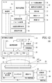
- the radiation imaging system 140 according to the second modified example is different from the present embodiment (see FIG. 4) regarding the configuration of the output control means for controlling the output of the radiation 16.
- the radiation source control unit 142 of the radiation output device 18 has only a function of executing on / off control of each radiation source 30, control of the dose of radiation 16, and the like.
- the console 22 includes a communication unit 72, a control processing unit 74, an order information storage unit 75, an imaging condition storage unit 76, an operation unit 77, an exposure switch 78 and an image memory 79, a group determination unit 56, position information
- a radiation source determination unit 144 having functions of the acquisition unit 58 and the radiation source selection unit 60 is further provided.
- the radiation source determination unit 144 selects at least one radiation source 30 used for the main imaging from the plurality of radiation sources 30a to 30p, as in the case of the present embodiment. Then, the control processing unit 74 transmits information on the selection result by the radiation source determining unit 144 (hereinafter referred to as “radiation source selection information”) to the radiation source control unit 142 via the communication unit 72 and the communication unit 52.
- the radiation source control unit 142 may control the radiation source 30 based on the received radiation source selection information and output the radiation 16.
- the output control means in the second modified example includes the radiation source control unit 142 of the radiation output device 18 and the radiation source determination unit 144 of the console 22.
- the output control means is constituted by a plurality of devices (the radiation output device 18 and the console 22), the same effects as those of the present embodiment can be obtained.
Landscapes
- Health & Medical Sciences (AREA)
- Life Sciences & Earth Sciences (AREA)
- Engineering & Computer Science (AREA)
- Medical Informatics (AREA)
- Physics & Mathematics (AREA)
- High Energy & Nuclear Physics (AREA)
- Molecular Biology (AREA)
- Nuclear Medicine, Radiotherapy & Molecular Imaging (AREA)
- Biomedical Technology (AREA)
- Veterinary Medicine (AREA)
- Public Health (AREA)
- Optics & Photonics (AREA)
- Pathology (AREA)
- Radiology & Medical Imaging (AREA)
- Biophysics (AREA)
- Heart & Thoracic Surgery (AREA)
- Surgery (AREA)
- Animal Behavior & Ethology (AREA)
- General Health & Medical Sciences (AREA)
- General Physics & Mathematics (AREA)
- Spectroscopy & Molecular Physics (AREA)
- Apparatus For Radiation Diagnosis (AREA)
Abstract
本発明は、放射線撮影システム及び放射線撮影方法に関する。放射線出力装置(18)は、所定面(31、132)に沿って配置された複数の放射線源(30、30a~30p)を有する。そして、撮影形態が静止画モードであるか動画モードであるかに応じて、複数の放射線源(30、30a~30p)のうち放射線(16、16a~16p)を出力する放射線源(30、30a~30p)を少なくとも1つ選択する。
Description
この発明は、所定面に沿って配置された複数の放射線源を有する放射線出力装置を用いた放射線撮影システム及び放射線撮影方法に関する。
近時、所定面に沿って配置された複数の放射線源を収容した放射線出力装置、及びこの装置を用いた放射線撮影方法が種々提案されている。
特開2010-115270号公報には、透視撮影(動画撮影)の際、コリメータの大きさ及び位置を制御することで、観察面積の拡縮等の変更が好適に実行できる旨が記載されている。
ところで、放射線撮影は、時間的要素の有無によって2つの撮影形態、具体的には、一回的な撮影により放射線画像を取得する静止画モードと、連続的な撮影により放射線画像を順次取得する動画モードとに大別される。しかし、特開2010-115270号公報には、静止画モード及び動画モードを併用する放射線撮影を行う場合に関する具体的提案が何らされておらず、複数の放射線源をどのように使用すればよいかが問題となる。
本発明は上記した問題を解決するためになされたもので、静止画モード及び動画モードを併用する放射線撮影を行う際の、オペレータの作業効率を大幅に向上可能な放射線撮影システム及び放射線撮影方法を提供することを目的とする。
本発明に係る放射線撮影システムは、所定面に沿って配置された複数の放射線源を有する放射線出力装置と、前記放射線出力装置の各前記放射線源からの放射線の出力を制御する出力制御手段とを備え、前記出力制御手段は、撮影形態が静止画モードであるか動画モードであるかに応じて、前記複数の放射線源のうち前記放射線を出力する放射線源を少なくとも1つ選択する線源選択部を備えることを特徴とする。
このように、出力制御手段は、撮影形態が静止画モードであるか動画モードであるかに応じて、複数の放射線源のうち放射線を出力する放射線源を少なくとも1つ選択するようにしたので、放射線源の移動、ポジショニングの変更等を必要とせずに、各撮影形態に適した位置からの放射線の出力が可能になる。これにより、静止画モード及び動画モードを併用する放射線撮影を行う際の、オペレータの作業効率が大幅に向上する。
また、前記所定面は平面であり、前記複数の放射線源はマトリクス状に配置されていることが好ましい。
さらに、前記出力制御手段は、前記複数の放射線源の中から前記静止画モードに供される第1線源グループを決定するグループ決定部をさらに備え、前記線源選択部は、撮影形態が前記静止画モードである場合、前記グループ決定部により決定された前記第1線源グループの中から前記放射線源を少なくとも1つ選択することが好ましい。これにより、静止画モードでの放射線撮影に適した少なくとも1つの位置からの放射線の出力が可能である。
さらに、前記グループ決定部は、前記複数の放射線源の中から前記動画モードに供される第2線源グループをさらに決定し、前記線源選択部は、撮影形態が前記動画モードである場合、前記グループ決定部により決定された前記第2線源グループの中から前記放射線源を少なくとも1つ選択することが好ましい。これにより、動画モードでの放射線撮影に適した少なくとも1つの位置からの放射線の出力が可能である。
さらに、前記グループ決定部は、各前記放射線源がいずれか一方の線源グループに属するように、前記第1線源グループ及び前記第2線源グループを決定することが好ましい。
また、前記線源選択部は、さらに、撮影対象である被写体の関心領域と各前記放射線源との間の位置関係に応じて前記放射線源を少なくとも1つ選択することが好ましい。これにより、静止画モード、動画モードのいずれの撮影形態であっても、関心領域に適した放射線撮影を行うことができる。
さらに、撮影形態が前記静止画モードである場合、前記線源選択部は、前記関心領域と各前記放射線源との距離が短い位置に存在する前記放射線源を少なくとも1つ選択することが好ましい。
さらに、撮影形態が前記静止画モードである場合、前記線源選択部は、前記関心領域に対する前記放射線の照射角度が小さい位置に存在する前記放射線源を少なくとも1つ選択することが好ましい。
さらに、前記線源選択部は、前記所定面の平面視で、クラスタ状に配置された2以上の放射線源を選択することが好ましい。これにより、一時に出力される各放射線を密に結束可能であり、放射線画像中に幾何学的歪みが発生することを抑制できる。
さらに、前記出力制御手段は、前記動画モードにおけるフレーム間隔よりも長い時間間隔で、前記静止画モードに応じた前記放射線の出力の制御を遂次実行することが好ましい。これにより、撮影対象の状態(放射線画像の特性)が時々刻々と変化する場合であっても、タイミングを逸することなく静止画モードでの撮影を確実に実行できる。
さらに、前記複数の放射線源を一体的に移動させる移動機構をさらに備えることが好ましい。
さらに、前記複数の放射線源から出力された各前記放射線を放射線画像に変換する放射線撮影装置をさらに備えることが好ましい。
本発明に係る放射線撮影方法は、所定面に沿って配置された複数の放射線源を有する放射線出力装置を用いた方法であって、撮影形態が静止画モードであるか動画モードであるかに応じて、前記放射線出力装置の前記複数の放射線源のうち放射線を出力する放射線源を少なくとも1つ選択するステップを備えることを特徴とする。
本発明に係る放射線撮影システム及び放射線撮影方法によれば、撮影形態が静止画モードであるか動画モードであるかに応じて、複数の放射線源のうち放射線を出力する放射線源を少なくとも1つ選択するようにしたので、放射線源の移動、ポジショニングの変更等を必要とせずに、各撮影形態に適した位置からの放射線の出力が可能になる。これにより、静止画モード及び動画モードを併用する放射線撮影を行う際の、オペレータの作業効率が大幅に向上する。
以下、本発明に係る放射線撮影方法について放射線撮影システムとの関係において好適な実施形態を挙げ、添付の図面を参照して説明する。
[放射線撮影システム10の構成]
図1に示すように、放射線撮影システム10は、ベッド等の撮影台12に横臥した被写体14である患者に対して、放射線16を照射する放射線出力装置18と、被写体14を透過した放射線16を検出して放射線画像に変換する電子カセッテ20と、放射線出力装置18及び電子カセッテ20を制御するコンソール22と、放射線画像を表示する表示装置24とを備える。
図1に示すように、放射線撮影システム10は、ベッド等の撮影台12に横臥した被写体14である患者に対して、放射線16を照射する放射線出力装置18と、被写体14を透過した放射線16を検出して放射線画像に変換する電子カセッテ20と、放射線出力装置18及び電子カセッテ20を制御するコンソール22と、放射線画像を表示する表示装置24とを備える。
コンソール22と放射線出力装置18、電子カセッテ20及び表示装置24との間では、例えば、UWB(Ultra Wide Band)、IEEE802.11.a/b/g/n等の無線LAN(Local Area Network)、又は、ミリ波等を用いた無線通信により信号の送受信が行われる。なお、ケーブルを用いた有線通信により信号の送受信を行ってもよいことは勿論である。
コンソール22には、病院内の放射線科において取り扱われる放射線画像やその他の情報を統括的に管理する放射線科情報システム(RIS)26が接続され、RIS26には、病院内の医事情報を統括的に管理する医事情報システム(HIS)28が接続されている。
図2及び図3Aに示すように、放射線出力装置18は、複数の放射線源30a~30p(この表記は、アルファベット順に30aから30pまでを意味し、以下同様とする。)から構成される放射線出力部29を有するマルチ線源方式の放射線出力装置である。なお、図2では、一例として、各放射線16a~16pの出力方向に垂直する側面から視て、4個の放射線源30a~30dが配置された状態を示している。以下、個々の放射線源あるいは個々の放射線を区別することなく共通的に説明する場合には、参照符号30(16)に付するアルファベット文字「a」等を省略する場合がある。
各放射線源30は、電界電子放出型の放射線源、又は、熱電子放出型の放射線源である。すなわち、各放射線源30は、図示しない電子ビーム発生部からターゲットに電子ビームを照射することにより、該ターゲットにおける電子ビームの照射箇所(焦点)から発生する放射線16を被写体14側にそれぞれ出力することが可能である。
図3Aは、図2に示す放射線出力装置18が備える各放射線源30の配置例を図示した模式的平面図である。放射線源30a~30pは、所定の出力面31(本図例では、平面)に沿って4行4列のマトリクス状に配置されている。説明の便宜のため、以下の図面(例えば、図7A等)において、図3Bに示すように、各放射線源30の配置位置を正方状のセルとして模式的に表記する場合がある。なお、各セルに表記されたアルファベット文字は、放射線源30(あるいは放射線16)を各々区別する添字に該当する。
図2に戻って、電子カセッテ20は、撮影台12と被写体14との間に配置される可撓性を有する薄型且つ可搬型の放射線撮影装置である。電子カセッテ20において、放射線16を透過可能な樹脂又は金属からなる薄肉の筐体32内には、該筐体32を透過した放射線16を放射線画像に変換する放射線変換パネル34と、フレキシブルプリント基板(FPC)36aを介して放射線変換パネル34を制御する一方で、他のFPC36bを介して放射線変換パネル34から放射線画像に応じた電気信号を読み出すカセッテ制御部38とが収容されている。
放射線変換パネル34は、放射線16を可視光等の他の波長の電磁波に一旦変換するシンチレータ42と、変換した電磁波をアモルファスシリコン(a-Si)等の物質からなる複数の固体検出素子(以下、画素ともいう。)を用いて電気信号に変換する光電変換層40とから構成される間接変換型の放射線検出器である。
本図では、放射線16の照射方向(出力方向、入射方向)に沿って、光電変換層40と、前記照射方向に沿って形成されたヨウ化セシウム(CsI)の柱状結晶44を含むシンチレータ42とが順に配置された表面読取方式としてのISS(Irradiation Side Sampling)方式の放射線変換パネル34を図示している。このISS方式の放射線変換パネル34では、放射線16は、光電変換層40を透過してシンチレータ42に至るので、光電変換層40における放射線16の吸収は、極力回避しなければならない。
そこで、光電変換層40は、放射線16の照射方向に沿って、例えば、図示しない絶縁性基板、TFT(薄膜トランジスタ)部及び光電変換部を順に積層することにより形成される。シンチレータ42側に形成される光電変換部は、該シンチレータ42から放出された電磁波(例えば、可視光)を吸収し、吸収した可視光に応じた電荷を発生する。具体的に、光電変換部は、例えば、可視光を吸収して電荷を発生するa-Siや有機光電変換材料(OPC)等の光電変換膜を含み構成されることが好ましい。光電変換部で発生した電荷を読み出すTFT部は、a-Si、非晶質酸化物、有機半導体材料、カーボンナノチューブ等からなる活性層を含み構成されることが好ましい。被写体14側に配置される絶縁性基板は、可撓性を有する合成樹脂、アラミド又はバイオナノファイバからなることが好ましい。これらの材料を用いることにより、低温プロセスで可撓性を有する光電変換層40を形成することが可能になると共に、光電変換層40における放射線16の吸収を抑制することができる。
一方、シンチレータ42は、筐体32の底面側に配置された図示しない蒸着基板上に放射線16の入射方向に沿ってCsIの柱状結晶44を形成することにより構成される。この場合、タリウムが添加されたヨウ化セシウム(CsI:Tl)の柱状結晶44を形成すると共に、前述した光電変換膜にOPCとしてのキナクリドンを用いれば、シンチレータ42での発光ピーク波長と、光電変換膜での光吸収ピーク波長との差を5nm以内にすることが可能であるため、光電変換膜で発生する電荷量を最大化することができる。なお、蒸着基板としては、耐熱性が高く、且つ、低コストの薄厚のアルミニウム(Al)基板を用いればよい。
なお、シンチレータ42の材料としては、CsI又はCsI:Tlに限定されることはなく、CsI:Na(ナトリウム賦活ヨウ化セシウム)、GOS(ガドリニウム・オキサイド・サルファ、Gd2O2S:Tb)等の材料を用いてもよいことは勿論である。また、本実施形態では、放射線16の照射方向に沿って、シンチレータ42及び光電変換層40が順に配置された裏面読取方式(PSS方式、PSS:Penetration Side Sampling)の放射線変換パネルを用いてもよい。さらに、本実施形態では、放射線変換パネル34として、放射線16をアモルファスセレン(a-Se)等の物質からなる複数の画素により電気信号に直接変換する直接変換型の放射線検出器を用いてもよい。
図4は、放射線撮影システム10を構成する放射線出力装置18、電子カセッテ20及びコンソール22のブロック構成図である。
放射線出力装置18は、前述した放射線出力部29に加え、各放射線源30からの放射線16の出力を制御する線源制御部50(出力制御手段)と、コンソール22との間で信号の送受信を行う通信部52と、放射線出力部29、線源制御部50及び通信部52に電力を供給するバッテリ54と、各放射線源30を矢印A方向に沿って一体的に移動可能な移動機構55とを有する。
線源制御部50は、各放射線源30のオンオフ制御、放射線16の線量等の制御の他、複数の放射線源30の中から静止画モードに供される第1線源グループ112(図7A参照)及び/又は動画モードに供される第2線源グループ114(同図参照)を決定するグループ決定部56、撮影対象である被写体14の関心領域110(図7B等参照)や放射線出力部29等の位置情報を取得する位置情報取得部58、及び複数の放射線源30の中から撮影に使用される放射線源30を少なくとも1つ選択する線源選択部60として機能する。また、線源制御部50は、放射線出力部29の矢印A方向の移動量に応じた信号を移動機構55側に供給可能である。
電子カセッテ20は、前述した放射線変換パネル34及びカセッテ制御部38に加え、コンソール22との間で信号の送受信を行う通信部62と、光電変換層40、カセッテ制御部38及び通信部62に電力を供給するバッテリ64とを有する。カセッテ制御部38は、放射線画像の読出しを行うためのアドレス信号をFPC36a(図2参照)を介して光電変換層40に供給するアドレス信号発生部66と、光電変換層40からFPC36bを介して読み出された放射線画像を記憶する画像メモリ68と、電子カセッテ20を特定するためのカセッテID情報を記憶するカセッテIDメモリ70とを有する。
コンソール22は、各通信部52、62との間で信号の送受信を行う通信部72、所定の制御処理を実行する制御処理部74、被写体14に対する放射線画像の撮影を要求するためのオーダ情報を記憶するオーダ情報記憶部75、被写体14に各放射線16を照射させるための撮影条件を記憶する撮影条件記憶部76、キーボードやマウス等の操作部77、放射線出力部29からの各放射線16の出力の開始タイミングを医師又は技師(以下、総称してオペレータという。)が指示するための曝射スイッチ78、及び、通信部72が通信部62から受信した放射線画像や、制御処理部74で画像処理が施された放射線画像を記憶する画像メモリ79を有する。
なお、オーダ情報とは、RIS26又はHIS28(図1参照)において、医師により作成されるものであり、被写体14の氏名、年齢、性別等、被写体14を特定するための被写体情報に加えて、放射線画像の撮影に使用する放射線出力装置18及び電子カセッテ20の情報や、被写体14の撮影部位等が含まれる。また、撮影条件とは、例えば、各放射線源30の管電圧や管電流、各放射線16の照射時間等、被写体14の撮影部位に対して各放射線16を照射させるために必要な各種条件である。
図5は、電子カセッテ20の回路構成図である。
前述した光電変換層40は、シンチレータ42において各放射線16から変換された電磁波(可視光)を電気信号に変換するa-Si等の物質からなる複数の画素80を、行列状のTFT86のアレイの上に配置した構造を有する。この場合、バッテリ64(図4参照)からバイアス電圧Vbが供給される各画素80では、電磁波を電気信号(アナログ信号)に変換することにより発生した電荷が蓄積され、各行毎にTFT86を順次オンにすることにより前記電荷を画像信号として読み出すことができる。
各画素80に接続されるTFT86には、行方向と平行に延びるゲート線82と、列方向と平行に延びる信号線84とが接続される。各ゲート線82は、ライン走査駆動部90に接続され、各信号線84は、マルチプレクサ92に接続される。ゲート線82には、行方向に配列されたTFT86をオンオフ制御する制御信号Von、Voffがライン走査駆動部90から供給される。この場合、ライン走査駆動部90は、ゲート線82を切り替える複数のスイッチSW1と、スイッチSW1の1つを選択する選択信号を出力するアドレスデコーダ94とを備える。アドレスデコーダ94には、カセッテ制御部38のアドレス信号発生部66(図4参照)からアドレス信号が供給される。
また、信号線84には、列方向に配列されたTFT86を介して各画素80に保持されている電荷が流出する。この電荷は、増幅器96によって増幅される。増幅器96には、サンプルホールド回路98を介してマルチプレクサ92が接続される。マルチプレクサ92は、信号線84を切り替える複数のスイッチSW2と、スイッチSW2の1つを選択する選択信号を出力するアドレスデコーダ100とを備える。アドレスデコーダ100には、アドレス信号発生部66からアドレス信号が供給される。マルチプレクサ92には、A/D変換器102が接続され、A/D変換器102によってデジタル信号に変換された放射線画像がカセッテ制御部38に供給される。
スイッチング素子として機能するTFT86は、CMOS(Complementary Metal-Oxide Semiconductor)イメージセンサ等、他の撮影素子と組み合わせて実現してもよい。また、TFT86で言うところのゲート信号に相当するシフトパルスにより電荷をシフトしながら転送するCCD(Charge Coupled Device)イメージセンサに置き換えてもよい。
なお、本明細書において、一回的な撮影により放射線画像を取得する撮影形態のことを「静止画モード」といい、連続的な撮影により放射線画像を順次取得する撮影形態のことを「動画モード」という。動画モードでは、比較的短い時間間隔(所定のフレームレート)で、放射線16の出力及び放射線画像の取得を順次繰り返す。なお、動画モードの場合、例えば、プログレッシブ方式、インターレース方式のほか、ビニング等の公知の動画撮影技術を種々適用できる。
[放射線撮影システム10の動作説明]
次に、本実施形態に係る放射線撮影システム10の動作について、主に図6のフローチャート及び図4のブロック図を参照しながら説明する。
次に、本実施形態に係る放射線撮影システム10の動作について、主に図6のフローチャート及び図4のブロック図を参照しながら説明する。
ステップS1において、コンソール22の制御処理部74は、オーダ情報に基づいて、各放射線源30から被写体14の撮影部位に各放射線16を照射させるための撮影条件(管電圧、管電流、照射時間)を設定する。このオーダ情報は、例えば、RIS26(又はHIS28)から取得され、オーダ情報記憶部75に一時的に記憶された情報である。
その後、制御処理部74は、設定した撮影条件を撮影条件記憶部76に記憶させると共に、通信部72、通信部52を介して、当該撮影条件を放射線出力装置18側に送信する。また、制御処理部74は、設定した撮影条件あるいはオーダ情報を、通信部72、通信部62を介して無線により電子カセッテ20側に送信する。その後、カセッテ制御部38は、通信部62を介して受信した撮影条件等を画像メモリ68及び/又はカセッテIDメモリ70に記憶する。なお、これらの送信処理は、撮影条件の設定後に即時に実行してもよいし、放射線出力装置18又は電子カセッテ20からの送信要求に応じて実行してもよい。
ステップS2において、放射線出力装置18の位置情報取得部58は、放射線出力部29及び関心領域110(図7B等参照)の位置情報を取得する。放射線出力部29の位置は、所定の基準位置(例えば、出力面31の中央位置)であってもよいし、各放射線源30a~30pの絶対位置であってもよい。関心領域110の位置は、何らかの手段により計測等された絶対位置であってもよいし、被写体14の位置・姿勢、撮影部位等のオーダ情報から推定した位置であってもよい。
ステップS3において、放射線出力装置18のグループ決定部56は、複数の放射線源30の中から、静止画モードに供される第1線源グループ112及び動画モードに供される第2線源グループ114をそれぞれ決定する。
図7Aに示すように、第1線源グループ112に属する放射線源30は、ハッチングを付したセル、すなわち中央側に存在する4つの放射線源30f、30g、30j、30kである。第2線源グループ114に属する放射線源30は、網点を付したセル、すなわち残余の12個の放射線源30a~30d、30e、30h、30i、30l、30m~30pである。この決定方法の詳細については後述する。
ステップS4において、被写体14の撮影開始を受けて、放射線出力装置18の線源制御部50は、撮影形態が静止画モードであるか動画モードであるかを判別する。
オペレータは、被写体14と撮影台12との間に電子カセッテ20(図1等参照)を挿入し、被写体14のポジショニングを行った後、曝射スイッチ78を投入する。これにより、制御処理部74は、放射線出力部29からの放射線16の出力の開始と、放射線変換パネル34における放射線16の検出及び放射線画像への変換との同期を取ることにより、被写体14の撮影部位に対する放射線画像の撮影を実行するための同期制御信号を生成する。そして、制御処理部74は、無線により通信部72を介して、生成した同期制御信号を各通信部52、62にそれぞれ送信する。そして、線源制御部50が通信部52を介して同期制御信号を受信すると、ステップS1で予め設定された撮影条件に従って撮影が開始される。その後、線源制御部50は、コンソール22側から受信したオーダ情報を参照することで撮影形態を判別する。
撮影形態が静止画モードであると判別された場合、ステップS5に進み、線源選択部60は、第1線源グループ112の中から本撮影に使用する放射線源30を少なくとも1つ選択する。ここで、線源選択部60は、第1線源グループ112に属するすべての放射線源30、すなわち、4つの放射線源30f、30g、30j、30kを選択したとする。
一方、撮影形態が動画モードであると判別された場合、ステップS6に進み、線源選択部60は、第2線源グループ114の中から本撮影に使用する放射線源30を少なくとも1つ選択する。ここで、線源選択部60は、第2線源グループ114に属するすべての放射線源30、すなわち、12個の放射線源30a~30d、30e、30h、30i、30l~30pを選択したとする。
ステップS7において、放射線撮影システム10は、ステップS5(又はS6)で選択された放射線源30から放射線16を出力することで、被写体14の撮影を行う。具体的には、線源制御部50は、コンソール22側から取得した撮影条件に応じて、放射線源30から所定の線量からなる放射線16を、被写体14の撮影部位に所定の照射時間だけ照射するように当該放射線源30を制御する。
以下、各撮影形態における好ましい撮影方法について、図7A~図10Bを参照しながら詳細に説明する。なお、説明の簡略化のため、一部の放射線源30(図3Bに示すマトリクスの第2行のみ)に注目して図示及び説明する。
第1の事例として、電子カセッテ20の法線方向に沿って、関心領域110を出力面31上に投影させた場合、関心領域110の投影像110p(図7Aにおいて二点鎖線で図示する。)が、図3Bに示す4つのセル(f,g,j,k)に跨いで存在したとする。以下、図7B及び図7Cに示す関心領域110の実位置を第1位置という。換言すれば、放射線源30f、30g、30j、30kは、電子カセッテ20の主面の法線方向に対し、第1位置の直上に存在している。
図7Bに示すように、静止画モードでの撮影の際、第2行に属する4つの放射線源30e~30hのうち、2つの放射線源30f、30gからそれぞれ放射線16f、16gが出力される。そうすると、各放射線16f、16gは、関心領域110の略正面側から透過され、電子カセッテ20に対して略垂直に入射される。これにより、幾何学的な歪みが殆ど発生しない高画質の放射線画像を得ることができる。また、更なる高画質化あるいは被写体14の被曝線量の低減を図るため、動画モードと比べて、各放射線源30f、30gの照射野を絞って撮影してもよい。
図7Cに示すように、動画モードでの撮影の際、第2行に属する4つの放射線源30e~30hのうち、2つの放射線源30e、30hからそれぞれ放射線16e、16hが出力される。そうすると、各放射線16e、16hは、関心領域110の僅かに斜め方向から透過され、電子カセッテ20に入射される。このように撮影された動画像は、被写体14の状態変化を監視するために主に用いられるので、その用途に十分に堪え得る。また、被写体14の被曝線量の低減を図るため、静止画モードと比べて、各放射線16f、16gの単位時間当りの線量を少なくして撮影してもよい。
また、グループ決定部56は、各放射線源30がいずれか一方の線源グループに属するように、第1線源グループ112及び第2線源グループ114を決定するので、同一の被写体14及び関心領域110に対して、静止画像及び動画像の撮影を同時に実行できる。この場合、2つの放射線検出器を併設する等、静止画像及び動画像を別個に取得可能な構成を必要とする。
さらに、静止画モード及び動画モードを頻繁に切り替える代表例として、最初に動画モードに設定して撮影を行い、オペレータはその動画像を視認しながら被写体14のポジショニングを行った後、本番の撮影のために静止画モードに切り替える場合(及びこの動作の繰り返し)が挙げられる。
ところで、関心領域110の位置が上記した第1位置(図7B及び図7C参照)と異なる場合であっても、同様の考え方に沿って、放射線源30を適切に選択できる。
第2の事例として、電子カセッテ20の法線方向に沿って、関心領域110を出力面31上に投影させた場合、関心領域110の投影像110p(図8Aにおいて二点鎖線で図示する。)が、図3Bに示す4つのセル(e,f,i,j)に跨いで存在したとする。以下、図8B及び図8Cに示す関心領域110の実位置を第2位置という。
この場合、グループ決定部56は、関心領域110との実距離(すなわち、出力面31上の投影像110pとの距離)が相対的に短い放射線源30を、第1線源グループに仕分ける(ステップS3参照)。その結果、図8Aに示すように、第1線源グループ116に属する放射線源30は、左中央側に存在する4つの放射線源30e、30f、30i、30jとする。また、第2線源グループ118に属する放射線源30は、残余の12個の放射線源30a~30d、30g、30h、30k、30l、30m~30pとする。
撮影形態が静止画モードである場合、線源選択部60は、第1線源グループ116の中から、本撮影に使用する放射線源30を少なくとも1つ選択する(ステップS5参照)。例えば、4つの放射線源30e、30f、30i、30jをすべて選択したとする。そうすると、図8Bに示すように、第2行に属する4つの放射線源30e~30hのうち、2つの放射線源30e、30fから放射線16e、16fがそれぞれ出力される。
撮影形態が動画モードである場合、線源選択部60は、第2線源グループ118の中から、本撮影に使用する放射線源30を少なくとも1つ選択する(ステップS6参照)。例えば、残余の放射線源30a~30d、30g、30h、30k、30l~30pのうち、関心領域110に対する照射角度が相対的に小さい8つの放射線源30a~30c、30g、30k、30m~30oを選択したとする。そうすると、図8Cに示すように、第2行に属する4つの放射線源30e~30hのうち、1つの放射線源30gから放射線16gが出力される。
このように、関心領域110(第2位置)と各放射線源30との間の位置関係に応じて、撮影に用いる放射線源30を少なくとも1つ選択することで、静止画モード、動画モードのいずれの撮影形態であっても関心領域110の各位置に適した撮影が可能になる。
第3の事例として、電子カセッテ20の法線方向に沿って、関心領域110を出力面31上に投影させた場合、関心領域110の投影像110p(図9Aにおいて二点鎖線で図示する。)が、図3Bに示す2つのセル(e,i)の左方に存在したとする。以下、図9B及び図9Cに示す関心領域110の実位置を第3位置という。
この場合、線源制御部50は、移動機構55を介して、放射線出力部29を矢印A方向に沿って所定量(例えば、セル1.5個分)だけ左方に移動させる。そうすると、放射線出力部29と関心領域110との位置関係は、図8B及び図8Cに示した場合と同じになる。その後は、関心領域110が第2位置に存在する場合と同様にして、放射線源30を選択することができる。
第4の事例として、被写体14に複数の関心領域、具体的には、第1位置に存在する関心領域110の他、もう1つの関心領域120が存在したとする。電子カセッテ20の法線方向に沿って、関心領域120を出力面31上に投影させた場合、関心領域120の投影像120p(図10Bにおいて二点鎖線で図示する。)が、図3Bに示す4つのセル(a,b,e,f)に跨いで存在したとする。以下、図10Bに示す関心領域120の実位置を第4位置という。
この場合、グループ決定部56は、関心領域110(第1位置)及び関心領域120(第4位置)のいずれかとの実距離(すなわち、出力面31上の投影像110p、120pとの距離)が相対的に短い放射線源30を、第1線源グループに仕分ける(ステップS3参照)。その結果、第1線源グループ122に属する放射線源30は、左上側に存在する7つの放射線源30a、30b、30e~30g、30j、30kとする。また、第2線源グループ124に属する放射線源30は、残余の9個の放射線源30c、30d、30h、30i、30l~30pとする。
そうすると、図10Aに示すように、第2行に属する4つの放射線源30e~30hのうち、3つの放射線源30e~30gから放射線16e~16gがそれぞれ出力される。
上記した第1~第4の事例に共通するように、線源制御部50は、2以上の放射線源30を選択する場合、出力面31の平面視で、クラスタ状に配置された放射線源30を選択してもよい。ここで、クラスタ状とは、当該クラスタに属する任意の1つの放射線源30が、他の少なくとも1つの放射線源30に隣接する位置関係下にあることを意味する。これにより、被写体14に向けて一時に出力される各放射線16を密に結束可能であり、放射線画像中に幾何学的歪みが発生することを抑制できる。
また、線源制御部50は、撮影形態が動画モードである場合、使用する放射線源30を所定の時間間隔で切り替えてもよい。例えば、線源制御部50は、図7Aに示す第2線源グループ114のうち、放射線源30a、30c、30e、30h、30i、‥‥の順番でフレーム毎に切り替えて制御する。このように、直近に使用した放射線源30aと隣接しない位置に存在する放射線源30cを次に選択し、及び/又は、略同じ頻度で各放射線源30を使用することで、各放射線源30のターゲットからの発熱を効率良く逃がすことができ、放射線出力装置18内に熱がこもることを効果的に回避することができる。
以上のようにして、放射線撮影システム10は、撮影形態に応じて適切に選択された放射線源30から放射線16を出力することで、被写体14の撮影を行う(ステップS7)。なお、放射線出力装置18は、撮影形態、関心領域等の各種撮影条件の変更指示に応じて、撮影に用いる放射線源30を自動的に変更してもよい。あるいは、オペレータによるマニュアル操作を受け付けて、撮影に用いる放射線源30を変更自在に構成してもよい。
ステップS8において、放射線撮影システム10は、被写体14の放射線画像を取得する。以下、各部の動作を詳細に説明する。
被写体14(撮影部位)を透過された放射線16は、電子カセッテ20内の放射線変換パネル34に到達する。そして、CsI又はCsI:Tlの柱状結晶44からなるシンチレータ42は、放射線16の強度に応じた強度の可視光を発光し、光電変換層40を構成する各画素80は、可視光を電気信号に変換し、電荷として蓄積する。
上記のステップS4において、制御処理部74から通信部72を介して通信部62に同期制御信号が送信されるので、カセッテ制御部38は、通信部62を介して同期制御信号を受信した後に、アドレス信号発生部66からライン走査駆動部90及びマルチプレクサ92にアドレス信号を供給させることによって、各画素80に保持された被写体14の放射線画像である電荷情報を読み出す。
すなわち、ライン走査駆動部90のアドレスデコーダ94は、アドレス信号発生部66から供給されるアドレス信号に従って選択信号を出力してスイッチSW1の1つを選択し、対応するゲート線82に接続されたTFT86のゲートに制御信号Vonを供給する。一方、マルチプレクサ92のアドレスデコーダ100は、アドレス信号発生部66から供給されるアドレス信号に従って選択信号を出力してスイッチSW2を順次切り替え、ライン走査駆動部90によって選択されたゲート線82に接続された各画素80に保持された電荷情報である放射線画像を信号線84を介して順次読み出す。
選択されたゲート線82に接続された各画素80から読み出された放射線画像は、各増幅器96によって増幅された後、各サンプルホールド回路98によってサンプリングされ、マルチプレクサ92を介してA/D変換器102に供給され、デジタル信号に変換される。デジタル信号に変換された放射線画像は、カセッテ制御部38の画像メモリ68に一旦記憶される。
同様にして、ライン走査駆動部90のアドレスデコーダ94は、アドレス信号発生部66から供給されるアドレス信号に従ってスイッチSW1を順次切り替え、各ゲート線82に接続されている各画素80に保持された電荷情報である放射線画像を信号線84を介して読み出し、マルチプレクサ92及びA/D変換器102を介してカセッテ制御部38の画像メモリ68に記憶させる。
ところで、撮影形態が動画モードである場合、カセッテ制御部38は、予め設定されたフレームレート(例えば15~60フレーム/秒)で、各画素80に保持された電荷から放射線画像を取得する。例えば、インターレース方式を用いて各電荷を読み出すことで、フレームレートの向上や信号処理系の負担軽減が可能である。
ステップS9において、表示装置24は、電子カセッテ20により取得した放射線画像をコンソール22経由で受信し、読影画像として表示する。
先ず、カセッテ制御部38は、通信部62を介して受信したコンソール22側からの送信要求に応じて、画像メモリ68に記憶された放射線画像、及びカセッテIDメモリ70に記憶されたカセッテID情報を、通信部62を介して無線によりコンソール22に送信する。そして、制御処理部74は、受信された放射線画像に対して所定の画像処理(例えば、公知の画像再構成処理)を施して、オペレータによる読影診断が可能な読影画像を生成する。そして、制御処理部74は、通信部72を介して無線により表示装置24に読影画像を送信する。
ステップS10において、オペレータは、表示装置24に表示された読影画像を視認し、所望の放射線画像が得られたか否かを判断する。得られたと判断した場合(YES)、被写体14に対する撮影を終了させる。一方、得られていないと判断した場合(NO)、ステップS4に戻り、被写体14に対する再撮影が実行される。
以上のように、撮影形態が静止画モードであるか動画モードであるかに応じて、複数の放射線源30のうち放射線16を出力する放射線源30を少なくとも1つ選択するようにしたので、放射線源30の移動、ポジショニングの変更等を必要とせずに、各撮影形態に適した位置からの放射線16の出力が可能になる。これにより、静止画モード及び動画モードを併用する放射線撮影を行う際の、オペレータの作業効率が大幅に向上する。
[放射線撮影の応用例]
続いて、静止画モード及び動画モードを併用した放射線撮影の応用例について説明する。ここでは、放射線画像の一部を強調等するための造影剤を用いて、微細な構造を有する特定部位(例えば、心臓、血管等)を撮影する事例について述べる。
続いて、静止画モード及び動画モードを併用した放射線撮影の応用例について説明する。ここでは、放射線画像の一部を強調等するための造影剤を用いて、微細な構造を有する特定部位(例えば、心臓、血管等)を撮影する事例について述べる。
先ず、オペレータは、被写体14の血管(動脈又は静脈)から造影剤を投与する。そして、オペレータは、投与直後から動画モードで撮影を行い、特定部位の動画像を視認しながら、造影剤が特定部位に到達するタイミングを見図る。この動画モードでは、広角(図7C及び図8C参照)且つ低解像度での放射線撮影が遂次行われる。一方、投与された造影剤は、血管を通して被写体14の体内を循環され、所定時間が経過した後に心臓等の特定部位に到達する。
次いで、造影剤が特定部位に到達したと判断された場合、オペレータによる操作部77の操作等に応じて、線源制御部50は、動画モードから静止画連写モードに切り替える。ここで、「静止画連写」とは、動画モードにおけるフレーム間隔よりも長い時間間隔で、静止画モードでの撮影を遂次実行する撮影形態をいう。この静止画連写モードでは、狭角(図7B及び図8B参照)且つ高解像度での放射線撮影が遂次行われる。すなわち、造影剤の到達量が多い時間帯に静止画モードで特定部位を撮影することで、コントラスト及び解像度が高い診断画像が得られる。また、連写により静止画像を遂次取得することで、造影剤を用いた撮影の場合であってもタイミングを逸することがない。さらに、得られた複数の静止画像を順次連結することで、特定部位の動態を容易に把握できる。
このように、線源制御部50は、動画モードにおけるフレーム間隔よりも長い時間間隔で、静止画モードに応じた放射線16の出力の制御を遂次実行するので、撮影対象の状態(放射線画像の特性)が時々刻々と変化する場合であっても、タイミングを逸することなく静止画モードでの撮影を確実に実行できる。
[本実施形態の変形例]
続いて、本実施形態の変形例(第1、第2変形例)について、図11及び図12を参照しながら説明する。なお、変形例において本実施の形態と同一である構成要素には、同一の参照符号を付して詳細な説明を省略し、以下同様とする。
続いて、本実施形態の変形例(第1、第2変形例)について、図11及び図12を参照しながら説明する。なお、変形例において本実施の形態と同一である構成要素には、同一の参照符号を付して詳細な説明を省略し、以下同様とする。
(第1変形例)
第1変形例に係る放射線出力部130は、放射線源30の配置(数及び位置)に関して、本実施形態(図3A参照)と異なる。
第1変形例に係る放射線出力部130は、放射線源30の配置(数及び位置)に関して、本実施形態(図3A参照)と異なる。
図11に示すように、放射線16の出力側である出力面132は、円形状を有している。出力面31の中心位置には、1つの放射線源30aが配置されている。出力面31の周縁部には、円周に沿って等間隔に8つの放射線源30b~30iがそれぞれ配置されている。放射線源30aのサイズは、放射線源30b~30iの各サイズよりも大きい。例えば、グループ決定部56は、1つの放射線源30aを第1線源グループに仕分け、静止画モードのみに使用してもよい。なお、その他の放射線源30b~30iに関しては、撮影形態(静止画モード、動画モード)及び/又は関心領域110との位置関係に応じて適宜選択してもよい。
なお、本実施形態における出力面31、132の形状はいずれも平面状であるが、曲面状その他の形状であってもよい。また、放射線源30の配置数又は位置は、必要に応じて適宜変更できることは言うまでもない。
(第2変形例)
第2変形例に係る放射線撮影システム140は、放射線16の出力を制御する出力制御手段の構成に関して、本実施形態(図4参照)と異なる。
第2変形例に係る放射線撮影システム140は、放射線16の出力を制御する出力制御手段の構成に関して、本実施形態(図4参照)と異なる。
図12に示すように、放射線出力装置18の線源制御部142は、各放射線源30のオンオフ制御、放射線16の線量等の制御を実行する機能を有するのみである。一方、コンソール22には、通信部72、制御処理部74、オーダ情報記憶部75、撮影条件記憶部76、操作部77、曝射スイッチ78及び画像メモリ79の他、グループ決定部56、位置情報取得部58及び線源選択部60の各機能を有する線源決定部144をさらに備える。
線源決定部144は、本実施形態の場合と同様に、複数の放射線源30a~30pの中から、本撮影に使用される放射線源30を少なくとも1つ選択する。そして、制御処理部74は、通信部72、通信部52を介して、線源決定部144による選択結果に関する情報(以下、線源選択情報という。)を線源制御部142に送信する。そして、線源制御部142は、受信した線源選択情報に基づいて放射線源30を制御し、放射線16を出力するようにしてもよい。
すなわち、第2変形例における出力制御手段は、放射線出力装置18の線源制御部142及びコンソール22の線源決定部144で構成される。このように、出力制御手段を複数の装置(放射線出力装置18及びコンソール22)で構成しても、本実施形態と同様の作用効果が得られる。
なお、この発明は、上述した実施形態に限定されるものではなく、この発明の主旨を逸脱しない範囲で自由に変更できることは勿論である。
Claims (13)
- 所定面(31、132)に沿って配置された複数の放射線源(30、30a~30p)を有する放射線出力装置(18)と、
前記放射線出力装置(18)の各前記放射線源(30、30a~30p)からの放射線(16、16a~16p)の出力を制御する出力制御手段(50、142、144)と
を備え、
前記出力制御手段(50、142、144)は、撮影形態が静止画モードであるか動画モードであるかに応じて、前記複数の放射線源(30、30a~30p)のうち前記放射線(16、16a~16p)を出力する放射線源(30、30a~30p)を少なくとも1つ選択する線源選択部(60)を備える
ことを特徴とする放射線撮影システム(10、140)。 - 請求項1記載の放射線撮影システム(10、140)において、
前記所定面(31)は平面であり、
前記複数の放射線源(30、30a~30p)はマトリクス状に配置されている
ことを特徴とする放射線撮影システム(10、140)。 - 請求項1又は2に記載の放射線撮影システム(10、140)において、
前記出力制御手段(50、144)は、前記複数の放射線源(30、30a~30p)の中から前記静止画モードに供される第1線源グループ(112、116、122)を決定するグループ決定部(56)をさらに備え、
前記線源選択部(60)は、撮影形態が前記静止画モードである場合、前記グループ決定部(56)により決定された前記第1線源グループ(112、116、122)の中から前記放射線源(30、30a~30p)を少なくとも1つ選択する
ことを特徴とする放射線撮影システム(10、140)。 - 請求項3記載の放射線撮影システム(10、140)において、
前記グループ決定部(56)は、前記複数の放射線源(30、30a~30p)の中から前記動画モードに供される第2線源グループ(114、118、124)をさらに決定し、
前記線源選択部(60)は、撮影形態が前記動画モードである場合、前記グループ決定部(56)により決定された前記第2線源グループ(114、118、124)の中から前記放射線源(30、30a~30p)を少なくとも1つ選択する
ことを特徴とする放射線撮影システム(10、140)。 - 請求項4記載の放射線撮影システム(10、140)において、
前記グループ決定部(56)は、各前記放射線源(30、30a~30p)がいずれか一方の線源グループに属するように、前記第1線源グループ(112、116、122)及び前記第2線源グループ(114、118、124)を決定することを特徴とする放射線撮影システム(10、140)。 - 請求項1~5のいずれか1項に記載の放射線撮影システム(10、140)において、
前記線源選択部(60)は、さらに、撮影対象である被写体(14)の関心領域(110、120)と各前記放射線源(30、30a~30p)との間の位置関係に応じて前記放射線源(30、30a~30p)を少なくとも1つ選択することを特徴とする放射線撮影システム(10、140)。 - 請求項6記載の放射線撮影システム(10、140)において、
撮影形態が前記静止画モードである場合、前記線源選択部(60)は、前記関心領域(110、120)と各前記放射線源(30、30a~30p)との距離が短い位置に存在する前記放射線源(30、30a~30p)を少なくとも1つ選択することを特徴とする放射線撮影システム(10、140)。 - 請求項6記載の放射線撮影システム(10、140)において、
撮影形態が前記静止画モードである場合、前記線源選択部(60)は、前記関心領域(110、120)に対する前記放射線(16、16a~16p)の照射角度が小さい位置に存在する前記放射線源(30、30a~30p)を少なくとも1つ選択することを特徴とする放射線撮影システム(10、140)。 - 請求項1~8のいずれか1項に記載の放射線撮影システム(10、140)において、
前記線源選択部(60)は、前記所定面(31、132)の平面視で、クラスタ状に配置された2以上の放射線源(30、30a~30p)を選択することを特徴とする放射線撮影システム(10、140)。 - 請求項1~9のいずれか1項に記載の放射線撮影システム(10、140)において、
前記出力制御手段(50、142、144)は、前記動画モードにおけるフレーム間隔よりも長い時間間隔で、前記静止画モードに応じた前記放射線(16、16a~16p)の出力の制御を遂次実行することを特徴とする放射線撮影システム(10、140)。 - 請求項1~10のいずれか1項に記載の放射線撮影システム(10、140)において、
前記複数の放射線源(30、30a~30p)を一体的に移動させる移動機構(55)をさらに備えることを特徴とする放射線撮影システム(10、140)。 - 請求項1~11のいずれか1項に記載の放射線撮影システム(10、140)において、
前記複数の放射線源(30、30a~30p)から出力された各前記放射線(16、16a~16p)を放射線画像に変換する放射線撮影装置(20)をさらに備えることを特徴とする放射線撮影システム(10、140)。 - 所定面(31、132)に沿って配置された複数の放射線源(30、30a~30p)を有する放射線出力装置(18)を用いた放射線撮影方法であって、
撮影形態が静止画モードであるか動画モードであるかに応じて、前記放射線出力装置(18)の前記複数の放射線源(30、30a~30p)のうち放射線(16、16a~16p)を出力する放射線源(30、30a~30p)を少なくとも1つ選択するステップを備えることを特徴とする放射線撮影方法。
Priority Applications (2)
| Application Number | Priority Date | Filing Date | Title |
|---|---|---|---|
| JP2013536011A JP5902186B2 (ja) | 2011-09-29 | 2012-07-19 | 放射線撮影システム及び放射線撮影方法 |
| US14/228,638 US9316746B2 (en) | 2011-09-29 | 2014-03-28 | Radiography system and radiography method |
Applications Claiming Priority (2)
| Application Number | Priority Date | Filing Date | Title |
|---|---|---|---|
| JP2011214547 | 2011-09-29 | ||
| JP2011-214547 | 2011-09-29 |
Related Child Applications (1)
| Application Number | Title | Priority Date | Filing Date |
|---|---|---|---|
| US14/228,638 Continuation US9316746B2 (en) | 2011-09-29 | 2014-03-28 | Radiography system and radiography method |
Publications (1)
| Publication Number | Publication Date |
|---|---|
| WO2013046875A1 true WO2013046875A1 (ja) | 2013-04-04 |
Family
ID=47994931
Family Applications (1)
| Application Number | Title | Priority Date | Filing Date |
|---|---|---|---|
| PCT/JP2012/068321 Ceased WO2013046875A1 (ja) | 2011-09-29 | 2012-07-19 | 放射線撮影システム及び放射線撮影方法 |
Country Status (3)
| Country | Link |
|---|---|
| US (1) | US9316746B2 (ja) |
| JP (1) | JP5902186B2 (ja) |
| WO (1) | WO2013046875A1 (ja) |
Cited By (2)
| Publication number | Priority date | Publication date | Assignee | Title |
|---|---|---|---|---|
| JP2019508133A (ja) * | 2016-02-23 | 2019-03-28 | コーニンクレッカ フィリップス エヌ ヴェKoninklijke Philips N.V. | X線撮像装置におけるクロス散乱を補償するためのx線検出器の駆動 |
| JPWO2021117328A1 (ja) * | 2019-12-11 | 2021-06-17 |
Families Citing this family (7)
| Publication number | Priority date | Publication date | Assignee | Title |
|---|---|---|---|---|
| WO2017013896A1 (ja) * | 2015-07-17 | 2017-01-26 | コニカミノルタ株式会社 | 放射線画像撮影装置および放射線画像撮影システム |
| CN105310708A (zh) * | 2015-09-30 | 2016-02-10 | 李光磊 | 骨外科疾病全身诊断装置 |
| KR101875847B1 (ko) * | 2016-12-07 | 2018-07-06 | 주식회사 디알텍 | 방사선 촬영 장치 및 이를 이용한 방사선 촬영 방법 |
| US11020066B2 (en) * | 2018-12-10 | 2021-06-01 | KUB Technologies, Inc. | System and method for cabinet x-ray systems with stationary x-ray source array |
| US11771387B2 (en) * | 2020-01-29 | 2023-10-03 | Aixscan Inc. | Fast 3D radiography using multiple pulsed X-ray sources in motion |
| US12088360B2 (en) * | 2020-06-09 | 2024-09-10 | Intel Corporation | Dispersive waveguide crosstalk mitigation |
| CN116019474B (zh) * | 2023-02-22 | 2023-09-19 | 有方(合肥)医疗科技有限公司 | 多射源成像装置及方法 |
Citations (2)
| Publication number | Priority date | Publication date | Assignee | Title |
|---|---|---|---|---|
| JP2009136518A (ja) * | 2007-12-07 | 2009-06-25 | Canon Inc | X線撮影装置及びx線撮影方法 |
| JP2011513942A (ja) * | 2008-03-11 | 2011-04-28 | コーニンクレッカ フィリップス エレクトロニクス エヌ ヴィ | 円状の断層合成撮像用のx線管 |
Family Cites Families (9)
| Publication number | Priority date | Publication date | Assignee | Title |
|---|---|---|---|---|
| JP2004089445A (ja) * | 2002-08-30 | 2004-03-25 | Konica Minolta Holdings Inc | X線発生装置およびx線画像撮像システム |
| GB0309383D0 (en) * | 2003-04-25 | 2003-06-04 | Cxr Ltd | X-ray tube electron sources |
| US20120106702A1 (en) * | 2005-09-08 | 2012-05-03 | Feke Gilbert D | Apparatus and method for multi-modal imaging using multiple x-ray sources |
| JP5317388B2 (ja) * | 2005-09-30 | 2013-10-16 | キヤノン株式会社 | 放射線撮像装置、放射線撮像システム及びプログラム |
| JP4878311B2 (ja) * | 2006-03-03 | 2012-02-15 | キヤノン株式会社 | マルチx線発生装置 |
| JP5121473B2 (ja) * | 2007-02-01 | 2013-01-16 | キヤノン株式会社 | 放射線撮像装置、その制御方法及び放射線撮像システム |
| JP5550209B2 (ja) * | 2007-12-25 | 2014-07-16 | キヤノン株式会社 | X線撮影装置 |
| JP5247363B2 (ja) | 2008-11-11 | 2013-07-24 | キヤノン株式会社 | X線撮影装置 |
| JP2011050517A (ja) * | 2009-08-31 | 2011-03-17 | Canon Inc | 放射線画像撮影装置及びその制御方法 |
-
2012
- 2012-07-19 WO PCT/JP2012/068321 patent/WO2013046875A1/ja not_active Ceased
- 2012-07-19 JP JP2013536011A patent/JP5902186B2/ja not_active Expired - Fee Related
-
2014
- 2014-03-28 US US14/228,638 patent/US9316746B2/en not_active Expired - Fee Related
Patent Citations (2)
| Publication number | Priority date | Publication date | Assignee | Title |
|---|---|---|---|---|
| JP2009136518A (ja) * | 2007-12-07 | 2009-06-25 | Canon Inc | X線撮影装置及びx線撮影方法 |
| JP2011513942A (ja) * | 2008-03-11 | 2011-04-28 | コーニンクレッカ フィリップス エレクトロニクス エヌ ヴィ | 円状の断層合成撮像用のx線管 |
Cited By (5)
| Publication number | Priority date | Publication date | Assignee | Title |
|---|---|---|---|---|
| JP2019508133A (ja) * | 2016-02-23 | 2019-03-28 | コーニンクレッカ フィリップス エヌ ヴェKoninklijke Philips N.V. | X線撮像装置におけるクロス散乱を補償するためのx線検出器の駆動 |
| JPWO2021117328A1 (ja) * | 2019-12-11 | 2021-06-17 | ||
| WO2021117328A1 (ja) * | 2019-12-11 | 2021-06-17 | 富士フイルム株式会社 | 制御装置、制御装置の作動方法、制御装置の作動プログラム |
| JP7237202B2 (ja) | 2019-12-11 | 2023-03-10 | 富士フイルム株式会社 | 制御装置、制御装置の作動方法、制御装置の作動プログラム |
| US12243128B2 (en) | 2019-12-11 | 2025-03-04 | Fujifilm Corporation | Control device, operation method of control device, and operation program of control device |
Also Published As
| Publication number | Publication date |
|---|---|
| JPWO2013046875A1 (ja) | 2015-03-26 |
| JP5902186B2 (ja) | 2016-04-13 |
| US9316746B2 (en) | 2016-04-19 |
| US20140209806A1 (en) | 2014-07-31 |
Similar Documents
| Publication | Publication Date | Title |
|---|---|---|
| JP5902186B2 (ja) | 放射線撮影システム及び放射線撮影方法 | |
| CN103889327B (zh) | 辐射线动态图像处理装置、辐射线动态图像摄影装置、辐射线动态图像摄影系统、以及辐射线动态图像处理方法 | |
| US7386089B2 (en) | Radiographic imaging apparatus, control method thereof, and radiographic imaging system | |
| JP5859934B2 (ja) | 放射線撮影システム並びにその作動方法、および放射線画像検出装置並びにその作動プログラム | |
| JP5460666B2 (ja) | 放射線撮影システムおよび放射線撮影システムの長尺撮影方法 | |
| US7514663B2 (en) | Imaging apparatus having a read out circuit unit with dual readout operation and method of improving a frame rate | |
| JP5583191B2 (ja) | 放射線画像検出装置およびその作動方法 | |
| JP5620249B2 (ja) | 放射線画像撮影システム | |
| JP5595876B2 (ja) | 放射線撮影装置、及び放射線撮影システム | |
| JP5675682B2 (ja) | 放射線画像検出装置及びその制御方法、並びに放射線撮影システム | |
| US7953207B2 (en) | Radiation conversion panel and method of capturing radiation image therewith | |
| WO2013047170A1 (ja) | 放射線撮影システムおよびその作動方法、並びに放射線画像検出装置 | |
| JP2014158579A (ja) | 放射線画像処理装置および方法、並びに放射線撮影装置 | |
| CN103988493B (zh) | 放射线图像拍摄控制装置、放射线图像拍摄系统、放射线图像拍摄装置的控制方法 | |
| US8406377B2 (en) | Radiographic apparatus and method | |
| WO2014038480A1 (ja) | 放射線画像検出装置 | |
| JP5775812B2 (ja) | 放射線画像検出装置およびその駆動方法 | |
| WO2013008685A1 (ja) | 放射線出力装置、放射線撮影システム及び放射線撮影方法 | |
| JP5895032B2 (ja) | 放射線画像検出装置およびその作動方法 | |
| JP2006346011A (ja) | 放射線撮像装置及びその制御方法 | |
| WO2013136597A1 (ja) | 放射線画像撮影制御装置、放射線画像撮影システム、放射線画像撮影装置の制御方法、及び放射線画像撮影制御プログラム | |
| JP2014178116A (ja) | 放射線撮影装置、および放射線画像検出装置 | |
| JP2013096730A (ja) | 放射線撮影装置 | |
| WO2013062052A1 (ja) | 放射線画像表示システム、放射線画像表示装置、放射線画像撮影装置、プログラム、放射線画像表示方法、及び記憶媒体 |
Legal Events
| Date | Code | Title | Description |
|---|---|---|---|
| 121 | Ep: the epo has been informed by wipo that ep was designated in this application |
Ref document number: 12835080 Country of ref document: EP Kind code of ref document: A1 |
|
| ENP | Entry into the national phase |
Ref document number: 2013536011 Country of ref document: JP Kind code of ref document: A |
|
| NENP | Non-entry into the national phase |
Ref country code: DE |
|
| 122 | Ep: pct application non-entry in european phase |
Ref document number: 12835080 Country of ref document: EP Kind code of ref document: A1 |