WO2013042672A1 - 対戦用走行玩具 - Google Patents
対戦用走行玩具 Download PDFInfo
- Publication number
- WO2013042672A1 WO2013042672A1 PCT/JP2012/073875 JP2012073875W WO2013042672A1 WO 2013042672 A1 WO2013042672 A1 WO 2013042672A1 JP 2012073875 W JP2012073875 W JP 2012073875W WO 2013042672 A1 WO2013042672 A1 WO 2013042672A1
- Authority
- WO
- WIPO (PCT)
- Prior art keywords
- toy
- traveling
- fighting
- battle
- battery
- Prior art date
- Legal status (The legal status is an assumption and is not a legal conclusion. Google has not performed a legal analysis and makes no representation as to the accuracy of the status listed.)
- Ceased
Links
Images




Classifications
-
- A—HUMAN NECESSITIES
- A63—SPORTS; GAMES; AMUSEMENTS
- A63H—TOYS, e.g. TOPS, DOLLS, HOOPS OR BUILDING BLOCKS
- A63H17/00—Toy vehicles, e.g. with self-drive; ; Cranes, winches or the like; Accessories therefor
- A63H17/26—Details; Accessories
- A63H17/262—Chassis; Wheel mountings; Wheels; Axles; Suspensions; Fitting body portions to chassis
-
- A—HUMAN NECESSITIES
- A63—SPORTS; GAMES; AMUSEMENTS
- A63F—CARD, BOARD, OR ROULETTE GAMES; INDOOR GAMES USING SMALL MOVING PLAYING BODIES; VIDEO GAMES; GAMES NOT OTHERWISE PROVIDED FOR
- A63F3/00—Board games; Raffle games
- A63F3/00003—Types of board games
- A63F3/00075—War games
-
- A—HUMAN NECESSITIES
- A63—SPORTS; GAMES; AMUSEMENTS
- A63F—CARD, BOARD, OR ROULETTE GAMES; INDOOR GAMES USING SMALL MOVING PLAYING BODIES; VIDEO GAMES; GAMES NOT OTHERWISE PROVIDED FOR
- A63F9/00—Games not otherwise provided for
- A63F9/24—Games using electronic circuits not otherwise provided for
-
- A—HUMAN NECESSITIES
- A63—SPORTS; GAMES; AMUSEMENTS
- A63H—TOYS, e.g. TOPS, DOLLS, HOOPS OR BUILDING BLOCKS
- A63H11/00—Self-movable toy figures
-
- A—HUMAN NECESSITIES
- A63—SPORTS; GAMES; AMUSEMENTS
- A63H—TOYS, e.g. TOPS, DOLLS, HOOPS OR BUILDING BLOCKS
- A63H17/00—Toy vehicles, e.g. with self-drive; ; Cranes, winches or the like; Accessories therefor
-
- A—HUMAN NECESSITIES
- A63—SPORTS; GAMES; AMUSEMENTS
- A63H—TOYS, e.g. TOPS, DOLLS, HOOPS OR BUILDING BLOCKS
- A63H3/00—Dolls
- A63H3/36—Details; Accessories
-
- A—HUMAN NECESSITIES
- A63—SPORTS; GAMES; AMUSEMENTS
- A63H—TOYS, e.g. TOPS, DOLLS, HOOPS OR BUILDING BLOCKS
- A63H30/00—Remote-control arrangements specially adapted for toys, e.g. for toy vehicles
- A63H30/02—Electrical arrangements
- A63H30/04—Electrical arrangements using wireless transmission
Definitions
- the present invention relates to a running toy for battle.
- Patent Document 1 discloses a toy battle system using two doll bodies (toy body).
- the main body element of the doll body consists of a wheel for moving the doll body, a left arm and a right arm for attacking the opponent, a movable plate provided on the front, and a head that jumps out in conjunction with the movement of the movable plate Part.
- the attack with the left arm or the right arm hits the movable plate, the head pops out.
- the user attacks the opponent's movable plate with the left arm or the right arm while moving the doll body and enjoys a fighting game.
- Patent Document 1 requires a number of operations including movement of the toy body, attack by the arm, and jumping out of the head before winning or losing is determined.
- the present invention has been made in view of such circumstances, and an object of the present invention is to provide an interesting fighting toy in which winning or losing is determined by a simple operation.
- the fighting toy of the present invention is a fighting toy having a toy body provided with running means, and a front part of the toy body is provided with a rushing portion having a tapered shape toward the front, and the toy In the lower part of the main body, there is provided a gap portion that is open to the side and into which the entry portion of another battle traveling toy can enter.
- the fighting toy according to the present invention has a protruding part that protrudes laterally from the toy body, and the protruding part abuts against the protruding part of the other fighting toy when passing the other fighting toy.
- the battle traveling toy according to the present invention preferably has a bar portion extending forward from the entry portion, and the bar portion can be brought into contact with a protruding portion of another battle traveling toy.
- the competitive traveling toy of the present invention preferably includes a battery for driving the traveling means, and the battery is disposed so as to be shifted to either the left or right side with respect to the lateral center of the toy body.
- the traveling means is composed of left and right wheels, and the wheels are arranged so as to be within the width dimension of the toy body.
- the front portion of the toy main body is preferably formed to be curved outward in a plan view.
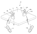
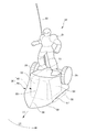
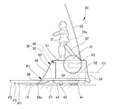
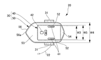
- FIG. 1 is an overall configuration diagram of a battle system using a battle traveling toy according to an embodiment of the present invention. It is a perspective view of the running toy for battle of the embodiment concerning the present invention. It is a side view of a running toy for battle. It is a rear view of the running toy for battle. It is a top view of the running toy for battle. It is a bottom view of the running toy for battle.
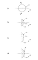
- FIGS. 5A and 5B are diagrams illustrating the shape of a protruding portion, where FIG. 4A is a view taken in the direction of an arrow A in FIG. 4, and FIGS. It is a figure to do.
- the fighting system 10 including the fighting toy according to the present invention includes a table 11 and a plurality (two in this case) of fighting toys 20, 20A that run on the running surface 12 of the table 11.
- the traveling toys 20, 20A are, for example, so-called radio controls that are wirelessly operated.
- a plurality of users operate the transmitters 13 and 13 ⁇ / b> A to move the traveling toys 20 and 20 ⁇ / b> A to contact or collide with the opponent traveling toys 20 and 20 ⁇ / b> A.
- the setting is such that the winning or losing is determined by tumbling the traveling toys 20, 20A within a predetermined time (the person who has tumbled the other traveling toy is the winner).
- winning / losing and superiority can also be determined by dropping the other party's running toys 20 and 20A from the base 12 or dropping the other party's doll bodies 21 and 21A.
- traveling toy 20 The configuration of the traveling toy 20 will be described in detail with reference to FIGS. Note that the traveling toy 20A has the same basic configuration as the traveling toy 20, and thus detailed description thereof is omitted.
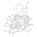
- the traveling toy 20 includes a toy body 30 and a doll body 21 that imitates a character that can be exchanged on the toy body 30.
- the toy main body 30 receives radio signals from a box-shaped chassis 40, a body 50 covering the chassis 40 from above, left and right projecting portions 31 projecting sideways from the body 50, and the transmitter 13 (see FIG. 1). And an antenna 22 for reception.
- the toy main body 30 can, for example, move straight (direction indicated by the arrow (1)) and pivot (direction indicated by the arrow (2)) and can move to a desired position.
- traveling means here, a pair of left and right wheels 41
- the wheel 41 is provided near the rear portion of the chassis 40 and is driven by driving means (not shown) such as an electric motor.
- driving means such as an electric motor.
- a support portion for example, a sliding member that slides on the traveling surface or a general driven wheel
- the travel means is not particularly limited to wheels, and any configuration is possible as long as the travel toy 20 can be moved relative to the travel surface 12.
- the chassis 40 is provided with a battery (for example, a dry battery) 43 and a battery box (not shown) for supplying power to the driving means. It is preferable that the battery 43 and the battery box are disposed at a position higher than the vertical center C1 of the toy main body 30. That is, by arranging the battery 43 having a relatively large mass among the components of the traveling toy 20 at a high position, the position of the center of gravity of the traveling toy 20 becomes high, so the traveling toy 20 becomes unstable and easily falls. .
- a battery for example, a dry battery
- a part of the chassis 40 (for example, an upper part or a lower part) is configured to be removable, and the battery 43 is replaced or various components are incorporated into the chassis 40 by using this part as a lid. Can do.
- the body 50 is detachably attached to the chassis 40.
- the body 50 has a substantially box shape that opens downward, and includes an upper wall 51 that covers the upper surface of the chassis 40, a side wall 52 that covers the side surface of the chassis 40, a front wall 53 that covers the front surface of the chassis 40, and a rear surface of the chassis 40. And a rear wall 54 for covering.
- the support body 32 extends upward from the upper wall 51.
- a predetermined portion of the doll body 21 (here, near the waist of the doll body 21) is detachably attached to the distal end portion 32a of the support body 32.
- the front wall 53 has an inclined portion 55 that is inclined downward and forward. At the front lower portion of the inclined portion 55, a rush portion 56 is provided that rushes into the lower portion of another traveling toy 20A (see FIG. 1) from the side.
- the entry portion 56 tapers forward and downward, and its sharp tip 56 a is close to the running surface 12.
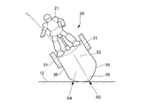
- the height position P1 of the tip 56a from the running surface 12 is preferably set lower than the height position P2 of the lower edge 57 of the side wall 52 (or the height position P3 of the lower surface 44 of the chassis).
- a gap 58 that opens to the side is formed in the lower portion of the toy main body 30.
- the gap 58 is a space formed between the traveling toy 20 and the traveling surface 12 and is formed from the lower edge 57 of the side wall to the lower surface 44 of the chassis.
- an entry portion 56A (see FIG. 1) of another traveling toy can enter.
- the left and right side walls 52 have a form that expands in the left-right direction as it goes downward.
- the side wall 52 is provided with an inwardly rounded radius R2, and the lower width dimension W1 of the left and right side walls 52 is set larger than the upper width dimension W2.
- the battery 43 may be disposed so as to be shifted to either the left or right side (here, the left side indicated by the arrow (3)) with respect to the center C2 in the left-right direction of the toy body 30.
- the traveling toy 20 easily falls down on the side where the battery 43 is disposed.
- positioned the battery 43 can be made into a weak point weak to a collision.
- the lower edge 59 of the front wall 53 is preferably formed so as to be bent outward in plan view.
- the lower edge 59 is formed in a substantially V shape so as to taper toward the tip in plan view.
- the roundness R3 is provided in the front-end
- size of roundness R3, R4 can be set arbitrarily.
- the lower edge 61 of the rear wall 54 may be provided with roundness R5, R6.
- the left and right wheels 41 are preferably arranged so as to be within the width dimension of the toy main body 30.
- the width dimension W3 of the left and right wheels 41 is set smaller than the width dimension W4 of the body 50 (more preferably, the width dimension W5 of the chassis 40).
- the protruding portion 31 has a substantially disk shape, and comes into contact with the protruding portion 31A (see FIG. 1) of another traveling toy when passing the other traveling toy.
- This protrusion 31 may be formed in a form (substantially semi-disc shape) only on the lower half side indicated by the arrow (4).
- it can apply also about the modification of the protrusion part 31 described below about the point which can be changed into a semicircular disk shape.
- the protrusion 31 may have a truncated cone shape in which a planar side surface 31a and a tapered outer peripheral surface 31b are combined.
- the protrusion part 31 may be the shape which combined the convex curved surface (for example, spherical surface) 31c curved outward and the taper-shaped outer peripheral surface 31d.
- the protruding portion 31 may have a shape in which the entire side surface is formed by a convex curved surface (for example, a spherical surface) 31e.
- the shape of the protrusion part 31 is not limited to these shapes, It can change arbitrarily according to the specification calculated
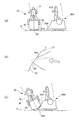
- FIG. 8 (a) when another traveling toy 20A travels toward the side of the traveling toy 20, as shown in FIG. 8 (b), the entry 56A of the other traveling toy 20A becomes a gap. The part 58 is plunged from the side.
- FIG. 8C when another traveling toy 20 ⁇ / b> A further moves forward, the entry portion 56 ⁇ / b> A enters so as to go between the traveling toy 20 and the traveling surface 12. Then, the traveling toy 20 rides on the inclined portion 55A and tilts. As a result, the traveling toy 20 falls in the direction indicated by the arrow (5).
- the traveling toy 20 and another traveling toy 20A pass each other, the protruding portion 31 and the protruding portion 31A collide as shown in FIG. 9B.
- the traveling toy 20 loses its independence stability and falls in the direction indicated by the arrow (6).
- the traveling toys 20 and 20A acting in this way the user can attack using the rush portions 56 and 56A or the protruding portions 31 and 31A to cause the opponent traveling toys 20 and 20A to fall.
- the operation until the winning or losing is determined is only the operation of running the traveling toys 20 and 20A and overturning the opponent traveling toys 20 and 20A. Therefore, according to this embodiment, it is possible to provide an interesting toy in which winning or losing is determined by a simple operation.
- the lower edge 59 of the front wall is formed to be curved outward.
- the toy of the traveling toy is prevented by the straight part and the corner part. That is, the traveling toy is difficult to roll.
- the traveling toy 20 since the round edges R3 and R4 are provided on the lower edge 59, the traveling toy 20 easily rolls the traveling surface 12 when it falls. As a result, the traveling toy 20 can be turned over more easily.
- the shape is easy to fall down, and the balance becomes unstable when the traveling toys collide with each other. Therefore, the operator himself / herself also actually owns the traveling toy or the opponent's traveling toy. It is possible to face a battle with a sense of urgency that it will not be determined whether or not it will fall until it falls, and it is possible to provide a highly competitive running toy for battle.
- the traveling toy 70 has a bar portion 23 that extends forward by a predetermined length L from the entry portion 56.
- the rod part 23 can be brought into contact with the other protrusion 31A.
- the other traveling toy 20A can be turned over in the direction of the arrow (7) by applying the tip of the rod portion 23 to the protruding portion 31A.
- the user can attack the opponent traveling toy 20 ⁇ / b> A also with the rod portion 23 in addition to the attack with the entry portion 56 and the protrusion portion 31.
- the traveling toy 80 is provided with an attachment portion 33 on the upper portion of the body 50, and a plurality of types of components can be detachably attached to the attachment portion 33.
- the user can attach the convex curved part 34 or remove the part 34 and attach the bar 23 (see FIG. 11) according to the content of the battle.
- the user can enjoy various battles using the replacement parts such as the parts 34 and the bar part 23 in addition to the attack by the rushing part 56 and the protruding part 31.
Landscapes
- Engineering & Computer Science (AREA)
- Multimedia (AREA)
- Computer Networks & Wireless Communication (AREA)
- Educational Technology (AREA)
- Toys (AREA)
Abstract
Description
図7(a)に示すように、突出部31は、略円盤状であり、他の走行玩具とすれ違うときに他の走行玩具の突出部31A(図1参照)と当接する。この突出部31は、矢印(4)で示す下半部側のみの形態(略半円盤状)に形成してもよい。このように半円盤状に変更可能である点については、以下に述べる突出部31の変形例についても適用可能である。
図11(a)に示すように、走行玩具70は、突入部56よりも所定長さLだけ前方に延びる棒部23を有する。棒部23は、相手の突出部31Aに当接可能である。図11(b)に示すように、棒部23の先端を突出部31Aに当てることで、相手の走行玩具20Aを矢印(7)の向きに転倒させることができる。この変更例によれば、使用者は、突入部56および突出部31による攻撃に加え、棒部23によっても相手の走行玩具20Aを攻撃することができる。
図12に示すように、走行玩具80は、ボディ50の上部に取り付け部33を設け、この取り付け部33に複数種の部品を着脱自在に取り付け可能としたものである。たとえば、使用者は、対戦内容に応じて、凸曲面状の部品34を取り付けたり、あるいは、部品34を外して棒部23(図11参照)を取り付けたりすることができる。これにより、使用者は、突入部56および突出部31による攻撃に加え、部品34や棒部23等の交換部品を使って、様々な対戦を楽しむことができる。
20,20A 対戦用走行玩具
23 棒部
30 玩具本体
31,31A 突出部
41 車輪(走行手段)
43 電池
56,56A 突入部
58 隙間部
70,80 対戦用走行玩具
C1 上下方向中心
C2 左右方向中心
W4 幅寸法
Claims (7)
- 走行手段が設けられた玩具本体を有する対戦用走行玩具であって、
前記玩具本体の前部には、前方に向けて先細り形状を有する突入部が設けられ、
前記玩具本体の下部には、側方に開放し、他の対戦用走行玩具の突入部が突入可能である隙間部が設けられることを特徴とする対戦用走行玩具。 - 請求項1において、
前記玩具本体から側方に突出する突出部を有し、
前記突出部は、他の対戦用走行玩具とすれ違うときに他の対戦用走行玩具の突出部と当接する対戦用走行玩具。 - 請求項2において、
前記突入部よりも前方に延びる棒部を有し、
前記棒部は、他の対戦用走行玩具の突出部に当接可能である対戦用走行玩具。 - 請求項1乃至請求項3のいずれか一項において、
前記走行手段を駆動するための電池を有し、
前記電池は、前記玩具本体の上下方向中心よりも高い位置に配置される対戦用走行玩具。 - 請求項1乃至請求項3のいずれか一項において、
前記走行手段を駆動するための電池を有し、
前記電池は、前記玩具本体の左右方向中心に対し、左右いずれかの側にずらして配置される対戦用走行玩具。 - 請求項1乃至請求項5のいずれか一項において、
前記走行手段は、左右の車輪で構成され、
前記車輪は、前記玩具本体の幅寸法内に収まるように配置される対戦用走行玩具。 - 請求項1乃至請求項6のいずれか一項において、
前記玩具本体の前部は、平面視で外側に湾曲して形成される対戦用走行玩具。
Priority Applications (2)
| Application Number | Priority Date | Filing Date | Title |
|---|---|---|---|
| US14/344,766 US20150147935A1 (en) | 2011-09-20 | 2012-09-19 | Battling mobile toy |
| KR1020147002902A KR20140037946A (ko) | 2011-09-20 | 2012-09-19 | 대전용 주행 완구 |
Applications Claiming Priority (2)
| Application Number | Priority Date | Filing Date | Title |
|---|---|---|---|
| JP2011205238A JP5044716B1 (ja) | 2011-09-20 | 2011-09-20 | 対戦用走行玩具 |
| JP2011-205238 | 2011-09-20 |
Publications (1)
| Publication Number | Publication Date |
|---|---|
| WO2013042672A1 true WO2013042672A1 (ja) | 2013-03-28 |
Family
ID=46469888
Family Applications (1)
| Application Number | Title | Priority Date | Filing Date |
|---|---|---|---|
| PCT/JP2012/073875 Ceased WO2013042672A1 (ja) | 2011-09-20 | 2012-09-19 | 対戦用走行玩具 |
Country Status (5)
| Country | Link |
|---|---|
| US (1) | US20150147935A1 (ja) |
| JP (1) | JP5044716B1 (ja) |
| KR (1) | KR20140037946A (ja) |
| CN (2) | CN202822770U (ja) |
| WO (1) | WO2013042672A1 (ja) |
Families Citing this family (7)
| Publication number | Priority date | Publication date | Assignee | Title |
|---|---|---|---|---|
| JP5553871B2 (ja) * | 2012-09-25 | 2014-07-16 | 株式会社バンダイ | 対戦ゲーム用ゲームピースおよび対戦ゲームセット |
| JP6479196B2 (ja) * | 2015-09-18 | 2019-03-06 | 有限会社イング二十一 | 走行玩具 |
| CN105617673B (zh) * | 2015-12-25 | 2017-12-01 | 杭州电子科技大学 | 转向轮摆动角行程及周期精密可调的无碳小车 |
| CN110302547B (zh) * | 2019-07-01 | 2024-06-07 | 奥飞娱乐股份有限公司 | 玩具对战系统 |
| CN110302548B (zh) * | 2019-07-01 | 2024-06-07 | 奥飞娱乐股份有限公司 | 对战设备及对战玩具的互动系统 |
| JP7300487B2 (ja) * | 2021-10-15 | 2023-06-29 | 株式会社バンダイ | 移動玩具 |
| USD1090732S1 (en) * | 2024-09-06 | 2025-08-26 | Liying Wang | Toy |
Citations (7)
| Publication number | Priority date | Publication date | Assignee | Title |
|---|---|---|---|---|
| JPH07116291A (ja) * | 1993-10-25 | 1995-05-09 | Takara Co Ltd | 弾き玩具 |
| JPH0734889U (ja) * | 1993-12-07 | 1995-06-27 | 株式会社タカラ | 弾き玩具 |
| JP3092360U (ja) * | 2002-08-27 | 2003-03-07 | 株式会社タカラ | おはじき玩具 |
| JP2003079964A (ja) * | 2001-09-14 | 2003-03-18 | Bandai Co Ltd | 玩具対戦システム及び対戦玩具 |
| JP2003527945A (ja) * | 2000-03-24 | 2003-09-24 | ティルバー、ニール | ジャイロスコープ動作をする複数の車輪を有する玩具車両 |
| JP2003311018A (ja) * | 2002-04-19 | 2003-11-05 | Uizu:Kk | 格闘型ゲーム用玩具のゲーム台 |
| JP4588115B1 (ja) * | 2010-04-01 | 2010-11-24 | 株式会社バンダイ | 走行玩具 |
Family Cites Families (6)
| Publication number | Priority date | Publication date | Assignee | Title |
|---|---|---|---|---|
| US3932957A (en) * | 1975-02-12 | 1976-01-20 | Marvin Glass & Associates | Toy vehicle |
| US7291054B2 (en) * | 2002-10-23 | 2007-11-06 | Silverlit Toys Manufactory, Ltd. | Toy with programmable remote control |
| US6672937B1 (en) * | 2002-12-23 | 2004-01-06 | Stephen J. Motosko | Miniature toy vehicle |
| US6746304B1 (en) * | 2003-04-14 | 2004-06-08 | Shu-Ming Liu | Remote-control toy car set |
| US7938709B2 (en) * | 2008-06-26 | 2011-05-10 | Vladimir Leonov | Steering mechanism for a toy vehicle |
| US20120178339A1 (en) * | 2011-01-11 | 2012-07-12 | Mimlitch Iii Robert H | Moving Attachments for a Vibration Powered Toy |
-
2011
- 2011-09-20 JP JP2011205238A patent/JP5044716B1/ja active Active
-
2012
- 2012-03-23 CN CN2012201144143U patent/CN202822770U/zh not_active Expired - Fee Related
- 2012-03-23 CN CN2012100802200A patent/CN102580321A/zh active Pending
- 2012-09-19 US US14/344,766 patent/US20150147935A1/en not_active Abandoned
- 2012-09-19 KR KR1020147002902A patent/KR20140037946A/ko not_active Abandoned
- 2012-09-19 WO PCT/JP2012/073875 patent/WO2013042672A1/ja not_active Ceased
Patent Citations (7)
| Publication number | Priority date | Publication date | Assignee | Title |
|---|---|---|---|---|
| JPH07116291A (ja) * | 1993-10-25 | 1995-05-09 | Takara Co Ltd | 弾き玩具 |
| JPH0734889U (ja) * | 1993-12-07 | 1995-06-27 | 株式会社タカラ | 弾き玩具 |
| JP2003527945A (ja) * | 2000-03-24 | 2003-09-24 | ティルバー、ニール | ジャイロスコープ動作をする複数の車輪を有する玩具車両 |
| JP2003079964A (ja) * | 2001-09-14 | 2003-03-18 | Bandai Co Ltd | 玩具対戦システム及び対戦玩具 |
| JP2003311018A (ja) * | 2002-04-19 | 2003-11-05 | Uizu:Kk | 格闘型ゲーム用玩具のゲーム台 |
| JP3092360U (ja) * | 2002-08-27 | 2003-03-07 | 株式会社タカラ | おはじき玩具 |
| JP4588115B1 (ja) * | 2010-04-01 | 2010-11-24 | 株式会社バンダイ | 走行玩具 |
Also Published As
| Publication number | Publication date |
|---|---|
| JP2013066514A (ja) | 2013-04-18 |
| CN102580321A (zh) | 2012-07-18 |
| US20150147935A1 (en) | 2015-05-28 |
| KR20140037946A (ko) | 2014-03-27 |
| CN202822770U (zh) | 2013-03-27 |
| JP5044716B1 (ja) | 2012-10-10 |
Similar Documents
| Publication | Publication Date | Title |
|---|---|---|
| JP5044716B1 (ja) | 対戦用走行玩具 | |
| JP5496961B2 (ja) | ゲームプログラムおよびゲーム装置 | |
| CN201969332U (zh) | 可变形玩具 | |
| JP6975683B2 (ja) | 情報処理プログラム、情報処理装置、情報処理システム、および情報処理方法 | |
| JP6925879B2 (ja) | ゲームプログラム、情報処理装置、情報処理システム、および、ゲーム処理方法 | |
| CN103566593A (zh) | 一种可弹跳的玩具陀螺 | |
| JP3109118U (ja) | コマ玩具 | |
| JP2013066699A (ja) | 対戦用走行玩具 | |
| JP5054154B2 (ja) | 操作コマと、操作コマを使ったサッカー遊戯具、スラローム遊戯具、喧嘩ゴマ遊戯具、およびジャンプ遊戯具 | |
| CN107715463A (zh) | 对战用行走玩具 | |
| JP4409964B2 (ja) | 遠隔制御走行玩具を用いた遊戯玩具装置 | |
| CN203540045U (zh) | 一种可弹跳的玩具陀螺 | |
| JP2018202097A (ja) | ゲームプログラムおよびゲーム装置 | |
| JP2007111144A (ja) | コマ玩具 | |
| JP2017070600A (ja) | 対戦玩具 | |
| JP2003311018A (ja) | 格闘型ゲーム用玩具のゲーム台 | |
| JP3205781U (ja) | ゲーム盤 | |
| WO2011102069A1 (ja) | 駒及びゲーム盤を備えたゲーム玩具 | |
| JP2000093659A5 (ja) | ||
| CN203736845U (zh) | 对战遥控玩具车 | |
| JPH0568588U (ja) | ゲーム玩具 | |
| KR100540751B1 (ko) | 탑승자에 의한 흔들림을 이용하는 놀이기구 | |
| CN203408481U (zh) | 一种便于练习侧翻和侧滑的手指滑板玩具 | |
| CN207055906U (zh) | 滚球游戏机 | |
| JP4185938B2 (ja) | 飛翔玩具 |
Legal Events
| Date | Code | Title | Description |
|---|---|---|---|
| 121 | Ep: the epo has been informed by wipo that ep was designated in this application |
Ref document number: 12833664 Country of ref document: EP Kind code of ref document: A1 |
|
| ENP | Entry into the national phase |
Ref document number: 20147002902 Country of ref document: KR Kind code of ref document: A |
|
| NENP | Non-entry into the national phase |
Ref country code: DE |
|
| WWE | Wipo information: entry into national phase |
Ref document number: 14344766 Country of ref document: US |
|
| 122 | Ep: pct application non-entry in european phase |
Ref document number: 12833664 Country of ref document: EP Kind code of ref document: A1 |