WO2013042293A1 - 充電式電気機器 - Google Patents
充電式電気機器 Download PDFInfo
- Publication number
- WO2013042293A1 WO2013042293A1 PCT/JP2012/003823 JP2012003823W WO2013042293A1 WO 2013042293 A1 WO2013042293 A1 WO 2013042293A1 JP 2012003823 W JP2012003823 W JP 2012003823W WO 2013042293 A1 WO2013042293 A1 WO 2013042293A1
- Authority
- WO
- WIPO (PCT)
- Prior art keywords
- charge
- charging
- trickle
- value
- current
- Prior art date
Links
Images


Classifications
-
- H—ELECTRICITY
- H02—GENERATION; CONVERSION OR DISTRIBUTION OF ELECTRIC POWER
- H02J—CIRCUIT ARRANGEMENTS OR SYSTEMS FOR SUPPLYING OR DISTRIBUTING ELECTRIC POWER; SYSTEMS FOR STORING ELECTRIC ENERGY
- H02J7/00—Circuit arrangements for charging or depolarising batteries or for supplying loads from batteries
- H02J7/02—Circuit arrangements for charging or depolarising batteries or for supplying loads from batteries for charging batteries from ac mains by converters
- H02J7/04—Regulation of charging current or voltage
-
- H—ELECTRICITY
- H01—ELECTRIC ELEMENTS
- H01M—PROCESSES OR MEANS, e.g. BATTERIES, FOR THE DIRECT CONVERSION OF CHEMICAL ENERGY INTO ELECTRICAL ENERGY
- H01M10/00—Secondary cells; Manufacture thereof
- H01M10/42—Methods or arrangements for servicing or maintenance of secondary cells or secondary half-cells
- H01M10/44—Methods for charging or discharging
- H01M10/448—End of discharge regulating measures
-
- H—ELECTRICITY
- H02—GENERATION; CONVERSION OR DISTRIBUTION OF ELECTRIC POWER
- H02J—CIRCUIT ARRANGEMENTS OR SYSTEMS FOR SUPPLYING OR DISTRIBUTING ELECTRIC POWER; SYSTEMS FOR STORING ELECTRIC ENERGY
- H02J7/00—Circuit arrangements for charging or depolarising batteries or for supplying loads from batteries
- H02J7/0029—Circuit arrangements for charging or depolarising batteries or for supplying loads from batteries with safety or protection devices or circuits
- H02J7/00304—Overcurrent protection
-
- H—ELECTRICITY
- H02—GENERATION; CONVERSION OR DISTRIBUTION OF ELECTRIC POWER
- H02J—CIRCUIT ARRANGEMENTS OR SYSTEMS FOR SUPPLYING OR DISTRIBUTING ELECTRIC POWER; SYSTEMS FOR STORING ELECTRIC ENERGY
- H02J7/00—Circuit arrangements for charging or depolarising batteries or for supplying loads from batteries
- H02J7/007—Regulation of charging or discharging current or voltage
-
- H—ELECTRICITY
- H01—ELECTRIC ELEMENTS
- H01M—PROCESSES OR MEANS, e.g. BATTERIES, FOR THE DIRECT CONVERSION OF CHEMICAL ENERGY INTO ELECTRICAL ENERGY
- H01M2220/00—Batteries for particular applications
- H01M2220/30—Batteries in portable systems, e.g. mobile phone, laptop
-
- H—ELECTRICITY
- H02—GENERATION; CONVERSION OR DISTRIBUTION OF ELECTRIC POWER
- H02J—CIRCUIT ARRANGEMENTS OR SYSTEMS FOR SUPPLYING OR DISTRIBUTING ELECTRIC POWER; SYSTEMS FOR STORING ELECTRIC ENERGY
- H02J7/00—Circuit arrangements for charging or depolarising batteries or for supplying loads from batteries
- H02J7/0029—Circuit arrangements for charging or depolarising batteries or for supplying loads from batteries with safety or protection devices or circuits
- H02J7/00302—Overcharge protection
-
- Y—GENERAL TAGGING OF NEW TECHNOLOGICAL DEVELOPMENTS; GENERAL TAGGING OF CROSS-SECTIONAL TECHNOLOGIES SPANNING OVER SEVERAL SECTIONS OF THE IPC; TECHNICAL SUBJECTS COVERED BY FORMER USPC CROSS-REFERENCE ART COLLECTIONS [XRACs] AND DIGESTS
- Y02—TECHNOLOGIES OR APPLICATIONS FOR MITIGATION OR ADAPTATION AGAINST CLIMATE CHANGE
- Y02E—REDUCTION OF GREENHOUSE GAS [GHG] EMISSIONS, RELATED TO ENERGY GENERATION, TRANSMISSION OR DISTRIBUTION
- Y02E60/00—Enabling technologies; Technologies with a potential or indirect contribution to GHG emissions mitigation
- Y02E60/10—Energy storage using batteries
Definitions
- the present invention relates to a rechargeable electric device capable of rapidly charging a built-in secondary battery, and more particularly to a rechargeable electric device having a trickle charge function.
- Ni-MH nickel-metal hydride batteries
- the charge function in rechargeable electric devices has also evolved, and quick charging with a larger charging current than conventional charging current completes charging in a shorter time than conventional rechargeable electric devices
- the number of rechargeable electrical devices is increasing significantly.
- the charging current at the time of rapid charging is to compensate for the natural discharge of the battery even after rapid charging and to activate the inactive battery.
- Charging was continued with a minute current having a constant current value smaller than the value. Charging with a minute current having a constant current value is referred to as trickle charging.
- the microcomputer has a function (remaining capacity detection function) for detecting the remaining capacity of the secondary battery, and the microcomputer has 100% remaining capacity (full charge). There are many cases where the charging of the secondary battery is terminated when it is detected.
- the microcomputer is always started, and at least the charge current amount charged to the secondary battery and the secondary battery discharged to the load Since it is necessary to manage the amount of discharge current, power consumption by the microcomputer becomes a problem.
- Ni-MH Nickel metal hydride
- a nickel metal hydride battery As a secondary battery is almost fully charged when the battery voltage value exceeds the peak value and becomes lower than the peak value during charging. It has the characteristic of becoming a state.
- the microcomputer detects that the value of the battery voltage exceeds the peak value and becomes lower than the peak value, it is fully charged. It has been determined that the rapid charging has ended, and it has been increased (see Patent Document 1).
- this rechargeable electric device unlike the above-described conventional rechargeable electric device having a remaining capacity detection function, there is no need to constantly activate the microcomputer to manage the amount of charging current and the amount of discharging current. It is possible to reduce power consumption.
- the nickel hydrogen battery hereinafter referred to Active batteries can not be fully charged only by rapid charging.
- the conventional device of this type continuously carries out trickle charge after rapid charging, thereby activating the inactive battery and performing bidirectional activation in the diagram.
- the secondary battery was charged to a fully charged state by compensating for the capacity that could not be charged by quick charging, as indicated by the arrows.
- the current value of the trickle charge current necessary to activate (while charging) the inactive battery is larger than the current value of the trickle charge current necessary to compensate for the natural discharge of the battery. Therefore, once the inactive battery is activated and charged to the fully charged state, it should be possible to perform trickle charge with a charge current of a smaller value than before. Nevertheless, in the case of rechargeable electric equipment that continues trickle charge after conventional quick charge, the trickle charge current of constant current value necessary for activating and charging inactive battery after quick charge The power consumption is wasted because the
- the present invention solves the above-mentioned problems, and in trickle charging, a rechargeable electric device capable of charging while activating an inactive battery and capable of suppressing power consumption necessary for charging. Intended to be provided.
- a rechargeable electric device comprises a rechargeable secondary battery, a switching element provided between the secondary battery and a power supply, and a time measuring means for measuring time.
- the charging current for charging the secondary battery by controlling the duty ratio which is the ratio of the on time and the off time of the switching element based on the time output from the time measuring means.
- the charging to the secondary battery is performed by a rapid charging and a charging current at the time of the rapid charging of the secondary battery after the termination of the rapid charging.
- trickle charge for charging with a small current and the control means is configured to charge current in the first trickle charge after the end of the rapid charge and charge in the second and subsequent trickle charges. And wherein varying the value of the current.
- the value of the charge current in the first trickle charge after the end of the rapid charge and the value of the charge current in the second and subsequent trickle charges are made different.
- charging is performed with a charging current of a current value necessary to activate and charge the inactive battery
- the second and subsequent trickle charges the battery is naturally discharged.
- Charging can be performed with a charging current of a current value necessary to compensate for Therefore, in the first trickle charge, charging can be performed while activating the inactive battery.
- charging is performed while activating the inactive battery as in the prior art by charging with a charging current of a current value necessary to compensate for the natural discharge of the battery. Power consumption required for charging can be reduced as compared with the case where trickle charging is continued at a constant current value necessary for
- the control means inserts a charging pause time between the quick charge and the first trickle charge or / and between the first and subsequent trickle charges. May be
- control means sets the value of the charging current in the second and subsequent trickle charges to a value lower than the value of the charging current in the first trickle charge.
- the circuit block diagram of the electric shaver which is a charge-type electric equipment which concerns on one Embodiment of this invention, and an adapter.
- the electric shaver WHEREIN The graph which shows the pattern of a rapid charge and a trickle charge in the case where an ordinary battery is charged, and the case where an inactive battery is charged.
- FIG. 1 shows a circuit configuration of an electric shaver 1 of the present embodiment (a rechargeable electric device in the claims) and an adapter 11 connected to the electric shaver 1 at the time of charging.
- the electric shaver 1 is a chargeable electric shaver, and is a load terminal motor 2, a rechargeable secondary battery 3 for supplying power to the motor 2, and a charging terminal electrically connected to the secondary battery 3. 4a and 4b are provided.
- the secondary battery 3 is configured by connecting in series a plurality of nickel hydrogen batteries having a standard battery voltage value of 1.4V.
- the electric shaver 1 includes a microcomputer 5 (control means) for controlling the entire apparatus and a switching element 6.
- the microcomputer 5 has a timer 8 (time measuring means) for measuring time, and based on the time output from the timer 8, a duty ratio which is a ratio of the on time of the switching element 6 to the off time is By controlling, the value of the charging current for charging the secondary battery 3 is controlled. Further, the microcomputer 5 keeps the switching element 6 in the off state for a predetermined time based on the time output from the timer 8 to thereby perform the quick charge and the first trickle charge after the quick charge. And / or between the first and subsequent trickle charges after the quick charge, charging pause time may be inserted.
- the switching element 6 is an n-channel enhancement type MOSFET (Metal Oxide Semiconductor Field Effect Transistor).
- the switching element 6 is provided between the secondary battery 3 and the adapter 11 (that is, between the secondary battery 3 and the commercial power supply 20).
- Switching element 6 cuts off a path connecting charging terminal 4a to the + side of secondary battery 3 in accordance with high / low of the voltage level of the control signal input to the gate from microcomputer 5 via line L5 (see FIG. Switch between off) and connection (on). Specifically, when the voltage level of the control signal input to the gate of switching element 6 is high, the drain and source of switching element 6 conduct, and charging terminal 4 a and the positive side of secondary battery 3 The connecting path is connected to charge the secondary battery 3.
- MOSFET Metal Oxide Semiconductor Field Effect Transistor
- Lines L0 to L5 are connected to a plurality of input / output terminals (not shown) of the microcomputer 5, respectively.
- the line L0 is an input line for detecting a charging current value to the secondary battery 3.
- the microcomputer 5 flows the current input to the line L0 to the resistor provided inside the microcomputer, measures the value of voltage drop due to this resistance, and charges the secondary battery 3 based on the value of the voltage drop. Detect (determine) the current value.
- the line L1 is an input line for detecting the voltage value on the positive side of the secondary battery 3.
- a ground line (hereinafter, referred to as a GND line) L2 is an input line for detecting a voltage value on the negative side of the secondary battery 3.
- the microcomputer 5 detects the value of the battery voltage of the secondary battery 3 based on the voltage applied to the line L1 and the voltage applied to the GND line L2.
- Line L3 is an input line for power supply that connects the secondary battery 3 and the microcomputer 5. Furthermore, the line L4 is an input line for detecting a discharge current value discharged from the secondary battery 3 to the motor 2.
- the microcomputer 5 flows the current input to the line L4 to a resistor provided inside the microcomputer, measures the value of the voltage drop due to this resistance, and based on the value of the voltage drop, the discharge current value to the motor 2 To detect (determine) Then, the microcomputer 5 prevents an overcurrent from flowing to the motor 2 which is a load, based on the detected discharge current value.
- the line L5 is an output line of a control signal for switching connection and disconnection of a (charging) path connecting the charging terminal 4a and the + side of the secondary battery 3.
- the microcomputer 5 adjusts (changes) the duty ratio which is the ratio of the on time and the off time of the switching element 6 according to the level of the charging current detected based on the current input to the line L0.
- the value of the charging current for charging the secondary battery 3 is feedback controlled.
- the electric shaver 1 further includes an operation switch 7. At the time of use of the electric shaver 1, when the operation switch 7 is turned on by the user and short-circuited, the secondary battery 3 and the motor 2 are electrically connected, and power from the secondary battery 3 to the motor 2 is supplied. Is supplied to drive the motor 2.
- the adapter 11 is a switching power supply that converts AC power (voltage) of the commercial power supply 20 into DC power (voltage) and supplies power (power) to the electric shaver 1.
- the adapter 11 has connection terminals 12 a and 12 b for connection to the commercial power supply 20, and power supply terminals 17 a and 17 b for connection (with power supply) to the electric shaver 1.
- the adapter 11 When charging the secondary battery 3, the adapter 11 has the connection terminals 12 a and 12 b connected to the commercial power supply 20, and the power supply terminals 17 a and 17 b connected to the electric shaver 1 to supply AC power supplied from the commercial power supply 20. Supply DC power to the electric shaver 1.
- the adapter 11 smoothes the DC voltage of the pulsating current output from the diode bridge 13 and the diode bridge 13 for converting the AC voltage input from the commercial power supply 20 into the DC voltage of the pulsating current, and the voltage is substantially constant. And a smoothing capacitor C1 for converting into a direct current voltage.
- the adapter 11 further includes a control circuit 14 that controls the entire adapter and a step-down circuit 15 that steps down a DC voltage supplied via the smoothing capacitor C1.
- the control circuit 14 operates based on the power of the DC voltage supplied via the diode bridge 13 and the smoothing capacitor C1.
- the step-down circuit 15 includes a step-down transformer 18 and a transistor 16 for switching between application and non-application of voltage to the primary coil of the transformer 18.
- the transistor 16 is an NPN type bipolar transistor.
- the control circuit 14 switches between conduction (ON) and non-conduction (OFF) between the collector and emitter of the transistor 16 by switching high / low of the voltage level applied to the base of the transistor 16 through the output line L7. .
- the control circuit 14 switches between application and non-application of voltage to the primary coil of the transformer 18 by switching between conduction and non-conduction between the collector and emitter of the transistor 16.
- the control circuit 14 controls the ratio of the high time to the low time of the voltage level applied to the base of the transistor 16 so that the time of conduction (ON) between the collector and the emitter (OFF) Control the ratio to the time (so-called duty ratio).
- the control circuit 14 controls the voltage of the power output from the secondary coil of the transformer 18 to a substantially constant value.
- the adapter 11 also has a transformer 19 for detecting the voltage level induced in the secondary coil of the transformer 18.
- the control circuit 14 detects the value of the voltage induced in the transformer 19 through the input line L8 and the GND line L9, and based on the detected voltage value of the transformer 19, the voltage applied to the base of the transistor 16 Feedback control is performed on the duty ratio.
- the adapter 11 receives the pulse-like power output from the secondary coil of the transformer 18, and the diode D1 for backflow prevention and the smoothing capacitor for smoothing the voltage value of the power output from the diode D1. It is further equipped with C2.
- the trickle charging method in the electric shaver 1 of the present embodiment will be described.
- the microcomputer 5 sets the value (50 mA) of the charging current in the second and subsequent trickle charges to a value lower than the value (100 mA) of the charging current in the first trickle charge.
- the value (100 mA) of the charging current in the first trickle charge is the current value necessary for charging while activating the nickel hydrogen battery (hereinafter referred to as inactive battery) in the inactive state. It is.
- the value (50 mA) of the charging current in the second and subsequent trickle charging is a current value of the trickle charging current necessary to compensate for the natural discharge of the battery.
- the microcomputer 5 does not insert a charging pause time between the quick charge and the first trickle charge (the pause time after the quick charge is set to 0 hours). However, the pause time of charge is inserted between the first and subsequent trickle charges. Specifically, the microcomputer 5 controls the switching element 6 to rapidly charge the battery at a current value of 1000 mA for 1 hour, and then shifts to the first trickle charge without stopping the charge. Then, in the first trickle charge, after charging for 8 hours at a current value of 100 mA, charging is paused for 3.5 hours.
- the microcomputer 5 repeats the 2.5-hour charging process with the current value of 50 mA in each of the second and subsequent trickle charges and the 3.5-hour charging suspension process thereafter. Note that the pause time inserted between the first and subsequent trickle charges does not affect the use of the electric shaver 1 (the electric shaver 1 can not be used due to natural discharge or power consumption by the microcomputer 5). (Short enough time to prevent).
- FIG. 3 is a graph showing patterns of quick charge and trickle charge in the case of charging an ordinary battery and in the case of charging an inactive battery in the electric shaver 1.
- the electric shaver 1 also rapidly charges when the value of the battery voltage exceeds the peak value and becomes lower than the peak value, as shown in FIG.
- the microcomputer 5 of the electric shaver 1 is, as shown in the lower part of FIG. Charge for 8 hours with the current value (100 mA) required to charge while activating.
- the microcomputer 5 activates the inactive secondary battery 3 and compensates for the capacity which can not be charged by the quick charge, as indicated by the double-headed arrow in FIG.
- the secondary battery 3 is once charged to a fully charged state.
- the microcomputer 5 performs charging for compensating for the natural discharge of the battery in each of the second and subsequent trickle charges.
- the secondary battery 3 to be charged is charged by charging with the current value necessary for charging while activating the inactive battery. Even when inactive, it can be fully charged.
- the secondary battery 3 to be charged is a normal battery
- the secondary battery 3 is charged to a nearly fully charged state by quick charging, so that charging of the first trickle charge
- the purpose is mainly to compensate for the natural discharge of the battery.
- the pattern of the trickle charge shown in FIG. 4 is different from the pattern of the trickle charge shown in FIG. 2 in that a pause time for charging is inserted also between the quick charge and the first trickle charge. .
- the other points are basically the same as the trickle charge pattern shown in FIG.
- the time of the first trickle charge is shown in FIG. It is desirable to make it longer than the first trickle charge time (8 hours).
- the pause time inserted between the above-mentioned quick charge and the first trickle charge is set to a time that does not affect activation of secondary battery 3 (a time short enough not to affect activation). Ru.
- the trickle charge pattern shown in FIG. 5 is different from the trickle charge pattern shown in FIG. 4 in that no charging rest time is inserted between the first and subsequent trickle charges. .
- the other points are basically the same as the trickle charge pattern shown in FIG.
- the second trickle charge is performed by continuing the second trickle charge without inserting the charging pause time between the first and subsequent trickle charges. Total time for charging increases.
- the current value (20 mA) of the second trickle charge is set to the second and subsequent trickle charges in FIG. It is smaller than the charging current value (50 mA).
- the trickle charge pattern shown in FIG. 6 is different from the trickle charge pattern shown in FIG. 2 in that no charging rest time is inserted between the first and subsequent trickle charges. There is.
- the other points are basically the same as the trickle charge pattern shown in FIG.
- the second trickle charge is performed by continuing the second trickle charge without inserting the charging pause time between the first and subsequent trickle charges. Total time for charging increases.
- the current value (20 mA) of the second trickle charge is set to the second and subsequent trickle charges in FIG. It is smaller than the charging current value (50 mA).
- the trickle charge pattern shown in FIG. 7 is that the current value (75 mA) of the second trickle charge is higher than the current value (50 mA) of the third trickle charge.
- the other points are basically the same as the trickle charge pattern shown in FIG.
- the fourth and subsequent trickle charge current values may be lower than the third trickle charge current value (50 mA), and the same as the third trickle charge current value. It is also good.
- the value of the charging current in the second and subsequent trickle charges is set to a value lower than the value of the charging current in the first trickle charge. More specifically, in the first trickle charge, charging is performed with a charge current of a current value necessary to activate and charge the inactive battery, and in the second and subsequent trickle charges, the battery is naturally It was made to charge by the charge current of the electric current value required to supplement discharge. Therefore, in the first trickle charge, charging can be performed while activating the inactive battery.
- the microcomputer 5 is between the quick charge and the first trickle charge. And / or between the first and subsequent trickle charges, a charging pause time is inserted. This makes it possible to further reduce the power consumption necessary for charging, as compared to the case where trickle charging is continued at a constant current value, which is necessary for charging while activating an inactive battery as in the prior art. Become.
- the present invention is not limited to the configuration of the above embodiment, and various modifications can be made without departing from the scope of the invention.
- the rechargeable electric device of the present invention is the electric shaver 1
- the present invention is applied to a rechargeable electric device such as a mobile phone or a portable information device.
- the secondary battery included in the rechargeable electric device of the present invention is not necessarily limited to the nickel hydrogen battery.
- the switching element 6 is a MOSFET is shown, but the switching element 6 may be a bipolar transistor.
Abstract
急速充電の終了後の第1回目のトリクル充電における充電電流の値と、第2回目以降のトリクル充電における充電電流の値とを異ならせるようにした。これにより、例えば、第1回目のトリクル充電では、不活性電池を活性化させつつ充電するために必要な電流値の充電電流で充電を行い、第2回目以降のトリクル充電では、電池の自然放電を補うために必要な電流値の充電電流で充電を行うようにすることができる。第2回目以降のトリクル充電において、電池の自然放電を補うために必要な電流値の充電電流で充電を行うようにしたことにより、従来のように不活性電池を活性化させつつ充電するために必要な、一定の電流値でトリクル充電を継続した場合と比べて、充電に必要な消費電力を抑えることが可能になる。
Description
本発明は、内蔵の二次電池に急速充電可能な充電式電気機器に係り、特に、トリクル充電機能を有する充電式電気機器に関する。
近年、電気シェーバ等のポータブルタイプの充電式電気機器の発達に伴い、ニッケル水素電池(Ni-MH:Nickel metal hydride)が、二次電池として広く使用されるようになってきている。ニッケル水素電池の普及によって、充電式電気機器における充電機能も進化してきており、従来の充電電流よりも大きな充電電流で急速充電することにより、従来の充電式電気機器よりも短い時間で充電を完了する充電式電気機器が著しく増加している。このニッケル水素電池を二次電池として用いる充電式電気機器では、急速充電後も、電池の自然放電を補うためと、不活性状態になった電池を活性化させるために、急速充電時の充電電流値よりも小さな一定の電流値を有する微小電流で充電を継続していた。この一定の電流値を有する微小電流による充電は、トリクル充電という。
ところで、一般に、二次電池を備えた充電式電気機器では、二次電池の発熱や破裂を防ぐために、二次電池の過充電を防ぐ必要がある。そこで、従来、この種の充電式電気機器では、二次電池の残容量を検出する機能(残容量検出機能)をマイコンに持たせて、マイコンが、残容量が100%(満充電)になったことを検出したときに、二次電池への充電を終了させるものが多かった。けれども、上記の残容量検出機能を用いた満充電の検出方法では、マイコンを常時起動させて、少なくとも、二次電池に充電された充電電流量と、二次電池から負荷に対して放電された放電電流量とを管理する必要があるので、マイコンによる電力消費が問題になる。
一方、二次電池としてのニッケル水素電池(Ni-MH:Nickel metal hydride)には、充電時に、その電池電圧の値がピーク値を越えてピーク値より低い値になったときにほぼ満充電の状態になるという特性がある。この特性を利用して、ニッケル水素電池を用いた充電式電気機器において、マイコンが、電池電圧の値がピーク値を越えてピーク値より低い値になったことを検出したときに、満充電になったと判定して、急速充電を終了させるものが増えている(特許文献1参照)。この充電式電気機器によれば、上記のような従来の残容量検出機能を有する充電式電気機器と異なり、マイコンを常時起動させて充電電流量と放電電流量とを管理する必要がないので、消費電力を削減することが可能である。
ところが、上記の電池電圧の値がピーク値を越えてピーク値より低い値になったときに急速充電を終了させる方式の充電式電気機器では、不活性状態になったニッケル水素電池(以下、不活性電池と略す)を、急速充電だけでは満充電の状態にすることができない。
上記の点について、図8を参照して説明する。不活性状態になっていない通常の電池は、急速充電を継続すると、上記のように電池電圧の値がピーク値を越えてピーク値より低い値になったとき(例えば図に示される充電開始から60分後)に、ほぼ満充電の状態になる。ところが、一般に、不活性電池に対して急速充電を行った場合には、充電開始から一定の時間以内に、上記の満充電に対応した電池電圧のピークとは異なる、電池電圧のピークを示すことが多い。このため、従来のこの種の機器は、電池電圧が上記の本来のピークとは異なるピークを越えたとき(例えば図中の充電開始から5分後)に、二次電池が満充電の状態になったと誤検出してしまい、満充電になる前に急速充電を終了してしまうことが多かった。この不活性電池で発生する充電不足への対策として、従来のこの種の機器は、急速充電後に、トリクル充電を継続して行うことにより、不活性電池の活性化をさせつつ、図中の両方向矢印で示される、急速充電で充電できなかった容量を補い、二次電池を満充電の状態まで充電していた。
けれども、上記従来の急速充電後にトリクル充電を継続して行う充電式電気機器では、不活性電池を活性化させながら充電するためと、電池の自然放電を補うための両方の目的で、急速充電後に一定の電流値のトリクル充電電流を流し続けていた。このため、以下の問題があった。
一般に、不活性電池を活性化させ(ながら充電す)るために必要なトリクル充電電流の電流値は、電池の自然放電を補うために必要なトリクル充電電流の電流値よりも大きい。従って、不活性電池を一旦活性化して満充電の状態まで充電した後には、それまでよりも小さな値の充電電流でトリクル充電を行えばよいはずである。にもかかわらず、従来の急速充電後にトリクル充電を継続して行う充電式電気機器では、急速充電後に、不活性電池を活性化させつつ充電するために必要な、一定の電流値のトリクル充電電流を流し続けていたため、消費電力に無駄が生じる。
本発明は、上記課題を解決するものであり、トリクル充電において、不活性電池を活性化させつつ充電することができ、しかも、充電に必要な消費電力を抑えることが可能な充電式電気機器を提供することを目的とする。
上記課題を解決するために、本発明の充電式電気機器は、充電可能な二次電池と、前記二次電池と電源との間に設けられたスイッチング素子と、時間を計測する時間計測手段を有し、この時間計測手段から出力された時間に基づいて、前記スイッチング素子のオンの時間とオフの時間との比率であるデューティ比を制御することにより、前記二次電池に充電する充電電流の値を制御する制御手段とを備えた充電式電気機器において、前記二次電池への充電は、急速充電と、この急速充電の終了後の前記二次電池を、前記急速充電時の充電電流よりも小さな値の電流で充電するためのトリクル充電とを含み、前記制御手段は、前記急速充電の終了後の第1回目のトリクル充電における充電電流の値と、第2回目以降のトリクル充電における充電電流の値とを異ならせることを特徴とする。
上記構成においては、急速充電の終了後の第1回目のトリクル充電における充電電流の値と、第2回目以降のトリクル充電における充電電流の値とを異ならせるようにした。これにより、例えば、第1回目のトリクル充電では、不活性電池を活性化させつつ充電するために必要な電流値の充電電流で充電を行い、第2回目以降のトリクル充電では、電池の自然放電を補うために必要な電流値の充電電流で充電を行うようにすることができる。従って、第1回目のトリクル充電では、不活性電池を活性化させつつ充電することができる。また、第2回目以降のトリクル充電では、電池の自然放電を補うために必要な電流値の充電電流で充電を行うようにしたことにより、従来のように不活性電池を活性化させつつ充電するために必要な、一定の電流値でトリクル充電を継続した場合と比べて、充電に必要な消費電力を抑えることが可能になる。
この充電式電気機器において、前記制御手段が、前記急速充電と前記第1回目のトリクル充電との間、又は/及び前記第1回目以降の各トリクル充電の間に、充電の休止時間を挿入してもよい。
この充電式電気機器において、前記制御手段が、前記第2回目以降のトリクル充電における充電電流の値を、前記第1回目のトリクル充電における充電電流の値よりも低い値にすることが望ましい。
以下、本発明の一実施形態に係る充電式電気機器である電気シェーバ1について、図面を参照して説明する。図1は、本実施形態の電気シェーバ1(請求項における充電式電気機器)と、充電時に電気シェーバ1に接続されるアダプタ11との回路構成を示す。電気シェーバ1は、充電式の電気シェーバであり、負荷であるモータ2と、このモータ2に電力を供給する充電可能な二次電池3と、二次電池3と電気的に接続された充電端子4a,4bとを備えている。二次電池3は、標準的な電池電圧の値が1.4Vのニッケル水素電池を、複数個直列に接続して構成したものである。複数のニッケル水素電池から構成される二次電池3は、活性状態では、その残容量が一定の閾値未満の状態から充電させていった場合に、その電池電圧の値がピーク値を越えてピーク値より低い値になったときにほぼ満充電の状態になるという特性を有する。本電気シェーバ1における二次電池3への充電には、急速充電と、この急速充電の終了後の二次電池3を、急速充電時の充電電流よりも小さな値の電流で充電するためのトリクル充電とが含まれている。
上記の電気シェーバ1は、装置全体を制御するマイコン5(制御手段)と、スイッチング素子6とを備えている。マイコン5は、時間を計測するタイマ8(時間計測手段)を有し、このタイマ8から出力された時間に基づいて、スイッチング素子6のオンの時間とオフの時間との比率であるデューティ比を制御することにより、二次電池3に充電する充電電流の値を制御する。また、マイコン5は、タイマ8から出力された時間に基づいて、所定の時間の間、スイッチング素子6をオフの状態のままにすることにより、急速充電と急速充電後の第1回目のトリクル充電との間、又は/及び急速充電後の第1回目以降の各トリクル充電の間に、充電の休止時間を挿入することができる。
スイッチング素子6は、nチャンネル型のエンハンスメント・タイプのMOSFET(Metal Oxide Semiconductor Field Effect Transistor)である。このスイッチング素子6は、二次電池3とアダプタ11との間(すなわち、二次電池3と商用電源20との間)に設けられている。スイッチング素子6は、マイコン5からラインL5を介して、ゲートに入力される制御信号の電圧レベルのハイ/ローに応じて、充電端子4aと二次電池3の+側とを結ぶ経路の遮断(オフ)と接続(オン)とを切り換える。具体的には、スイッチング素子6のゲートに入力される制御信号の電圧レベルがハイのときには、スイッチング素子6のドレイン・ソース間が導通して、充電端子4aと二次電池3の+側とを結ぶ経路が接続されて、二次電池3への充電が行われる。これに対して、スイッチング素子6のゲートに入力される制御信号の電圧レベルがローのときには、スイッチング素子6のドレイン・ソース間が導通せず、充電端子4aと二次電池3の+側とを結ぶ経路が遮断されて、二次電池3への充電が行われない。
マイコン5の複数の入出力端子(不図示)には、それぞれラインL0~L5が接続されている。ラインL0は、二次電池3への充電電流値の検出用の入力ラインである。マイコン5は、ラインL0に入力された電流を、マイコン内部に設けられた抵抗に流して、この抵抗による電圧降下の値を測定し、その電圧降下の値に基づき、二次電池3への充電電流値を検出(判定)する。また、ラインL1は、二次電池3の+側の電圧値の検出用の入力ラインである。また、グランドライン(以下、GNDラインと記す)L2は、二次電池3の-側の電圧値の検出用の入力ラインである。マイコン5は、ラインL1に印加される電圧と、GNDラインL2に印加される電圧とに基づいて、二次電池3の電池電圧の値を検出する。
また、ラインL3は、二次電池3とマイコン5とを接続する電力供給用の入力ラインである。さらにまた、ラインL4は、二次電池3からモータ2に対して放電された放電電流値の検出用の入力ラインである。マイコン5は、ラインL4に入力された電流を、マイコン内部に設けられた抵抗に流して、この抵抗による電圧降下の値を測定し、その電圧降下の値に基づき、モータ2への放電電流値を検出(判定)する。そして、マイコン5は、検出した放電電流値に基づいて、負荷であるモータ2に過電流が流れるのを防ぐ。また、ラインL5は、充電端子4aと二次電池3の+側とを結ぶ(充電)経路の接続と遮断とを切り換えるための制御信号の出力ラインである。マイコン5は、ラインL0に入力された電流に基づいて検出した充電電流値の高低に応じて、スイッチング素子6のオンの時間とオフの時間との比率であるデューティ比を調整(変更)することにより、二次電池3に充電する充電電流の値をフィードバック制御する。
また、上記の電気シェーバ1は、操作スイッチ7をさらに備えている。電気シェーバ1の使用時に、操作スイッチ7が、ユーザによりオン操作をされて、短絡させられると、二次電池3とモータ2とが電気的に接続されて、二次電池3からモータ2に電力が供給されて、モータ2が駆動する。
次に、上記のアダプタ11について説明する。アダプタ11は、商用電源20の交流電力(電圧)を直流電力(電圧)に変換して、電気シェーバ1に電力(電源)を供給するスイッチング電源である。アダプタ11は、商用電源20との接続用の接続端子12a,12bと、電気シェーバ1との接続用(で給電用)の給電端子17a,17bを有している。アダプタ11は、二次電池3の充電時には、その接続端子12a,12bが商用電源20と接続され、その給電端子17a,17bが電気シェーバ1と接続されて、商用電源20から供給される交流電力に基づく直流電力を、電気シェーバ1に供給する。
アダプタ11は、商用電源20から入力された交流電圧を脈流の直流電圧に変換するためのダイオードブリッジ13と、ダイオードブリッジ13から出力された脈流の直流電圧を平滑化し、電圧が略一定の直流電圧に変換するための平滑コンデンサC1とを備えている。
また、アダプタ11は、アダプタ全体の制御を行う制御回路14と、平滑コンデンサC1を介して供給される直流電圧を降圧するための降圧回路15とを、さらに備えている。制御回路14は、ダイオードブリッジ13と平滑コンデンサC1とを介して供給される直流電圧の電力に基づいて動作する。また、上記の降圧回路15は、降圧用のトランス18と、トランス18の一次側コイルへの電圧の印加状態と非印加状態との切り換え(スイッチング)を行うためのトランジスタ16を有している。トランジスタ16は、NPN型のバイポーラ・トランジスタである。
制御回路14は、出力ラインL7を介してトランジスタ16のベースに印加する電圧レベルのハイ/ローを切り換えることにより、トランジスタ16のコレクタ・エミッタ間の導通(ON)と非導通(OFF)とを切り換える。そして、制御回路14は、トランジスタ16のコレクタ・エミッタ間の導通と非導通とを切り換えることにより、トランス18の一次側コイルへの電圧の印加状態と非印加状態との切り換え(スイッチング)を行う。また、制御回路14は、トランジスタ16のベースに印加する電圧レベルのハイの時間とローの時間との比率を制御することにより、コレクタ・エミッタ間の導通(ON)の時間と非導通(OFF)の時間との比率(いわゆるデューティ比)を制御する。これにより、制御回路14は、トランス18の二次側コイルから出力される電力の電圧をほぼ一定の値に制御する。
また、アダプタ11は、トランス18の二次側コイルに誘起された電圧レベルを検出するためのトランス19を有している。制御回路14は、入力ラインL8とGNDラインL9とを介して、トランス19に誘起された電圧の値を検出し、検出したトランス19の電圧値に基づいて、トランジスタ16のベースに印加する電圧のデューティ比をフィードバック制御する。
アダプタ11は、トランス18の二次側コイルから出力されたパルス状の電力が入力される、逆流防止用のダイオードD1と、ダイオードD1から出力された電力の電圧値を平滑化するための平滑コンデンサC2とをさらに備えている。
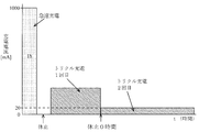
次に、図2を参照して、本実施形態の電気シェーバ1におけるトリクル充電方式について説明する。本電気シェーバ1におけるトリクル充電方式では、急速充電の終了後の第1回目のトリクル充電における充電電流の値と、第2回目以降のトリクル充電における充電電流の値とを異ならせている。具体的には、マイコン5は、第2回目以降のトリクル充電における充電電流の値(50mA)を、第1回目のトリクル充電における充電電流の値(100mA)よりも低い値にする。ここで、第1回目のトリクル充電における充電電流の値(100mA)は、不活性状態になったニッケル水素電池(以下、不活性電池と略す)を活性化させながら充電するために必要な電流値である。また、第2回目以降のトリクル充電における充電電流の値(50mA)は、電池の自然放電を補うために必要なトリクル充電電流の電流値である。
また、マイコン5は、図2に示されるように、急速充電と第1回目のトリクル充電との間には、充電の休止時間を挿入しない(急速充電後の休止時間は0時間に設定する)が、第1回目以降の各トリクル充電の間に、充電の休止時間を挿入する。具体的には、マイコン5は、スイッチング素子6を制御することにより、1000mAの電流値で1時間急速充電させた後、充電を休止せずに、第1回目のトリクル充電に移行する。そして、第1回目のトリクル充電において、100mAの電流値で8時間充電させた後、充電を3.5時間休止させる。この後、マイコン5は、第2回目以降の各トリクル充電における50mAの電流値による2.5時間の充電処理と、その後の3.5時間の充電の休止処理とを繰り返す。なお、上記の第1回目以降の各トリクル充電の間に挿入する休止時間は、電気シェーバ1の使用に影響しない範囲の時間(電気シェーバ1が自然放電やマイコン5による電力消費により使用できなくなるのを防ぐのに充分短い時間)に設定される。
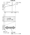
上記図2に示されるパターンのトリクル充電を行った場合には、充電対象となる二次電池3が不活性状態になっているときでも、満充電にすることができる。以下に、この点について、図3を参照して説明する。図3は、本電気シェーバ1において、通常の電池に充電した場合と、不活性電池に充電した場合における、急速充電とトリクル充電のパターンを示すグラフである。本電気シェーバ1も、特許文献1に示される従来の充電器と同様、上記図8に示されるように、電池電圧の値がピーク値を越えてピーク値より低い値になったときに急速充電を終了させる方式を採用している。このため、充電対象となる二次電池3が不活性電池の場合は、満充電になる前に急速充電を終了してしまうことが多い。従って、図3に示されるように、不活性電池に充電した場合は、通常の電池に充電した場合と比べて、急速充電の時間が短くなり、充電不足が生じることが多い。
上記の不活性電池で発生する充電不足への対策として、本電気シェーバ1のマイコン5は、図3の下段に示されるように、急速充電後の第1回目のトリクル充電において、不活性電池を活性化させながら充電するために必要な電流値(100mA)で8時間充電する。この第1回目のトリクル充電により、マイコン5は、不活性状態の二次電池3の活性化をさせつつ、図8中の両方向矢印で示される、急速充電で充電できなかった容量を補い、二次電池3を一旦満充電の状態まで充電する。その後、マイコン5は、図3の下段に示されるように、第2回目以降の各トリクル充電において、電池の自然放電を補うための充電を行う。上記のように、本電気シェーバ1では、第1回目のトリクル充電において、不活性電池を活性化させながら充電するために必要な電流値で充電したことにより、充電対象となる二次電池3が不活性状態になっているときでも、満充電にすることができる。
これに対して、充電対象となる二次電池3が通常の電池のときには、二次電池3は、急速充電でほぼ満充電の状態まで充電されてしまうので、第1回目のトリクル充電における充電の目的は、主に電池の自然放電を補うためになる。
次に、本電気シェーバ1において行われるトリクル充電のパターンの変形例について、図4乃至図7を参照して説明する。図4に示されるトリクル充電のパターンは、急速充電と第1回目のトリクル充電との間にも、充電の休止時間を挿入するという点で、図2に示されるトリクル充電のパターンと異なっている。それ以外の点については、図2に示されるトリクル充電のパターンと基本的に同じである。ただし、急速充電と第1回目のトリクル充電との間に休止時間を挿入したことにより生じる(自然放電による)残容量の不足を補うために、第1回目のトリクル充電の時間を、図2中の第1回目のトリクル充電の時間(8時間)よりも長くすることが望ましい。或いは、上記の残容量の不足を補うために、図4中の第1回目のトリクル充電の電流値を、図2中の第1回目のトリクル充電の電流値(100mA)より高くしてもよい。なお、上記の急速充電と第1回目のトリクル充電との間に挿入する休止時間は、二次電池3の活性化に影響しない範囲の時間(活性化に影響しない程度に短い時間)に設定される。
また、図5に示されるトリクル充電のパターンは、第1回目以降の各トリクル充電の間に充電の休止時間が挿入されていないという点で、図4に示されるトリクル充電のパターンと異なっている。それ以外の点については、図4に示されるトリクル充電のパターンと基本的に同じである。ただし、このトリクル充電のパターンでは、第1回目以降の各トリクル充電の間に充電の休止時間を挿入せず、第2回目のトリクル充電を継続して行うようにしたために、第2回目のトリクル充電の合計時間が増える。この第2回目のトリクル充電の合計時間の増加を考慮して、図5のトリクル充電のパターンでは、第2回目のトリクル充電の電流値(20mA)を、図4中の第2回目以降のトリクル充電の電流値(50mA)と比べて小さくしている。
さらにまた、図6に示されるトリクル充電のパターンは、第1回目以降の各トリクル充電の間に充電の休止時間が挿入されていないという点で、図2に示されるトリクル充電のパターンと異なっている。それ以外の点については、図2に示されるトリクル充電のパターンと基本的に同じである。ただし、このトリクル充電のパターンでは、第1回目以降の各トリクル充電の間に充電の休止時間を挿入せず、第2回目のトリクル充電を継続して行うようにしたために、第2回目のトリクル充電の合計時間が増える。この第2回目のトリクル充電の合計時間の増加を考慮して、図6のトリクル充電のパターンでは、第2回目のトリクル充電の電流値(20mA)を、図2中の第2回目以降のトリクル充電の電流値(50mA)と比べて小さくしている。
また、図7に示されるトリクル充電のパターンは、第2回目のトリクル充電の電流値(75mA)を、第3回目のトリクル充電の電流値(50mA)よりも高くしている点で、図4に示されるトリクル充電のパターンと異なっており、それ以外の点については、図4に示されるトリクル充電のパターンと基本的に同じである。なお、第4回目以降のトリクル充電の電流値については、第3回目のトリクル充電の電流値(50mA)よりも低くしてもよいし、第3回目のトリクル充電の電流値と同じであってもよい。
上述したように、本実施形態の電気シェーバ1によれば、急速充電の終了後の第1回目のトリクル充電における充電電流の値と、第2回目以降のトリクル充電における充電電流の値とを異ならせるようにした。すなわち、第2回目以降のトリクル充電における充電電流の値を、第1回目のトリクル充電における充電電流の値よりも低い値にした。より具体的には、第1回目のトリクル充電では、不活性電池を活性化させつつ充電するために必要な電流値の充電電流で充電を行い、第2回目以降のトリクル充電では、電池の自然放電を補うために必要な電流値の充電電流で充電を行うようにした。従って、第1回目のトリクル充電では、不活性電池を活性化させつつ充電することができる。また、第2回目以降のトリクル充電では、電池の自然放電を補うために必要な電流値の充電電流で充電を行うようにしたことにより、従来のように不活性電池を活性化させつつ充電するために必要な、一定の電流値でトリクル充電を継続した場合と比べて、充電に必要な消費電力を抑えることが可能になる。
また、本電気シェーバ1において行われるトリクル充電のパターンが、図2、図4、図5、及び図7のパターンの場合には、マイコン5は、急速充電と第1回目のトリクル充電との間、又は/及び第1回目以降の各トリクル充電の間に、充電の休止時間を挿入する。これにより、従来のように不活性電池を活性化させつつ充電するために必要な、一定の電流値でトリクル充電を継続した場合と比べて、充電に必要な消費電力をさらに抑えることが可能になる。
なお、本発明は、上記実施形態の構成に限られず、発明の趣旨を変更しない範囲で種々の変形が可能である。例えば、上記実施形態では、本発明の充電式電気機器が電気シェーバ1である場合の例について示したが、例えば携帯電話や携帯型の情報機器等の充電式電気機器に、本発明を適用してもよい。また、本発明の充電式電気機器が有する二次電池は、必ずしもニッケル水素電池に限られない。さらにまた、上記の実施形態では、スイッチング素子6がMOSFETである場合の例を示したが、スイッチング素子6は、バイポーラ型のトランジスタであってもよい。
本願は日本国特許出願2011-205027に基づいており、その内容は、上記特許出願の明細書及び図面を参照することによって結果的に本願発明に合体されるべきものである。また、本願発明は、添付した図面を参照した実施の形態により十分に記載されているけれども、さまざまな変更や変形が可能であることは、この分野の通常の知識を有するものにとって明らかであろう。それゆえ、そのような変更及び変形は、本願発明の範囲を逸脱するものではなく、本願発明の範囲に含まれると解釈されるべきである。
Claims (4)
- 充電可能な二次電池と、
前記二次電池と電源との間に設けられたスイッチング素子と、
時間を計測する時間計測手段を有し、この時間計測手段から出力された時間に基づいて、前記スイッチング素子のオンの時間とオフの時間との比率であるデューティ比を制御することにより、前記二次電池に充電する充電電流の値を制御する制御手段とを備えた充電式電気機器において、
前記二次電池への充電は、急速充電と、この急速充電の終了後の前記二次電池を、前記急速充電時の充電電流よりも小さな値の電流で充電するためのトリクル充電とを含み、
前記制御手段は、前記急速充電の終了後の第1回目のトリクル充電における充電電流の値と、第2回目以降のトリクル充電における充電電流の値とを異ならせることを特徴とする充電式電気機器。 - 前記制御手段は、前記急速充電と前記第1回目のトリクル充電との間、又は/及び前記第1回目以降の各トリクル充電の間に、充電の休止時間を挿入するようにしたことを特徴とする請求項1に記載の充電式電気機器。
- 前記制御手段は、前記第2回目以降のトリクル充電における充電電流の値を、前記第1回目のトリクル充電における充電電流の値よりも低い値にすることを特徴とする請求項2に記載の充電式電気機器。
- 前記制御手段は、前記第2回目以降のトリクル充電における充電電流の値を、前記第1回目のトリクル充電における充電電流の値よりも低い値にすることを特徴とする請求項1に記載の充電式電気機器。
Priority Applications (4)
| Application Number | Priority Date | Filing Date | Title |
|---|---|---|---|
| RU2014108214/07A RU2014108214A (ru) | 2011-09-20 | 2012-06-12 | Перезаряжаемое электрическое устройство |
| CN201280040621.1A CN103765724B (zh) | 2011-09-20 | 2012-06-12 | 充电式电设备 |
| US14/342,699 US9231417B2 (en) | 2011-09-20 | 2012-06-12 | Rechargeable electrical device |
| EP12833302.8A EP2760106A4 (en) | 2011-09-20 | 2012-06-12 | RECHARGEABLE ELECTRICAL DEVICE |
Applications Claiming Priority (2)
| Application Number | Priority Date | Filing Date | Title |
|---|---|---|---|
| JP2011205027A JP5919506B2 (ja) | 2011-09-20 | 2011-09-20 | 充電式電気機器 |
| JP2011-205027 | 2011-09-20 |
Publications (1)
| Publication Number | Publication Date |
|---|---|
| WO2013042293A1 true WO2013042293A1 (ja) | 2013-03-28 |
Family
ID=47914087
Family Applications (1)
| Application Number | Title | Priority Date | Filing Date |
|---|---|---|---|
| PCT/JP2012/003823 WO2013042293A1 (ja) | 2011-09-20 | 2012-06-12 | 充電式電気機器 |
Country Status (6)
| Country | Link |
|---|---|
| US (1) | US9231417B2 (ja) |
| EP (1) | EP2760106A4 (ja) |
| JP (1) | JP5919506B2 (ja) |
| CN (1) | CN103765724B (ja) |
| RU (1) | RU2014108214A (ja) |
| WO (1) | WO2013042293A1 (ja) |
Families Citing this family (9)
| Publication number | Priority date | Publication date | Assignee | Title |
|---|---|---|---|---|
| KR101428293B1 (ko) * | 2012-12-18 | 2014-08-07 | 현대자동차주식회사 | 전기자동차용 보조배터리의 주기적 충전 방법 |
| JP6214032B2 (ja) * | 2013-08-08 | 2017-10-18 | 東芝テック株式会社 | 充電制御装置及びプログラム |
| TW201607193A (zh) * | 2014-08-14 | 2016-02-16 | 菲利浦莫里斯製品股份有限公司 | 具有短路防止之可再充電裝置 |
| JP6308092B2 (ja) * | 2014-10-06 | 2018-04-11 | 株式会社デンソー | 電子制御装置 |
| KR102502450B1 (ko) * | 2015-11-02 | 2023-02-22 | 삼성전자주식회사 | 배터리 충전 방법 및 배터리 충전 장치 |
| CN106100018B (zh) * | 2016-06-13 | 2019-06-04 | Tcl移动通信科技(宁波)有限公司 | 一种基于移动终端的充电控制方法及系统 |
| EP3484010A4 (en) * | 2016-07-13 | 2020-01-08 | Sony Corporation | INFORMATION PROCESSING DEVICE, INFORMATION PROCESSING SYSTEM, AND CHARGING METHOD |
| KR102544462B1 (ko) * | 2018-01-25 | 2023-06-19 | 삼성전자 주식회사 | 배터리를 포함하는 전자 장치 및 이의 충전구간을 제어하는 방법 |
| TWI784788B (zh) * | 2021-11-10 | 2022-11-21 | 技嘉科技股份有限公司 | 供電調控電路、充電裝置與其供電模式調整方法 |
Citations (7)
| Publication number | Priority date | Publication date | Assignee | Title |
|---|---|---|---|---|
| JPS645334A (en) * | 1987-06-24 | 1989-01-10 | Matsushita Electric Works Ltd | Boosting charge control device |
| JPH01180145U (ja) * | 1988-06-06 | 1989-12-25 | ||
| JPH04244740A (ja) * | 1991-01-28 | 1992-09-01 | Matsushita Electric Works Ltd | 充電装置 |
| JPH05137271A (ja) * | 1991-11-08 | 1993-06-01 | Nec Corp | 電池充電方法 |
| JPH097643A (ja) * | 1995-06-16 | 1997-01-10 | Jitsupu Chiyaaji:Kk | 充電装置及び充電処理システム |
| JP2007259632A (ja) * | 2006-03-24 | 2007-10-04 | Nec Personal Products Co Ltd | 充電回路及び充電制御方法 |
| JP2009232669A (ja) * | 2008-02-29 | 2009-10-08 | Oki Electric Ind Co Ltd | バッテリバックアップ装置 |
Family Cites Families (14)
| Publication number | Priority date | Publication date | Assignee | Title |
|---|---|---|---|---|
| US5315228A (en) | 1992-01-24 | 1994-05-24 | Compaq Computer Corp. | Battery charge monitor and fuel gauge |
| JPH0614472A (ja) | 1992-06-24 | 1994-01-21 | Sanyo Electric Co Ltd | 充電器 |
| CA2098468C (en) | 1992-07-07 | 1998-09-01 | David J. Theobald | Method for battery charging |
| JP3499902B2 (ja) * | 1992-07-17 | 2004-02-23 | ペンタックス株式会社 | 二次電池充電装置 |
| US5539298A (en) * | 1993-03-19 | 1996-07-23 | Compaq Computer Corporation | Pulse charge technique to trickle charge a rechargeable battery |
| US5412306A (en) * | 1993-09-14 | 1995-05-02 | Motorola, Inc. | Method and apparatus for charging a battery |
| US6104165A (en) | 1995-06-16 | 2000-08-15 | Zip Charge Corporation | Multi-stage battery charging system |
| US5998968A (en) * | 1997-01-07 | 1999-12-07 | Ion Control Solutions, Llc | Method and apparatus for rapidly charging and reconditioning a battery |
| DE69942848D1 (de) | 1998-06-09 | 2010-11-25 | Makita Corp | Batterieladegerät |
| US6172480B1 (en) | 1998-10-23 | 2001-01-09 | Primetech Electronics, Inc. | Compact fast battery charger |
| US20010048287A1 (en) * | 2000-11-01 | 2001-12-06 | Jean-Pierre Vandelac | Compact fast battery charger |
| US7176654B2 (en) * | 2002-11-22 | 2007-02-13 | Milwaukee Electric Tool Corporation | Method and system of charging multi-cell lithium-based batteries |
| JP5020530B2 (ja) * | 2006-04-14 | 2012-09-05 | パナソニック株式会社 | 充電方法ならびに電池パックおよびその充電器 |
| CN101546919B (zh) * | 2009-01-21 | 2011-08-24 | 炬力集成电路设计有限公司 | 一种电池充电方法及装置 |
-
2011
- 2011-09-20 JP JP2011205027A patent/JP5919506B2/ja active Active
-
2012
- 2012-06-12 EP EP12833302.8A patent/EP2760106A4/en not_active Withdrawn
- 2012-06-12 RU RU2014108214/07A patent/RU2014108214A/ru not_active Application Discontinuation
- 2012-06-12 CN CN201280040621.1A patent/CN103765724B/zh active Active
- 2012-06-12 US US14/342,699 patent/US9231417B2/en active Active
- 2012-06-12 WO PCT/JP2012/003823 patent/WO2013042293A1/ja active Application Filing
Patent Citations (7)
| Publication number | Priority date | Publication date | Assignee | Title |
|---|---|---|---|---|
| JPS645334A (en) * | 1987-06-24 | 1989-01-10 | Matsushita Electric Works Ltd | Boosting charge control device |
| JPH01180145U (ja) * | 1988-06-06 | 1989-12-25 | ||
| JPH04244740A (ja) * | 1991-01-28 | 1992-09-01 | Matsushita Electric Works Ltd | 充電装置 |
| JPH05137271A (ja) * | 1991-11-08 | 1993-06-01 | Nec Corp | 電池充電方法 |
| JPH097643A (ja) * | 1995-06-16 | 1997-01-10 | Jitsupu Chiyaaji:Kk | 充電装置及び充電処理システム |
| JP2007259632A (ja) * | 2006-03-24 | 2007-10-04 | Nec Personal Products Co Ltd | 充電回路及び充電制御方法 |
| JP2009232669A (ja) * | 2008-02-29 | 2009-10-08 | Oki Electric Ind Co Ltd | バッテリバックアップ装置 |
Non-Patent Citations (1)
| Title |
|---|
| See also references of EP2760106A4 * |
Also Published As
| Publication number | Publication date |
|---|---|
| CN103765724A (zh) | 2014-04-30 |
| EP2760106A1 (en) | 2014-07-30 |
| JP2013070442A (ja) | 2013-04-18 |
| EP2760106A4 (en) | 2015-09-16 |
| US9231417B2 (en) | 2016-01-05 |
| JP5919506B2 (ja) | 2016-05-18 |
| RU2014108214A (ru) | 2015-10-27 |
| US20140225573A1 (en) | 2014-08-14 |
| CN103765724B (zh) | 2016-04-13 |
Similar Documents
| Publication | Publication Date | Title |
|---|---|---|
| WO2013042293A1 (ja) | 充電式電気機器 | |
| US7863865B2 (en) | Systems and methods for pulse charging a battery | |
| CN107894567B (zh) | 电池包以及电池包接口状态的检测系统和检测方法 | |
| JP6017517B2 (ja) | 家庭用装置の電池充電器 | |
| TWI751229B (zh) | 控制裝置、控制系統、蓄電裝置以及電腦可讀取媒體 | |
| US20140360512A1 (en) | Charging method of electronic cigarettes and electronic cigarette box | |
| EP3007306A1 (en) | Electronic cigarette charging method and electronic cigarette case | |
| US9118198B2 (en) | Balancing of battery cells connected in parallel | |
| JP5892370B2 (ja) | 充電器及び電力供給システム | |
| JP2009225632A (ja) | 充電制御回路、電池パック、及び充電システム | |
| KR20120113165A (ko) | 충전전류를 제어하는 방법 | |
| CN103503272A (zh) | 供电设备、逆变设备和电动工具 | |
| US8093865B2 (en) | Charging device with backflow prevention | |
| US20160308376A1 (en) | Energy storage system | |
| JP6931086B2 (ja) | 二次電池を充電するための電気回路及び方法 | |
| US9509150B2 (en) | Charging circuit and control method therefor | |
| KR101818694B1 (ko) | 부하 결합 변경을 이용한 급속충전장치 | |
| JP5796216B2 (ja) | 電源装置 | |
| JP2003169424A (ja) | 二次電池の充電方法、充電装置 | |
| JP2011239578A (ja) | 充電装置及び充電方法 | |
| JP2010288403A (ja) | 組電池充電制御装置 | |
| US20040177282A1 (en) | Method and circuit for controlling battery charge and supply by microprocessor | |
| JP5454070B2 (ja) | 充電式電池装置 | |
| CN211180588U (zh) | 应用于洁面工具的控制电路 | |
| JP2012055043A (ja) | 充電システム、電池パック及び充電器 |
Legal Events
| Date | Code | Title | Description |
|---|---|---|---|
| 121 | Ep: the epo has been informed by wipo that ep was designated in this application |
Ref document number: 12833302 Country of ref document: EP Kind code of ref document: A1 |
|
| WWE | Wipo information: entry into national phase |
Ref document number: 14342699 Country of ref document: US |
|
| NENP | Non-entry into the national phase |
Ref country code: DE |
|
| ENP | Entry into the national phase |
Ref document number: 2014108214 Country of ref document: RU Kind code of ref document: A |