WO2013042293A1 - Dispositif électrique rechargeable - Google Patents
Dispositif électrique rechargeable Download PDFInfo
- Publication number
- WO2013042293A1 WO2013042293A1 PCT/JP2012/003823 JP2012003823W WO2013042293A1 WO 2013042293 A1 WO2013042293 A1 WO 2013042293A1 JP 2012003823 W JP2012003823 W JP 2012003823W WO 2013042293 A1 WO2013042293 A1 WO 2013042293A1
- Authority
- WO
- WIPO (PCT)
- Prior art keywords
- charge
- charging
- trickle
- value
- current
- Prior art date
Links
Images


Classifications
-
- H—ELECTRICITY
- H02—GENERATION; CONVERSION OR DISTRIBUTION OF ELECTRIC POWER
- H02J—CIRCUIT ARRANGEMENTS OR SYSTEMS FOR SUPPLYING OR DISTRIBUTING ELECTRIC POWER; SYSTEMS FOR STORING ELECTRIC ENERGY
- H02J7/00—Circuit arrangements for charging or depolarising batteries or for supplying loads from batteries
- H02J7/02—Circuit arrangements for charging or depolarising batteries or for supplying loads from batteries for charging batteries from ac mains by converters
- H02J7/04—Regulation of charging current or voltage
-
- H—ELECTRICITY
- H01—ELECTRIC ELEMENTS
- H01M—PROCESSES OR MEANS, e.g. BATTERIES, FOR THE DIRECT CONVERSION OF CHEMICAL ENERGY INTO ELECTRICAL ENERGY
- H01M10/00—Secondary cells; Manufacture thereof
- H01M10/42—Methods or arrangements for servicing or maintenance of secondary cells or secondary half-cells
- H01M10/44—Methods for charging or discharging
- H01M10/448—End of discharge regulating measures
-
- H—ELECTRICITY
- H02—GENERATION; CONVERSION OR DISTRIBUTION OF ELECTRIC POWER
- H02J—CIRCUIT ARRANGEMENTS OR SYSTEMS FOR SUPPLYING OR DISTRIBUTING ELECTRIC POWER; SYSTEMS FOR STORING ELECTRIC ENERGY
- H02J7/00—Circuit arrangements for charging or depolarising batteries or for supplying loads from batteries
- H02J7/0029—Circuit arrangements for charging or depolarising batteries or for supplying loads from batteries with safety or protection devices or circuits
- H02J7/00304—Overcurrent protection
-
- H—ELECTRICITY
- H02—GENERATION; CONVERSION OR DISTRIBUTION OF ELECTRIC POWER
- H02J—CIRCUIT ARRANGEMENTS OR SYSTEMS FOR SUPPLYING OR DISTRIBUTING ELECTRIC POWER; SYSTEMS FOR STORING ELECTRIC ENERGY
- H02J7/00—Circuit arrangements for charging or depolarising batteries or for supplying loads from batteries
- H02J7/007—Regulation of charging or discharging current or voltage
-
- H—ELECTRICITY
- H01—ELECTRIC ELEMENTS
- H01M—PROCESSES OR MEANS, e.g. BATTERIES, FOR THE DIRECT CONVERSION OF CHEMICAL ENERGY INTO ELECTRICAL ENERGY
- H01M2220/00—Batteries for particular applications
- H01M2220/30—Batteries in portable systems, e.g. mobile phone, laptop
-
- H—ELECTRICITY
- H02—GENERATION; CONVERSION OR DISTRIBUTION OF ELECTRIC POWER
- H02J—CIRCUIT ARRANGEMENTS OR SYSTEMS FOR SUPPLYING OR DISTRIBUTING ELECTRIC POWER; SYSTEMS FOR STORING ELECTRIC ENERGY
- H02J7/00—Circuit arrangements for charging or depolarising batteries or for supplying loads from batteries
- H02J7/0029—Circuit arrangements for charging or depolarising batteries or for supplying loads from batteries with safety or protection devices or circuits
- H02J7/00302—Overcharge protection
-
- Y—GENERAL TAGGING OF NEW TECHNOLOGICAL DEVELOPMENTS; GENERAL TAGGING OF CROSS-SECTIONAL TECHNOLOGIES SPANNING OVER SEVERAL SECTIONS OF THE IPC; TECHNICAL SUBJECTS COVERED BY FORMER USPC CROSS-REFERENCE ART COLLECTIONS [XRACs] AND DIGESTS
- Y02—TECHNOLOGIES OR APPLICATIONS FOR MITIGATION OR ADAPTATION AGAINST CLIMATE CHANGE
- Y02E—REDUCTION OF GREENHOUSE GAS [GHG] EMISSIONS, RELATED TO ENERGY GENERATION, TRANSMISSION OR DISTRIBUTION
- Y02E60/00—Enabling technologies; Technologies with a potential or indirect contribution to GHG emissions mitigation
- Y02E60/10—Energy storage using batteries
Definitions
- the present invention relates to a rechargeable electric device capable of rapidly charging a built-in secondary battery, and more particularly to a rechargeable electric device having a trickle charge function.
- Ni-MH nickel-metal hydride batteries
- the charge function in rechargeable electric devices has also evolved, and quick charging with a larger charging current than conventional charging current completes charging in a shorter time than conventional rechargeable electric devices
- the number of rechargeable electrical devices is increasing significantly.
- the charging current at the time of rapid charging is to compensate for the natural discharge of the battery even after rapid charging and to activate the inactive battery.
- Charging was continued with a minute current having a constant current value smaller than the value. Charging with a minute current having a constant current value is referred to as trickle charging.
- the microcomputer has a function (remaining capacity detection function) for detecting the remaining capacity of the secondary battery, and the microcomputer has 100% remaining capacity (full charge). There are many cases where the charging of the secondary battery is terminated when it is detected.
- the microcomputer is always started, and at least the charge current amount charged to the secondary battery and the secondary battery discharged to the load Since it is necessary to manage the amount of discharge current, power consumption by the microcomputer becomes a problem.
- Ni-MH Nickel metal hydride
- a nickel metal hydride battery As a secondary battery is almost fully charged when the battery voltage value exceeds the peak value and becomes lower than the peak value during charging. It has the characteristic of becoming a state.
- the microcomputer detects that the value of the battery voltage exceeds the peak value and becomes lower than the peak value, it is fully charged. It has been determined that the rapid charging has ended, and it has been increased (see Patent Document 1).
- this rechargeable electric device unlike the above-described conventional rechargeable electric device having a remaining capacity detection function, there is no need to constantly activate the microcomputer to manage the amount of charging current and the amount of discharging current. It is possible to reduce power consumption.
- the nickel hydrogen battery hereinafter referred to Active batteries can not be fully charged only by rapid charging.
- the conventional device of this type continuously carries out trickle charge after rapid charging, thereby activating the inactive battery and performing bidirectional activation in the diagram.
- the secondary battery was charged to a fully charged state by compensating for the capacity that could not be charged by quick charging, as indicated by the arrows.
- the current value of the trickle charge current necessary to activate (while charging) the inactive battery is larger than the current value of the trickle charge current necessary to compensate for the natural discharge of the battery. Therefore, once the inactive battery is activated and charged to the fully charged state, it should be possible to perform trickle charge with a charge current of a smaller value than before. Nevertheless, in the case of rechargeable electric equipment that continues trickle charge after conventional quick charge, the trickle charge current of constant current value necessary for activating and charging inactive battery after quick charge The power consumption is wasted because the
- the present invention solves the above-mentioned problems, and in trickle charging, a rechargeable electric device capable of charging while activating an inactive battery and capable of suppressing power consumption necessary for charging. Intended to be provided.
- a rechargeable electric device comprises a rechargeable secondary battery, a switching element provided between the secondary battery and a power supply, and a time measuring means for measuring time.
- the charging current for charging the secondary battery by controlling the duty ratio which is the ratio of the on time and the off time of the switching element based on the time output from the time measuring means.
- the charging to the secondary battery is performed by a rapid charging and a charging current at the time of the rapid charging of the secondary battery after the termination of the rapid charging.
- trickle charge for charging with a small current and the control means is configured to charge current in the first trickle charge after the end of the rapid charge and charge in the second and subsequent trickle charges. And wherein varying the value of the current.
- the value of the charge current in the first trickle charge after the end of the rapid charge and the value of the charge current in the second and subsequent trickle charges are made different.
- charging is performed with a charging current of a current value necessary to activate and charge the inactive battery
- the second and subsequent trickle charges the battery is naturally discharged.
- Charging can be performed with a charging current of a current value necessary to compensate for Therefore, in the first trickle charge, charging can be performed while activating the inactive battery.
- charging is performed while activating the inactive battery as in the prior art by charging with a charging current of a current value necessary to compensate for the natural discharge of the battery. Power consumption required for charging can be reduced as compared with the case where trickle charging is continued at a constant current value necessary for
- the control means inserts a charging pause time between the quick charge and the first trickle charge or / and between the first and subsequent trickle charges. May be
- control means sets the value of the charging current in the second and subsequent trickle charges to a value lower than the value of the charging current in the first trickle charge.
- the circuit block diagram of the electric shaver which is a charge-type electric equipment which concerns on one Embodiment of this invention, and an adapter.
- the electric shaver WHEREIN The graph which shows the pattern of a rapid charge and a trickle charge in the case where an ordinary battery is charged, and the case where an inactive battery is charged.
- FIG. 1 shows a circuit configuration of an electric shaver 1 of the present embodiment (a rechargeable electric device in the claims) and an adapter 11 connected to the electric shaver 1 at the time of charging.
- the electric shaver 1 is a chargeable electric shaver, and is a load terminal motor 2, a rechargeable secondary battery 3 for supplying power to the motor 2, and a charging terminal electrically connected to the secondary battery 3. 4a and 4b are provided.
- the secondary battery 3 is configured by connecting in series a plurality of nickel hydrogen batteries having a standard battery voltage value of 1.4V.
- the electric shaver 1 includes a microcomputer 5 (control means) for controlling the entire apparatus and a switching element 6.
- the microcomputer 5 has a timer 8 (time measuring means) for measuring time, and based on the time output from the timer 8, a duty ratio which is a ratio of the on time of the switching element 6 to the off time is By controlling, the value of the charging current for charging the secondary battery 3 is controlled. Further, the microcomputer 5 keeps the switching element 6 in the off state for a predetermined time based on the time output from the timer 8 to thereby perform the quick charge and the first trickle charge after the quick charge. And / or between the first and subsequent trickle charges after the quick charge, charging pause time may be inserted.
- the switching element 6 is an n-channel enhancement type MOSFET (Metal Oxide Semiconductor Field Effect Transistor).
- the switching element 6 is provided between the secondary battery 3 and the adapter 11 (that is, between the secondary battery 3 and the commercial power supply 20).
- Switching element 6 cuts off a path connecting charging terminal 4a to the + side of secondary battery 3 in accordance with high / low of the voltage level of the control signal input to the gate from microcomputer 5 via line L5 (see FIG. Switch between off) and connection (on). Specifically, when the voltage level of the control signal input to the gate of switching element 6 is high, the drain and source of switching element 6 conduct, and charging terminal 4 a and the positive side of secondary battery 3 The connecting path is connected to charge the secondary battery 3.
- MOSFET Metal Oxide Semiconductor Field Effect Transistor
- Lines L0 to L5 are connected to a plurality of input / output terminals (not shown) of the microcomputer 5, respectively.
- the line L0 is an input line for detecting a charging current value to the secondary battery 3.
- the microcomputer 5 flows the current input to the line L0 to the resistor provided inside the microcomputer, measures the value of voltage drop due to this resistance, and charges the secondary battery 3 based on the value of the voltage drop. Detect (determine) the current value.
- the line L1 is an input line for detecting the voltage value on the positive side of the secondary battery 3.
- a ground line (hereinafter, referred to as a GND line) L2 is an input line for detecting a voltage value on the negative side of the secondary battery 3.
- the microcomputer 5 detects the value of the battery voltage of the secondary battery 3 based on the voltage applied to the line L1 and the voltage applied to the GND line L2.
- Line L3 is an input line for power supply that connects the secondary battery 3 and the microcomputer 5. Furthermore, the line L4 is an input line for detecting a discharge current value discharged from the secondary battery 3 to the motor 2.
- the microcomputer 5 flows the current input to the line L4 to a resistor provided inside the microcomputer, measures the value of the voltage drop due to this resistance, and based on the value of the voltage drop, the discharge current value to the motor 2 To detect (determine) Then, the microcomputer 5 prevents an overcurrent from flowing to the motor 2 which is a load, based on the detected discharge current value.
- the line L5 is an output line of a control signal for switching connection and disconnection of a (charging) path connecting the charging terminal 4a and the + side of the secondary battery 3.
- the microcomputer 5 adjusts (changes) the duty ratio which is the ratio of the on time and the off time of the switching element 6 according to the level of the charging current detected based on the current input to the line L0.
- the value of the charging current for charging the secondary battery 3 is feedback controlled.
- the electric shaver 1 further includes an operation switch 7. At the time of use of the electric shaver 1, when the operation switch 7 is turned on by the user and short-circuited, the secondary battery 3 and the motor 2 are electrically connected, and power from the secondary battery 3 to the motor 2 is supplied. Is supplied to drive the motor 2.
- the adapter 11 is a switching power supply that converts AC power (voltage) of the commercial power supply 20 into DC power (voltage) and supplies power (power) to the electric shaver 1.
- the adapter 11 has connection terminals 12 a and 12 b for connection to the commercial power supply 20, and power supply terminals 17 a and 17 b for connection (with power supply) to the electric shaver 1.
- the adapter 11 When charging the secondary battery 3, the adapter 11 has the connection terminals 12 a and 12 b connected to the commercial power supply 20, and the power supply terminals 17 a and 17 b connected to the electric shaver 1 to supply AC power supplied from the commercial power supply 20. Supply DC power to the electric shaver 1.
- the adapter 11 smoothes the DC voltage of the pulsating current output from the diode bridge 13 and the diode bridge 13 for converting the AC voltage input from the commercial power supply 20 into the DC voltage of the pulsating current, and the voltage is substantially constant. And a smoothing capacitor C1 for converting into a direct current voltage.
- the adapter 11 further includes a control circuit 14 that controls the entire adapter and a step-down circuit 15 that steps down a DC voltage supplied via the smoothing capacitor C1.
- the control circuit 14 operates based on the power of the DC voltage supplied via the diode bridge 13 and the smoothing capacitor C1.
- the step-down circuit 15 includes a step-down transformer 18 and a transistor 16 for switching between application and non-application of voltage to the primary coil of the transformer 18.
- the transistor 16 is an NPN type bipolar transistor.
- the control circuit 14 switches between conduction (ON) and non-conduction (OFF) between the collector and emitter of the transistor 16 by switching high / low of the voltage level applied to the base of the transistor 16 through the output line L7. .
- the control circuit 14 switches between application and non-application of voltage to the primary coil of the transformer 18 by switching between conduction and non-conduction between the collector and emitter of the transistor 16.
- the control circuit 14 controls the ratio of the high time to the low time of the voltage level applied to the base of the transistor 16 so that the time of conduction (ON) between the collector and the emitter (OFF) Control the ratio to the time (so-called duty ratio).
- the control circuit 14 controls the voltage of the power output from the secondary coil of the transformer 18 to a substantially constant value.
- the adapter 11 also has a transformer 19 for detecting the voltage level induced in the secondary coil of the transformer 18.
- the control circuit 14 detects the value of the voltage induced in the transformer 19 through the input line L8 and the GND line L9, and based on the detected voltage value of the transformer 19, the voltage applied to the base of the transistor 16 Feedback control is performed on the duty ratio.
- the adapter 11 receives the pulse-like power output from the secondary coil of the transformer 18, and the diode D1 for backflow prevention and the smoothing capacitor for smoothing the voltage value of the power output from the diode D1. It is further equipped with C2.
- the trickle charging method in the electric shaver 1 of the present embodiment will be described.
- the microcomputer 5 sets the value (50 mA) of the charging current in the second and subsequent trickle charges to a value lower than the value (100 mA) of the charging current in the first trickle charge.
- the value (100 mA) of the charging current in the first trickle charge is the current value necessary for charging while activating the nickel hydrogen battery (hereinafter referred to as inactive battery) in the inactive state. It is.
- the value (50 mA) of the charging current in the second and subsequent trickle charging is a current value of the trickle charging current necessary to compensate for the natural discharge of the battery.
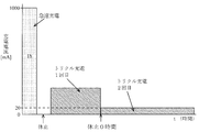
- the microcomputer 5 does not insert a charging pause time between the quick charge and the first trickle charge (the pause time after the quick charge is set to 0 hours). However, the pause time of charge is inserted between the first and subsequent trickle charges. Specifically, the microcomputer 5 controls the switching element 6 to rapidly charge the battery at a current value of 1000 mA for 1 hour, and then shifts to the first trickle charge without stopping the charge. Then, in the first trickle charge, after charging for 8 hours at a current value of 100 mA, charging is paused for 3.5 hours.
- the microcomputer 5 repeats the 2.5-hour charging process with the current value of 50 mA in each of the second and subsequent trickle charges and the 3.5-hour charging suspension process thereafter. Note that the pause time inserted between the first and subsequent trickle charges does not affect the use of the electric shaver 1 (the electric shaver 1 can not be used due to natural discharge or power consumption by the microcomputer 5). (Short enough time to prevent).
- FIG. 3 is a graph showing patterns of quick charge and trickle charge in the case of charging an ordinary battery and in the case of charging an inactive battery in the electric shaver 1.
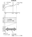
- the electric shaver 1 also rapidly charges when the value of the battery voltage exceeds the peak value and becomes lower than the peak value, as shown in FIG.
- the microcomputer 5 of the electric shaver 1 is, as shown in the lower part of FIG. Charge for 8 hours with the current value (100 mA) required to charge while activating.
- the microcomputer 5 activates the inactive secondary battery 3 and compensates for the capacity which can not be charged by the quick charge, as indicated by the double-headed arrow in FIG.
- the secondary battery 3 is once charged to a fully charged state.
- the microcomputer 5 performs charging for compensating for the natural discharge of the battery in each of the second and subsequent trickle charges.
- the secondary battery 3 to be charged is charged by charging with the current value necessary for charging while activating the inactive battery. Even when inactive, it can be fully charged.
- the secondary battery 3 to be charged is a normal battery
- the secondary battery 3 is charged to a nearly fully charged state by quick charging, so that charging of the first trickle charge
- the purpose is mainly to compensate for the natural discharge of the battery.
- the pattern of the trickle charge shown in FIG. 4 is different from the pattern of the trickle charge shown in FIG. 2 in that a pause time for charging is inserted also between the quick charge and the first trickle charge. .
- the other points are basically the same as the trickle charge pattern shown in FIG.
- the time of the first trickle charge is shown in FIG. It is desirable to make it longer than the first trickle charge time (8 hours).
- the pause time inserted between the above-mentioned quick charge and the first trickle charge is set to a time that does not affect activation of secondary battery 3 (a time short enough not to affect activation). Ru.
- the trickle charge pattern shown in FIG. 5 is different from the trickle charge pattern shown in FIG. 4 in that no charging rest time is inserted between the first and subsequent trickle charges. .
- the other points are basically the same as the trickle charge pattern shown in FIG.
- the second trickle charge is performed by continuing the second trickle charge without inserting the charging pause time between the first and subsequent trickle charges. Total time for charging increases.
- the current value (20 mA) of the second trickle charge is set to the second and subsequent trickle charges in FIG. It is smaller than the charging current value (50 mA).
- the trickle charge pattern shown in FIG. 6 is different from the trickle charge pattern shown in FIG. 2 in that no charging rest time is inserted between the first and subsequent trickle charges. There is.
- the other points are basically the same as the trickle charge pattern shown in FIG.
- the second trickle charge is performed by continuing the second trickle charge without inserting the charging pause time between the first and subsequent trickle charges. Total time for charging increases.
- the current value (20 mA) of the second trickle charge is set to the second and subsequent trickle charges in FIG. It is smaller than the charging current value (50 mA).
- the trickle charge pattern shown in FIG. 7 is that the current value (75 mA) of the second trickle charge is higher than the current value (50 mA) of the third trickle charge.
- the other points are basically the same as the trickle charge pattern shown in FIG.
- the fourth and subsequent trickle charge current values may be lower than the third trickle charge current value (50 mA), and the same as the third trickle charge current value. It is also good.
- the value of the charging current in the second and subsequent trickle charges is set to a value lower than the value of the charging current in the first trickle charge. More specifically, in the first trickle charge, charging is performed with a charge current of a current value necessary to activate and charge the inactive battery, and in the second and subsequent trickle charges, the battery is naturally It was made to charge by the charge current of the electric current value required to supplement discharge. Therefore, in the first trickle charge, charging can be performed while activating the inactive battery.
- the microcomputer 5 is between the quick charge and the first trickle charge. And / or between the first and subsequent trickle charges, a charging pause time is inserted. This makes it possible to further reduce the power consumption necessary for charging, as compared to the case where trickle charging is continued at a constant current value, which is necessary for charging while activating an inactive battery as in the prior art. Become.
- the present invention is not limited to the configuration of the above embodiment, and various modifications can be made without departing from the scope of the invention.
- the rechargeable electric device of the present invention is the electric shaver 1
- the present invention is applied to a rechargeable electric device such as a mobile phone or a portable information device.
- the secondary battery included in the rechargeable electric device of the present invention is not necessarily limited to the nickel hydrogen battery.
- the switching element 6 is a MOSFET is shown, but the switching element 6 may be a bipolar transistor.
Abstract
La valeur du courant de chargement, pour un premier chargement de maintien après achèvement d'un chargement rapide, diffère de la valeur du courant de chargement pour les chargements de maintien lors de la seconde fois et par la suite. Il est ainsi possible, par exemple, que, dans le premier chargement de maintien, le chargement se fasse avec un courant de chargement dont la valeur de courant est nécessaire pour le chargement tout en activant un accumulateur inactivé et, dans les chargements de maintien suivants, le chargement se fasse avec un courant de chargement ayant une valeur nécessaire pour compenser le déchargement naturel d'un accumulateur. Du fait que, dans les chargements de maintien suivants, le chargement s'effectue avec un courant de chargement ayant une valeur de courant qui est nécessaire pour compenser le déchargement naturel de l'accumulateur, il est possible de supprimer la consommation d'énergie nécessaire pour le chargement par rapport à une situation conventionnelle dans laquelle le chargement de maintien se poursuit avec une valeur de courant constante qui est nécessaire pour le chargement pendant l'activation d'un accumulateur inactivé.
Priority Applications (4)
| Application Number | Priority Date | Filing Date | Title |
|---|---|---|---|
| US14/342,699 US9231417B2 (en) | 2011-09-20 | 2012-06-12 | Rechargeable electrical device |
| RU2014108214/07A RU2014108214A (ru) | 2011-09-20 | 2012-06-12 | Перезаряжаемое электрическое устройство |
| EP12833302.8A EP2760106A4 (fr) | 2011-09-20 | 2012-06-12 | Dispositif électrique rechargeable |
| CN201280040621.1A CN103765724B (zh) | 2011-09-20 | 2012-06-12 | 充电式电设备 |
Applications Claiming Priority (2)
| Application Number | Priority Date | Filing Date | Title |
|---|---|---|---|
| JP2011-205027 | 2011-09-20 | ||
| JP2011205027A JP5919506B2 (ja) | 2011-09-20 | 2011-09-20 | 充電式電気機器 |
Publications (1)
| Publication Number | Publication Date |
|---|---|
| WO2013042293A1 true WO2013042293A1 (fr) | 2013-03-28 |
Family
ID=47914087
Family Applications (1)
| Application Number | Title | Priority Date | Filing Date |
|---|---|---|---|
| PCT/JP2012/003823 WO2013042293A1 (fr) | 2011-09-20 | 2012-06-12 | Dispositif électrique rechargeable |
Country Status (6)
| Country | Link |
|---|---|
| US (1) | US9231417B2 (fr) |
| EP (1) | EP2760106A4 (fr) |
| JP (1) | JP5919506B2 (fr) |
| CN (1) | CN103765724B (fr) |
| RU (1) | RU2014108214A (fr) |
| WO (1) | WO2013042293A1 (fr) |
Families Citing this family (9)
| Publication number | Priority date | Publication date | Assignee | Title |
|---|---|---|---|---|
| KR101428293B1 (ko) * | 2012-12-18 | 2014-08-07 | 현대자동차주식회사 | 전기자동차용 보조배터리의 주기적 충전 방법 |
| JP6214032B2 (ja) * | 2013-08-08 | 2017-10-18 | 東芝テック株式会社 | 充電制御装置及びプログラム |
| TW201607193A (zh) * | 2014-08-14 | 2016-02-16 | 菲利浦莫里斯製品股份有限公司 | 具有短路防止之可再充電裝置 |
| JP6308092B2 (ja) * | 2014-10-06 | 2018-04-11 | 株式会社デンソー | 電子制御装置 |
| KR102502450B1 (ko) * | 2015-11-02 | 2023-02-22 | 삼성전자주식회사 | 배터리 충전 방법 및 배터리 충전 장치 |
| CN106100018B (zh) * | 2016-06-13 | 2019-06-04 | Tcl移动通信科技(宁波)有限公司 | 一种基于移动终端的充电控制方法及系统 |
| US11336107B2 (en) * | 2016-07-13 | 2022-05-17 | Sony Corporation | Information processing device, information processing system, and charging method |
| KR102544462B1 (ko) | 2018-01-25 | 2023-06-19 | 삼성전자 주식회사 | 배터리를 포함하는 전자 장치 및 이의 충전구간을 제어하는 방법 |
| TWI784788B (zh) * | 2021-11-10 | 2022-11-21 | 技嘉科技股份有限公司 | 供電調控電路、充電裝置與其供電模式調整方法 |
Citations (7)
| Publication number | Priority date | Publication date | Assignee | Title |
|---|---|---|---|---|
| JPS645334A (en) * | 1987-06-24 | 1989-01-10 | Matsushita Electric Works Ltd | Boosting charge control device |
| JPH01180145U (fr) * | 1988-06-06 | 1989-12-25 | ||
| JPH04244740A (ja) * | 1991-01-28 | 1992-09-01 | Matsushita Electric Works Ltd | 充電装置 |
| JPH05137271A (ja) * | 1991-11-08 | 1993-06-01 | Nec Corp | 電池充電方法 |
| JPH097643A (ja) * | 1995-06-16 | 1997-01-10 | Jitsupu Chiyaaji:Kk | 充電装置及び充電処理システム |
| JP2007259632A (ja) * | 2006-03-24 | 2007-10-04 | Nec Personal Products Co Ltd | 充電回路及び充電制御方法 |
| JP2009232669A (ja) * | 2008-02-29 | 2009-10-08 | Oki Electric Ind Co Ltd | バッテリバックアップ装置 |
Family Cites Families (14)
| Publication number | Priority date | Publication date | Assignee | Title |
|---|---|---|---|---|
| US5315228A (en) * | 1992-01-24 | 1994-05-24 | Compaq Computer Corp. | Battery charge monitor and fuel gauge |
| JPH0614472A (ja) | 1992-06-24 | 1994-01-21 | Sanyo Electric Co Ltd | 充電器 |
| CA2098468C (fr) | 1992-07-07 | 1998-09-01 | David J. Theobald | Methode de charge d'une batterie |
| JP3499902B2 (ja) * | 1992-07-17 | 2004-02-23 | ペンタックス株式会社 | 二次電池充電装置 |
| US5539298A (en) * | 1993-03-19 | 1996-07-23 | Compaq Computer Corporation | Pulse charge technique to trickle charge a rechargeable battery |
| US5412306A (en) * | 1993-09-14 | 1995-05-02 | Motorola, Inc. | Method and apparatus for charging a battery |
| US6104165A (en) | 1995-06-16 | 2000-08-15 | Zip Charge Corporation | Multi-stage battery charging system |
| US5998968A (en) * | 1997-01-07 | 1999-12-07 | Ion Control Solutions, Llc | Method and apparatus for rapidly charging and reconditioning a battery |
| DE69942848D1 (de) * | 1998-06-09 | 2010-11-25 | Makita Corp | Batterieladegerät |
| US6172480B1 (en) * | 1998-10-23 | 2001-01-09 | Primetech Electronics, Inc. | Compact fast battery charger |
| US20010048287A1 (en) * | 2000-11-01 | 2001-12-06 | Jean-Pierre Vandelac | Compact fast battery charger |
| US7176654B2 (en) * | 2002-11-22 | 2007-02-13 | Milwaukee Electric Tool Corporation | Method and system of charging multi-cell lithium-based batteries |
| JP5020530B2 (ja) * | 2006-04-14 | 2012-09-05 | パナソニック株式会社 | 充電方法ならびに電池パックおよびその充電器 |
| CN101546919B (zh) * | 2009-01-21 | 2011-08-24 | 炬力集成电路设计有限公司 | 一种电池充电方法及装置 |
-
2011
- 2011-09-20 JP JP2011205027A patent/JP5919506B2/ja active Active
-
2012
- 2012-06-12 CN CN201280040621.1A patent/CN103765724B/zh active Active
- 2012-06-12 EP EP12833302.8A patent/EP2760106A4/fr not_active Withdrawn
- 2012-06-12 RU RU2014108214/07A patent/RU2014108214A/ru not_active Application Discontinuation
- 2012-06-12 WO PCT/JP2012/003823 patent/WO2013042293A1/fr active Application Filing
- 2012-06-12 US US14/342,699 patent/US9231417B2/en active Active
Patent Citations (7)
| Publication number | Priority date | Publication date | Assignee | Title |
|---|---|---|---|---|
| JPS645334A (en) * | 1987-06-24 | 1989-01-10 | Matsushita Electric Works Ltd | Boosting charge control device |
| JPH01180145U (fr) * | 1988-06-06 | 1989-12-25 | ||
| JPH04244740A (ja) * | 1991-01-28 | 1992-09-01 | Matsushita Electric Works Ltd | 充電装置 |
| JPH05137271A (ja) * | 1991-11-08 | 1993-06-01 | Nec Corp | 電池充電方法 |
| JPH097643A (ja) * | 1995-06-16 | 1997-01-10 | Jitsupu Chiyaaji:Kk | 充電装置及び充電処理システム |
| JP2007259632A (ja) * | 2006-03-24 | 2007-10-04 | Nec Personal Products Co Ltd | 充電回路及び充電制御方法 |
| JP2009232669A (ja) * | 2008-02-29 | 2009-10-08 | Oki Electric Ind Co Ltd | バッテリバックアップ装置 |
Non-Patent Citations (1)
| Title |
|---|
| See also references of EP2760106A4 * |
Also Published As
| Publication number | Publication date |
|---|---|
| US20140225573A1 (en) | 2014-08-14 |
| JP2013070442A (ja) | 2013-04-18 |
| JP5919506B2 (ja) | 2016-05-18 |
| US9231417B2 (en) | 2016-01-05 |
| CN103765724A (zh) | 2014-04-30 |
| EP2760106A4 (fr) | 2015-09-16 |
| RU2014108214A (ru) | 2015-10-27 |
| EP2760106A1 (fr) | 2014-07-30 |
| CN103765724B (zh) | 2016-04-13 |
Similar Documents
| Publication | Publication Date | Title |
|---|---|---|
| WO2013042293A1 (fr) | Dispositif électrique rechargeable | |
| US7863865B2 (en) | Systems and methods for pulse charging a battery | |
| CN107894567B (zh) | 电池包以及电池包接口状态的检测系统和检测方法 | |
| JP6017517B2 (ja) | 家庭用装置の電池充電器 | |
| US20140360512A1 (en) | Charging method of electronic cigarettes and electronic cigarette box | |
| EP3007306A1 (fr) | Procédé de charge de cigarette électronique et étui à cigarette électronique | |
| US9118198B2 (en) | Balancing of battery cells connected in parallel | |
| JP2009225632A (ja) | 充電制御回路、電池パック、及び充電システム | |
| KR20120113165A (ko) | 충전전류를 제어하는 방법 | |
| JP2012217329A (ja) | 充電器及び電力供給システム | |
| CN103503272A (zh) | 供电设备、逆变设备和电动工具 | |
| US8093865B2 (en) | Charging device with backflow prevention | |
| JP4047194B2 (ja) | バッテリ充電装置およびその制御方法 | |
| US20160308376A1 (en) | Energy storage system | |
| JP6931086B2 (ja) | 二次電池を充電するための電気回路及び方法 | |
| US9509150B2 (en) | Charging circuit and control method therefor | |
| KR101818694B1 (ko) | 부하 결합 변경을 이용한 급속충전장치 | |
| CN110739745A (zh) | 应用于高电池电压音响的自动充放电检测电路 | |
| JP5796216B2 (ja) | 電源装置 | |
| JP2003169424A (ja) | 二次電池の充電方法、充電装置 | |
| JP2011239578A (ja) | 充電装置及び充電方法 | |
| JP2010288403A (ja) | 組電池充電制御装置 | |
| US20040177282A1 (en) | Method and circuit for controlling battery charge and supply by microprocessor | |
| JP5454070B2 (ja) | 充電式電池装置 | |
| CN211180588U (zh) | 应用于洁面工具的控制电路 |
Legal Events
| Date | Code | Title | Description |
|---|---|---|---|
| 121 | Ep: the epo has been informed by wipo that ep was designated in this application |
Ref document number: 12833302 Country of ref document: EP Kind code of ref document: A1 |
|
| WWE | Wipo information: entry into national phase |
Ref document number: 14342699 Country of ref document: US |
|
| NENP | Non-entry into the national phase |
Ref country code: DE |
|
| ENP | Entry into the national phase |
Ref document number: 2014108214 Country of ref document: RU Kind code of ref document: A |