EP2760106A1 - Rechargeable electrical device - Google Patents
Rechargeable electrical device Download PDFInfo
- Publication number
- EP2760106A1 EP2760106A1 EP12833302.8A EP12833302A EP2760106A1 EP 2760106 A1 EP2760106 A1 EP 2760106A1 EP 12833302 A EP12833302 A EP 12833302A EP 2760106 A1 EP2760106 A1 EP 2760106A1
- Authority
- EP
- European Patent Office
- Prior art keywords
- charge
- trickle
- current value
- rechargeable battery
- charging
- Prior art date
- Legal status (The legal status is an assumption and is not a legal conclusion. Google has not performed a legal analysis and makes no representation as to the accuracy of the status listed.)
- Withdrawn
Links
- 230000003213 activating effect Effects 0.000 description 11
- 229910052987 metal hydride Inorganic materials 0.000 description 11
- 229910052759 nickel Inorganic materials 0.000 description 11
- PXHVJJICTQNCMI-UHFFFAOYSA-N nickel Substances [Ni] PXHVJJICTQNCMI-UHFFFAOYSA-N 0.000 description 11
- -1 nickel metal hydride Chemical class 0.000 description 11
- 238000009499 grossing Methods 0.000 description 5
- 238000004804 winding Methods 0.000 description 5
- 239000003990 capacitor Substances 0.000 description 4
- 238000001514 detection method Methods 0.000 description 4
- 238000012986 modification Methods 0.000 description 3
- 230000004048 modification Effects 0.000 description 3
- 230000004913 activation Effects 0.000 description 2
- 238000010586 diagram Methods 0.000 description 2
- 238000007599 discharging Methods 0.000 description 2
- 238000000034 method Methods 0.000 description 2
- 230000001413 cellular effect Effects 0.000 description 1
- 238000004880 explosion Methods 0.000 description 1
- 230000005669 field effect Effects 0.000 description 1
- 229910044991 metal oxide Inorganic materials 0.000 description 1
- 150000004706 metal oxides Chemical class 0.000 description 1
- 238000013021 overheating Methods 0.000 description 1
- 239000004065 semiconductor Substances 0.000 description 1
Images


Classifications
-
- H—ELECTRICITY
- H02—GENERATION; CONVERSION OR DISTRIBUTION OF ELECTRIC POWER
- H02J—CIRCUIT ARRANGEMENTS OR SYSTEMS FOR SUPPLYING OR DISTRIBUTING ELECTRIC POWER; SYSTEMS FOR STORING ELECTRIC ENERGY
- H02J7/00—Circuit arrangements for charging or depolarising batteries or for supplying loads from batteries
- H02J7/02—Circuit arrangements for charging or depolarising batteries or for supplying loads from batteries for charging batteries from AC mains by converters
- H02J7/04—Regulation of charging current or voltage
-
- H—ELECTRICITY
- H01—ELECTRIC ELEMENTS
- H01M—PROCESSES OR MEANS, e.g. BATTERIES, FOR THE DIRECT CONVERSION OF CHEMICAL ENERGY INTO ELECTRICAL ENERGY
- H01M10/00—Secondary cells; Manufacture thereof
- H01M10/42—Methods or arrangements for servicing or maintenance of secondary cells or secondary half-cells
- H01M10/44—Methods for charging or discharging
- H01M10/448—End of discharge regulating measures
-
- H—ELECTRICITY
- H02—GENERATION; CONVERSION OR DISTRIBUTION OF ELECTRIC POWER
- H02J—CIRCUIT ARRANGEMENTS OR SYSTEMS FOR SUPPLYING OR DISTRIBUTING ELECTRIC POWER; SYSTEMS FOR STORING ELECTRIC ENERGY
- H02J7/00—Circuit arrangements for charging or depolarising batteries or for supplying loads from batteries
- H02J7/0029—Circuit arrangements for charging or depolarising batteries or for supplying loads from batteries with safety or protection devices or circuits
- H02J7/00304—Overcurrent protection
-
- H—ELECTRICITY
- H02—GENERATION; CONVERSION OR DISTRIBUTION OF ELECTRIC POWER
- H02J—CIRCUIT ARRANGEMENTS OR SYSTEMS FOR SUPPLYING OR DISTRIBUTING ELECTRIC POWER; SYSTEMS FOR STORING ELECTRIC ENERGY
- H02J7/00—Circuit arrangements for charging or depolarising batteries or for supplying loads from batteries
- H02J7/007—Regulation of charging or discharging current or voltage
-
- H—ELECTRICITY
- H01—ELECTRIC ELEMENTS
- H01M—PROCESSES OR MEANS, e.g. BATTERIES, FOR THE DIRECT CONVERSION OF CHEMICAL ENERGY INTO ELECTRICAL ENERGY
- H01M2220/00—Batteries for particular applications
- H01M2220/30—Batteries in portable systems, e.g. mobile phone, laptop
-
- H—ELECTRICITY
- H02—GENERATION; CONVERSION OR DISTRIBUTION OF ELECTRIC POWER
- H02J—CIRCUIT ARRANGEMENTS OR SYSTEMS FOR SUPPLYING OR DISTRIBUTING ELECTRIC POWER; SYSTEMS FOR STORING ELECTRIC ENERGY
- H02J7/00—Circuit arrangements for charging or depolarising batteries or for supplying loads from batteries
- H02J7/0029—Circuit arrangements for charging or depolarising batteries or for supplying loads from batteries with safety or protection devices or circuits
- H02J7/00302—Overcharge protection
-
- Y—GENERAL TAGGING OF NEW TECHNOLOGICAL DEVELOPMENTS; GENERAL TAGGING OF CROSS-SECTIONAL TECHNOLOGIES SPANNING OVER SEVERAL SECTIONS OF THE IPC; TECHNICAL SUBJECTS COVERED BY FORMER USPC CROSS-REFERENCE ART COLLECTIONS [XRACs] AND DIGESTS
- Y02—TECHNOLOGIES OR APPLICATIONS FOR MITIGATION OR ADAPTATION AGAINST CLIMATE CHANGE
- Y02E—REDUCTION OF GREENHOUSE GAS [GHG] EMISSIONS, RELATED TO ENERGY GENERATION, TRANSMISSION OR DISTRIBUTION
- Y02E60/00—Enabling technologies; Technologies with a potential or indirect contribution to GHG emissions mitigation
- Y02E60/10—Energy storage using batteries
Definitions
- Ni-MH nickel metal hydride
- the rechargeable electrical device using the nickel metal hydride rechargeable battery as a rechargeable battery continues charging with a minute electric current having a constant current value smaller than the charging current value in the rapid charge in order to either compensate for self-discharge of the rechargeable battery or activate the rechargeable battery in an inactive state.
- the above-described charging with a minute electric current having a constant current value is called a trickle charge.
- the above-described conventional rechargeable electrical device which continues a trickle charge after the stop of the rapid charge, continues to apply a trickle charge current with a constant current value to its rechargeable battery after the stop of the rapid charge in order to not only simultaneously perform activating and charging its inactive battery but also compensate for self-discharge of its rechargeable battery.
- the above-described conventional rechargeable electrical device has the below-described problem.
- the present invention is conceived to solve the above-described problems of the conventional art and aimed to provide a rechargeable electrical device which can simultaneously perform activating and charging its inactive battery in the trickle charge, and can reduce power consumption required to charge its rechargeable battery.
- the charging current value in the first trickle charge after the stop of the rapid charge is set to a different value from the charging current value in the second and subsequent trickle charges.
- charging can be performed with the charging current value required to simultaneously perform activating and charging an inactive battery.
- the second and subsequent trickle charges charging can be performed with the charging current value required to compensate for self-discharge of the rechargeable battery.
- the rechargeable electrical device can simultaneously perform activating and charging the inactive battery.
- the rechargeable electrical device can charge the rechargeable battery with the charging current value required to compensate for self-discharge of the rechargeable battery.
- the rechargeable electrical device can reduce power consumption required to charge the rechargeable battery, as compared to the case where the trickle charge is continued with a constant charging current value, which is required to simultaneously activate and charge the inactive battery, as the conventional rechargeable electrical device.
- control means may set a charging pause time between the rapid charge and the first trickle charge, and/or between each of first and subsequent trickle charges after the stop of the rapid charge.
- control means sets the charging current value in the second and subsequent trickle charges to a value lower than the charging current value in the first trickle charge.
- FIG. 1 is a schematic circuit diagram of an electrical shaver 1 (claimed “a rechargeable electrical device") according to this embodiment, and an adapter 11 to be connected to the electrical shaver 1 for charging.
- the electrical shaver 1 is a rechargeable electrical shaver.
- the electrical shaver 1 comprises a motor 2 which is a load, a rechargeable battery 3 for supplying power to the motor 2, and charge terminals 4a, 4b electrically connected to the rechargeable battery 3.
- the rechargeable battery 3 is formed of a plurality of series-connected nickel metal hydride battery cells each with a normal cell voltage of 1.4V.
- the line L3 is an input line to connect the rechargeable battery 3 to the microcomputer 5 for supplying power to the microcomputer 5.
- the line L4 is an input line for detecting a value of discharge current discharged from the rechargeable battery 3 to the motor 2.
- the microcomputer 5 allows the input current to the line L4 to flow through an internal resistor provided inside the microcomputer 5, and measures a voltage drop value due to the internal resistor, and further uses the voltage drop value to detect (determine) a discharging current value to the motor 2. Then, based on the detected discharging current value, the microcomputer 5 prevents an overcurrent from flowing into the motor 2 which is a load.
- the above-described electrical shaver 1 further comprises an operation switch 7.
- the operation switch 7 When the operation switch 7 is turned on and short-circuited by a user in use of the electrical shaver 1, the rechargeable battery 3 is electrically connected to the motor 2 to allow the rechargeable battery 3 to supply power to the motor 2 so as to drive the motor 2.
- the adapter 11 is a switching power supply unit to convert alternating-current (AC) power (voltage) from a commercial power source 20 to direct-current (DC) power (voltage) so as to supply power (voltage) to the electrical shaver 1.
- the adapter 11 comprises connection terminals 12a, 12b for connection to the commercial power source 20 and power supply terminals 17a, 17b for connection (and power supply) to the electrical shaver 1.
- connection terminals 12a, 12b of the adapter 11 are connected to the commercial power source 20, and the power supply terminals 17a, 17b of the adapter 11 are connected to the electrical shaver 1 to provide the electrical shaver 1 with DC power based on the AC power supplied from the commercial power source 20.
- the adapter 11 comprises a diode bridge 13 to convert AC voltage input from the commercial power source 20 to DC ripple voltage, and a smoothing capacitor C1 to smooth the DC ripple voltage output from the diode bridge 13 and convert it to a substantially constant DC voltage.
- the microcomputer 5 sets the charging current value in the first trickle charge after a stop of the rapid charge to a different value from the charging current value in the second and subsequent trickle charges after the stop of the rapid charge. Specifically, the microcomputer 5 sets the charging current value (50 milliamperes) in the second and subsequent trickle charges to a value lower than the charging current value (100 milliamperes) in the first trickle charge.
- the electrical shaver 1 when the rechargeable battery 3 to be charged is inactive, the electrical shaver 1 often stops the rapid charge before full charge. Accordingly, as shown in FIG. 3 , when the electrical shaver 1 charges the inactive battery, the rapid charge time becomes shorter than when the electrical shaver 1 charges the active battery. This results in insufficient charge.
- the microcomputer 5 of the electrical shaver 1 charges the rechargeable battery 3 with the value (100 milliamperes) of the current required to simultaneously perform activating and charging the inactive battery for eight hours in the first trickle charge after the rapid charge, as shown in the lower part of FIG. 3 .
- the microcomputer 5 simultaneously performs activating the inactive rechargeable battery 3 and compensating for the capacity, which was not filled by the rapid charge and is indicated by the two-headed arrow in FIG. 8 , so as to charge the rechargeable battery 3 to full charge. After this, as shown in the lower part of FIG.
- the microcomputer 5 charges the rechargeable battery 3 in order to compensate for self-discharge of the rechargeable battery 3 in each of the second and subsequent trickle charges.
- the microcomputer 5 charges the rechargeable battery 3 with the value of the current required to simultaneously perform activating and charging the inactive battery in the first trickle charge so as to be able to make the rechargeable battery 3 full charge even if the rechargeable battery 3 to be charged is inactive.
- the charging current value in the first trickle charge after the rapid charge is set to a different value from the charging current value in the second and subsequent trickle charges.
- the charging current value in the second and subsequent trickle charges is set to a value lower than the charging current value in the first trickle charge.
- charging is performed with the charging current value required to simultaneously perform activating and charging the inactive battery (the rechargeable battery 3 which is inactive).
- the second and subsequent trickle charges charging is performed with the charging current value required to compensate for self-discharge of the rechargeable battery 3.
Landscapes
- Engineering & Computer Science (AREA)
- Power Engineering (AREA)
- Manufacturing & Machinery (AREA)
- Chemical & Material Sciences (AREA)
- Chemical Kinetics & Catalysis (AREA)
- Electrochemistry (AREA)
- General Chemical & Material Sciences (AREA)
- Charge And Discharge Circuits For Batteries Or The Like (AREA)
- Secondary Cells (AREA)
Abstract
Description
- The present invention relates to a rechargeable electrical device which can charge a built-in rechargeable battery rapidly, and more particularly, it relates to a rechargeable electrical device which has a trickle charge function.
- In recent years, with the development of portable rechargeable electrical devices such as an electrical shaver, a nickel metal hydride (Ni-MH) rechargeable battery is becoming to be widely used as a rechargeable battery. With the widespread use of the nickel metal hydride rechargeable battery, a charging function of a rechargeable electrical device is becoming more advanced. There has been a remarkable increase in the number of rechargeable electrical devices which charge their rechargeable batteries rapidly with a charging current larger than the conventional charging current so as to enable to finish charging their rechargeable batteries in a shorter charging time than the conventional rechargeable electrical device. Even after the rapid charge, the rechargeable electrical device using the nickel metal hydride rechargeable battery as a rechargeable battery continues charging with a minute electric current having a constant current value smaller than the charging current value in the rapid charge in order to either compensate for self-discharge of the rechargeable battery or activate the rechargeable battery in an inactive state. The above-described charging with a minute electric current having a constant current value is called a trickle charge.
- By the way, in rechargeable electrical devices comprising a rechargeable battery, it is generally necessary to prevent overcharging of the rechargeable battery so as to prevent overheating and explosion of the rechargeable battery. Thus, conventionally, a microcomputer in many such rechargeable electrical devices is provided with a function to detect a residual capacity of the rechargeable battery (residual capacity detection function) so as to stop (end) charging the rechargeable battery when the microcomputer detects that the residual capacity has become 100% (full charge). However, in the full charge detection method using the residual capacity detection function, it is required to keep the microcomputer active to control at least the amount of charged current to the rechargeable battery and the amount of discharged current from the rechargeable battery to the load, resulting in the problem of power consumption in the microcomputer.
- On the other hand, a nickel metal hydride rechargeable battery as a rechargeable battery has a characteristic that in being charged, it reaches a state of nearly full charge when the value of the battery voltage has become slightly lower than the peak value after the value of the battery voltage passes the peak value. Thus, there has been an increase in the number of rechargeable electrical devices, comprising a nickel metal hydride rechargeable battery, each of whose microcomputers determines that the battery has reached a state of full charge when the value of the battery voltage has become slightly lower than the peak value after passing the peak value, so as to stop the rapid charge (refer to Patent Document 1), using the above-described characteristic. Such rechargeable electrical devices need not keep the microcomputer activate to control the amount of charged current and the amount of discharged current, making it possible to reduce power consumption, in contrast to the above-described conventional rechargeable electrical device with the above-described residual capacity detection function.
- However, the above-described rechargeable electrical devices, which stop the rapid charge when the value of the battery voltage has become slightly lower than the peak value after passing the peak value, cannot make an inactive nickel metal hydride rechargeable battery (hereafter referred to as an inactive battery) full charge only with the rapid charge.
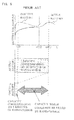
- Referring to
FIG. 8 , the above-described point will be described. As described above, when the rapid charge on an active battery, which is not in an inactive state, is continued, the active battery reaches a state of nearly full charge when the value of the battery voltage has become slightly lower than the peak value (for example, after 60 minutes from the start of the rapid charge shown inFIG. 8 ) after the value of the battery voltage passes the peak value. However, in general, when the rapid charge on the inactive battery has been done, the value of the battery voltage often reaches a peak value, which is different from the above-described peak value corresponding to the full charge, within a certain time period from starting the charge. For this reason, when the value of the battery voltage has passed the peak value different from the above-described primary peak value (for example, after 5 minutes from the start of the rapid charge shown inFIG. 8 ), such conventional rechargeable electrical devices often misdetermine that the rechargeable battery has reached a state of full charge, thereby stopping the rapid charge before full charge. As a countermeasure against this insufficient charge occurred in the inactive battery, such conventional rechargeable electrical devices continues the trickle charge after the stop of the rapid charge so as to simultaneously perform activating the inactive battery and charging the rechargeable battery to full charge by compensating for the capacity, shown by the two-headed arrow inFIG. 8 , which could not be filled by the rapid charge. - Patent document 1: Japanese Laid-open Patent Publication
Hei 6-14472 - However, the above-described conventional rechargeable electrical device, which continues a trickle charge after the stop of the rapid charge, continues to apply a trickle charge current with a constant current value to its rechargeable battery after the stop of the rapid charge in order to not only simultaneously perform activating and charging its inactive battery but also compensate for self-discharge of its rechargeable battery. Thus, the above-described conventional rechargeable electrical device has the below-described problem.
- In general, the value of the trickle charge current required to activate (and charge simultaneously) the inactive battery is larger than the value of the trickle charge current required to compensate for self-discharge of a rechargeable battery. Accordingly, the value of the trickle charge current, which is required after the inactive battery has been activated and charged to full charge once, is smaller than that required before the inactive battery is activated and charged to full charge once. Despite this, the above-described conventional rechargeable electrical device, which continues a trickle charge after the stop of the rapid charge, continues to apply a trickle charge current, which is required to simultaneously activate and charge the inactive battery and has a constant current value, to its rechargeable battery after the stop of the rapid charge. This results in wasteful power consumption.
- The present invention is conceived to solve the above-described problems of the conventional art and aimed to provide a rechargeable electrical device which can simultaneously perform activating and charging its inactive battery in the trickle charge, and can reduce power consumption required to charge its rechargeable battery.
- According to the present invention, this object is achieved by a rechargeable electrical device comprising: a rechargeable battery; a switching element provided between the rechargeable battery and a power source; and a control means which includes a time measuring means for measuring time, and which controls a duty cycle, which is a ratio of an on period and an off period of the switching element, based on time output from the time measuring means, so as to control a charging current value to the rechargeable battery. Charging the rechargeable battery includes both a rapid charge and a trickle charge to charge the rechargeable battery after a stop of the rapid charge with an electric current having a current value smaller than a charging current value in the rapid charge. The control means sets the charging current value in a first trickle charge after the stop of the rapid charge to a different value from the charging current value in second and subsequent trickle charges after the stop of the rapid charge.
- In the above-described configuration, the charging current value in the first trickle charge after the stop of the rapid charge is set to a different value from the charging current value in the second and subsequent trickle charges. Thus, for example, in the first trickle charge, charging can be performed with the charging current value required to simultaneously perform activating and charging an inactive battery. On the other hand, in the second and subsequent trickle charges, charging can be performed with the charging current value required to compensate for self-discharge of the rechargeable battery. Accordingly, in the first trickle charge, the rechargeable electrical device can simultaneously perform activating and charging the inactive battery. On the other hand, in the second and subsequent trickle charges, the rechargeable electrical device can charge the rechargeable battery with the charging current value required to compensate for self-discharge of the rechargeable battery. Thus, the rechargeable electrical device can reduce power consumption required to charge the rechargeable battery, as compared to the case where the trickle charge is continued with a constant charging current value, which is required to simultaneously activate and charge the inactive battery, as the conventional rechargeable electrical device.
- In this rechargeable electrical device, the control means may set a charging pause time between the rapid charge and the first trickle charge, and/or between each of first and subsequent trickle charges after the stop of the rapid charge.
- In this rechargeable electrical device, it is preferable that the control means sets the charging current value in the second and subsequent trickle charges to a value lower than the charging current value in the first trickle charge.
-
- [
FIG. 1 ]
FIG. 1 is a schematic circuit diagram of an electrical shaver, which is a rechargeable electrical device according to an embodiment of the present invention, and an adapter. - [
FIG. 2 ]
FIG. 2 is a graph showing a pattern of a rapid charge and a trickle charge in the above-described electrical shaver. - [
FIG. 3 ]
FIG. 3 is graphs each of which shows a pattern of the rapid charge and the trickle charge in the case of charging an active rechargeable battery and in the case of charging an inactive rechargeable battery in the above-described electrical shaver. - [
FIG. 4 ]
FIG. 4 is a graph showing one modified example of a pattern of the trickle charge in the above-described electrical shaver. - [
FIG. 5 ]
FIG. 5 is a graph showing another modified example of a pattern of the trickle charge in the above-described electrical shaver. - [
FIG. 6 ]
FIG. 6 is a graph showing another modified example of a pattern of the trickle charge in the above-described electrical shaver. - [
FIG. 7 ]
FIG. 7 is a graph showing another modified example of a pattern of the trickle charge in the above-described electrical shaver. - [
FIG. 8 ]
FIG. 8 is a graph showing that conventional rechargeable electrical devices cannot make an inactive nickel metal hydride rechargeable battery full charge only with the rapid charge. - An
electrical shaver 1, which is a rechargeable electrical device according to an embodiment of the present invention, will be described hereinafter with reference to the drawings.FIG. 1 is a schematic circuit diagram of an electrical shaver 1 (claimed "a rechargeable electrical device") according to this embodiment, and an adapter 11 to be connected to theelectrical shaver 1 for charging. Theelectrical shaver 1 is a rechargeable electrical shaver. Theelectrical shaver 1 comprises amotor 2 which is a load, arechargeable battery 3 for supplying power to themotor 2, and charge terminals 4a, 4b electrically connected to therechargeable battery 3. Therechargeable battery 3 is formed of a plurality of series-connected nickel metal hydride battery cells each with a normal cell voltage of 1.4V. Therechargeable battery 3 formed of a plurality of nickel metal hydride battery cells has a charge characteristic that if the charging of therechargeable battery 3 in an active state is started with a residual capacity less than a certain threshold value, therechargeable battery 3 reaches a state of nearly full charge when the value of the battery voltage of therechargeable battery 3 has become a value lower than a peak value after the value of the battery voltage passes the peak value. Charging therechargeable battery 3 in thiselectrical shaver 1 includes both a rapid charge and a trickle charge to charge therechargeable battery 3 after the stop of the rapid charge with an electric current having a current value smaller than the charging current value in the rapid charge. - The above-described
electrical shaver 1 comprises a microcomputer 5 (control means) to control the entireelectrical shaver 1, and aswitching element 6. Themicrocomputer 5 comprises a timer 8 (time measuring means) for measuring time. Themicrocomputer 5 controls a duty cycle which is a ratio of an on period and an off period of theswitching element 6 based on time output from the timer 8 so as to control a charging current value to therechargeable battery 3. Additionally, themicrocomputer 5 keeps the switchingelement 6 in the off-state for a predetermined time based on time output from the timer 8 in order to set a charging pause time between a rapid charge and the first trickle charge after the rapid charge, and/or between each of the first and subsequent trickle charges after the rapid charge. - The switching
element 6 is an n-channel enhancement type MOSFET (metal oxide semiconductor field effect transistor). This switchingelement 6 is provided between therechargeable battery 3 and the adapter 11 (i.e. between therechargeable battery 3 and a commercial power source 20). The switchingelement 6 switches between disconnection (off) and connection (on) of the path, which connects the charge terminal 4a and the positive terminal of therechargeable battery 3, according to high and low voltage levels of the control signal input from themicrocomputer 5 to the gate of theswitching element 6 through the line L5. More specifically, when the voltage level of the control signal input to the gate of theswitching element 6 is high, the drain-source path of theswitching element 6 is rendered conductive to connect the charging path from the charge terminal 4a to the positive terminal of therechargeable battery 3 so that therechargeable battery 3 is charged. On the other hand, when the voltage level of the control signal input to the gate of theswitching element 6 is low, the drain-source path of theswitching element 6 is rendered non-conductive to disconnect the charging path from the charge terminal 4a to the positive terminal of therechargeable battery 3 so as to prevent charging therechargeable battery 3. - A plurality of input and output terminals (not shown) of the
microcomputer 5 are respectively connected to lines L0 to L5. The line L0 is an input line for detecting a charging current value to therechargeable battery 3. Themicrocomputer 5 allows an input current to the line L0 to flow through an internal resistor provided inside themicrocomputer 5, and measures a voltage drop value due to the internal resistor, and further uses the voltage drop value to detect (determine) a charging current value to therechargeable battery 3. The line L1 is an input line for detecting a value of voltage at the positive terminal of therechargeable battery 3. The ground line (hereafter referred to as the GND line) L2 is an input line for detecting a value of voltage at the negative terminal of therechargeable battery 3. Based on the voltage applied to the line L1 and the voltage applied to the GND line L2, themicrocomputer 5 detects a value of battery voltage of therechargeable battery 3. - The line L3 is an input line to connect the
rechargeable battery 3 to themicrocomputer 5 for supplying power to themicrocomputer 5. Further, the line L4 is an input line for detecting a value of discharge current discharged from therechargeable battery 3 to themotor 2. Themicrocomputer 5 allows the input current to the line L4 to flow through an internal resistor provided inside themicrocomputer 5, and measures a voltage drop value due to the internal resistor, and further uses the voltage drop value to detect (determine) a discharging current value to themotor 2. Then, based on the detected discharging current value, themicrocomputer 5 prevents an overcurrent from flowing into themotor 2 which is a load. The line L5 is an output line for a control signal for controlling switching between connection and disconnection of the (charging) path from the charge terminal 4a to the positive terminal of therechargeable battery 3. Themicrocomputer 5 adjust (change) the duty cycle, which is a ratio of an on period and an off period of theswitching element 6, according to the level of the charging current value detected based on the input current to the line L0 so as to perform feedback control of the charging current value to therechargeable battery 3. - The above-described
electrical shaver 1 further comprises anoperation switch 7. When theoperation switch 7 is turned on and short-circuited by a user in use of theelectrical shaver 1, therechargeable battery 3 is electrically connected to themotor 2 to allow therechargeable battery 3 to supply power to themotor 2 so as to drive themotor 2. - Next, the adapter 11 will be described. The adapter 11 is a switching power supply unit to convert alternating-current (AC) power (voltage) from a
commercial power source 20 to direct-current (DC) power (voltage) so as to supply power (voltage) to theelectrical shaver 1. The adapter 11 comprises connection terminals 12a, 12b for connection to thecommercial power source 20 and power supply terminals 17a, 17b for connection (and power supply) to theelectrical shaver 1. When therechargeable battery 3 is charged, the connection terminals 12a, 12b of the adapter 11 are connected to thecommercial power source 20, and the power supply terminals 17a, 17b of the adapter 11 are connected to theelectrical shaver 1 to provide theelectrical shaver 1 with DC power based on the AC power supplied from thecommercial power source 20. - The adapter 11 comprises a
diode bridge 13 to convert AC voltage input from thecommercial power source 20 to DC ripple voltage, and a smoothing capacitor C1 to smooth the DC ripple voltage output from thediode bridge 13 and convert it to a substantially constant DC voltage. - The adapter 11 further comprises a
control circuit 14 for controlling the entire adapter 11, and a step-downvoltage converter circuit 15 to reduce the DC voltage supplied by the smoothing capacitor C1. Thecontrol circuit 14 is operated based on the DC voltage power supplied by thediode bridge 13 and the smoothing capacitor C1. The step-downvoltage converter circuit 15 comprises atransformer 18 to reduce voltage, and a transistor 16 for switching between a voltage applied state and a voltage non-applied state of voltage to a primary winding of thetransformer 18. The transistor 16 is a bipolar transistor of NPN type. - The
control circuit 14 switches between conduction (ON) and non-conduction (OFF) of the collector-emitter path of the transistor 16 by switching between high and low voltage levels applied to the base of the transistor 16 through an output line L7. By switching between conduction and non-conduction of the collector-emitter path of the transistor 16 as described above, thecontrol circuit 14 switches between the voltage applied state and the voltage non-applied state of voltage to the primary winding of thetransformer 18. Further, thecontrol circuit 14 controls a ratio of a high level period to a low level period of the voltage applied to the base of the transistor 16 so as to control a ratio (so-called duty cycle) of a conduction (ON) period and a non-conduction (OFF) period of the collector-emitter path. Thereby, thecontrol circuit 14 controls the voltage of power output from a secondary winding of thetransformer 18 to be substantially constant. - The adapter 11 further comprises a
transformer 19 for detecting a voltage level induced in the secondary winding of thetransformer 18. Thecontrol circuit 14 detects a value of voltage induced in thetransformer 19 through an input line L8 and a GND line L9 so as to perform feedback control of the duty cycle of the voltage applied to the base of the transistor 16 based on the detected value of the voltage of thetransformer 19. - The adapter 11 still further comprises a backflow preventing diode D1 to which the pulsed power output from the secondary winding of the
transformer 18 is applied, and a smoothing capacitor C2 for smoothing the voltage of the power output from the diode D1. - Referring now to
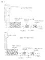
FIG. 2 , a method of trickle charging applied to theelectrical shaver 1 according to this embodiment will be described. In the method of trickle charging applied to theelectrical shaver 1, themicrocomputer 5 sets the charging current value in the first trickle charge after a stop of the rapid charge to a different value from the charging current value in the second and subsequent trickle charges after the stop of the rapid charge. Specifically, themicrocomputer 5 sets the charging current value (50 milliamperes) in the second and subsequent trickle charges to a value lower than the charging current value (100 milliamperes) in the first trickle charge. The charging current value (100 milliamperes) in the first trickle charge is the value of the current required to simultaneously perform activating and charging an inactive nickel metal hydride rechargeable battery (hereafter referred to as an inactive battery). The charging current value (50 milliamperes) in the second and subsequent trickle charges is the value of the trickle charge current required to compensate for self-discharge of a rechargeable battery. - As shown in
FIG. 2 , themicrocomputer 5 does not set a charging pause time between the rapid charge and the first trickle charge (i.e., sets a charging pause time after the rapid charge to 0 hours), but sets a charging pause time between each of the first and subsequent trickle charges. Specifically, by controlling theswitching element 6, themicrocomputer 5 performs the rapid charge with a current value of 1000 milliamperes for an hour, and subsequently shifts to the first trickle charge without a charging pause time. Themicrocomputer 5 charges therechargeable battery 3 with a current value of 100 milliamperes for eight hours in the first trickle charge, and then pauses charging for 3.5 hours. After this, themicrocomputer 5 repeats charging with a current value of 50 milliamperes for 2.5 hours in each of the second and subsequent trickle charges and pausing charging for 3.5 hours. Note that the above-described charging pause time between each of the first and subsequent trickle charges is set to a time which does not affect the use of the electrical shaver 1 (i.e., a time which is short enough to prevent theelectrical shaver 1 from becoming unable to be used due to self-discharge of therechargeable battery 3 and power consumption of the microcomputer 5). - In the case where the trickle charge is performed in the pattern shown in
FIG. 2 , therechargeable battery 3 can be made full charge, even if therechargeable battery 3 to be charged is inactive. This point will be described below with reference toFIG. 3. FIG. 3 shows graphs each of which shows a pattern of the rapid charge and the trickle charge in the case where theelectrical shaver 1 charges an active (rechargeable) battery and in the case where theelectrical shaver 1 charges the inactive battery. Similar to the conventional rechargeable electrical device described inPatent Document 1, theelectrical shaver 1 stops the rapid charge when the value of the battery voltage has become slightly lower than a peak value after passing the peak value, as shown inFIG. 8 . Thus, when therechargeable battery 3 to be charged is inactive, theelectrical shaver 1 often stops the rapid charge before full charge. Accordingly, as shown inFIG. 3 , when theelectrical shaver 1 charges the inactive battery, the rapid charge time becomes shorter than when theelectrical shaver 1 charges the active battery. This results in insufficient charge. - As a countermeasure against the above-described insufficient charge which is occurred in the inactive battery, the
microcomputer 5 of theelectrical shaver 1 charges therechargeable battery 3 with the value (100 milliamperes) of the current required to simultaneously perform activating and charging the inactive battery for eight hours in the first trickle charge after the rapid charge, as shown in the lower part ofFIG. 3 . By the first trickle charge, themicrocomputer 5 simultaneously performs activating the inactiverechargeable battery 3 and compensating for the capacity, which was not filled by the rapid charge and is indicated by the two-headed arrow inFIG. 8 , so as to charge therechargeable battery 3 to full charge. After this, as shown in the lower part ofFIG. 3 , themicrocomputer 5 charges therechargeable battery 3 in order to compensate for self-discharge of therechargeable battery 3 in each of the second and subsequent trickle charges. As described above, in theelectrical shaver 1, themicrocomputer 5 charges therechargeable battery 3 with the value of the current required to simultaneously perform activating and charging the inactive battery in the first trickle charge so as to be able to make therechargeable battery 3 full charge even if therechargeable battery 3 to be charged is inactive. - On the other hand, when the
rechargeable battery 3 to be charged is an active battery, therechargeable battery 3 is charged to a state of nearly full charge with the rapid charge. Accordingly, in this case, the purpose of charging in the first trickle charge is to compensate for self-discharge of therechargeable battery 3. - Next, referring to
FIGS. 4 to 7 , modified examples of the pattern of the trickle charges which are performed in theelectrical shaver 1 will be described. The pattern of the trickle charges shown inFIG. 4 is different from the pattern of the trickle charges shown inFIG. 2 in that a charging pause time is set between the rapid charge and the first trickle charge. Other points are basically the same as the pattern of the trickle charges shown inFIG. 2 . However, it is preferable that the period of the first trickle charge shown inFIG. 4 is longer than the period (eight hours) of the first trickle charge shown inFIG. 2 in order to compensate for a residual capacity shortage (due to self-discharge) caused by setting a charging pause time between the rapid charge and the first trickle charge. Alternatively, it is preferable that the charging current value in the first trickle charge shown inFIG. 4 is set higher than the charging current value (100 milliamperes) in the first trickle charge shown inFIG. 2 in order to compensate for the above-described residual capacity shortage. Note that the above-described charging pause time between the rapid charge and the first trickle charge is set to within the time which does not affect the activation (i.e., the time which is so short as not to affect the activation) of therechargeable battery 3. - The pattern of the trickle charges shown in
FIG. 5 is different from the pattern of the trickle charges shown inFIG. 4 in that a charging pause time is not set between each of the first and subsequent trickle charges. Other points are basically the same as the pattern of the trickle charges shown inFIG. 4 . However, in this pattern of the trickle charges, a charging pause time is not set between each of the first and subsequent trickle charges, and the second trickle charge is continued. This results in increased total time of the second trickle charge. Considering this increased total time of the second trickle charge, the charging current value (20 milliamperes) in the second trickle charge in the pattern of the trickle charges shown inFIG. 5 is set lower than the charging current value (50 milliamperes) in the second and subsequent trickle charges shown inFIG. 4 . - The pattern of the trickle charges shown in
FIG. 6 is different from the pattern of the trickle charges shown inFIG. 2 in that a charging pause time is not set between each of the first and subsequent trickle charges. Other points are basically the same as the pattern of the trickle charges shown inFIG. 2 . However, in this pattern of the trickle charges, a charging pause time is not set between each of the first and subsequent trickle charges, and the second trickle charge is continued. This results in increased total time of the second trickle charge. With this increased total time of the second trickle charge in mind, the charging current value (20 milliamperes) in the second trickle charge in the pattern of the trickle charges shown inFIG. 6 is set lower than the charging current value (50 milliamperes) in the second and subsequent trickle charges shown inFIG. 2 . - The pattern of the trickle charges shown in
FIG. 7 is different from the pattern of the trickle charges shown inFIG. 4 in that the charging current value (75 milliamperes) in the second trickle charge is set higher than the charging current value (50 milliamperes) in the third trickle charge. Other points are basically the same as the pattern of the trickle charges shown inFIG. 4 . Note that the charging current value in the fourth and subsequent trickle charge may be set lower than the charging current value (50 milliamperes) in the third trickle charge, or set equal to the charging current value in the third trickle charge. - As described above, according to the
electrical shaver 1 of the present embodiment, the charging current value in the first trickle charge after the rapid charge is set to a different value from the charging current value in the second and subsequent trickle charges. Specifically, the charging current value in the second and subsequent trickle charges is set to a value lower than the charging current value in the first trickle charge. More specifically, in the first trickle charge, charging is performed with the charging current value required to simultaneously perform activating and charging the inactive battery (therechargeable battery 3 which is inactive). On the other hand, in the second and subsequent trickle charges, charging is performed with the charging current value required to compensate for self-discharge of therechargeable battery 3. Accordingly, in the first trickle charge, theelectrical shaver 1 can simultaneously perform activating and charging the inactive battery. On the other hand, in the second and subsequent trickle charges, theelectrical shaver 1 charges therechargeable battery 3 with the charging current value required to compensate for self-discharge of therechargeable battery 3. Thus, theelectrical shaver 1 can reduce power consumption required to charge therechargeable battery 3, as compared to the case where the trickle charge is continued with a constant charging current value, which is required to simultaneously activate and charge the inactive battery, as the above-described conventional rechargeable electrical device. - Additionally, in the case where the pattern of the trickle charges performed in the
electrical shaver 1 is one of the patterns of the trickle charges shown inFIGs. 2 ,4 ,5 and7 , themicrocomputer 5 sets a charging pause time between the rapid charge and the first trickle charge, and/or between each of the first and subsequent trickle charges. Thus, theelectrical shaver 1 can further reduce power consumption required to charge therechargeable battery 3, as compared to the case where the trickle charge is continued with a constant current value, which is required to simultaneously activate and charge the inactive battery, as the conventional rechargeable electrical device. - It is to be noted that the present invention is not limited to the above-described embodiment, and various modifications are possible within the spirit and scope of the present invention. For example, although the embodiment described above shows an example in which a rechargeable electrical device of the present invention is the
electrical shaver 1, the present invention can be applied, for example, to a rechargeable electrical device such as a cellular phone or a portable information device. In addition, the rechargeable battery to be comprised in the rechargeable electrical device of the present invention is not necessarily a nickel metal hydride rechargeable battery. Further, although the embodiment described above shows an example in which theswitching element 6 is a MOSFET, the switchingelement 6 may be a bipolar type transistor. - This application is based on Japanese patent application
2011-205027
Claims (4)
- A rechargeable electrical device comprising:a rechargeable battery;a switching element provided between the rechargeable battery and a power source; anda control means which includes a time measuring means for measuring time, and which controls a duty cycle, which is a ratio of an on period and an off period of the switching element, based on time output from the time measuring means, so as to control a charging current value to the rechargeable battery,wherein charging the rechargeable battery includes both a rapid charge and a trickle charge to charge the rechargeable battery after a stop of the rapid charge with an electric current having a current value smaller than a charging current value in the rapid charge, andthe control means sets the charging current value in a first trickle charge after the stop of the rapid charge to a different value from the charging current value in second and subsequent trickle charges after the stop of the rapid charge.
- The rechargeable electrical device according to claim 1, wherein the control means sets a charging pause time between the rapid charge and the first trickle charge, and/or between each of first and subsequent trickle charges after the stop of the rapid charge.
- The rechargeable electrical device according to claim 2, wherein the control means sets the charging current value in the second and subsequent trickle charges to a value lower than the charging current value in the first trickle charge.
- le electrical device according to claim 1, wherein the control means sets the charging current value in the second and subsequent trickle charges to a value lower than the charging current value in the first trickle charge.
Applications Claiming Priority (2)
| Application Number | Priority Date | Filing Date | Title |
|---|---|---|---|
| JP2011205027A JP5919506B2 (en) | 2011-09-20 | 2011-09-20 | Rechargeable electrical equipment |
| PCT/JP2012/003823 WO2013042293A1 (en) | 2011-09-20 | 2012-06-12 | Rechargeable electrical device |
Publications (2)
| Publication Number | Publication Date |
|---|---|
| EP2760106A1 true EP2760106A1 (en) | 2014-07-30 |
| EP2760106A4 EP2760106A4 (en) | 2015-09-16 |
Family
ID=47914087
Family Applications (1)
| Application Number | Title | Priority Date | Filing Date |
|---|---|---|---|
| EP12833302.8A Withdrawn EP2760106A4 (en) | 2011-09-20 | 2012-06-12 | RECHARGEABLE ELECTRICAL DEVICE |
Country Status (6)
| Country | Link |
|---|---|
| US (1) | US9231417B2 (en) |
| EP (1) | EP2760106A4 (en) |
| JP (1) | JP5919506B2 (en) |
| CN (1) | CN103765724B (en) |
| RU (1) | RU2014108214A (en) |
| WO (1) | WO2013042293A1 (en) |
Families Citing this family (9)
| Publication number | Priority date | Publication date | Assignee | Title |
|---|---|---|---|---|
| KR101428293B1 (en) * | 2012-12-18 | 2014-08-07 | 현대자동차주식회사 | Sub battery charge method of electric vehicle |
| JP6214032B2 (en) * | 2013-08-08 | 2017-10-18 | 東芝テック株式会社 | Charge control device and program |
| TW201607193A (en) * | 2014-08-14 | 2016-02-16 | 菲利浦莫里斯製品股份有限公司 | Rechargeable device with short circuit prevention |
| JP6308092B2 (en) * | 2014-10-06 | 2018-04-11 | 株式会社デンソー | Electronic control unit |
| KR102502450B1 (en) * | 2015-11-02 | 2023-02-22 | 삼성전자주식회사 | Method and apparatus of charging battery |
| CN106100018B (en) * | 2016-06-13 | 2019-06-04 | Tcl移动通信科技(宁波)有限公司 | A kind of charge control method and system based on mobile terminal |
| WO2018012055A1 (en) * | 2016-07-13 | 2018-01-18 | ソニーモバイルコミュニケーションズ株式会社 | Information processing device, information processing system, and charging method |
| KR102544462B1 (en) | 2018-01-25 | 2023-06-19 | 삼성전자 주식회사 | Electronic device comprising battery and method for controlling charging thereof |
| TWI784788B (en) * | 2021-11-10 | 2022-11-21 | 技嘉科技股份有限公司 | Power supply regulating circuit, charging device and power supply mode adjustment method thereof |
Family Cites Families (21)
| Publication number | Priority date | Publication date | Assignee | Title |
|---|---|---|---|---|
| JPS645334A (en) * | 1987-06-24 | 1989-01-10 | Matsushita Electric Works Ltd | Boosting charge control device |
| JPH01180145U (en) * | 1988-06-06 | 1989-12-25 | ||
| JP3457681B2 (en) * | 1991-01-28 | 2003-10-20 | 松下電工株式会社 | Charging device |
| JPH05137271A (en) * | 1991-11-08 | 1993-06-01 | Nec Corp | Charging method of battery |
| US5315228A (en) | 1992-01-24 | 1994-05-24 | Compaq Computer Corp. | Battery charge monitor and fuel gauge |
| JPH0614472A (en) | 1992-06-24 | 1994-01-21 | Sanyo Electric Co Ltd | Battery charger |
| CA2098468C (en) * | 1992-07-07 | 1998-09-01 | David J. Theobald | Method for battery charging |
| JP3499902B2 (en) * | 1992-07-17 | 2004-02-23 | ペンタックス株式会社 | Rechargeable battery charger |
| US5539298A (en) * | 1993-03-19 | 1996-07-23 | Compaq Computer Corporation | Pulse charge technique to trickle charge a rechargeable battery |
| US5412306A (en) * | 1993-09-14 | 1995-05-02 | Motorola, Inc. | Method and apparatus for charging a battery |
| US6104165A (en) | 1995-06-16 | 2000-08-15 | Zip Charge Corporation | Multi-stage battery charging system |
| JP2743155B2 (en) | 1995-06-16 | 1998-04-22 | 株式会社ジップチャージ | Charger and charge processing system |
| US5998968A (en) | 1997-01-07 | 1999-12-07 | Ion Control Solutions, Llc | Method and apparatus for rapidly charging and reconditioning a battery |
| EP0964497B1 (en) | 1998-06-09 | 2010-10-13 | Makita Corporation | Battery charger |
| US6172480B1 (en) | 1998-10-23 | 2001-01-09 | Primetech Electronics, Inc. | Compact fast battery charger |
| US20010048287A1 (en) * | 2000-11-01 | 2001-12-06 | Jean-Pierre Vandelac | Compact fast battery charger |
| US7176654B2 (en) * | 2002-11-22 | 2007-02-13 | Milwaukee Electric Tool Corporation | Method and system of charging multi-cell lithium-based batteries |
| JP2007259632A (en) * | 2006-03-24 | 2007-10-04 | Nec Personal Products Co Ltd | Charging circuit and charging control method |
| JP5020530B2 (en) * | 2006-04-14 | 2012-09-05 | パナソニック株式会社 | Charging method, battery pack and charger thereof |
| JP2009232669A (en) * | 2008-02-29 | 2009-10-08 | Oki Electric Ind Co Ltd | Battery backup unit |
| CN101546919B (en) * | 2009-01-21 | 2011-08-24 | 炬力集成电路设计有限公司 | Method and device for charging battery |
-
2011
- 2011-09-20 JP JP2011205027A patent/JP5919506B2/en not_active Expired - Fee Related
-
2012
- 2012-06-12 RU RU2014108214/07A patent/RU2014108214A/en not_active Application Discontinuation
- 2012-06-12 WO PCT/JP2012/003823 patent/WO2013042293A1/en active Application Filing
- 2012-06-12 US US14/342,699 patent/US9231417B2/en active Active
- 2012-06-12 EP EP12833302.8A patent/EP2760106A4/en not_active Withdrawn
- 2012-06-12 CN CN201280040621.1A patent/CN103765724B/en active Active
Also Published As
| Publication number | Publication date |
|---|---|
| JP2013070442A (en) | 2013-04-18 |
| US9231417B2 (en) | 2016-01-05 |
| EP2760106A4 (en) | 2015-09-16 |
| CN103765724B (en) | 2016-04-13 |
| CN103765724A (en) | 2014-04-30 |
| WO2013042293A1 (en) | 2013-03-28 |
| JP5919506B2 (en) | 2016-05-18 |
| RU2014108214A (en) | 2015-10-27 |
| US20140225573A1 (en) | 2014-08-14 |
Similar Documents
| Publication | Publication Date | Title |
|---|---|---|
| US9231417B2 (en) | Rechargeable electrical device | |
| CN107894567B (en) | Battery pack and detection system and detection method for interface state of battery pack | |
| JP5974500B2 (en) | Charge control device with protection function and battery pack | |
| US8698450B2 (en) | Bidirectional wireless charging and discharging device for portable electronic device | |
| US9219368B2 (en) | Charge controller with protection function and battery pack | |
| US8008807B2 (en) | Uninterruptible power supply with low power loss | |
| WO2006073101A1 (en) | Mobile telephone terminal charging control device and charging control method | |
| KR20140108143A (en) | Charge and discharge control circuit and battery device | |
| US8093865B2 (en) | Charging device with backflow prevention | |
| WO2005076099A1 (en) | Enabling circuit for avoiding negative voltage transients | |
| US9509150B2 (en) | Charging circuit and control method therefor | |
| US8729853B2 (en) | Wireless charging device for portable electronic device | |
| KR102411269B1 (en) | Low heat wireless power receiving device | |
| CN214045155U (en) | Charging protection circuit and charger | |
| EP2571136B1 (en) | Power supply device | |
| WO2016031098A1 (en) | Power supply device | |
| CN115706422A (en) | Charging system, charging system control method, device, and electronic equipment | |
| JP3726339B2 (en) | Secondary battery charging device, control circuit thereof, and charging processing method | |
| JP2010288403A (en) | Battery pack charge control device | |
| TWI519035B (en) | Charger for rechargeable battery and charging method thereof | |
| JP2012205412A (en) | Charging circuit, and portable device | |
| JP2004088923A (en) | Secondary battery charge/discharge circuit and electronic apparatus with the same |
Legal Events
| Date | Code | Title | Description |
|---|---|---|---|
| PUAI | Public reference made under article 153(3) epc to a published international application that has entered the european phase |
Free format text: ORIGINAL CODE: 0009012 |
|
| 17P | Request for examination filed |
Effective date: 20140211 |
|
| AK | Designated contracting states |
Kind code of ref document: A1 Designated state(s): AL AT BE BG CH CY CZ DE DK EE ES FI FR GB GR HR HU IE IS IT LI LT LU LV MC MK MT NL NO PL PT RO RS SE SI SK SM TR |
|
| DAX | Request for extension of the european patent (deleted) | ||
| RA4 | Supplementary search report drawn up and despatched (corrected) |
Effective date: 20150814 |
|
| RIC1 | Information provided on ipc code assigned before grant |
Ipc: H01M 10/44 20060101ALI20150810BHEP Ipc: H02J 7/04 20060101AFI20150810BHEP |
|
| 17Q | First examination report despatched |
Effective date: 20170601 |
|
| STAA | Information on the status of an ep patent application or granted ep patent |
Free format text: STATUS: THE APPLICATION IS DEEMED TO BE WITHDRAWN |
|
| 18D | Application deemed to be withdrawn |
Effective date: 20191008 |