EP2760106A1 - Wiederaufladbare elektrische vorrichtung - Google Patents
Wiederaufladbare elektrische vorrichtung Download PDFInfo
- Publication number
- EP2760106A1 EP2760106A1 EP12833302.8A EP12833302A EP2760106A1 EP 2760106 A1 EP2760106 A1 EP 2760106A1 EP 12833302 A EP12833302 A EP 12833302A EP 2760106 A1 EP2760106 A1 EP 2760106A1
- Authority
- EP
- European Patent Office
- Prior art keywords
- charge
- trickle
- current value
- rechargeable battery
- charging
- Prior art date
- Legal status (The legal status is an assumption and is not a legal conclusion. Google has not performed a legal analysis and makes no representation as to the accuracy of the status listed.)
- Withdrawn
Links
Images


Classifications
-
- H—ELECTRICITY
- H02—GENERATION; CONVERSION OR DISTRIBUTION OF ELECTRIC POWER
- H02J—CIRCUIT ARRANGEMENTS OR SYSTEMS FOR SUPPLYING OR DISTRIBUTING ELECTRIC POWER; SYSTEMS FOR STORING ELECTRIC ENERGY
- H02J7/00—Circuit arrangements for charging or depolarising batteries or for supplying loads from batteries
- H02J7/02—Circuit arrangements for charging or depolarising batteries or for supplying loads from batteries for charging batteries from ac mains by converters
- H02J7/04—Regulation of charging current or voltage
-
- H—ELECTRICITY
- H01—ELECTRIC ELEMENTS
- H01M—PROCESSES OR MEANS, e.g. BATTERIES, FOR THE DIRECT CONVERSION OF CHEMICAL ENERGY INTO ELECTRICAL ENERGY
- H01M10/00—Secondary cells; Manufacture thereof
- H01M10/42—Methods or arrangements for servicing or maintenance of secondary cells or secondary half-cells
- H01M10/44—Methods for charging or discharging
- H01M10/448—End of discharge regulating measures
-
- H—ELECTRICITY
- H02—GENERATION; CONVERSION OR DISTRIBUTION OF ELECTRIC POWER
- H02J—CIRCUIT ARRANGEMENTS OR SYSTEMS FOR SUPPLYING OR DISTRIBUTING ELECTRIC POWER; SYSTEMS FOR STORING ELECTRIC ENERGY
- H02J7/00—Circuit arrangements for charging or depolarising batteries or for supplying loads from batteries
- H02J7/0029—Circuit arrangements for charging or depolarising batteries or for supplying loads from batteries with safety or protection devices or circuits
- H02J7/00304—Overcurrent protection
-
- H—ELECTRICITY
- H02—GENERATION; CONVERSION OR DISTRIBUTION OF ELECTRIC POWER
- H02J—CIRCUIT ARRANGEMENTS OR SYSTEMS FOR SUPPLYING OR DISTRIBUTING ELECTRIC POWER; SYSTEMS FOR STORING ELECTRIC ENERGY
- H02J7/00—Circuit arrangements for charging or depolarising batteries or for supplying loads from batteries
- H02J7/007—Regulation of charging or discharging current or voltage
-
- H—ELECTRICITY
- H01—ELECTRIC ELEMENTS
- H01M—PROCESSES OR MEANS, e.g. BATTERIES, FOR THE DIRECT CONVERSION OF CHEMICAL ENERGY INTO ELECTRICAL ENERGY
- H01M2220/00—Batteries for particular applications
- H01M2220/30—Batteries in portable systems, e.g. mobile phone, laptop
-
- H—ELECTRICITY
- H02—GENERATION; CONVERSION OR DISTRIBUTION OF ELECTRIC POWER
- H02J—CIRCUIT ARRANGEMENTS OR SYSTEMS FOR SUPPLYING OR DISTRIBUTING ELECTRIC POWER; SYSTEMS FOR STORING ELECTRIC ENERGY
- H02J7/00—Circuit arrangements for charging or depolarising batteries or for supplying loads from batteries
- H02J7/0029—Circuit arrangements for charging or depolarising batteries or for supplying loads from batteries with safety or protection devices or circuits
- H02J7/00302—Overcharge protection
-
- Y—GENERAL TAGGING OF NEW TECHNOLOGICAL DEVELOPMENTS; GENERAL TAGGING OF CROSS-SECTIONAL TECHNOLOGIES SPANNING OVER SEVERAL SECTIONS OF THE IPC; TECHNICAL SUBJECTS COVERED BY FORMER USPC CROSS-REFERENCE ART COLLECTIONS [XRACs] AND DIGESTS
- Y02—TECHNOLOGIES OR APPLICATIONS FOR MITIGATION OR ADAPTATION AGAINST CLIMATE CHANGE
- Y02E—REDUCTION OF GREENHOUSE GAS [GHG] EMISSIONS, RELATED TO ENERGY GENERATION, TRANSMISSION OR DISTRIBUTION
- Y02E60/00—Enabling technologies; Technologies with a potential or indirect contribution to GHG emissions mitigation
- Y02E60/10—Energy storage using batteries
Definitions
- Ni-MH nickel metal hydride
- the rechargeable electrical device using the nickel metal hydride rechargeable battery as a rechargeable battery continues charging with a minute electric current having a constant current value smaller than the charging current value in the rapid charge in order to either compensate for self-discharge of the rechargeable battery or activate the rechargeable battery in an inactive state.
- the above-described charging with a minute electric current having a constant current value is called a trickle charge.
- the above-described conventional rechargeable electrical device which continues a trickle charge after the stop of the rapid charge, continues to apply a trickle charge current with a constant current value to its rechargeable battery after the stop of the rapid charge in order to not only simultaneously perform activating and charging its inactive battery but also compensate for self-discharge of its rechargeable battery.
- the above-described conventional rechargeable electrical device has the below-described problem.
- the present invention is conceived to solve the above-described problems of the conventional art and aimed to provide a rechargeable electrical device which can simultaneously perform activating and charging its inactive battery in the trickle charge, and can reduce power consumption required to charge its rechargeable battery.
- the charging current value in the first trickle charge after the stop of the rapid charge is set to a different value from the charging current value in the second and subsequent trickle charges.
- charging can be performed with the charging current value required to simultaneously perform activating and charging an inactive battery.
- the second and subsequent trickle charges charging can be performed with the charging current value required to compensate for self-discharge of the rechargeable battery.
- the rechargeable electrical device can simultaneously perform activating and charging the inactive battery.
- the rechargeable electrical device can charge the rechargeable battery with the charging current value required to compensate for self-discharge of the rechargeable battery.
- the rechargeable electrical device can reduce power consumption required to charge the rechargeable battery, as compared to the case where the trickle charge is continued with a constant charging current value, which is required to simultaneously activate and charge the inactive battery, as the conventional rechargeable electrical device.
- control means may set a charging pause time between the rapid charge and the first trickle charge, and/or between each of first and subsequent trickle charges after the stop of the rapid charge.
- control means sets the charging current value in the second and subsequent trickle charges to a value lower than the charging current value in the first trickle charge.
- FIG. 1 is a schematic circuit diagram of an electrical shaver 1 (claimed “a rechargeable electrical device") according to this embodiment, and an adapter 11 to be connected to the electrical shaver 1 for charging.
- the electrical shaver 1 is a rechargeable electrical shaver.
- the electrical shaver 1 comprises a motor 2 which is a load, a rechargeable battery 3 for supplying power to the motor 2, and charge terminals 4a, 4b electrically connected to the rechargeable battery 3.
- the rechargeable battery 3 is formed of a plurality of series-connected nickel metal hydride battery cells each with a normal cell voltage of 1.4V.
- the line L3 is an input line to connect the rechargeable battery 3 to the microcomputer 5 for supplying power to the microcomputer 5.
- the line L4 is an input line for detecting a value of discharge current discharged from the rechargeable battery 3 to the motor 2.
- the microcomputer 5 allows the input current to the line L4 to flow through an internal resistor provided inside the microcomputer 5, and measures a voltage drop value due to the internal resistor, and further uses the voltage drop value to detect (determine) a discharging current value to the motor 2. Then, based on the detected discharging current value, the microcomputer 5 prevents an overcurrent from flowing into the motor 2 which is a load.
- the above-described electrical shaver 1 further comprises an operation switch 7.
- the operation switch 7 When the operation switch 7 is turned on and short-circuited by a user in use of the electrical shaver 1, the rechargeable battery 3 is electrically connected to the motor 2 to allow the rechargeable battery 3 to supply power to the motor 2 so as to drive the motor 2.
- the adapter 11 is a switching power supply unit to convert alternating-current (AC) power (voltage) from a commercial power source 20 to direct-current (DC) power (voltage) so as to supply power (voltage) to the electrical shaver 1.
- the adapter 11 comprises connection terminals 12a, 12b for connection to the commercial power source 20 and power supply terminals 17a, 17b for connection (and power supply) to the electrical shaver 1.
- connection terminals 12a, 12b of the adapter 11 are connected to the commercial power source 20, and the power supply terminals 17a, 17b of the adapter 11 are connected to the electrical shaver 1 to provide the electrical shaver 1 with DC power based on the AC power supplied from the commercial power source 20.
- the adapter 11 comprises a diode bridge 13 to convert AC voltage input from the commercial power source 20 to DC ripple voltage, and a smoothing capacitor C1 to smooth the DC ripple voltage output from the diode bridge 13 and convert it to a substantially constant DC voltage.
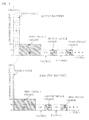
- the microcomputer 5 sets the charging current value in the first trickle charge after a stop of the rapid charge to a different value from the charging current value in the second and subsequent trickle charges after the stop of the rapid charge. Specifically, the microcomputer 5 sets the charging current value (50 milliamperes) in the second and subsequent trickle charges to a value lower than the charging current value (100 milliamperes) in the first trickle charge.
- the electrical shaver 1 when the rechargeable battery 3 to be charged is inactive, the electrical shaver 1 often stops the rapid charge before full charge. Accordingly, as shown in FIG. 3 , when the electrical shaver 1 charges the inactive battery, the rapid charge time becomes shorter than when the electrical shaver 1 charges the active battery. This results in insufficient charge.
- the microcomputer 5 of the electrical shaver 1 charges the rechargeable battery 3 with the value (100 milliamperes) of the current required to simultaneously perform activating and charging the inactive battery for eight hours in the first trickle charge after the rapid charge, as shown in the lower part of FIG. 3 .
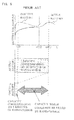
- the microcomputer 5 simultaneously performs activating the inactive rechargeable battery 3 and compensating for the capacity, which was not filled by the rapid charge and is indicated by the two-headed arrow in FIG. 8 , so as to charge the rechargeable battery 3 to full charge. After this, as shown in the lower part of FIG.
- the microcomputer 5 charges the rechargeable battery 3 in order to compensate for self-discharge of the rechargeable battery 3 in each of the second and subsequent trickle charges.
- the microcomputer 5 charges the rechargeable battery 3 with the value of the current required to simultaneously perform activating and charging the inactive battery in the first trickle charge so as to be able to make the rechargeable battery 3 full charge even if the rechargeable battery 3 to be charged is inactive.
- the charging current value in the first trickle charge after the rapid charge is set to a different value from the charging current value in the second and subsequent trickle charges.
- the charging current value in the second and subsequent trickle charges is set to a value lower than the charging current value in the first trickle charge.
- charging is performed with the charging current value required to simultaneously perform activating and charging the inactive battery (the rechargeable battery 3 which is inactive).
- the second and subsequent trickle charges charging is performed with the charging current value required to compensate for self-discharge of the rechargeable battery 3.
Applications Claiming Priority (2)
| Application Number | Priority Date | Filing Date | Title |
|---|---|---|---|
| JP2011205027A JP5919506B2 (ja) | 2011-09-20 | 2011-09-20 | 充電式電気機器 |
| PCT/JP2012/003823 WO2013042293A1 (ja) | 2011-09-20 | 2012-06-12 | 充電式電気機器 |
Publications (2)
| Publication Number | Publication Date |
|---|---|
| EP2760106A1 true EP2760106A1 (de) | 2014-07-30 |
| EP2760106A4 EP2760106A4 (de) | 2015-09-16 |
Family
ID=47914087
Family Applications (1)
| Application Number | Title | Priority Date | Filing Date |
|---|---|---|---|
| EP12833302.8A Withdrawn EP2760106A4 (de) | 2011-09-20 | 2012-06-12 | Wiederaufladbare elektrische vorrichtung |
Country Status (6)
| Country | Link |
|---|---|
| US (1) | US9231417B2 (de) |
| EP (1) | EP2760106A4 (de) |
| JP (1) | JP5919506B2 (de) |
| CN (1) | CN103765724B (de) |
| RU (1) | RU2014108214A (de) |
| WO (1) | WO2013042293A1 (de) |
Families Citing this family (9)
| Publication number | Priority date | Publication date | Assignee | Title |
|---|---|---|---|---|
| KR101428293B1 (ko) * | 2012-12-18 | 2014-08-07 | 현대자동차주식회사 | 전기자동차용 보조배터리의 주기적 충전 방법 |
| JP6214032B2 (ja) * | 2013-08-08 | 2017-10-18 | 東芝テック株式会社 | 充電制御装置及びプログラム |
| TW201607193A (zh) * | 2014-08-14 | 2016-02-16 | 菲利浦莫里斯製品股份有限公司 | 具有短路防止之可再充電裝置 |
| JP6308092B2 (ja) * | 2014-10-06 | 2018-04-11 | 株式会社デンソー | 電子制御装置 |
| KR102502450B1 (ko) * | 2015-11-02 | 2023-02-22 | 삼성전자주식회사 | 배터리 충전 방법 및 배터리 충전 장치 |
| CN106100018B (zh) * | 2016-06-13 | 2019-06-04 | Tcl移动通信科技(宁波)有限公司 | 一种基于移动终端的充电控制方法及系统 |
| CN109417300B (zh) * | 2016-07-13 | 2023-04-28 | 索尼移动通信株式会社 | 信息处理装置和充电方法 |
| KR102544462B1 (ko) | 2018-01-25 | 2023-06-19 | 삼성전자 주식회사 | 배터리를 포함하는 전자 장치 및 이의 충전구간을 제어하는 방법 |
| TWI784788B (zh) * | 2021-11-10 | 2022-11-21 | 技嘉科技股份有限公司 | 供電調控電路、充電裝置與其供電模式調整方法 |
Family Cites Families (21)
| Publication number | Priority date | Publication date | Assignee | Title |
|---|---|---|---|---|
| JPS645334A (en) * | 1987-06-24 | 1989-01-10 | Matsushita Electric Works Ltd | Boosting charge control device |
| JPH01180145U (de) * | 1988-06-06 | 1989-12-25 | ||
| JP3457681B2 (ja) * | 1991-01-28 | 2003-10-20 | 松下電工株式会社 | 充電装置 |
| JPH05137271A (ja) | 1991-11-08 | 1993-06-01 | Nec Corp | 電池充電方法 |
| US5315228A (en) * | 1992-01-24 | 1994-05-24 | Compaq Computer Corp. | Battery charge monitor and fuel gauge |
| JPH0614472A (ja) | 1992-06-24 | 1994-01-21 | Sanyo Electric Co Ltd | 充電器 |
| CA2098468C (en) | 1992-07-07 | 1998-09-01 | David J. Theobald | Method for battery charging |
| JP3499902B2 (ja) * | 1992-07-17 | 2004-02-23 | ペンタックス株式会社 | 二次電池充電装置 |
| US5539298A (en) * | 1993-03-19 | 1996-07-23 | Compaq Computer Corporation | Pulse charge technique to trickle charge a rechargeable battery |
| US5412306A (en) * | 1993-09-14 | 1995-05-02 | Motorola, Inc. | Method and apparatus for charging a battery |
| JP2743155B2 (ja) * | 1995-06-16 | 1998-04-22 | 株式会社ジップチャージ | 充電装置及び充電処理システム |
| US6104165A (en) | 1995-06-16 | 2000-08-15 | Zip Charge Corporation | Multi-stage battery charging system |
| US5998968A (en) | 1997-01-07 | 1999-12-07 | Ion Control Solutions, Llc | Method and apparatus for rapidly charging and reconditioning a battery |
| DE69942848D1 (de) * | 1998-06-09 | 2010-11-25 | Makita Corp | Batterieladegerät |
| US6172480B1 (en) | 1998-10-23 | 2001-01-09 | Primetech Electronics, Inc. | Compact fast battery charger |
| US20010048287A1 (en) * | 2000-11-01 | 2001-12-06 | Jean-Pierre Vandelac | Compact fast battery charger |
| US7176654B2 (en) * | 2002-11-22 | 2007-02-13 | Milwaukee Electric Tool Corporation | Method and system of charging multi-cell lithium-based batteries |
| JP2007259632A (ja) * | 2006-03-24 | 2007-10-04 | Nec Personal Products Co Ltd | 充電回路及び充電制御方法 |
| JP5020530B2 (ja) * | 2006-04-14 | 2012-09-05 | パナソニック株式会社 | 充電方法ならびに電池パックおよびその充電器 |
| JP2009232669A (ja) * | 2008-02-29 | 2009-10-08 | Oki Electric Ind Co Ltd | バッテリバックアップ装置 |
| CN101546919B (zh) * | 2009-01-21 | 2011-08-24 | 炬力集成电路设计有限公司 | 一种电池充电方法及装置 |
-
2011
- 2011-09-20 JP JP2011205027A patent/JP5919506B2/ja active Active
-
2012
- 2012-06-12 WO PCT/JP2012/003823 patent/WO2013042293A1/ja active Application Filing
- 2012-06-12 US US14/342,699 patent/US9231417B2/en active Active
- 2012-06-12 RU RU2014108214/07A patent/RU2014108214A/ru not_active Application Discontinuation
- 2012-06-12 CN CN201280040621.1A patent/CN103765724B/zh active Active
- 2012-06-12 EP EP12833302.8A patent/EP2760106A4/de not_active Withdrawn
Also Published As
| Publication number | Publication date |
|---|---|
| US9231417B2 (en) | 2016-01-05 |
| WO2013042293A1 (ja) | 2013-03-28 |
| CN103765724A (zh) | 2014-04-30 |
| CN103765724B (zh) | 2016-04-13 |
| US20140225573A1 (en) | 2014-08-14 |
| JP2013070442A (ja) | 2013-04-18 |
| EP2760106A4 (de) | 2015-09-16 |
| RU2014108214A (ru) | 2015-10-27 |
| JP5919506B2 (ja) | 2016-05-18 |
Similar Documents
| Publication | Publication Date | Title |
|---|---|---|
| US9231417B2 (en) | Rechargeable electrical device | |
| CN107894567B (zh) | 电池包以及电池包接口状态的检测系统和检测方法 | |
| JP5974500B2 (ja) | 保護機能付き充電制御装置および電池パック | |
| US8698450B2 (en) | Bidirectional wireless charging and discharging device for portable electronic device | |
| US9219368B2 (en) | Charge controller with protection function and battery pack | |
| US8008807B2 (en) | Uninterruptible power supply with low power loss | |
| WO2006073101A1 (ja) | 携帯電話端末の充電制御装置及び充電制御方法 | |
| WO2005076099A1 (en) | Enabling circuit for avoiding negative voltage transients | |
| US8093865B2 (en) | Charging device with backflow prevention | |
| CN102118057B (zh) | 具有整合式充放电路的直流不间断电源电路 | |
| US9509150B2 (en) | Charging circuit and control method therefor | |
| KR102411269B1 (ko) | 저발열 무선 전력 수신 장치 | |
| US8729853B2 (en) | Wireless charging device for portable electronic device | |
| CN214045155U (zh) | 充电保护电路及充电器 | |
| EP2571136B1 (de) | Stromversorgungsvorrichtung | |
| CN113169564A (zh) | 电池组及电气设备系统 | |
| JP3726339B2 (ja) | 二次電池の充電装置およびその制御回路ならびに充電処理方法 | |
| WO2016031098A1 (ja) | 電源装置 | |
| CN213693214U (zh) | 电子钱包供电电路和电子钱包 | |
| JP2010288403A (ja) | 組電池充電制御装置 | |
| CN115549258A (zh) | 充电电路、充电方法和电子设备 | |
| TWI519035B (zh) | 用於充電電池的充電器及其充電方法 | |
| JP2012205412A (ja) | 充電回路、及び携帯機器 | |
| JP2004088923A (ja) | 二次電池充放電回路及びこれを有する電子機器 |
Legal Events
| Date | Code | Title | Description |
|---|---|---|---|
| PUAI | Public reference made under article 153(3) epc to a published international application that has entered the european phase |
Free format text: ORIGINAL CODE: 0009012 |
|
| 17P | Request for examination filed |
Effective date: 20140211 |
|
| AK | Designated contracting states |
Kind code of ref document: A1 Designated state(s): AL AT BE BG CH CY CZ DE DK EE ES FI FR GB GR HR HU IE IS IT LI LT LU LV MC MK MT NL NO PL PT RO RS SE SI SK SM TR |
|
| DAX | Request for extension of the european patent (deleted) | ||
| RA4 | Supplementary search report drawn up and despatched (corrected) |
Effective date: 20150814 |
|
| RIC1 | Information provided on ipc code assigned before grant |
Ipc: H01M 10/44 20060101ALI20150810BHEP Ipc: H02J 7/04 20060101AFI20150810BHEP |
|
| 17Q | First examination report despatched |
Effective date: 20170601 |
|
| STAA | Information on the status of an ep patent application or granted ep patent |
Free format text: STATUS: THE APPLICATION IS DEEMED TO BE WITHDRAWN |
|
| 18D | Application deemed to be withdrawn |
Effective date: 20191008 |