WO2013035233A1 - 呼処理装置、着信呼転送システム、着信履歴取り扱い方法 - Google Patents
呼処理装置、着信呼転送システム、着信履歴取り扱い方法 Download PDFInfo
- Publication number
- WO2013035233A1 WO2013035233A1 PCT/JP2012/004565 JP2012004565W WO2013035233A1 WO 2013035233 A1 WO2013035233 A1 WO 2013035233A1 JP 2012004565 W JP2012004565 W JP 2012004565W WO 2013035233 A1 WO2013035233 A1 WO 2013035233A1
- Authority
- WO
- WIPO (PCT)
- Prior art keywords
- incoming call
- terminal device
- transfer
- call
- response
- Prior art date
- Legal status (The legal status is an assumption and is not a legal conclusion. Google has not performed a legal analysis and makes no representation as to the accuracy of the status listed.)
- Ceased
Links
Images


Classifications
-
- H—ELECTRICITY
- H04—ELECTRIC COMMUNICATION TECHNIQUE
- H04M—TELEPHONIC COMMUNICATION
- H04M3/00—Automatic or semi-automatic exchanges
- H04M3/42—Systems providing special services or facilities to subscribers
- H04M3/54—Arrangements for diverting calls for one subscriber to another predetermined subscriber
Definitions
- the present invention relates to a call processing device, an incoming call transfer system, and an incoming call history handling method for preventing an unnecessary call back from a terminal device that is a transfer source of an incoming call transfer service to a terminal device that is a transmission source. .
- the transfer source terminal is used regardless of whether the transfer destination terminal apparatus responds to the transferred incoming call.
- An incoming call history is uniformly held in the device. For this reason, a user who sees the incoming call history in the transfer source terminal device also induces a useless action such as calling back from the transfer source terminal device to the call origination terminal device even for the above-mentioned response completed. There was a risk of it.
- the response monitoring unit monitors the response status from the terminal device to which the incoming call is transferred, and if it is determined that the execution condition is satisfied as a result of the monitoring, A message requesting a callback is displayed on the incoming call history display screen.
- the technique of Patent Document 1 it is not possible to prevent an unnecessary call back from a transfer source terminal device due to an incoming call history remaining in a transfer source when using an incoming call transfer service.
- the present invention has been made in view of the above situation, and an unnecessary call from the transfer source terminal device due to the incoming call history remaining in the transfer source terminal device when using the incoming call transfer service. It is an object of the present invention to provide a call processing device, an incoming call transfer system, and an incoming call history handling method that eliminate the possibility of inducing back.
- one embodiment of the present invention provides: A call processing device applied to an incoming call transfer system for transferring an incoming call from a source terminal device to a transfer source terminal device to a transfer destination terminal device, A transfer source response status monitoring unit that monitors whether or not the transfer source terminal device has transmitted a response within a predetermined time with respect to an incoming call from the call source terminal device; When the transfer source response status monitoring unit detects that the transfer source terminal device does not send a response within a predetermined time for an incoming call from the call source terminal device, An incoming call transfer processing unit for transferring an incoming call from a terminal device to the transfer destination terminal device; A transfer destination response status monitoring unit that monitors a response status of the transfer destination terminal device for an incoming call from the call source terminal device transferred by the incoming call transfer processing unit; The forwarding destination response status monitoring unit responds to the incoming call from the originating terminal device transferred by the incoming call forwarding processing unit that the forwarding destination terminal device is connectable.
- the transfer source response status monitoring unit detects that the transfer source terminal device does not send a response within a predetermined time, and the transfer source terminal device subscribes to a predetermined incoming call transfer service.
- a predetermined transfer flag indicating that the incoming call is transferred is turned on and managed, and the incoming call from the originating terminal device transferred by the incoming call transfer processing unit is further controlled.
- the response from the transfer destination terminal device is a response indicating that connection is impossible, the transfer flag that has been managed with the switch turned off is managed,
- the incoming call history deletion request unit may not issue the incoming call history deletion request to the transfer source terminal device when the transfer flag is off. According to such a configuration, it is possible to eliminate the waste of issuing an incoming call history deletion request even to a transfer source terminal device that does not have an incoming call history, based on the determination based on the state of the transfer flag.
- the incoming call history deletion request unit monitors whether or not the incoming call history has been deleted in the transfer source terminal device, and when the deletion of the incoming call history has not been completed, The incoming call history deletion request may be repeatedly issued to the original terminal device. According to such a configuration, it is possible to thoroughly delete unnecessary incoming call histories in the transfer source terminal device.
- An incoming call transfer system in which an incoming call from a source terminal device to a transfer source terminal device is transferred by a call processing device to a transfer destination terminal device
- the call processing device includes: A transfer source response status monitoring unit that monitors whether or not the transfer source terminal device has transmitted a response within a predetermined time with respect to an incoming call from the call source terminal device; When the transfer source response status monitoring unit detects that the transfer source terminal device does not send a response within a predetermined time for an incoming call from the call source terminal device, An incoming call transfer processing unit for transferring an incoming call from a terminal device to the transfer destination terminal device; A transfer destination response status monitoring unit that monitors a response status of the transfer destination terminal device for an incoming call from the call source terminal device transferred by the incoming call transfer processing unit; The forwarding destination response status monitoring unit responds to the incoming call from the originating terminal device transferred by the incoming call forwarding processing unit that the forwarding destination terminal device is connectable.
- Another aspect of the present invention is: When an incoming call from a source terminal device to a transfer source terminal device is transferred to a transfer destination terminal device, the incoming call history is retained at least temporarily in the transfer source terminal device.
- a handling method In response to an incoming call from the source terminal device, it is monitored whether the transfer source terminal device has transmitted a response within a predetermined time, When it is detected that the transfer source terminal device does not send a response within a predetermined time with respect to the incoming call from the call origination terminal device, the call transfer from the call source terminal device is transferred.
- An incoming call history handling method characterized in that an incoming call history deletion request for deleting an incoming call history related to an incoming call is issued to the transfer source terminal device.
- the wiped call processing device, incoming call transfer system, and incoming call history handling method can be realized.
- FIG. 1 is a sequence chart showing the configuration and operation of an incoming call transfer system including a call processing device as one embodiment of the present invention.
- the incoming call transfer system in the embodiment of FIG. 1 is configured to include the following elements in each network of the transmission source network 11, the transfer source network 12, and the transfer destination network 13.
- the source network 11 includes a source terminal device (indicated as UE in the figure) 110 and a call processing server 120.
- the transfer source network 12 includes a customer management server 130, a call processing server 140 as a call processing apparatus according to an embodiment of the present invention, a sound source server 150, and a transfer source UE 160.
- the transfer destination network 13 includes a customer management server 170, a call processing server 180, and a transfer destination UE 190.
- the transfer source UE 160 and the transfer destination UE 190 described above are terminal devices owned by the same user who subscribes to the incoming call transfer service.
- the transfer source UE 160 and the transfer destination UE 190 are not necessarily used by the same user in actual use. That is, a situation in which another related user is a de facto user of the transfer destination UE 190 instead of a user of the transfer source UE 160 and subscribing to the transfer service of the incoming call to the transfer source UE 160 Is acceptable.
- a call connection request is transmitted from the source UE 110 to the call processing server 120 (step S101).
- the call processing server 120 inquires the customer management server 130 about the destination information (step S102).
- the customer management server 130 In response to the inquiry in step S102, the customer management server 130 returns the destination information to the call processing server 120 (step S103). Receiving the destination information in step S103, the call processing server 120 transmits a call connection request to the call processing server 140 according to the embodiment of the present invention provided in the transfer source network 12 (step S104).
- the call processing server 140 transmits a call connection request to the transfer source UE 160 (step S105).
- the call processing server 140 transmits an RBT (ringback tone) transmission instruction to the sound source server 150 (step S106).
- the sound source server 150 supplies the RBT to the source UE 110 (step S107).
- the transfer source UE 160 that has received the call connection request in the previous step S105 is in a state where there is no response operation by the user, or is out of service area and cannot respond. In such a situation, the transfer source UE 160 recognizes that its own device is in a non-response state (step S108).
- the call processing server 140 When the transfer source UE 160 is in a non-response state as in step S108, the call processing server 140 counts the non-response duration at the transfer source UE 160, and the non-response state remains even after a predetermined time has elapsed. If it continues, it is detected that a time-out state has been reached (step S109). As described above, reaching the time-out state means that an opportunity to transfer the incoming call (call connection request in step S105) to the transfer source UE 160 to a predetermined transfer destination has arrived.
- the transfer of the incoming call occurs based on the self-determination such as determination based on the non-response duration. Is recognized and an incoming call history is formed and held (step S110).
- the call processing server 140 determines whether or not the transfer source UE 160 is a regular subscriber of the incoming call transfer service after detecting the timeout in step S109 (step S111). Here, the transfer source UE 160 is an authorized subscriber, and the call processing server 140 recognizes that fact.
- step S111 the call processing server 140 that has recognized that the transfer source UE 160 is a legitimate subscriber then transmits a transfer destination information request to the customer management server 130 (step S112).
- the customer management server 130 Upon receiving the transfer destination information request in step S112, the customer management server 130 searches for the transfer destination information related to the transfer source UE 160 from the subscription contract information of the incoming call transfer service, and derives this transfer destination information (step S113). ).
- the customer management server 130 transmits the transfer destination information to the call processing server 140 as a transfer destination information response (step S114).
- the call processing server 140 inquires the customer management server 170 of the transfer destination network 13 about the destination information (step S115).
- the customer management server 170 returns the destination information to the call processing server 140 (step S116).
- the call processing server 140 transmits a call connection request to the call processing server 180 of the transfer destination network 13 (step S117).
- the call connection request in step S117 is a call connection request to the transfer destination.
- the call connection request in step S117 is transmitted to the transfer destination UE 190 via the call processing server 180 (step S118).
- the transfer destination UE 190 Upon receiving the call connection request in step S118, the transfer destination UE 190 waits for a response operation by the user (step S119). When the user performs a response operation, the transfer destination UE 190 transmits a call connection response to the call processing server 140 of the transfer source network 12 via the call processing server 180 (step S120) (step S121). .
- the call connection response in step S120 and step S121 is a response to a call connection request from the transfer destination to the caller UE 110.
- the call processing server 140 determines that the incoming call history held in the transfer source UE 160 should be deleted after step S110 as described above (step S122).
- the call processing server 140 receives the call connection response in step S121, and transmits the call connection response to the caller UE 110 via the call processing server 120 of the caller network 11 (step S123) (step S124). ).
- the call processing server 140 of the transfer source network 12 urges the transfer source UE 160 to delete the held incoming call history based on the determination in step S122 that the incoming call history should be deleted.
- a history deletion request is transmitted (step S125).
- the transfer source UE 160 deletes the incoming call history held so far (step S126).
- step S126 When the incoming call history deletion process in step S126 is completed, the transfer source UE 160 returns a deletion process completion response to the call processing server 140 (step S127).
- the call processing server 140 continuously monitors whether or not the incoming call history deletion process at the transfer source UE 160 has been completed (step S128). When it is determined that the deletion process has not been completed, the call processing server 140 receives the incoming call again. A history deletion request is transmitted to the transfer source UE 160 (step S129).
- step S122 the call connection response to the source UE 110 (steps S123 to S124) and the call history deletion request in step S125 Is explained as time-sequentially executed. However, actually, the call connection response (steps S123 to S124) and the incoming call history deletion request (step S125) are executed in parallel. After step S129, it operates like a general communication procedure in this type of call system.
- FIG. 2 is a sequence chart showing the configuration and operation of an incoming call transfer system including a call processing device as another embodiment of the present invention.
- the incoming call transfer system in the embodiment of FIG. 2 is configured to include the following elements in each network of the transmission source network 21, the transfer source network 22, and the transfer destination network 23.
- the transmission source network 21 includes a transmission source terminal device (indicated as UE in the figure) 210 and a call processing server 220.
- the transfer source network 22 includes a customer management server 230, a call processing server 240 as a call processing apparatus according to an embodiment of the present invention, a sound source server 250, and a transfer source UE 260.
- the transfer destination network 23 includes a customer management server 270, a call processing server 280, and a transfer destination UE 290.
- the transfer source UE 260 and the transfer destination UE 290 described above are terminal devices owned by the same user who subscribes to the incoming call transfer service.
- the transfer source UE 260 and the transfer destination UE 290 are not necessarily used by the same user in actual use.
- a call connection request is transmitted from the source UE 210 to the call processing server 220 (step S201).
- the call processing server 220 inquires the customer management server 230 about the destination information (step S202).
- the customer management server 230 In response to the inquiry in step S202, the customer management server 230 returns the destination information to the call processing server 220 (step S203). Receiving the destination information in step S203, the call processing server 220 transmits a call connection request to the call processing server 240 according to the embodiment of the present invention provided in the transfer source network 22 (step S204).
- the call processing server 240 transmits a call connection request to the transfer source UE 260 (step S205).
- the call processing server 240 sends an RBT (ringback tone) transmission instruction to the sound source server 250 (step S206).
- the sound source server 250 supplies the RBT to the source UE 210 (step S207).
- the transfer source UE 260 that has received the call connection request in the previous step S205 is in a state where there is no response operation by the user, or is out of service area and cannot respond. In such a situation, the transfer source UE 260 recognizes that the own device is in a no-response situation (step S208).
- the call processing server 240 measures the non-response time at the transfer source UE 260, and the non-response state continues even after a predetermined time elapses. In this case, it is detected that a time-out state has been reached (step S209). As described above, reaching the time-out state means that an opportunity to transfer the incoming call (call connection request in step S205) to the transfer source UE 260 to a predetermined transfer destination has arrived.
- step S208 transfer of the incoming call occurs based on self-determination such as determination based on the non-response duration. Is recognized and an incoming call history is formed and held (step S210).
- the transfer source UE 260 is turned off as a result of the fact that the power is turned off, the transfer source UE 260 is turned off on the transfer source network 22 side. Recognize.
- the incoming call history is not formed reflecting the recognition that the power is off on the transfer source network 22 side. I have to.
- the call processing server 240 determines whether or not the transfer source UE 260 is a regular subscriber of the incoming call transfer service (step S211).
- the transfer source UE 260 is an authorized subscriber, and the call processing server 240 recognizes that fact.
- the call processing server 240 that has recognized that the transfer source UE 260 is a regular subscriber transmits a transfer destination information request to the customer management server 230 (step S212).
- the customer management server 230 Upon receiving the transfer destination information request in step S212, the customer management server 230 searches for the transfer destination information related to the transfer source UE 260 from the subscription information of the incoming call transfer service, and derives this transfer destination information (step S213). ). When the transfer destination information related to the transfer source UE 260 is derived in step S213, the customer management server 230 transmits the transfer destination information to the call processing server 240 as a transfer destination information response (step S214).
- step S214 When the call processing server 240 receives the transfer destination information response in step S214, it has already been detected that the transfer source UE 260 has not transmitted a response within a predetermined time and has reached a timeout (in step S209 above). And the transfer source UE 260 is determined to be a regular subscriber of the default incoming call transfer service (determination in step S211). When the call processing server 240 detects that the time-out has been reached as described above, and determines that the transfer source UE 260 is a regular subscriber of the default call transfer service, the call processing server 240 transfers the incoming call. A predetermined transfer flag indicating that the process is to be performed is turned on for management (step S215).
- This transfer flag is held in a storage unit in the call processing server 240, and its state is managed.
- the call processing server 240 queries the customer management server 270 of the transfer destination network 23 for the destination information (step S216).
- the customer management server 270 returns the destination information to the call processing server 240 (step S217).
- the call processing server 240 transmits a call connection request to the call processing server 280 of the transfer destination network 23 (step S218).
- the call connection request in step S218 is a call connection request to the transfer destination.
- the call connection request in step S218 is transmitted to the transfer destination UE 290 via the call processing server 280 (step S219).
- the transfer destination UE 290 Upon receiving the call connection request in step S219, the transfer destination UE 290 waits for a response operation by the user (step S220). When the user performs a response operation, the transfer destination UE 290 transmits a call connection response to the call processing server 280 (step S221). In response to the call connection response in step S221, the call processing server 280 transmits the call connection response to the call processing server 240 of the transfer source network 22 (step S222).
- the call connection response in step S221 and step S222 is a response to a call connection request from the transfer destination to the caller UE 210.
- the content of the call connection response in step S222 may be a response indicating that the call connection from the transfer destination UE 290 is possible, but on the other hand, a timeout is reached without a response from the transfer destination UE 290. In some cases, a response indicating that the call connection is impossible is made.
- the call processing server 240 recognizes that the call connection response has been received (step S223).
- the call processing server 240 which has recognized that there was a call connection response in step S223, next determines whether or not the content of the call connection response is a response indicating that connection is possible (step S224). If it is determined in step S224 that the content of the call connection response is a response indicating that the connection is impossible (step S224: No), the transfer flag that was turned on and managed in step S215 is turned off (that is, erased). Then, the call processing server 220 of the source network 21 is notified that the connection is impossible (step S225).
- the call processing server 220 receives the notification that connection is impossible in step S225, the call processing server 220 notifies the caller UE 210 that connection is impossible (step S226).
- the call processing server 240 is set in the call source server 21.
- Step S227) a response indicating that connection to the originating UE 210 is possible is made (Step S228).
- the call processing server 240 confirms whether or not the transfer flag that was turned on and managed in step S215 is still on (step S229). This confirmation is because the transfer flag may have already been turned off as in the processing when it is determined that the content of the call connection response is a response indicating that the connection is impossible (step S224: No). This is to reconfirm the current state of the transfer flag.
- step S229 As a result of the confirmation in step S229, when it is confirmed that the transfer flag is still on (step S229: Yes), an incoming call history deletion request is transmitted to the transfer source UE 260 (step S230). ). In response to the incoming history deletion request in step S230, the transfer source UE 260 executes incoming history deletion processing (step S231).
- the transfer source UE 260 When the incoming call history deletion process of step S231 is executed, the transfer source UE 260 returns a response of the incoming call history deletion completion to the call processing server 240 (step S232). In response to the incoming call history deletion completion response in step S232, the call processing server 240 deletes the transfer flag. As in the example described above with reference to FIG. 1, the call processing server 240 continuously monitors whether or not the incoming call history deletion processing at the transfer source UE 260 has been completed, and the deletion processing is performed. When it is determined that it is incomplete, the incoming call history deletion request may be transmitted to the transfer source UE 260 again.
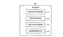
- FIG. 3 is a functional block diagram showing a call processing device as one embodiment of the present invention.
- the call processing device 300 in FIG. 3 corresponds to the call processing server 140 in FIG. 1 and the call processing server 240 in FIG.
- the call processing device 300 includes a transfer source response status monitoring unit 310, an incoming call transfer processing unit 320, a transfer destination response status monitoring unit 330, and an incoming call history deletion request unit 340.
- the transfer source response status monitoring unit 310 responds to an incoming call from the source terminal device (source UE 110 in FIG. 1; source UE 210 in FIG. 2), and the transfer source UE (transfer source in FIG. 1). It is monitored whether the UE 160; the transfer source UE 260 in FIG. 2 has transmitted a response within a predetermined time.
- the time-out monitoring process in step S109 corresponds to the above monitoring.
- the timeout monitoring process in step S209 corresponds to the above monitoring.
- the incoming call transfer processing unit 320 is configured such that the transfer source response status monitoring unit 310 performs a transfer source response to an incoming call from a source terminal device (source UE 110 in FIG. 1; source UE 210 in FIG. 2).
- a source terminal device source UE 110 in FIG. 1; source UE 210 in FIG. 2
- transfer source UE 160 in FIG. 1; transfer source UE 260 in FIG. 2 does not transmit a response within a predetermined time
- an incoming call from the source UE (110; 210) is received. Transfer to the destination UE (160; 260).
- this incoming call transfer process corresponds to the process performed between the transfer information request in step S112 and the call connection response (reception of the response) in step S121.
- this corresponds to the processing performed between the transfer information request in step S212 and the call connection response (reception of the response) in step S222.
- the transfer destination response status monitoring unit 330 transfers a transfer destination terminal device (transfer destination UE 190 in FIG. 1; FIG. 1) to the incoming call from the caller UE (110; 210) transferred by the incoming call transfer processing unit 320.
- the response status of the second transfer destination UE 290) is monitored. This monitoring of the response status corresponds to the monitoring of whether or not a call connection response is received in step 121 in the sequence chart of FIG. Further, in the sequence chart of FIG. 2, the process related to recognition of the call connection response in step S223 corresponds to this.
- the incoming call history deletion request unit 340 receives the incoming call from the source UE (110; 210) transferred by the incoming call transfer processing unit 320 by the transfer destination response status monitoring unit 330. 290) detects that a response indicating that the connection is possible is received, an incoming history deletion request for deleting the incoming history relating to the incoming call for which the response indicating that the connection is possible is detected, and a transfer source UE ( 160; 260).
- This outgoing call history deletion request transmission process corresponds to the incoming call history deletion request in step 125 in the sequence chart of FIG.
- the incoming call history deletion request in step S230 corresponds to this.
- the transfer source response status monitoring unit 310 detects that the transfer source UE 260 has not transmitted a response within a predetermined time, and transfers When it is determined that the original UE 260 is subscribed to the default incoming call transfer service, the default transfer flag indicating that the incoming call is transferred is turned on and managed.
- the transfer source response status monitoring unit 310 In this way, the transfer flag, which was managed by turning it on, is turned off and managed.
- the incoming call history deletion request unit 340 does not issue an incoming call history deletion request to the transfer source terminal device 260 when the transfer flag is off.
- the incoming call history deletion request unit 340 monitors whether or not deletion of the incoming call history in the transfer source UE 160 is completed (step S128). When it is recognized that the deletion of the incoming call history has not been completed, the incoming call history deletion request is repeatedly issued to the transfer source terminal device 160 (step S129).
- the call processing server (call processing device) 240 in the sequence chart of FIG. 2 can be similarly configured.
Landscapes
- Engineering & Computer Science (AREA)
- Signal Processing (AREA)
- Telephonic Communication Services (AREA)
Abstract
発信元(UE110,220)からの着信呼に対して、転送元(UE160,260)が既定時間内に応答を発信していないことを検知したときには、発信元(UE110,220)からの着信呼を転送先(UE190,290)に転送する。また、該転送された発信元からの着信呼に対する、転送先の応答状況(コールバック)を監視する。そして、転送先の端末装置が接続可能の旨の応答をしたことが検知されたときには、転送された着信呼に係る着信履歴を、転送元(UE160,260)において削除させる。
Description
本発明は、着信呼転送サービスの転送元となる端末装置から発信元の端末装置へ無用なコールバックを行ってしまうことを予防する呼処理装置、着信呼転送システム、および、着信履歴取り扱い方法に関する。
近年、発信元の端末装置から或る電話回線を通して着信した通話(着信呼)を別の電話回線に転送する転送電話サービスは、携帯電話であるか固定電話であるかによらず、既によく普及している。
周知の通り、転送電話サービスの一つの利用の態様では、同一ユーザが、転送元とする端末装置と転送先とする端末装置との双方を保有し、或る発信元から転送元への着信呼に応答がない場合に、その着信呼を転送先に転送して、転送先の端末装置からコールバックする(折り返し電話をかける)ことを可能にする。
周知の通り、転送電話サービスの一つの利用の態様では、同一ユーザが、転送元とする端末装置と転送先とする端末装置との双方を保有し、或る発信元から転送元への着信呼に応答がない場合に、その着信呼を転送先に転送して、転送先の端末装置からコールバックする(折り返し電話をかける)ことを可能にする。
一般に、転送電話サービスの機能によって、着信呼が別の電話回線に転送された場合には、転送先の端末装置で上記転送された着信呼に応答したか否かによらず、転送元の端末装置には一律に着信履歴が保持される。
このため、転送元の端末装置における着信履歴を見たユーザが、上記応答済みの用件に関しても、転送元の端末装置から発信元の端末装置にコールバックしてしまうといった無駄な行為を誘発させてしまうおそれがあった。
このため、転送元の端末装置における着信履歴を見たユーザが、上記応答済みの用件に関しても、転送元の端末装置から発信元の端末装置にコールバックしてしまうといった無駄な行為を誘発させてしまうおそれがあった。
尚、転送元の端末装置では呼び出しを行わずに即座に転送してしまう無条件転送サービスの場合は、端末装置に着信履歴が残ることが無い。従って、着信履歴に起因する技術課題は本来的に発生しない技術である。このため、本願における技術とは趣きを異にするものである。
一方、着信履歴に対するコールバックが遅延した場合には、その遅延期間のうちに、コールバックするまでもなく用件は既に解決済みになってしまうことは日常あり得ることである。このような場合、当然ながら、コールバックすることは無駄であり、寧ろ当事者にとって煩わしいだけである。
このような煩わしさに対処すべく、コールバック要請の実行条件を予め規定し、その実行条件を充足する場合に、転送先の端末装置の表示部に発信元の端末装置へのコールバックを要請するメッセージを表示させる技術が提案されている(例えば、特許文献1参照)。
このような煩わしさに対処すべく、コールバック要請の実行条件を予め規定し、その実行条件を充足する場合に、転送先の端末装置の表示部に発信元の端末装置へのコールバックを要請するメッセージを表示させる技術が提案されている(例えば、特許文献1参照)。
特許文献1の技術は、着信呼の転送先の端末装置からの応答の状況を、応答監視部で監視し、この監視の結果、上記実行条件を充足する状況にあると判断された場合に、コールバックを要請するメッセージを着信履歴表示画面に表示させるものである。
しかしながら、特許文献1の技術では、着信呼転送サービスを利用するに際して、転送元に残る着信履歴に起因して、転送元の端末装置からの無用なコールバックを誘発させてしまうことは予防できない。
しかしながら、特許文献1の技術では、着信呼転送サービスを利用するに際して、転送元に残る着信履歴に起因して、転送元の端末装置からの無用なコールバックを誘発させてしまうことは予防できない。
本発明は上述のような状況に鑑みてなされたものであり、着信呼転送サービスを利用する場合における転送元の端末装置に残る着信履歴に起因して、転送元の端末装置からの無用なコールバックを誘発させてしまうおそれを払拭した、呼処理装置、着信呼転送システム、着信履歴取り扱い方法を提供することをその目的とする。
上記課題を解決するために、本発明の一態様は、
発信元の端末装置から転送元の端末装置への着信呼を、転送先の端末装置に転送する、着信呼転送システムに適用される呼処理装置であって、
前記発信元の端末装置からの着信呼に対して、前記転送元の端末装置が既定時間内に応答を発信したか否かを監視する転送元応答状況監視部と、
前記転送元応答状況監視部が、前記発信元の端末装置からの着信呼に対して、前記転送元の端末装置が既定時間内に応答を発信していないことを検知したときには、前記発信元の端末装置からの着信呼を前記転送先の端末装置に転送する着信呼転送処理部と、
前記着信呼転送処理部により転送された、前記発信元の端末装置からの着信呼に対する、前記転送先の端末装置の応答状況を監視する転送先応答状況監視部と、
前記転送先応答状況監視部が、前記着信呼転送処理部によって転送された前記発信元の端末装置からの着信呼に対して、前記転送先の端末装置が接続可能の旨の応答をしたことを検知したときには、前記接続可能の旨の応答が検知された着信呼に係る着信履歴の削除を促す着信履歴削除要求を、前記転送元の端末装置に対して発する着信履歴削除要求部と、を備えていることを特徴とする呼処理装置である。
発信元の端末装置から転送元の端末装置への着信呼を、転送先の端末装置に転送する、着信呼転送システムに適用される呼処理装置であって、
前記発信元の端末装置からの着信呼に対して、前記転送元の端末装置が既定時間内に応答を発信したか否かを監視する転送元応答状況監視部と、
前記転送元応答状況監視部が、前記発信元の端末装置からの着信呼に対して、前記転送元の端末装置が既定時間内に応答を発信していないことを検知したときには、前記発信元の端末装置からの着信呼を前記転送先の端末装置に転送する着信呼転送処理部と、
前記着信呼転送処理部により転送された、前記発信元の端末装置からの着信呼に対する、前記転送先の端末装置の応答状況を監視する転送先応答状況監視部と、
前記転送先応答状況監視部が、前記着信呼転送処理部によって転送された前記発信元の端末装置からの着信呼に対して、前記転送先の端末装置が接続可能の旨の応答をしたことを検知したときには、前記接続可能の旨の応答が検知された着信呼に係る着信履歴の削除を促す着信履歴削除要求を、前記転送元の端末装置に対して発する着信履歴削除要求部と、を備えていることを特徴とする呼処理装置である。
このような構成によれば、転送された着信呼に対して、転送先の端末装置による応答が行われたことが検知されると、この転送された着信呼に係る着信履歴が削除される。このため、無用なコールバックの誘発を予防することができる。
また、前記転送元応答状況監視部は、前記転送元の端末装置が既定時間内に応答を発信していないことを検知し、かつ、前記転送元の端末装置が既定の着信呼転送サービスに加入していると判定したときには、着信呼の転送を行うことを表す既定の転送フラグをオンにして管理し、さらに、前記着信呼転送処理部によって転送された前記発信元の端末装置からの着信呼に対して、前記転送先の端末装置からの応答が接続不可の応答であるときには、前記オンにして管理していた前記転送フラグをオフにして管理し、
前記着信履歴削除要求部は、前記転送フラグがオフであるときには前記着信履歴削除要求を、前記転送元の端末装置に対して発しないものであってもよい。
このような構成によれば、転送フラグの状態に基づく判断によって、着信履歴が存在しない転送元の端末装置に対してまでも、着信履歴削除要求を発してしまうという無駄を無くすことができる。
前記着信履歴削除要求部は、前記転送フラグがオフであるときには前記着信履歴削除要求を、前記転送元の端末装置に対して発しないものであってもよい。
このような構成によれば、転送フラグの状態に基づく判断によって、着信履歴が存在しない転送元の端末装置に対してまでも、着信履歴削除要求を発してしまうという無駄を無くすことができる。
また、前記着信履歴削除要求部は、前記転送元の端末装置における前記着信履歴の削除が完了したか否かを監視し、前記着信履歴の削除が完了していないことを認識したときには、前記転送元の端末装置に対し、前記着信履歴削除要求を繰り返し発するものであってよい。
このような構成によれば、転送元の端末装置における、不要な着信履歴の削除を徹底することができる。
このような構成によれば、転送元の端末装置における、不要な着信履歴の削除を徹底することができる。
本発明の他の態様は、
発信元の端末装置から転送元の端末装置への着信呼を、呼処理装置によって、転送先の端末装置に転送する着信呼転送システムであって、
前記呼処理装置は、
前記発信元の端末装置からの着信呼に対して、前記転送元の端末装置が既定時間内に応答を発信したか否かを監視する転送元応答状況監視部と、
前記転送元応答状況監視部が、前記発信元の端末装置からの着信呼に対して、前記転送元の端末装置が既定時間内に応答を発信していないことを検知したときには、前記発信元の端末装置からの着信呼を前記転送先の端末装置に転送する着信呼転送処理部と、
前記着信呼転送処理部により転送された、前記発信元の端末装置からの着信呼に対する、前記転送先の端末装置の応答状況を監視する転送先応答状況監視部と、
前記転送先応答状況監視部が、前記着信呼転送処理部によって転送された前記発信元の端末装置からの着信呼に対して、前記転送先の端末装置が接続可能の旨の応答をしたことを検知したときには、前記接続可能の旨の応答が検知された着信呼に係る着信履歴の削除を促す着信履歴削除要求を、前記転送元の端末装置に対して発する着信履歴削除要求部と、を備えていることを特徴とする着信呼転送システムである。
発信元の端末装置から転送元の端末装置への着信呼を、呼処理装置によって、転送先の端末装置に転送する着信呼転送システムであって、
前記呼処理装置は、
前記発信元の端末装置からの着信呼に対して、前記転送元の端末装置が既定時間内に応答を発信したか否かを監視する転送元応答状況監視部と、
前記転送元応答状況監視部が、前記発信元の端末装置からの着信呼に対して、前記転送元の端末装置が既定時間内に応答を発信していないことを検知したときには、前記発信元の端末装置からの着信呼を前記転送先の端末装置に転送する着信呼転送処理部と、
前記着信呼転送処理部により転送された、前記発信元の端末装置からの着信呼に対する、前記転送先の端末装置の応答状況を監視する転送先応答状況監視部と、
前記転送先応答状況監視部が、前記着信呼転送処理部によって転送された前記発信元の端末装置からの着信呼に対して、前記転送先の端末装置が接続可能の旨の応答をしたことを検知したときには、前記接続可能の旨の応答が検知された着信呼に係る着信履歴の削除を促す着信履歴削除要求を、前記転送元の端末装置に対して発する着信履歴削除要求部と、を備えていることを特徴とする着信呼転送システムである。
このような構成によれば、その呼処理装置において、転送された着信呼に対して、転送先の端末装置による応答が行われたことが検知されると、この転送された着信呼に係る着信履歴が削除される。このため、無用なコールバックの誘発を予防することができる。
本発明の他の態様は、
発信元の端末装置から転送元の端末装置への着信呼を、転送先の端末装置に転送する際に、前記転送元の端末装置に着信履歴が少なくとも一時的に保持される場合の、着信履歴取り扱い方法であって、
前記発信元の端末装置からの着信呼に対して、前記転送元の端末装置が既定時間内に応答を発信したか否かを監視し、
前記発信元の端末装置からの着信呼に対して、前記転送元の端末装置が既定時間内に応答を発信していないことを検知したときには、前記発信元の端末装置からの着信呼を前記転送先の端末装置に転送し、
前記転送された、前記発信元の端末装置からの着信呼に対する、前記転送先の端末装置の応答状況を監視し、
前記転送された前記発信元の端末装置からの着信呼に対して、前記転送先の端末装置が接続可能の旨の応答をしたことを検知したときには、前記接続可能の旨の応答が検知された着信呼に係る着信履歴の削除を促す着信履歴削除要求を、前記転送元の端末装置に対して発することを特徴とする着信履歴取り扱い方法である。
発信元の端末装置から転送元の端末装置への着信呼を、転送先の端末装置に転送する際に、前記転送元の端末装置に着信履歴が少なくとも一時的に保持される場合の、着信履歴取り扱い方法であって、
前記発信元の端末装置からの着信呼に対して、前記転送元の端末装置が既定時間内に応答を発信したか否かを監視し、
前記発信元の端末装置からの着信呼に対して、前記転送元の端末装置が既定時間内に応答を発信していないことを検知したときには、前記発信元の端末装置からの着信呼を前記転送先の端末装置に転送し、
前記転送された、前記発信元の端末装置からの着信呼に対する、前記転送先の端末装置の応答状況を監視し、
前記転送された前記発信元の端末装置からの着信呼に対して、前記転送先の端末装置が接続可能の旨の応答をしたことを検知したときには、前記接続可能の旨の応答が検知された着信呼に係る着信履歴の削除を促す着信履歴削除要求を、前記転送元の端末装置に対して発することを特徴とする着信履歴取り扱い方法である。
このような構成によれば、転送された着信呼に対して、転送先の端末装置による応答が行われたことを検知したときには、この転送された着信呼に係る着信履歴を削除する。このため、無用なコールバックの誘発を予防することができる。
本発明の一態様によれば、着信呼転送サービスを利用する場合における転送元の端末装置に残る着信履歴に起因して、転送元の端末装置からの無用なコールバックを誘発させてしまうおそれを払拭した、呼処理装置、着信呼転送システム、および、着信履歴取り扱い方法を実現することができる。
以下に、図面を参照して本発明の実施の形態について詳述することにより、本発明を明らかにする。
(着信呼転送システムの一例における構成および動作)
図1は、本願発明の一つの実施の形態としての呼処理装置を含む着信呼転送システムの構成および動作を表すシーケンスチャートである。
(着信呼転送システムの一例における構成および動作)
図1は、本願発明の一つの実施の形態としての呼処理装置を含む着信呼転送システムの構成および動作を表すシーケンスチャートである。
(一例における着信呼転送システムの構成)
図1の実施の形態における着信呼転送システムは、発信元ネットワーク11、転送元ネットワーク12、および、転送先ネットワーク13の各ネットワーク中の、下記の各要素を含んで構成されている。
発信元ネットワーク11は、発信元の端末装置(図中UEと表記)110と、呼処理サーバ120とを含んでいる。
また、転送元ネットワーク12は、顧客管理サーバ130、本発明の実施の形態である呼処理装置としての呼処理サーバ140、音源サーバ150、および、転送元UE160を含んでいる。
さらに、転送先ネットワーク13は、顧客管理サーバ170、呼処理サーバ180、および、転送先UE190を含んでいる。
図1の実施の形態における着信呼転送システムは、発信元ネットワーク11、転送元ネットワーク12、および、転送先ネットワーク13の各ネットワーク中の、下記の各要素を含んで構成されている。
発信元ネットワーク11は、発信元の端末装置(図中UEと表記)110と、呼処理サーバ120とを含んでいる。
また、転送元ネットワーク12は、顧客管理サーバ130、本発明の実施の形態である呼処理装置としての呼処理サーバ140、音源サーバ150、および、転送元UE160を含んでいる。
さらに、転送先ネットワーク13は、顧客管理サーバ170、呼処理サーバ180、および、転送先UE190を含んでいる。
(一例における着信呼転送システムの各要素の機能および動作)
次に、図1のシーケンスチャートを参照して、着信呼転送システムの各要素の機能および動作について説明する。
図1の例における着信呼転送システムでは、上述の転送元UE160および転送先UE190は、着信呼転送サービスに加入している同一のユーザが所有する端末装置である。
尚、上述において、転送元UE160および転送先UE190は、現実の使用時において、同一ユーザが用いることが必須とされるわけではない。即ち、転送元UE160のユーザであり、かつ、転送元UE160への着信呼の転送サービスに加入しているユーザに替えて、他の関連するユーザが転送先UE190の事実上のユーザであるという状況は許容される。
次に、図1のシーケンスチャートを参照して、着信呼転送システムの各要素の機能および動作について説明する。
図1の例における着信呼転送システムでは、上述の転送元UE160および転送先UE190は、着信呼転送サービスに加入している同一のユーザが所有する端末装置である。
尚、上述において、転送元UE160および転送先UE190は、現実の使用時において、同一ユーザが用いることが必須とされるわけではない。即ち、転送元UE160のユーザであり、かつ、転送元UE160への着信呼の転送サービスに加入しているユーザに替えて、他の関連するユーザが転送先UE190の事実上のユーザであるという状況は許容される。
今、他のユーザが発信元UE110から転送元UE160に電話をかけた場合を想定する。
上述の想定においては、先ず、発信元UE110から呼処理サーバ120に通話接続要求が送信される(ステップS101)。
ステップS101での通話接続要求を受けて、呼処理サーバ120は、顧客管理サーバ130に着信先情報の問い合わせを行う(ステップS102)。
上述の想定においては、先ず、発信元UE110から呼処理サーバ120に通話接続要求が送信される(ステップS101)。
ステップS101での通話接続要求を受けて、呼処理サーバ120は、顧客管理サーバ130に着信先情報の問い合わせを行う(ステップS102)。
ステップS102での問い合わせを受けて、顧客管理サーバ130は、呼処理サーバ120に着信先情報を返答する(ステップS103)。
ステップS103での着信先情報を受けて、呼処理サーバ120は、転送元ネットワーク12に設けられた本発明の実施の形態としての呼処理サーバ140に通話接続要求を送信する(ステップS104)。
ステップS103での着信先情報を受けて、呼処理サーバ120は、転送元ネットワーク12に設けられた本発明の実施の形態としての呼処理サーバ140に通話接続要求を送信する(ステップS104)。
ステップS104での通話接続要求を受けて、呼処理サーバ140は、転送元UE160に通話接続要求を送信する(ステップS105)。
呼処理サーバ140は、また、ステップS104での通話接続要求を受けて、音源サーバ150にRBT(リングバックトーン)の送出指示を送る(ステップS106)。
ステップS106でのRBT送出指示を受けて、音源サーバ150は、発信元UE110にRBTを供給する(ステップS107)。
呼処理サーバ140は、また、ステップS104での通話接続要求を受けて、音源サーバ150にRBT(リングバックトーン)の送出指示を送る(ステップS106)。
ステップS106でのRBT送出指示を受けて、音源サーバ150は、発信元UE110にRBTを供給する(ステップS107)。
ここで、先のステップS105での通話接続要求を受けた転送元UE160において、ユーザによる応答操作が無い状況にあるか、或いは、圏外にあって応答できない状況にあるものと想定する。このような状況にあるとき、転送元UE160は、自装置が無応答の状態にあることを認識している(ステップS108)。
転送元UE160がステップS108におけるような無応答の状況にあるとき、呼処理サーバ140は、転送元UE160での無応答の継続時間を計時し、既定の時間を経過しても無応答の状態が継続している場合に、タイムアウトの状態に到ったことを検知する(ステップS109)。上述のようにタイムアウトの状態に到ったということは、転送元UE160への着信呼(ステップS105における通話接続要求)を既定の転送先に転送する契機が到来したことを意味する。
一方、転送元UE160は、ステップS108において自装置が無応答の状況にあることを認識した後、無応答の継続時間を基準に判断する等の自己判断に基づいて、着信呼の転送が起こることを認識し、着信履歴を形成して保持する(ステップS110)。
呼処理サーバ140は、ステップS109でのタイムアウトの検知に次いで、転送元UE160が着信呼転送サービスの正規の加入者であるか否かを判定する(ステップS111)。ここでは、転送元UE160は正規の加入者であり、呼処理サーバ140はその旨を認識するものとする。
呼処理サーバ140は、ステップS109でのタイムアウトの検知に次いで、転送元UE160が着信呼転送サービスの正規の加入者であるか否かを判定する(ステップS111)。ここでは、転送元UE160は正規の加入者であり、呼処理サーバ140はその旨を認識するものとする。
ステップS111で、転送元UE160が正規の加入者であると認識した呼処理サーバ140は、次いで、転送先情報要求を顧客管理サーバ130に送信する(ステップS112)。
ステップS112での転送先情報要求を受けて、顧客管理サーバ130は、着信呼転送サービスの加入契約情報から、転送元UE160に係る転送先情報を検索し、この転送先情報を導出する(ステップS113)。
ステップS112での転送先情報要求を受けて、顧客管理サーバ130は、着信呼転送サービスの加入契約情報から、転送元UE160に係る転送先情報を検索し、この転送先情報を導出する(ステップS113)。
ステップS113で転送元UE160に係る転送先情報を導出すると、顧客管理サーバ130は、その転送先情報を呼処理サーバ140に転送先情報応答として送信する(ステップS114)。
ステップS114での転送先情報を受けて、呼処理サーバ140は、転送先ネットワーク13の顧客管理サーバ170に、着信先情報を問い合せる(ステップS115)。
ステップS114での転送先情報を受けて、呼処理サーバ140は、転送先ネットワーク13の顧客管理サーバ170に、着信先情報を問い合せる(ステップS115)。
ステップS115での着信先情報を問い合せを受けて、顧客管理サーバ170は、呼処理サーバ140に着信先情報を返答する(ステップS116)。
ステップS116での着信先情報の返答を受けて、呼処理サーバ140は、通話接続要求を、転送先ネットワーク13の呼処理サーバ180に送信する(ステップS117)。
ステップS117における通話接続要求は、即ち、転送先への通話接続要求である。そして、ステップS117での通話接続要求は、呼処理サーバ180を介して、転送先のUE190へと送信される(ステップS118)。
ステップS116での着信先情報の返答を受けて、呼処理サーバ140は、通話接続要求を、転送先ネットワーク13の呼処理サーバ180に送信する(ステップS117)。
ステップS117における通話接続要求は、即ち、転送先への通話接続要求である。そして、ステップS117での通話接続要求は、呼処理サーバ180を介して、転送先のUE190へと送信される(ステップS118)。
ステップS118での通話接続要求を受けて、転送先のUE190は、ユーザによる応答操作を待機する(ステップS119)。そして、ユーザによる応答操作があった際に、転送先のUE190は、通話接続応答を、呼処理サーバ180を経て(ステップS120)、転送元ネットワーク12の呼処理サーバ140に送信する(ステップS121)。このステップS120およびステップS121での通話接続応答は、即ち、転送先から発信元UE110への通話接続の要求に対する応答である。
ステップS121での通話接続応答を受けて、呼処理サーバ140は、既述のようにステップS110以降、転送元UE160に保持されている着信履歴を削除すべきと判断する(ステップS122)。
呼処理サーバ140は、また、ステップS121での通話接続応答を受けて、発信元ネットワーク11の呼処理サーバ120を介して(ステップS123)、発信元UE110へと通話接続応答を送信する(ステップS124)。
呼処理サーバ140は、また、ステップS121での通話接続応答を受けて、発信元ネットワーク11の呼処理サーバ120を介して(ステップS123)、発信元UE110へと通話接続応答を送信する(ステップS124)。
一方、転送元ネットワーク12の呼処理サーバ140は、ステップS122での、着信履歴を削除すべき旨の判断に基づいて、転送元UE160に対し、保持されている着信履歴を削除することを促す着信履歴削除要求を送信する(ステップS125)。
ステップS125での着信履歴削除要求を受けて、転送元UE160は、それまで保持していた着信履歴を削除する(ステップS126)。
ステップS125での着信履歴削除要求を受けて、転送元UE160は、それまで保持していた着信履歴を削除する(ステップS126)。
ステップS126での着信履歴の削除処理が完了すると、転送元UE160は、呼処理サーバ140に対し、削除処理完了応答を返す(ステップS127)。
呼処理サーバ140では、転送元UE160における着信履歴の削除処理が完了したか否かを既定の期間継続的に監視し(ステップS128)、削除処理が未完了であると判断したときには、再度、着信履歴削除要求を転送元UE160に送信する(ステップS129)。
呼処理サーバ140では、転送元UE160における着信履歴の削除処理が完了したか否かを既定の期間継続的に監視し(ステップS128)、削除処理が未完了であると判断したときには、再度、着信履歴削除要求を転送元UE160に送信する(ステップS129)。
一方、削除処理完了応答に替えて、着信履歴が元々存在しない旨の応答を受けた場合には、再度、着信履歴削除要求を転送元UE160に送信することなく、処理を終了する。
尚、上述においては、図を参照しての説明の便宜上、ステップS122の着信履歴削除判断以降、発信元UE110への通話接続応答(ステップS123~ステップS124)と、ステップS125の着信履歴削除要求とがタイムシーケンシャルに実行されるが如くに説明した。しかしながら、実際には、上記通話接続応答(ステップS123~ステップS124)と着信履歴削除要求(ステップS125)とは、それらが並行に実行される。
ステップS129以降は、この種の通話システムにおける一般的な通信手順の如く動作する。
尚、上述においては、図を参照しての説明の便宜上、ステップS122の着信履歴削除判断以降、発信元UE110への通話接続応答(ステップS123~ステップS124)と、ステップS125の着信履歴削除要求とがタイムシーケンシャルに実行されるが如くに説明した。しかしながら、実際には、上記通話接続応答(ステップS123~ステップS124)と着信履歴削除要求(ステップS125)とは、それらが並行に実行される。
ステップS129以降は、この種の通話システムにおける一般的な通信手順の如く動作する。
(着信呼転送システムの他の例における構成および動作)
図2は、本願発明の他の実施の形態としての呼処理装置を含む着信呼転送システムの構成および動作を表すシーケンスチャートである。
(他の例における着信呼転送システムの構成)
図2の実施の形態における着信呼転送システムは、発信元ネットワーク21、転送元ネットワーク22、および、転送先ネットワーク23の各ネットワーク中の、下記の各要素を含んで構成されている。
図2は、本願発明の他の実施の形態としての呼処理装置を含む着信呼転送システムの構成および動作を表すシーケンスチャートである。
(他の例における着信呼転送システムの構成)
図2の実施の形態における着信呼転送システムは、発信元ネットワーク21、転送元ネットワーク22、および、転送先ネットワーク23の各ネットワーク中の、下記の各要素を含んで構成されている。
発信元ネットワーク21は、発信元の端末装置(図中UEと表記)210と、呼処理サーバ220とを含んでいる。
また、転送元ネットワーク22は、顧客管理サーバ230、本発明の実施の形態である呼処理装置としての呼処理サーバ240、音源サーバ250、および、転送元UE260を含んでいる。
さらに、転送先ネットワーク23は、顧客管理サーバ270、呼処理サーバ280、および、転送先UE290を含んでいる。
また、転送元ネットワーク22は、顧客管理サーバ230、本発明の実施の形態である呼処理装置としての呼処理サーバ240、音源サーバ250、および、転送元UE260を含んでいる。
さらに、転送先ネットワーク23は、顧客管理サーバ270、呼処理サーバ280、および、転送先UE290を含んでいる。
(他の例における着信呼転送システムの各要素の機能および動作)
次に、図2のシーケンスチャートを参照して、着信呼転送システムの各要素の機能および動作について説明する。
図2の例における着信呼転送システムでは、上述の転送元UE260および転送先UE290は、着信呼転送サービスに加入している同一のユーザが所有する端末装置である。
尚、上述において、転送元UE260および転送先UE290は、現実の使用時において、同ユーザが用いることが必須とされるわけではない。即ち、転送元UE260のユーザであり、かつ、転送元UE260への着信呼の転送サービスに加入しているユーザに替えて、他の関連するユーザが転送先UE290の事実上のユーザであるという状況は許容される。
次に、図2のシーケンスチャートを参照して、着信呼転送システムの各要素の機能および動作について説明する。
図2の例における着信呼転送システムでは、上述の転送元UE260および転送先UE290は、着信呼転送サービスに加入している同一のユーザが所有する端末装置である。
尚、上述において、転送元UE260および転送先UE290は、現実の使用時において、同ユーザが用いることが必須とされるわけではない。即ち、転送元UE260のユーザであり、かつ、転送元UE260への着信呼の転送サービスに加入しているユーザに替えて、他の関連するユーザが転送先UE290の事実上のユーザであるという状況は許容される。
今、他のユーザが発信元UE210から転送元UE260に電話をかけた場合を想定する。
上述の想定においては、先ず、発信元UE210から呼処理サーバ220に通話接続要求が送信される(ステップS201)。
ステップS201での通話接続要求を受けて、呼処理サーバ220は、顧客管理サーバ230に着信先情報の問い合わせを行う(ステップS202)。
上述の想定においては、先ず、発信元UE210から呼処理サーバ220に通話接続要求が送信される(ステップS201)。
ステップS201での通話接続要求を受けて、呼処理サーバ220は、顧客管理サーバ230に着信先情報の問い合わせを行う(ステップS202)。
ステップS202での問い合わせを受けて、顧客管理サーバ230は、呼処理サーバ220に着信先情報を返答する(ステップS203)。
ステップS203での着信先情報を受けて、呼処理サーバ220は、転送元ネットワーク22に設けられた本発明の実施の形態としての呼処理サーバ240に通話接続要求を送信する(ステップS204)。
ステップS203での着信先情報を受けて、呼処理サーバ220は、転送元ネットワーク22に設けられた本発明の実施の形態としての呼処理サーバ240に通話接続要求を送信する(ステップS204)。
ステップS204での通話接続要求を受けて、呼処理サーバ240は、転送元UE260に通話接続要求を送信する(ステップS205)。
呼処理サーバ240は、また、ステップS204での通話接続要求を受けて、音源サーバ250にRBT(リングバックトーン)の送出指示を送る(ステップS206)。
ステップS206でのRBT送出指示を受けて、音源サーバ250は、発信元UE210にRBTを供給する(ステップS207)。
呼処理サーバ240は、また、ステップS204での通話接続要求を受けて、音源サーバ250にRBT(リングバックトーン)の送出指示を送る(ステップS206)。
ステップS206でのRBT送出指示を受けて、音源サーバ250は、発信元UE210にRBTを供給する(ステップS207)。
ここで、先のステップS205での通話接続要求を受けた転送元UE260において、ユーザによる応答操作が無い状況にあるか、或いは、圏外にあって応答できない状況にあるものと想定する。このような状況にあるとき、転送元UE260は、自装置が無応答の状況にあることを認識する(ステップS208)。
転送元UE260がステップS208におけるような状況にあるとき、呼処理サーバ240は、転送元UE260での無応答の時間を計時し、既定の時間を経過しても無応答の状態が継続している場合に、タイムアウトの状態に到ったことを検知する(ステップS209)。上述のようにタイムアウトの状態に到ったということは、転送元UE260への着信呼(ステップS205における通話接続要求)を既定の転送先に転送する契機が到来したことを意味する。
一方、転送元UE260は、ステップS208において自装置が無応答の状況にあることを認識した後、無応答の継続時間を基準に判断する等の自己判断に基づいて、着信呼の転送が起こることを認識し、着信履歴を形成して保持する(ステップS210)。
尚、転送元UE260において、電源をオフにしていることに起因して、結果的に無応答の状況にある場合には、転送元ネットワーク22側において、転送元UE260の電源がオフ状態にあることを認識している。本実施の形態においては、このようにユーザが転送元UE260の電源をオフにしている場合には、転送元ネットワーク22側における、電源オフの旨の認識を反映して、着信履歴を形成しないようにしている。
尚、転送元UE260において、電源をオフにしていることに起因して、結果的に無応答の状況にある場合には、転送元ネットワーク22側において、転送元UE260の電源がオフ状態にあることを認識している。本実施の形態においては、このようにユーザが転送元UE260の電源をオフにしている場合には、転送元ネットワーク22側における、電源オフの旨の認識を反映して、着信履歴を形成しないようにしている。
呼処理サーバ240は、ステップS209でのタイムアウトの検知に次いで、転送元UE260が着信呼転送サービスの正規の加入者であるか否かを判定する(ステップS211)。ここでは、転送元UE260は正規の加入者であり、呼処理サーバ240はその旨を認識するものとする。
ステップS211で、転送元UE260が正規の加入者であると認識した呼処理サーバ240は、次いで、転送先情報要求を顧客管理サーバ230に送信する(ステップS212)。
ステップS211で、転送元UE260が正規の加入者であると認識した呼処理サーバ240は、次いで、転送先情報要求を顧客管理サーバ230に送信する(ステップS212)。
ステップS212での転送先情報要求を受けて、顧客管理サーバ230は、着信呼転送サービスの加入契約情報から、転送元UE260に係る転送先情報を検索し、この転送先情報を導出する(ステップS213)。
ステップS213で転送元UE260に係る転送先情報を導出すると、顧客管理サーバ230は、その転送先情報を呼処理サーバ240に転送先情報応答として送信する(ステップS214)。
ステップS213で転送元UE260に係る転送先情報を導出すると、顧客管理サーバ230は、その転送先情報を呼処理サーバ240に転送先情報応答として送信する(ステップS214)。
呼処理サーバ240が、ステップS214での転送先情報応答を受けた時点では、既に、転送元のUE260が既定時間内に応答を発信せずタイムアウトに到ったことが検知され(上記ステップS209での検知)、かつ、転送元のUE260が既定の着信呼転送サービスの正規の加入者であると判定されている(上記ステップS211での判定)。
呼処理サーバ240では、上述のようにタイムアウトに到ったことが検知され、かつ、転送元のUE260が既定の着信呼転送サービスの正規の加入者であると判定したときには、着信呼の転送を行うことを表す既定の転送フラグをオンにして管理する(ステップS215)。
呼処理サーバ240では、上述のようにタイムアウトに到ったことが検知され、かつ、転送元のUE260が既定の着信呼転送サービスの正規の加入者であると判定したときには、着信呼の転送を行うことを表す既定の転送フラグをオンにして管理する(ステップS215)。
この転送フラグは、呼処理サーバ240における記憶部に保持されて、その状態が管理される。
ステップS215に次いで、呼処理サーバ240は、転送先ネットワーク23の顧客管理サーバ270に、着信先情報を問い合せる(ステップS216)。
ステップS216での着信先情報を問い合せを受けて、顧客管理サーバ270は、呼処理サーバ240に着信先情報を返答する(ステップS217)。
ステップS215に次いで、呼処理サーバ240は、転送先ネットワーク23の顧客管理サーバ270に、着信先情報を問い合せる(ステップS216)。
ステップS216での着信先情報を問い合せを受けて、顧客管理サーバ270は、呼処理サーバ240に着信先情報を返答する(ステップS217)。
ステップS217での着信先情報の返答を受けて、呼処理サーバ240は、通話接続要求を、転送先ネットワーク23の呼処理サーバ280に送信する(ステップS218)。
ステップS218における通話接続要求は、即ち、転送先への通話接続要求である。そして、ステップS218での通話接続要求は、呼処理サーバ280を介して、転送先のUE290へと送信される(ステップS219)。
ステップS218における通話接続要求は、即ち、転送先への通話接続要求である。そして、ステップS218での通話接続要求は、呼処理サーバ280を介して、転送先のUE290へと送信される(ステップS219)。
ステップS219での通話接続要求を受けて、転送先のUE290は、ユーザによる応答操作を待機する(ステップS220)。そして、ユーザによる応答操作があった際に、転送先のUE290は、通話接続応答を、呼処理サーバ280に送る(ステップS221)。
ステップS221での通話接続応答を受けて、呼処理サーバ280は、転送元ネットワーク22の呼処理サーバ240に、通話接続応答を送信する(ステップS222)。このステップS221およびステップS222での通話接続応答は、即ち、転送先から発信元UE210への通話接続の要求に対する応答である。
ステップS221での通話接続応答を受けて、呼処理サーバ280は、転送元ネットワーク22の呼処理サーバ240に、通話接続応答を送信する(ステップS222)。このステップS221およびステップS222での通話接続応答は、即ち、転送先から発信元UE210への通話接続の要求に対する応答である。
このうちステップS222での通話接続応答の内容は、転送先のUE290からの通話接続が可能の旨の応答である場合もあるが、他方、転送先のUE290からの応答が無いままタイムアウトに到った場合などのように通話接続が不可能の旨の応答となる場合もある。
ステップS222での通話接続応答を受けて、呼処理サーバ240は、その通話接続応答があったことを認識する(ステップS223)。
ステップS222での通話接続応答を受けて、呼処理サーバ240は、その通話接続応答があったことを認識する(ステップS223)。
ステップS223で通話接続応答があったことを認識した呼処理サーバ240は、次いで、その通話接続応答の内容が接続可能の旨の応答であるか否かを判断する(ステップS224)。
ステップS224で、通話接続応答の内容が接続不可能の旨の応答であると判断されたときには(ステップS224:No)、ステップS215でオンにして管理していた転送フラグをオフにし(即ち、消去し)、発信元ネットワーク21の呼処理サーバ220に、接続不可能の旨通知する(ステップS225)。
ステップS224で、通話接続応答の内容が接続不可能の旨の応答であると判断されたときには(ステップS224:No)、ステップS215でオンにして管理していた転送フラグをオフにし(即ち、消去し)、発信元ネットワーク21の呼処理サーバ220に、接続不可能の旨通知する(ステップS225)。
ステップS225での接続不可能の旨の通知を受けて、呼処理サーバ220は、発信元のUE210に接続不可能の旨の通知を行う(ステップS226)。
一方、ステップS224で、通話接続応答の内容が接続可能の旨の応答であると判断されたときには(ステップS224:Yes)、呼処理サーバ240は、発信元ネットワーク21に設置された呼処理サーバ220を介して(ステップS227)、発信元のUE210に接続可能の旨の応答を行う(ステップS228)。
一方、ステップS224で、通話接続応答の内容が接続可能の旨の応答であると判断されたときには(ステップS224:Yes)、呼処理サーバ240は、発信元ネットワーク21に設置された呼処理サーバ220を介して(ステップS227)、発信元のUE210に接続可能の旨の応答を行う(ステップS228)。
その後、呼処理サーバ240は、ステップS215でオンにして管理していた転送フラグが未だオン状態であるか否かを確認する(ステップS229)。この確認は、通話接続応答の内容が接続不可能の旨の応答であると判断された場合(ステップS224:No)の処理におけるように、転送フラグが既にオフにされている可能性があるため、転送フラグの現在時点の状態を再確認する趣旨である。
ステップS229での確認の結果、転送フラグが未だオン状態を維持していることが確認されたときには(ステップS229:Yes)、転送元のUE260に対し、着信履歴の削除要求を送信する(ステップS230)。
ステップS230での着信履歴の削除要求を受けて、転送元のUE260では、着信履歴削除処理を実行する(ステップS231)。
ステップS230での着信履歴の削除要求を受けて、転送元のUE260では、着信履歴削除処理を実行する(ステップS231)。
ステップS231の着信履歴削除処理を実行すると、転送元のUE260は、呼処理サーバ240に着信履歴削除完了の応答を返す(ステップS232)。
ステップS232での着信履歴削除完了の応答を受けて、呼処理サーバ240では、転送フラグを削除する。
尚、図1を参照して既述の例と同様に、呼処理サーバ240において、転送元UE260における着信履歴の削除処理が完了したか否かを既定の期間継続的に監視し、削除処理が未完了であると判断したときには、再度、着信履歴削除要求を転送元UE260に送信するように構成してもよい。
ステップS232での着信履歴削除完了の応答を受けて、呼処理サーバ240では、転送フラグを削除する。
尚、図1を参照して既述の例と同様に、呼処理サーバ240において、転送元UE260における着信履歴の削除処理が完了したか否かを既定の期間継続的に監視し、削除処理が未完了であると判断したときには、再度、着信履歴削除要求を転送元UE260に送信するように構成してもよい。
(呼処理装置の構成)
図3は、本願発明の一つの実施の形態としての呼処理装置を表す機能ブロック図である。
図3の呼処理装置300は、図1における呼処理サーバ140、図2における呼処理サーバ240が、それぞれこれに該当する。
呼処理装置300は、転送元応答状況監視部310、着信呼転送処理部320、転送先応答状況監視部330、および、着信履歴削除要求部340を含んで構成されている。
転送元応答状況監視部310は、発信元の端末装置(図1の発信元のUE110;図2の発信元のUE210)からの着信呼に対して、転送元のUE(図1の転送元のUE160;図2の転送元のUE260)が既定時間内に応答を発信したか否かを監視する。
図3は、本願発明の一つの実施の形態としての呼処理装置を表す機能ブロック図である。
図3の呼処理装置300は、図1における呼処理サーバ140、図2における呼処理サーバ240が、それぞれこれに該当する。
呼処理装置300は、転送元応答状況監視部310、着信呼転送処理部320、転送先応答状況監視部330、および、着信履歴削除要求部340を含んで構成されている。
転送元応答状況監視部310は、発信元の端末装置(図1の発信元のUE110;図2の発信元のUE210)からの着信呼に対して、転送元のUE(図1の転送元のUE160;図2の転送元のUE260)が既定時間内に応答を発信したか否かを監視する。
図1のシーケンスチャートではステップS109のタイムアウトの監視処理が上記監視に該当する。また、図2のシーケンスチャートではステップS209のタイムアウトの監視処理が上記監視に該当する。
着信呼転送処理部320は、転送元応答状況監視部310が、発信元の端末装置(図1の発信元のUE110;図2の発信元のUE210)からの着信呼に対して、転送元の端末装置(図1の転送元のUE160;図2の転送元のUE260)が既定時間内に応答を発信していないことを検知したときには、発信元のUE(110;210)からの着信呼を転送先のUE(160;260)に転送する。
着信呼転送処理部320は、転送元応答状況監視部310が、発信元の端末装置(図1の発信元のUE110;図2の発信元のUE210)からの着信呼に対して、転送元の端末装置(図1の転送元のUE160;図2の転送元のUE260)が既定時間内に応答を発信していないことを検知したときには、発信元のUE(110;210)からの着信呼を転送先のUE(160;260)に転送する。
この着信呼の転送処理は、図1のシーケンスチャートでは、ステップS112の転送情報要求から、ステップS121の通話接続応答(その応答の受信)までの間に行われる処理がこれに該当する。また、図2のシーケンスチャートでは、ステップS212の転送情報要求から、ステップS222の通話接続応答(その応答の受信)までの間に行われる処理がこれに該当する。
転送先応答状況監視部330は、着信呼転送処理部320により転送された、発信元のUE(110;210)からの着信呼に対する、転送先の端末装置(図1の転送先のUE190;図2の転送先のUE290)の応答状況を監視する。
この応答状況の監視は、図1のシーケンスチャートでは、ステップ121の通話接続応答の受信の有無の監視がこれに該当する。また、図2のシーケンスチャートでは、ステップS223の通話接続応答の認識に係る処理がこれに該当する。
この応答状況の監視は、図1のシーケンスチャートでは、ステップ121の通話接続応答の受信の有無の監視がこれに該当する。また、図2のシーケンスチャートでは、ステップS223の通話接続応答の認識に係る処理がこれに該当する。
着信履歴削除要求部340は、転送先応答状況監視部330が、着信呼転送処理部320によって転送された発信元のUE(110;210)からの着信呼に対して、転送先のUE(190;290)が接続可能の旨の応答をしたことを検知したときには、該接続可能の旨の応答が検知された着信呼に係る着信履歴の削除を促す着信履歴削除要求を、転送元のUE(160;260)に対して発する。
この着信履歴削除要求の発信処理は、図1のシーケンスチャートでは、ステップ125の着信履歴削除要求がこれに該当する。また、図2のシーケンスチャートでは、ステップS230の着信履歴削除要求がこれに該当する。
図2のシーケンスチャートにおける呼処理サーバ(呼処理装置)240では、その転送元応答状況監視部310において、転送元のUE260が既定時間内に応答を発信していないことを検知し、かつ、転送元のUE260が既定の着信呼転送サービスに加入していると判定したときには、着信呼の転送を行うことを表す既定の転送フラグをオンにして管理する。さらに、着信呼転送処理部320によって転送された発信元のUE210からの着信呼に対して、転送先のUE290からの応答が接続不可の応答であるときには、転送元応答状況監視部310は、上述のようにオンにして管理していた転送フラグをオフにして管理する。
図2のシーケンスチャートにおける呼処理サーバ(呼処理装置)240では、その転送元応答状況監視部310において、転送元のUE260が既定時間内に応答を発信していないことを検知し、かつ、転送元のUE260が既定の着信呼転送サービスに加入していると判定したときには、着信呼の転送を行うことを表す既定の転送フラグをオンにして管理する。さらに、着信呼転送処理部320によって転送された発信元のUE210からの着信呼に対して、転送先のUE290からの応答が接続不可の応答であるときには、転送元応答状況監視部310は、上述のようにオンにして管理していた転送フラグをオフにして管理する。
また、呼処理サーバ(呼処理装置)240では、その着信履歴削除要求部340は、上述の転送フラグがオフであるときには、着信履歴削除要求を、転送元の端末装置260に対して発しない。
一方、図1のシーケンスチャートにおける呼処理サーバ(呼処理装置)140では、その着信履歴削除要求部340において、転送元のUE160における着信履歴の削除が完了したか否かを監視し(ステップS128)、着信履歴の削除が完了していないことを認識したときには、転送元の端末装置160に対し、着信履歴削除要求を繰り返し発する(ステップS129)。この点は、図2のシーケンスチャートにおける呼処理サーバ(呼処理装置)240についても、同様に構成することができることは既述のとおりである。
一方、図1のシーケンスチャートにおける呼処理サーバ(呼処理装置)140では、その着信履歴削除要求部340において、転送元のUE160における着信履歴の削除が完了したか否かを監視し(ステップS128)、着信履歴の削除が完了していないことを認識したときには、転送元の端末装置160に対し、着信履歴削除要求を繰り返し発する(ステップS129)。この点は、図2のシーケンスチャートにおける呼処理サーバ(呼処理装置)240についても、同様に構成することができることは既述のとおりである。
本発明の範囲は、図示され記載された例示的な実施形態に限定されるものではなく、本発明が目的とするものと均等な効果をもたらすすべての実施形態をも含む。さらに、本発明の範囲は、請求項により画される発明の特徴の組み合わせに限定されるものではなく、全ての開示されたそれぞれの特徴のうち特定の特徴のあらゆる所望する組み合わせによって画され得る。
11…………………………………………………………発信元ネットワーク
12…………………………………………………………転送元ネットワーク
13…………………………………………………………転送先ネットワーク
110、210……………………………………………発信元端末装置
120、220……………………………………………呼処理サーバ
130、230……………………………………………顧客管理サーバ
140、240……………………………………………呼処理サーバ
150、250……………………………………………音源サーバ
160、260……………………………………………転送元サーバ
170、270……………………………………………顧客管理サーバ
180、280……………………………………………呼処理サーバ
190、290……………………………………………転送先サーバ
300………………………………………………………呼処理装置
310………………………………………………………着信元応答状況監視部
320………………………………………………………着信呼転送処理部
330………………………………………………………転送先応答状況監視部
340………………………………………………………着信履歴削除要求部
12…………………………………………………………転送元ネットワーク
13…………………………………………………………転送先ネットワーク
110、210……………………………………………発信元端末装置
120、220……………………………………………呼処理サーバ
130、230……………………………………………顧客管理サーバ
140、240……………………………………………呼処理サーバ
150、250……………………………………………音源サーバ
160、260……………………………………………転送元サーバ
170、270……………………………………………顧客管理サーバ
180、280……………………………………………呼処理サーバ
190、290……………………………………………転送先サーバ
300………………………………………………………呼処理装置
310………………………………………………………着信元応答状況監視部
320………………………………………………………着信呼転送処理部
330………………………………………………………転送先応答状況監視部
340………………………………………………………着信履歴削除要求部
Claims (5)
- 発信元の端末装置から転送元の端末装置への着信呼を、転送先の端末装置に転送する、着信呼転送システムに適用される呼処理装置であって、
前記発信元の端末装置からの着信呼に対して、前記転送元の端末装置が既定時間内に応答を発信したか否かを監視する転送元応答状況監視部と、
前記転送元応答状況監視部が、前記発信元の端末装置からの着信呼に対して、前記転送元の端末装置が既定時間内に応答を発信していないことを検知したときには、前記発信元の端末装置からの着信呼を前記転送先の端末装置に転送する着信呼転送処理部と、
前記着信呼転送処理部により転送された、前記発信元の端末装置からの着信呼に対する、前記転送先の端末装置の応答状況を監視する転送先応答状況監視部と、
前記転送先応答状況監視部が、前記着信呼転送処理部によって転送された前記発信元の端末装置からの着信呼に対して、前記転送先の端末装置が接続可能の旨の応答をしたことを検知したときには、前記接続可能の旨の応答が検知された着信呼に係る着信履歴の削除を促す着信履歴削除要求を、前記転送元の端末装置に対して発する着信履歴削除要求部と、を備えていることを特徴とする呼処理装置。 - 前記転送元応答状況監視部は、前記転送元の端末装置が既定時間内に応答を発信していないことを検知し、かつ、前記転送元の端末装置が既定の着信呼転送サービスに加入していると判定したときには、着信呼の転送を行うことを表す既定の転送フラグをオンにして管理し、さらに、前記着信呼転送処理部によって転送された前記発信元の端末装置からの着信呼に対して、前記転送先の端末装置からの応答が接続不可の応答であるときには、前記オンにして管理していた前記転送フラグをオフにして管理し、
前記着信履歴削除要求部は、前記転送フラグがオフであるときには前記着信履歴削除要求を、前記転送元の端末装置に対して発しないことを特徴とする請求項1に記載の呼処理装置。 - 前記着信履歴削除要求部は、前記転送元の端末装置における前記着信履歴の削除が完了したか否かを監視し、前記着信履歴の削除が完了していないことを認識したときには、前記転送元の端末装置に対し、前記着信履歴削除要求を繰り返し発することを特徴とする請求項1または請求項2に記載の呼処理装置。
- 発信元の端末装置から転送元の端末装置への着信呼を、呼処理装置によって、転送先の端末装置に転送する着信呼転送システムであって、
前記呼処理装置は、
前記発信元の端末装置からの着信呼に対して、前記転送元の端末装置が既定時間内に応答を発信したか否かを監視する転送元応答状況監視部と、
前記転送元応答状況監視部が、前記発信元の端末装置からの着信呼に対して、前記転送元の端末装置が既定時間内に応答を発信していないことを検知したときには、前記発信元の端末装置からの着信呼を前記転送先の端末装置に転送する着信呼転送処理部と、
前記着信呼転送処理部により転送された、前記発信元の端末装置からの着信呼に対する、前記転送先の端末装置の応答状況を監視する転送先応答状況監視部と、
前記転送先応答状況監視部が、前記着信呼転送処理部によって転送された前記発信元の端末装置からの着信呼に対して、前記転送先の端末装置が接続可能の旨の応答をしたことを検知したときには、前記接続可能の旨の応答が検知された着信呼に係る着信履歴の削除を促す着信履歴削除要求を、前記転送元の端末装置に対して発する着信履歴削除要求部と、を備えていることを特徴とする着信呼転送システム。 - 発信元の端末装置から転送元の端末装置への着信呼を、転送先の端末装置に転送する際に、前記転送元の端末装置に着信履歴が少なくとも一時的に保持される場合の、着信履歴取り扱い方法であって、
前記発信元の端末装置からの着信呼に対して、前記転送元の端末装置が既定時間内に応答を発信したか否かを監視し、
前記発信元の端末装置からの着信呼に対して、前記転送元の端末装置が既定時間内に応答を発信していないことを検知したときには、前記発信元の端末装置からの着信呼を前記転送先の端末装置に転送し、
前記転送された、前記発信元の端末装置からの着信呼に対する、前記転送先の端末装置の応答状況を監視し、
前記転送された前記発信元の端末装置からの着信呼に対して、前記転送先の端末装置が接続可能の旨の応答をしたことを検知したときには、前記接続可能の旨の応答が検知された着信呼に係る着信履歴の削除を促す着信履歴削除要求を、前記転送元の端末装置に対して発することを特徴とする着信履歴取り扱い方法。
Applications Claiming Priority (2)
| Application Number | Priority Date | Filing Date | Title |
|---|---|---|---|
| JP2011-197585 | 2011-09-09 | ||
| JP2011197585A JP5276148B2 (ja) | 2011-09-09 | 2011-09-09 | 呼処理装置、着信呼転送システム、着信履歴取り扱い方法 |
Publications (1)
| Publication Number | Publication Date |
|---|---|
| WO2013035233A1 true WO2013035233A1 (ja) | 2013-03-14 |
Family
ID=47831714
Family Applications (1)
| Application Number | Title | Priority Date | Filing Date |
|---|---|---|---|
| PCT/JP2012/004565 Ceased WO2013035233A1 (ja) | 2011-09-09 | 2012-07-17 | 呼処理装置、着信呼転送システム、着信履歴取り扱い方法 |
Country Status (2)
| Country | Link |
|---|---|
| JP (1) | JP5276148B2 (ja) |
| WO (1) | WO2013035233A1 (ja) |
Cited By (1)
| Publication number | Priority date | Publication date | Assignee | Title |
|---|---|---|---|---|
| CN105827783A (zh) * | 2015-06-15 | 2016-08-03 | 维沃移动通信有限公司 | 通信记录的处理方法和装置 |
Citations (1)
| Publication number | Priority date | Publication date | Assignee | Title |
|---|---|---|---|---|
| JP2010135899A (ja) * | 2008-12-02 | 2010-06-17 | Hitachi Ltd | 構内交換機 |
Family Cites Families (6)
| Publication number | Priority date | Publication date | Assignee | Title |
|---|---|---|---|---|
| JPH09149452A (ja) * | 1995-11-24 | 1997-06-06 | Nippon Telegr & Teleph Corp <Ntt> | 移動通信装置 |
| JP3336887B2 (ja) * | 1996-12-16 | 2002-10-21 | 株式会社田村電機製作所 | ボタン電話装置 |
| JP4465123B2 (ja) * | 2001-01-18 | 2010-05-19 | 京セラ株式会社 | 通信装置並びに通信装置から情報を入出力するコンピュータ装置及びそのプログラム |
| JP2002271595A (ja) * | 2001-03-12 | 2002-09-20 | Sharp Corp | ファクシミリ装置 |
| JP2002325140A (ja) * | 2001-04-26 | 2002-11-08 | Hitachi Ltd | 携帯端末システム |
| JP2004064662A (ja) * | 2002-07-31 | 2004-02-26 | Nippon Conlux Co Ltd | 情報伝達方法および装置 |
-
2011
- 2011-09-09 JP JP2011197585A patent/JP5276148B2/ja not_active Expired - Fee Related
-
2012
- 2012-07-17 WO PCT/JP2012/004565 patent/WO2013035233A1/ja not_active Ceased
Patent Citations (1)
| Publication number | Priority date | Publication date | Assignee | Title |
|---|---|---|---|---|
| JP2010135899A (ja) * | 2008-12-02 | 2010-06-17 | Hitachi Ltd | 構内交換機 |
Cited By (1)
| Publication number | Priority date | Publication date | Assignee | Title |
|---|---|---|---|---|
| CN105827783A (zh) * | 2015-06-15 | 2016-08-03 | 维沃移动通信有限公司 | 通信记录的处理方法和装置 |
Also Published As
| Publication number | Publication date |
|---|---|
| JP2013058999A (ja) | 2013-03-28 |
| JP5276148B2 (ja) | 2013-08-28 |
Similar Documents
| Publication | Publication Date | Title |
|---|---|---|
| CN101849424B (zh) | 无线通信装置和通信控制方法 | |
| EP1450570B1 (en) | Communication to one mobile station of update of call participation availability status of another mobile station | |
| CN101772946B (zh) | 通信装置、无线通信装置以及通信控制方法 | |
| US20080075258A1 (en) | System and method for preventing spam over internet telephony | |
| US8190568B2 (en) | System and method for providing interactive communications | |
| CN113242583B (zh) | 一种呼叫方法、终端和网络侧设备 | |
| CA2728421C (en) | Intelligent short message delivery system and method | |
| CN101742004A (zh) | 多呼叫中心系统中呼叫转接的方法和装置 | |
| CN103139818A (zh) | 一种aos中保持长连接的方法、系统、aoe、aog及终端 | |
| CN103491512A (zh) | 消息推送的实现方法和装置 | |
| CN103024687A (zh) | 用于建立即时通信的方法和设备 | |
| JP5276148B2 (ja) | 呼処理装置、着信呼転送システム、着信履歴取り扱い方法 | |
| WO2011160378A1 (zh) | 呼叫失败的处理方法及装置 | |
| CN101836485B (zh) | 通信装置和通信控制方法 | |
| CN101730013A (zh) | 一种实现短信自动应答的方法 | |
| CN104333667B (zh) | 一种确定话务状态的方法及装置 | |
| CN101616012A (zh) | 分叉业务处理方法及核心网元 | |
| JP3602512B2 (ja) | 携帯インスタントメッセージサービスシステム及び携帯インスタントメッセージサービスプログラム | |
| KR20070061139A (ko) | Parla y X 웹서비스를 이용한 멀티미디어 메시지서비스 방법 및 장치 | |
| KR100637535B1 (ko) | 불완료 단문메시지 전송 방법 | |
| JP2010206663A (ja) | サーバ装置および取り次ぎシステムおよび取り次ぎ方法 | |
| KR102143771B1 (ko) | D2d 기반 실시간 이동통신단말기 사용상태 확인 시스템 | |
| KR101788836B1 (ko) | 음성호 스팸 차단 장치 및 방법 | |
| JP5717857B2 (ja) | コール転送の宛先の監視 | |
| JP2015139152A (ja) | 相手応答前プレゼンス通知機能を有する呼制御装置 |
Legal Events
| Date | Code | Title | Description |
|---|---|---|---|
| 121 | Ep: the epo has been informed by wipo that ep was designated in this application |
Ref document number: 12829315 Country of ref document: EP Kind code of ref document: A1 |
|
| NENP | Non-entry into the national phase |
Ref country code: DE |
|
| 122 | Ep: pct application non-entry in european phase |
Ref document number: 12829315 Country of ref document: EP Kind code of ref document: A1 |