WO2013031256A1 - 経路維持部材付コルゲートチューブ及びワイヤーハーネス - Google Patents
経路維持部材付コルゲートチューブ及びワイヤーハーネス Download PDFInfo
- Publication number
- WO2013031256A1 WO2013031256A1 PCT/JP2012/053913 JP2012053913W WO2013031256A1 WO 2013031256 A1 WO2013031256 A1 WO 2013031256A1 JP 2012053913 W JP2012053913 W JP 2012053913W WO 2013031256 A1 WO2013031256 A1 WO 2013031256A1
- Authority
- WO
- WIPO (PCT)
- Prior art keywords
- wire harness
- corrugated tube
- path
- branch
- maintaining
- Prior art date
- Legal status (The legal status is an assumption and is not a legal conclusion. Google has not performed a legal analysis and makes no representation as to the accuracy of the status listed.)
- Ceased
Links
Images


Classifications
-
- H—ELECTRICITY
- H02—GENERATION; CONVERSION OR DISTRIBUTION OF ELECTRIC POWER
- H02G—INSTALLATION OF ELECTRIC CABLES OR LINES, OR OF COMBINED OPTICAL AND ELECTRIC CABLES OR LINES
- H02G3/00—Installations of electric cables or lines or protective tubing therefor in or on buildings, equivalent structures or vehicles
- H02G3/02—Details
- H02G3/04—Protective tubing or conduits, e.g. cable ladders or cable troughs
- H02G3/0462—Tubings, i.e. having a closed section
- H02G3/0468—Corrugated
-
- B—PERFORMING OPERATIONS; TRANSPORTING
- B60—VEHICLES IN GENERAL
- B60R—VEHICLES, VEHICLE FITTINGS, OR VEHICLE PARTS, NOT OTHERWISE PROVIDED FOR
- B60R16/00—Electric or fluid circuits specially adapted for vehicles and not otherwise provided for; Arrangement of elements of electric or fluid circuits specially adapted for vehicles and not otherwise provided for
Definitions
- This invention relates to a technique for keeping the path constant while covering the branch portion of the wire harness.
- Patent Documents 1 to 4 a technique of covering a wire harness laid on a vehicle or the like with a corrugated tube having good flexibility is known.
- the corrugated tube itself is excellent in flexibility, the corrugated tube itself does not have a function of maintaining the wire harness path constant. For this reason, it is necessary to maintain the path
- the path can be maintained constant while protecting the wire harness.
- the inventors of the present application attach a path maintaining member molded to maintain a constant shape along the longitudinal direction to the corrugated tube, and maintain the corrugated tube and the internal wire harness in a fixed shape.
- a configuration for attaching the path maintaining member to the corrugated tube a configuration has been proposed in which a pair of concave grooves are formed in the path maintaining member, and edge portions on both sides of the slit of the corrugated tube are fitted into the pair of concave grooves. .
- a plurality of electric wires are usually bundled so as to branch.
- the path maintaining member is formed to branch in multiple directions.
- the present invention attaches a path maintaining member to the corrugated tube, thereby easily forming the path maintaining member when maintaining the branch direction constant while covering the peripheral part of the branch part of the wire harness main body part.
- the purpose is to be able to.
- the first aspect covers a plurality of wire harness branch extending portions extending from the branch portion of the wire harness main body portion, and has a constant path for each of the plurality of wire harness branch extending portions.
- a corrugated tube, a block-like portion, and a plurality of path maintenance extending portions extending from the block-like portion, and each of the plurality of path maintenance extending portions maintains a constant shape along the longitudinal direction.
- Both sides of the slit of one of the plurality of corrugated tubes are formed in each of the plurality of path maintaining extension portions and formed in a possible long portion.
- a pair of recessed groove portion which edge portion is accommodated is formed, and a route maintenance member.
- the second aspect is a corrugated tube with a path maintaining member according to the first aspect, wherein the block-like portion is formed in a spherical or rectangular parallelepiped shape.
- a 3rd aspect is a corrugated tube with a path
- the said block-shaped part is a three-dimensional extension area
- a fourth aspect includes a corrugated tube with a path maintaining member according to any one of the first to third aspects, and a plurality of wire harness branch extending portions in which a plurality of electric wires extend from the branch portion and the branch portion. And a wire harness main body portion in which each of the plurality of wire harness branch extending portions is inserted into each of the plurality of corrugated tubes.
- the wire harness branch extending portion that is the peripheral portion of the branch portion of the wire harness main body portion is provided. Can be covered.
- the wire harness branch extending by the path maintaining extension part The branch direction of the part can be kept constant.
- route maintenance member is simplified and a path
- the block-shaped portion is formed in a spherical or rectangular parallelepiped shape, a path maintaining member can be easily formed.
- the block-shaped portion is formed in a shape including a three-dimensional overlapping area of the extension area to the inside of the plurality of path maintaining extension portions, and therefore, the plurality of path maintaining extensions. Locations where the protruding portions are intertwined in a complicated manner can be suppressed, and the path maintaining member can be formed more easily.
- the wire harness branch extension part which is a peripheral part of the branch part of a wire harness main-body part can be covered by coat
- the wire harness branch extending by the path maintaining extension part The branch direction of the part can be kept constant.
- route maintenance member is simplified and a path
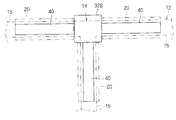
- FIG. 1 is a schematic plan view showing a mounting portion of the corrugated tube 20 in the wire harness 10
- FIG. 2 is a schematic perspective view showing a part of the corrugated tube 20 attached with a route maintaining member 30
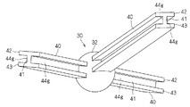
- FIG. 3 is a schematic perspective view showing a member 30.
- the wire harness 10 is attached to the periphery of the branching portion 14 of the wire harness main body 12 and includes the wire harness main body 12, the corrugated tube 20, and the path maintaining member 30.
- the wire harness main body 12 has a configuration in which a plurality of electric wires are bundled while branching according to a wiring form to a vehicle to be arranged.
- a portion where a plurality of electric wires are bundled so as to branch into three that is, a portion where three wire harness branch extending portions 15 extend from the branch portion 14 will be described.
- the location bound so that a some electric wire may branch into four or more may be sufficient.
- another optical cable or the like may be bound to the wire harness main body 12.
- the wire harness main body 12 When the wire harness main body 12 is disposed in a vehicle or the like, the wire harness main body 12 is routed along the arrangement form. In order to prevent the wire harness body 12 from interfering with the peripheral portion, etc., the extension direction of each wire harness branch extension 15 from the branch 14 is kept constant in the vicinity of the branch 14. There is. Moreover, the wire harness main-body part 12 may be maintained in the shape along the wiring form. In such a case, the corrugated tube C with a path maintaining member is attached to the periphery of the branching portion 14 in the wire harness main body 12 and maintains the extending direction of each wire harness branch extending portion 15 constant. Moreover, this corrugated tube C with a path
- the corrugated tube 20 is a cylindrical member in which annular convex portions 21 and annular concave portions 22 are alternately formed along the longitudinal direction (see FIG. 2), and is formed of a resin or the like. Since the corrugated tube 20 is easily elastically deformed at a step portion between the annular convex portion 21 and the annular concave portion 22, the corrugated tube 20 itself has a property of being easily bent and deformed as a whole. Normally, as the corrugated tube 20, a tube having an inner diameter larger than the outer diameter of the portion of the wire harness branch extending portion 15 to be mounted (usually somewhat larger) is used, and the wire harness branch extending inside the corrugated tube 20 is used. The portion 15 can be disposed.
- a slit 24 is formed on one side of the corrugated tube 20 along the longitudinal direction thereof.
- the wire harness branch extending portion 15 can be easily disposed in the corrugated tube 20 so as to be opened by the slit 24.
- the corrugated tube 20 is used corresponding to the three wire harness branching extension portions 15. As each corrugated tube 20, it is good to use the thing according to the diameter of the wire harness branch extension part 15 used as an accommodation aspect, respectively.
- the route maintaining member 30 includes a block-shaped portion 32 and a plurality of route maintaining extending portions 40.
- the block-shaped portion 32 is formed in a block shape having no dent, for example, a spherical shape and a polyhedral shape (including those obtained by rounding sides and corners).
- the block-shaped part 32 is formed in a spherical shape.
- the block-shaped portion 32 has a three-dimensional overlapping area (in the plan view of FIG. 1) of the extending area to the inside of the plurality of route maintaining / extending portions 40. It is preferably formed in a shape including a hatched area A). That is, assuming a spatial area in which each path maintaining extension 40 is extended toward the block-shaped portion 32 side, the block-shaped portion 32 is large enough to include an area A where all the spatial areas overlap. It is preferable that it is set. Also in this embodiment, the block-shaped portion 32 is formed in a spherical shape having a diameter larger than that of the area A.
- the plurality of route maintenance extending portions 40 are formed so as to extend from the block-shaped portion 32.
- the two path maintaining extension portions 40 extend outward from both side portions of the block-like portion 32 (see FIGS. 1 and 3).
- one path maintaining extension 40 extends from the block-shaped portion 32 in a direction orthogonal to the two path maintaining extensions 40 (see FIGS. 1 and 3).
- the extension direction of each path maintenance extension part 40 is an example, and it is only necessary to extend in different directions. Also, the postures around the central axis of each path maintaining extension 40 may be different from each other.
- the block-shaped portion 32 is formed in a size including the area A, the plurality of path maintenance extending portions 40 do not intersect directly with each other in the block-shaped portion 32. Therefore, it is possible to suppress the places where the uneven portions of each path maintaining extension 40 are intricately mixed, and the shape of the intersection of each path maintaining extension 40 can be simplified.
- Each path maintenance extension part 40 is formed in the long part which can maintain a fixed shape along the longitudinal direction, respectively.
- each of the route maintaining extension portions 40 is connected to the P.A. P. It is integrally molded with a resin such as (polypropylene). Therefore, at the time of mold forming, the path maintaining extension 40 is formed in a straight line shape or a shape in which at least a part thereof is bent, and the wire harness branch extension 15 can be maintained along a certain path. Has high rigidity.
- the path maintaining extension 40 formed in a straight line is shown, but at least one of the path maintaining extension 40 is molded into a shape bent at least partially. It may be.
- each path maintenance extending part 40 has a part in which a pair of concave groove parts 44g capable of accommodating the edge parts on both sides of the slit 24 in the corrugated tube 20 are formed.
- the path maintaining extension part 40 is provided with the outer peripheral projection 42 on the one side (outer peripheral side) edge of the long connecting part 41 and the other side (inner peripheral side) of the connecting part 41.
- the inner peripheral projection 43 is provided at the edge, and the cross-sectional shape of the surface orthogonal to the longitudinal direction is substantially H-shaped.
- the width dimension of the recessed groove 44g is the thickness dimension of the corrugated tube 20 (more specifically, the difference between the outermost peripheral portion of the annular convex portion 21 and the innermost peripheral portion of the annular concave portion 22 in the radial direction of the corrugated tube 20).
- the dimensions are set to be approximately the same or larger (slightly larger).
- the depth dimension of the concave groove 44g is not particularly limited as long as it can be accommodated in a state where the end edge of the corrugated tube 20 is positioned to some extent in the radial direction.
- the part of the path maintaining extension 40 where the pair of concave grooves 44g are formed may be the entire longitudinal direction of the path maintaining extension 40 or a part along the longitudinal direction. Also good. In the present embodiment, an example in which a pair of concave groove portions 44g are formed over the entire longitudinal direction of the path maintaining extension portion 40 will be described.
- the corrugated tube 20 is opened by the slit 24 around the branching portion 14 of the wire harness main body 12 so that the wire harness branch extending portion 15 of the wire harness main body 12 is accommodated in the corrugated tube 20 in an insertion shape. .
- the corrugated tube 20 is also attached to the other wire harness branch extension 15.
- the path maintaining extension 40 is disposed around the branching portion 14 of the wire harness main body 12 so that each path maintaining extending section 40 is disposed along the wire harness branch extending section 15.
- the corrugated tube 20 is opened with the slit 24, and the edge part of the both sides of the slit 24 among the corrugated tubes 20 is engage
- the connecting portion 41 is disposed in the slit 24, the outer peripheral projection 42 is disposed outside the slit 24 along the outer peripheral surface of the corrugated tube 20, and the inner peripheral projection 43 is the slit 24. It is arranged along the inner peripheral surface of the corrugated tube 20 on the inner side.
- a tie band, an adhesive tape or the like is wound around the outer periphery of the corrugated tube 20 so that the closed state of the corrugated tube 20 is maintained, and the corrugated tube 20 and the path maintaining extension 40 are integrated.
- the route maintaining member 30 is attached to the wire harness main body 12.
- the corrugated tube C with a path maintaining member and the wire harness 10 configured as described above, by surrounding the corrugated tube 20 on the wire harness branch extending portion 15, the peripheral portion of the branch portion 14 of the wire harness main body portion 12. It is possible to cover and protect the wire harness branch extending portion 15. Further, by attaching the path maintaining extension 40 to the corrugated tube 20 so that the edge portions on both sides of the slit 24 of the corrugated tube 20 are accommodated in the pair of concave grooves 44g, the path maintaining extending section 40 The branch direction of the wire harness branch extension 15 can be maintained constant. Moreover, the wire harness branch extension part 15 can be maintained in a fixed shape (here, constant in a straight line shape) along the longitudinal direction by the shape of the path maintaining extension part 40.
- the shape of the intersecting portion of each wire harness branch extending portion 15 can be simplified.
- the shape of the block-shaped portion 32 can be more reliably formed. It can be simplified.
- the block-shaped portion 32 may have another spherical shape.
- the block-shaped part 32B corresponding to the block-shaped part 32 may be formed in a rectangular parallelepiped (here, a cube) shape.
- each path maintaining extension 40 extends from any surface of the block-like portion 32.
Landscapes
- Engineering & Computer Science (AREA)
- Mechanical Engineering (AREA)
- Architecture (AREA)
- Civil Engineering (AREA)
- Structural Engineering (AREA)
- Details Of Indoor Wiring (AREA)
- Insulated Conductors (AREA)
Abstract
コルゲートチューブに経路維持部材を取付けることによって、ワイヤーハーネス本体部の分岐部の周辺部を覆いつつそれらの分岐方向を一定に維持する際に、経路維持部材の形成を容易にできるようにすることを目的とする。経路維持延出部付コルゲートチューブは、ワイヤーハーネス本体部の分岐部の周辺に取付けられる。経路維持延出部付コルゲートチューブは、コルゲートチューブと、経路維持部材とを備える。経路維持部材は、ブロック状部分と、ブロック状部分から延出する複数の経路維持延出部とを備えている。経路維持延出部は、長手方向に沿って一定の形状を維持可能な長尺部分に形成されている。経路維持延出部には、コルゲートチューブのスリットの両側の端縁部が収容される一対の凹溝部が形成されている。
Description
この発明は、ワイヤーハーネスの分岐部を覆いつつその経路を一定に維持する技術に関する。
従来より、特許文献1~4に開示のように、車両等に敷設されるワイヤーハーネスを、屈曲性良好なコルゲートチューブにて覆う技術が知られている。
しかしながら、コルゲートチューブ自体は、屈曲性に優れるもの故、それ自体はワイヤーハーネスの経路を一定に維持する機能を持たない。このため、ワイヤーハーネス或はコルゲートチューブに取付けられたクランプ部材を車両の一定位置に固定することで、ワイヤーハーネスの経路を一定に維持する必要がある。クランプ部材の固定箇所が多くなると、部品コスト増、取付けコスト増等を招く恐れがある。
ここで、ワイヤーハーネスの敷設箇所に合わせた形状に形成した樋状の樹脂成型品(プロテクタ)によれば、ワイヤーハーネスを保護しつつその経路を一定に維持することができる。
しかしながら、ワイヤーハーネスを保護可能な樹脂成型品を、ワイヤーハーネスの敷設箇所に合わせて3次元形状等の複雑な形成するためには、その金型形状が複雑化してしまう。このため、製造コストが高くなる。
そこで、本願発明者らによって、コルゲートチューブに、長手方向に沿って一定形状を維持するように金型成型された経路維持部材を取付けて、コルゲートチューブ及び内部のワイヤーハーネスを一定形状に維持する構成が提案されている。経路維持部材をコルゲートチューブに取付ける構成としては、経路維持部材に一対の凹溝部を形成し、コルゲートチューブのうちスリットの両側の端縁部を前記一対の凹溝部に嵌め込む構成が提案されている。
ところで、ワイヤーハーネスでは、通常、複数の電線が分岐するように束ねられている。ワイヤーハーネスの分岐部を所定の分岐方向に沿って維持するためには、経路維持部材を多方向に分岐するように形成することになる。
しかしながら、経路維持部材には一対の凹溝部が形成されているため、分岐部で形状が複雑となる。このため、経路維持部材を金型成型等することが困難となる。
そこで、本発明は、コルゲートチューブに経路維持部材を取付けることによって、ワイヤーハーネス本体部の分岐部の周辺部を覆いつつそれらの分岐方向を一定に維持する際に、経路維持部材の形成を容易にできるようにすることを目的とする。
上記課題を解決するため、第1の態様は、ワイヤーハーネス本体部の分岐部から延出する複数のワイヤーハーネス分岐延出部を覆うと共にそれぞれの前記複数のワイヤーハーネス分岐延出部の経路を一定に維持するための経路維持部材付コルゲートチューブであって、それぞれ前記複数のワイヤーハーネス分岐延出部のうちの1つを挿通可能で、かつ、それぞれの長手方向に沿ってスリットが形成された複数のコルゲートチューブと、ブロック状部分と、前記ブロック状部分から延出する複数の経路維持延出部とを有し、前記複数の経路維持延出部がそれぞれ長手方向に沿って一定の形状を維持可能な長尺部分に形成されると共に、前記複数の経路維持延出部のそれぞれに前記複数のコルゲートチューブのうちの1つの前記スリットの両側の端縁部が収容される一対の凹溝部が形成された、経路維持部材とを備える。
第2の態様は、第1の態様に係る経路維持部材付コルゲートチューブであって、前記ブロック状部分は、球状又は直方体状に形成されている。
第3の態様は、第1又は第2の態様に係る経路維持部材付コルゲートチューブであって、前記ブロック状部分は、前記複数の経路維持延出部の内側への延長エリアの3次元的な重複エリアを包含する形状に形成されている。
第4の態様は、第1~第3のいずれか1つの態様に係る経路維持部材付コルゲートチューブと、複数の電線が、分岐部と前記分岐部から延出する複数のワイヤーハーネス分岐延出部とを有する形態に束ねられ、前記複数のワイヤーハーネス分岐延出部のそれぞれが前記複数のコルゲートチューブのそれぞれに挿通されている、ワイヤーハーネス本体部とを備える。
第1の態様に係る経路維持部材付コルゲートチューブによると、各コルゲートチューブをワイヤーハーネス分岐延出部に外装することによって、ワイヤーハーネス本体部の分岐部の周辺部であるワイヤーハーネス分岐延出部を覆うことができる。また、各コルゲートチューブのスリットの両側の端縁部を一対の凹溝部に収容するようにして、経路維持延出部をコルゲートチューブに取付けることによって、当該経路維持延出部によってワイヤーハーネス分岐延出部の分岐方向を一定に維持できる。また、複数のワイヤーハーネス分岐延出部は、ブロック状部分から延出しているため、経路維持部材の形状が簡素化され、経路維持部材を容易に形成できる。
第2の態様によると、前記ブロック状部分は、球状又は直方体状に形成されているため、経路維持部材を容易に形成できる。
第3の態様によると、前記ブロック状部分は、前記複数の経路維持延出部の内側への延長エリアの3次元的な重複エリアを包含する形状に形成されているため、複数の経路維持延出部同士が複雑に絡み合う箇所を抑制することができ、経路維持部材をより容易に形成できる。
第4の態様に係るワイヤーハーネスによると、各コルゲートチューブをワイヤーハーネス分岐延出部に外装することによって、ワイヤーハーネス本体部の分岐部の周辺部であるワイヤーハーネス分岐延出部を覆うことができる。また、各コルゲートチューブのスリットの両側の端縁部を一対の凹溝部に収容するようにして、経路維持延出部をコルゲートチューブに取付けることによって、当該経路維持延出部によってワイヤーハーネス分岐延出部の分岐方向を一定に維持できる。また、複数のワイヤーハーネス分岐延出部は、ブロック状部分から延出しているため、経路維持部材の形状が簡素化され、経路維持部材を容易に形成できる。
以下、実施形態に係るワイヤーハーネス及び経路維持部材付コルゲートチューブについて説明する。図1はワイヤーハーネス10のうちコルゲートチューブ20の装着部分を示す概略平面図であり、図2はコルゲートチューブ20に経路維持部材30を取付けた一部分を示す概略斜視図であり、図3は経路維持部材30を示す概略斜視図である。
このワイヤーハーネス10は、ワイヤーハーネス本体部12の分岐部14の周辺部に装着されるものであり、ワイヤーハーネス本体部12と、コルゲートチューブ20と、経路維持部材30とを備える。
ワイヤーハーネス本体部12は、複数の電線が配設対象となる車両への配線形態に応じて分岐しつつ結束された構成とされている。本実施形態では、複数の電線が3つに分岐するように結束された箇所、即ち、分岐部14から3つのワイヤーハーネス分岐延出部15が延出する箇所に適用した例で説明する。もっとも、複数の電線が4つ以上に分岐するように結束された箇所であってもよい。また、ワイヤーハーネス本体部12に、他の光ケーブル等が結束されていてもよい。
上記ワイヤーハーネス本体部12を、車両等に配設する際、ワイヤーハーネス本体部12はその配設形態に沿って配索される。ワイヤーハーネス本体部12が周辺部分に干渉すること等を抑制するため、分岐部14の周辺においては、分岐部14からの各ワイヤーハーネス分岐延出部15の延出方向が一定に維持されることがある。また、ワイヤーハーネス本体部12はその配線形態に沿った形状に維持されることがある。このような場合に、本経路維持部材付コルゲートチューブCがワイヤーハーネス本体部12のうち上記分岐部14の周辺に装着され、各ワイヤーハーネス分岐延出部15の延出方向を一定に維持する。また、本経路維持部材付コルゲートチューブCは、各ワイヤーハーネス分岐延出部15を一定の形状に維持することもできる。なお、ワイヤーハーネス本体部12に対して本経路維持部材付コルゲートチューブCが装着される部分は、ワイヤーハーネス本体部12の分岐部14周辺の少なくとも一部であればよい。
コルゲートチューブ20は、長手方向に沿って環状凸部21と環状凹部22とが交互に形成された筒状部材であり(図2参照)、樹脂等で形成されている。かかるコルゲートチューブ20は、環状凸部21と環状凹部22との間の段部等で容易に弾性変形するため、それ自体では全体として曲げ変形容易な性質を有している。通常、コルゲートチューブ20としては、装着対象となるワイヤーハーネス分岐延出部15の部分の外径よりも大きい(通常は多少大きい程度)内径を有するものが用いられ、その内部にワイヤーハーネス分岐延出部15を配設できるようになっている。
また、コルゲートチューブ20の一側部にその長手方向に沿ってスリット24が形成されている。そして、当該スリット24で割開くようにして、ワイヤーハーネス分岐延出部15をコルゲートチューブ20内に容易に配設できるようになっている。
ここでは、上記3つのワイヤーハーネス分岐延出部15に対応してコルゲートチューブ20が用いられる。各コルゲートチューブ20としては、それぞれ収容態様となるワイヤーハーネス分岐延出部15の径に応じたものを用いるとよい。
経路維持部材30は、ブロック状部分32と、複数の経路維持延出部40とを備えている。
ブロック状部分32は、凹みが無いブロック形状、例えば、球状、多面体形状(辺、角を丸め処理したものを含む)に形成されている。ここでは、ブロック状部分32は、球状に形成されている。
複数の経路維持延出部40との関係でいうと、ブロック状部分32は、複数の経路維持延出部40の内側への延出エリアの3次元的な重複エリア(図1の平面図で斜線を付したエリアA参照)を包含する形状に形成されていることが好ましい。つまり、各経路維持延出部40をブロック状部分32側に向けて延出させた空間エリアを想定すると、ブロック状部分32は、各空間エリアの全てが重複するエリアAを包含するような大きさに設定されていることが好ましい。本実施形態でも、ブロック状部分32は、前記エリアAよりも大きな直径の球状に形成されている。
複数の経路維持延出部40は、上記ブロック状部分32から延出するように形成されている。ここでは、平面視において、2つの経路維持延出部40は、ブロック状部分32の両側部から外方に向けて延出している(図1、図3参照)。また、平面視において、1つの経路維持延出部40は、ブロック状部分32から前記2つの経路維持延出部40に対して直交する方向に延出している(図1、図3参照)。各経路維持延出部40の上記延出方向は、一例であり、それぞれ異なる方向に延出していればよい。また、各経路維持延出部40の中心軸周りの姿勢も相互に別々の姿勢であってもよい。
上記したように、ブロック状部分32は、エリアAを含む大きさに形成されているため、複数の経路維持延出部40は、ブロック状部分32において直接交わらない。従って、各経路維持延出部40の凹凸部分が複雑に入交じる箇所を抑制することができ、各経路維持延出部40の交差部分の形状を単純化することができる。
各経路維持延出部40は、それぞれ長手方向に沿って一定の形状を維持可能な長尺部分に形成されている。ここでは、各経路維持延出部40は、ブロック状部分32と共に、P.P.(ポリプロピレン)等の樹脂によって一体に金型成型されている。従って、金型成型時点で、経路維持延出部40は、直線状或は少なくとも一部が曲げられた形状に形成され、また、ワイヤーハーネス分岐延出部15を一定の経路に沿って維持可能な剛性を有している。ここでは、図1及び図3では、直線状に形成された経路維持延出部40を示しているが、経路維持延出部40の少なくとも1つが少なくとも一部で曲げた形状に金型成型されていてもよい。
また、各経路維持延出部40には、コルゲートチューブ20のうちスリット24の両側の端縁部を収容可能な一対の凹溝部44gが形成された部分を有している。換言すれば、経路維持延出部40は、長尺状の連結部41の一方側(外周側)縁部に外周側突起部42が設けられると共に、連結部41の他方側(内周側)縁部に内周側突起部43が設けられた構成され、その長手方向に対して直交する面における断面形状が略H字状を呈している。凹溝部44gの幅寸法は、コルゲートチューブ20の厚み寸法(より具体的には、コルゲートチューブ20の径方向において環状凸部21の最外周部分と環状凹部22の最内周部分との差)と略同じかそれよりも大きい(僅かに大きい)程度の寸法に設定されている。凹溝部44gの深さ寸法は、コルゲートチューブ20の端縁部をその径方向にある程度位置決めした状態で収容できる程度であればよく、特に限定はない。
上記経路維持延出部40のうち上記一対の凹溝部44gが形成された部分は、経路維持延出部40の長手方向全体であってもよいし、その長手方向に沿った一部であってもよい。本実施形態では、一対の凹溝部44gが経路維持延出部40の長手方向全体に亘って形成された例で説明する。
上記経路維持部材30をワイヤーハーネス本体部12の分岐部14の周辺に取付ける作業手順について説明する。
まず、ワイヤーハーネス本体部12の分岐部14周辺において、コルゲートチューブ20を前記スリット24で開くことで、コルゲートチューブ20内にワイヤーハーネス本体部12のワイヤーハーネス分岐延出部15を挿通状に収容する。同様にして、他のワイヤーハーネス分岐延出部15にもコルゲートチューブ20を装着する。
そして、各経路維持延出部40をワイヤーハーネス分岐延出部15に沿って配設するようにして、経路維持延出部40をワイヤーハーネス本体部12の分岐部14周辺に配設する。そして、各ワイヤーハーネス分岐延出部15において、コルゲートチューブ20をスリット24で開いて、コルゲートチューブ20のうちスリット24の両側の端縁部を一対の凹溝部44g内に嵌め込む。この状態では、連結部41がスリット24内に配設され、外周側突起部42がスリット24の外側でコルゲートチューブ20の外周面に沿って配設され、内周側突起部43がスリット24の内側でコルゲートチューブ20内周面に沿って配設される。これにより、各コルゲートチューブ20及び内部のワイヤーハーネス分岐延出部15は、経路維持延出部40の延出方向に沿って一定形状に維持された状態で、当該経路維持延出部40と一体化されることとなる。
この後、必要に応じて、タイバンド、粘着テープ等がコルゲートチューブ20の外周に巻付けられ、コルゲートチューブ20の閉状態が維持されると共に、コルゲートチューブ20と経路維持延出部40との一体化状態が維持され、経路維持部材30がワイヤーハーネス本体部12に取付けられる。
以上のように構成された経路維持部材付コルゲートチューブC及びワイヤーハーネス10によると、コルゲートチューブ20をワイヤーハーネス分岐延出部15に外装することによって、ワイヤーハーネス本体部12の分岐部14の周辺部であるワイヤーハーネス分岐延出部15を覆って保護することができる。また、コルゲートチューブ20のスリット24の両側の端縁部を一対の凹溝部44gに収容するようにして、経路維持延出部40をコルゲートチューブ20に取付けることによって、当該経路維持延出部40によりワイヤーハーネス分岐延出部15の分岐方向を一定に維持できる。また、経路維持延出部40の形状によって、ワイヤーハーネス分岐延出部15をその長手方向に沿って一定形状(ここでは直線状に一定)に維持することができる。
また、複数のワイヤーハーネス分岐延出部15は、ブロック状部分32から延出しているため、各ワイヤーハーネス分岐延出部15の交差部分形状を簡素化することができる。特に、ブロック状部分32を、複数の経路維持延出部40の内側への延長エリアの3次元的な重複エリアを包含する形状に形成することで、当該ブロック状部分32の形状をより確実に簡素化できる。
これにより、経路維持部材30を樹脂の金型成型する際に、アンダーカット箇所等を抑制することができ、経路維持部材30を容易に形成することができる。
また、複数のワイヤーハーネス分岐延出部15の交差部分で、複数の経路維持延出部40のコーナー部分、溝部分等が複雑に絡み合う形状部分を抑制することができ、経路維持部材をより容易に形成できる。これにより、尖って弱くなる箇所を抑制することができ、強度的にも優れたものとすることができる。
上記の結果、経路維持部材30の設計工数削減等も容易となる。
なお、上記したように、ブロック状部分32は、球状の他の形状であってもよい。図4に示すように、ブロック状部分32に対応するブロック状部分32Bが直方体(ここでは立方体)形状に形成されていてもよい。
この場合でも、上記と同様の効果を得ることができる。
なお、この場合、形状をより簡易化するため、各経路維持延出部40は、ブロック状部分32のいずれかの面から延出していることが好ましい。
以上のようにこの発明は詳細に説明されたが、上記した説明は、すべての局面において、例示であって、この発明がそれに限定されるものではない。例示されていない無数の変形例が、この発明の範囲から外れることなく想定され得るものと解される。
Claims (4)
- ワイヤーハーネス本体部の分岐部から延出する複数のワイヤーハーネス分岐延出部を覆うと共にそれぞれの前記複数のワイヤーハーネス分岐延出部の経路を一定に維持するための経路維持部材付コルゲートチューブであって、
それぞれ前記複数のワイヤーハーネス分岐延出部のうちの1つを挿通可能で、かつ、それぞれの長手方向に沿ってスリットが形成された複数のコルゲートチューブと、
ブロック状部分と、前記ブロック状部分から延出する複数の経路維持延出部とを有し、前記複数の経路維持延出部がそれぞれ長手方向に沿って一定の形状を維持可能な長尺部分に形成されると共に、前記複数の経路維持延出部のそれぞれに前記複数のコルゲートチューブのうちの1つの前記スリットの両側の端縁部が収容される一対の凹溝部が形成された、経路維持部材と、
を備える経路維持部材付コルゲートチューブ。 - 請求項1記載の経路維持部材付コルゲートチューブであって、
前記ブロック状部分は、球状又は直方体状に形成されている、経路維持部材付コルゲートチューブ。 - 請求項1記載の経路維持部材付コルゲートチューブであって、
前記ブロック状部分は、前記複数の経路維持延出部の内側への延長エリアの3次元的な重複エリアを包含する形状に形成されている、経路維持部材付コルゲートチューブ。 - 請求項1~請求項3のいずれか1つに記載の経路維持部材付コルゲートチューブと、
複数の電線が、分岐部と前記分岐部から延出する複数のワイヤーハーネス分岐延出部とを有する形態に束ねられ、前記複数のワイヤーハーネス分岐延出部のそれぞれが前記複数のコルゲートチューブのそれぞれに挿通されている、ワイヤーハーネス本体部と、
を備えるワイヤーハーネス。
Applications Claiming Priority (2)
| Application Number | Priority Date | Filing Date | Title |
|---|---|---|---|
| JP2011191485A JP5772406B2 (ja) | 2011-09-02 | 2011-09-02 | 経路維持部材付コルゲートチューブ及びワイヤーハーネス |
| JP2011-191485 | 2011-09-02 |
Publications (1)
| Publication Number | Publication Date |
|---|---|
| WO2013031256A1 true WO2013031256A1 (ja) | 2013-03-07 |
Family
ID=47755780
Family Applications (1)
| Application Number | Title | Priority Date | Filing Date |
|---|---|---|---|
| PCT/JP2012/053913 Ceased WO2013031256A1 (ja) | 2011-09-02 | 2012-02-20 | 経路維持部材付コルゲートチューブ及びワイヤーハーネス |
Country Status (2)
| Country | Link |
|---|---|
| JP (1) | JP5772406B2 (ja) |
| WO (1) | WO2013031256A1 (ja) |
Families Citing this family (1)
| Publication number | Priority date | Publication date | Assignee | Title |
|---|---|---|---|---|
| CN110355796A (zh) * | 2019-08-06 | 2019-10-22 | 滁州君越高分子新材料有限公司 | 一种汽车用橡胶工件精准切割装置 |
Citations (3)
| Publication number | Priority date | Publication date | Assignee | Title |
|---|---|---|---|---|
| JPH11150841A (ja) * | 1997-11-13 | 1999-06-02 | Sumitomo Wiring Syst Ltd | コルゲートチューブガイド用クランプ |
| JP2000139015A (ja) * | 1998-11-02 | 2000-05-16 | Sumitomo Wiring Syst Ltd | ワイヤハーネス分岐部の保護具 |
| JP2006320181A (ja) * | 2005-05-16 | 2006-11-24 | Yazaki Corp | 電線束保護チューブ用の補助部材 |
-
2011
- 2011-09-02 JP JP2011191485A patent/JP5772406B2/ja not_active Expired - Fee Related
-
2012
- 2012-02-20 WO PCT/JP2012/053913 patent/WO2013031256A1/ja not_active Ceased
Patent Citations (3)
| Publication number | Priority date | Publication date | Assignee | Title |
|---|---|---|---|---|
| JPH11150841A (ja) * | 1997-11-13 | 1999-06-02 | Sumitomo Wiring Syst Ltd | コルゲートチューブガイド用クランプ |
| JP2000139015A (ja) * | 1998-11-02 | 2000-05-16 | Sumitomo Wiring Syst Ltd | ワイヤハーネス分岐部の保護具 |
| JP2006320181A (ja) * | 2005-05-16 | 2006-11-24 | Yazaki Corp | 電線束保護チューブ用の補助部材 |
Also Published As
| Publication number | Publication date |
|---|---|
| JP5772406B2 (ja) | 2015-09-02 |
| JP2013055761A (ja) | 2013-03-21 |
Similar Documents
| Publication | Publication Date | Title |
|---|---|---|
| JP5772405B2 (ja) | 経路維持部材付コルゲートチューブ及びワイヤーハーネス | |
| JP5668617B2 (ja) | 経路維持部材付コルゲートチューブ及びワイヤーハーネス | |
| JP5673451B2 (ja) | ワイヤーハーネス外装体 | |
| JP2012205482A (ja) | 仕切り付きシールドパイプおよび仕切り付きシールドパイプ端末の電線保護構造 | |
| JP2012210101A (ja) | ワイヤーハーネス保護管、及びワイヤーハーネス保護部材 | |
| JP5668613B2 (ja) | 経路維持部材付コルゲートチューブ及びワイヤーハーネス | |
| JP5772406B2 (ja) | 経路維持部材付コルゲートチューブ及びワイヤーハーネス | |
| JP2014220902A (ja) | プロテクタ及び連結プロテクタ | |
| JP5648592B2 (ja) | 経路維持部材付コルゲートチューブ及びワイヤーハーネス | |
| JP2014230414A (ja) | プロテクタ | |
| WO2013065352A1 (ja) | 経路維持部材付コルゲートチューブおよびワイヤーハーネス | |
| JP2015180168A (ja) | ワイヤハーネス用プロテクタおよびワイヤハーネス | |
| JP2012019616A (ja) | 電線保護部材 | |
| JP2015153492A (ja) | ワイヤーハーネス | |
| WO2013031259A1 (ja) | コルゲートチューブ、コルゲートチューブの組立方法及びワイヤーハーネス保護構造体 | |
| JP5754400B2 (ja) | 経路維持部材及びワイヤーハーネス | |
| JP6149803B2 (ja) | 電線モジュール | |
| JP2007306760A (ja) | ワイヤハーネス分岐部分の保護構造 | |
| JP2018098908A (ja) | ワイヤハーネス用プロテクタ及びワイヤハーネス | |
| JP5402884B2 (ja) | 光ケーブル曲げ規制装置 | |
| JP2013102634A (ja) | 経路維持部材付コルゲートチューブおよびワイヤーハーネス |
Legal Events
| Date | Code | Title | Description |
|---|---|---|---|
| 121 | Ep: the epo has been informed by wipo that ep was designated in this application |
Ref document number: 12828182 Country of ref document: EP Kind code of ref document: A1 |
|
| NENP | Non-entry into the national phase |
Ref country code: DE |
|
| 122 | Ep: pct application non-entry in european phase |
Ref document number: 12828182 Country of ref document: EP Kind code of ref document: A1 |