WO2013021920A1 - 空気入りタイヤ - Google Patents
空気入りタイヤ Download PDFInfo
- Publication number
- WO2013021920A1 WO2013021920A1 PCT/JP2012/069747 JP2012069747W WO2013021920A1 WO 2013021920 A1 WO2013021920 A1 WO 2013021920A1 JP 2012069747 W JP2012069747 W JP 2012069747W WO 2013021920 A1 WO2013021920 A1 WO 2013021920A1
- Authority
- WO
- WIPO (PCT)
- Prior art keywords
- pin hole
- pneumatic tire
- pin
- tire
- tire according
- Prior art date
- Legal status (The legal status is an assumption and is not a legal conclusion. Google has not performed a legal analysis and makes no representation as to the accuracy of the status listed.)
- Ceased
Links
Images




Classifications
-
- B—PERFORMING OPERATIONS; TRANSPORTING
- B60—VEHICLES IN GENERAL
- B60C—VEHICLE TYRES; TYRE INFLATION; TYRE CHANGING; CONNECTING VALVES TO INFLATABLE ELASTIC BODIES IN GENERAL; DEVICES OR ARRANGEMENTS RELATED TO TYRES
- B60C13/00—Tyre sidewalls; Protecting, decorating, marking, or the like, thereof
- B60C13/02—Arrangement of grooves or ribs
-
- B—PERFORMING OPERATIONS; TRANSPORTING
- B60—VEHICLES IN GENERAL
- B60C—VEHICLE TYRES; TYRE INFLATION; TYRE CHANGING; CONNECTING VALVES TO INFLATABLE ELASTIC BODIES IN GENERAL; DEVICES OR ARRANGEMENTS RELATED TO TYRES
- B60C13/00—Tyre sidewalls; Protecting, decorating, marking, or the like, thereof
- B60C13/04—Tyre sidewalls; Protecting, decorating, marking, or the like, thereof having annular inlays or covers, e.g. white sidewalls
-
- B—PERFORMING OPERATIONS; TRANSPORTING
- B60—VEHICLES IN GENERAL
- B60C—VEHICLE TYRES; TYRE INFLATION; TYRE CHANGING; CONNECTING VALVES TO INFLATABLE ELASTIC BODIES IN GENERAL; DEVICES OR ARRANGEMENTS RELATED TO TYRES
- B60C19/00—Tyre parts or constructions not otherwise provided for
Definitions
- the present invention relates to a pneumatic tire.
- the decoration is provided in advance, and the user cannot freely change the decoration.
- the present invention has been made in consideration of the above facts, and an object thereof is to provide a pneumatic tire that can be freely decorated or provided with other accessories by the user.
- the pneumatic tire according to the first aspect of the present invention includes a pin hole formed on a side of the pair of tire sidewall portions disposed on the vehicle mounting outer side, and at least a part of the wall surface of the pin hole.
- a mounting having a pin member inserted into the pin hole while being deformed in a direction in which the hole expands, and capable of being pulled out from the pin hole, and a head provided on the rear end side of the pin member And tools.
- the pin member is elastically deformed so as to expand by inserting the pin member into the pin hole.
- the pin member is held by the restoring force in at least a part of the wall surface of the pin hole, and the mounting tool including the head provided on the insertion rear end side of the pin member is mounted.
- an installation tool can be removed by extracting a pin member from a pin hole. Thereby, the user can freely attach his / her favorite wearing tool.
- the wearing tool includes a measuring instrument such as a decorative article and a temperature sensor.
- the pneumatic tire according to the second aspect of the present invention is characterized in that the pneumatic tire has a side rib protruding from the tire sidewall portion, and the pin hole is formed in the side rib.
- the side rib has a flat flat outer surface, and the outermost end in the tire radial direction of the flat outer surface is disposed on the inner side in the tire radial direction from the tire maximum width position. It is characterized by that.
- the depth of the pin hole is less than 85% of the thickness in the tire axial direction of the sidewall portion including the side rib in the portion where the pin hole is formed. It is characterized by this.
- the pneumatic tire according to the fifth aspect of the present invention is characterized in that the maximum diagonal length of the pin hole is 50% or less of the length of the flat outer surface in the tire radial direction.
- the pin hole of the pneumatic tire can have a circular shape, a rectangular shape, a polygonal shape, an elliptical shape, or a keyhole shape obtained by combining a circular shape and a rectangular shape as viewed from the tire side.
- the pin hole can be formed in various shapes.
- the pneumatic tire according to the sixth aspect of the present invention is characterized in that the pin hole has a columnar portion having a constant cross section in the depth direction.
- the pin hole can be easily formed by having the columnar portion.
- the pneumatic tire according to the seventh aspect of the present invention is characterized in that the pin hole has a conical portion whose cross section gradually decreases in the depth direction.
- the pneumatic tire of the invention according to the eighth aspect of the present invention is characterized in that the pin hole has a weight-like portion having a pin hole radially expanded at the bottom.
- the pin member can be prevented from coming out by having the weight-like portion.
- the pin hole is formed with an engagement recess having a concave wall surface in the intermediate portion in the depth direction, and the pin member has this engagement.
- An engaging convex part is formed at a position corresponding to the concave part.
- the engagement convex portion is engaged with the engagement concave portion, so that the pin member can be prevented from coming out.
- the pneumatic tire of the invention according to a tenth aspect of the present invention is characterized in that the pin hole has an opening larger in diameter than a deeper side than the opening.
- the pin member can be easily inserted into the pin hole.
- the pneumatic tire according to the eleventh aspect of the present invention is characterized in that the interval between adjacent pin holes is 1.5 times or more the maximum diagonal length of the pin holes.
- the pneumatic tire according to the twelfth aspect of the present invention is characterized in that the inclination of the pin hole with respect to the tire equatorial plane in the depth direction is 60 ° to 120 °.
- the pin member is prevented from falling off even if centrifugal force is applied due to rotation when the tire is running at high speed. be able to.
- the user can freely attach his / her favorite wearing tool by inserting and extracting the pin member.
- the pin hole is formed in the side rib, the depth of the pin hole can be easily ensured.
- the pneumatic tire of the third aspect it is possible to avoid damage to the pin member inserted into the flat outer surface, damage to the mounting tool to be attached, dropping off, or damage to the pin hole formed on the flat outer surface.
- the pneumatic tire of the fourth aspect it is possible to suppress interference with the tire frame member due to the pin hole.
- the pin hole can be formed in various shapes.
- the pin hole can be easily formed.
- the pin member can be easily inserted and extracted.
- the pin member can be prevented from coming out.
- the pin member can be prevented from coming out.
- the pin member can be easily inserted into the pin hole.
- the progress of cracks in the tire sidewall portion starting from the pin hole can be suppressed.
- the pin member can be prevented from falling off.
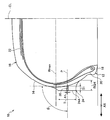
- FIG. 1 shows a sectional view in the tire radial direction of the pneumatic tire 10 according to the present embodiment (only one side across the tire equatorial plane CL).
- the pneumatic tire 10 according to the present embodiment includes a pair of bead parts 12, a pair of sidewall parts 14, and a tread part 16.
- the bead portion 12 has at least one annular bead core 18 embedded therein.
- a carcass 20 is provided between the pair of bead cores 18 so as to straddle a toroidal shape.
- the carcass 20 is wound around the bead core 18 from the inside to the outside.
- a belt layer 22 is provided on the outer side of the carcass 20 in the tire radial direction.
- the pair of sidewall portions 14 extend from the bead portion 12 outward in the tire radial direction.
- Each sidewall portion 14 is formed with a rim guard 24 (side rib) protruding from the outer surface.
- the rim guard 24 is continuously formed over the entire circumference of the tire.
- a flat outer surface 24A is formed on the outer side of the rim guard 24 in the tire axial direction AX.
- the flat outer surface 24A is a flat surface along the tire equatorial plane CL.
- the flat outer surface 24A is formed closer to the bead portion 12 than the maximum tire width position Wmax of the sidewall portion 14.
- the side wall portion 14 is in contact with the ground depending on traveling conditions. Even in this case, the grounding of the flat outer surface 24A can be avoided.
- damage to the pin hole 30 described later formed in the flat outer surface 24A can be avoided. Further, damage and dropout of a pin member 42 and a head 44 described later inserted into the pin hole 30 can be avoided.
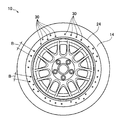
- pin holes 30 are formed in the flat outer surface 24 ⁇ / b> A of the rim guard 24.
- the pin hole 30 has a cylindrical shape extending along the tire axial direction AX.
- the extending direction of the pin hole 30 does not have to be along the tire axial direction AX, but the inclination angle ⁇ is within a range of 60 ° to 120 ° with respect to the tire equatorial plane CL (see FIG. 1). It is preferable.
- the inclination angle ⁇ within this range, the pin member can be prevented from falling off even if a centrifugal force is generated due to rotation when the tire is used at high speed.
- a plurality of pin holes 30 are formed along the tire circumferential direction of the rim guard 24.
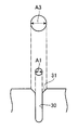
- the interval B between adjacent pin holes 30 is preferably 1.5 times or more the diameter A1 of the pin holes 30.
- the depth D1 of the pin hole 30 is preferably less than 85% of the thickness RGH in the tire axial direction AX of the sidewall portion 14 including the rim guard 24 at a position corresponding to the central axis P of the pin hole 30. In this way, by setting the depth D of the pin hole 30, the influence of the pin hole 30 on the tire frame member including the sidewall portion 14 can be suppressed.
- the diameter A1 (maximum diagonal length) of the pin hole 30 is preferably 50% or less of the tire radial direction length T of the flat outer surface 24A. In this way, by setting the diameter A1 of the pin hole 30, it is possible to suppress the crack propagation from the pin hole 30 to the sidewall portion 14.
- FIG. 4A and 4B show a mounting tool 40 to be mounted in the pin hole 30.
- the mounting tool 40 includes a pin member 42 and a head 44.
- the pin member 42 has a cylindrical shape.
- the diameter A2 of the pin member 42 is set larger than the diameter A1 of the pin hole 30.
- a head 44 is provided at one end of the pin member 42.
- the head 44 has a disk shape larger in diameter than the pin member 42, and the pin member 42 is disposed at the center of the disk.
- the outer surface of the head 44 is decorated.
- the pin member 42 and the head 44 may be separated and connected, or may be integrally formed.
- the pin member 42 is inserted into the pin hole 30 from the front end side (end portion where the head portion 44 is not provided), and the head portion 44 side is the rear end side of insertion.
- FIG. 5 shows a side surface of the tire in a state where the mounting tool 40 is mounted in the pin hole 30 illustrated in FIG. The head 44 is disposed outside the pin hole 30.
- the head member 44 When removing the mounting tool 40 from the pneumatic tire 10, the head member 44 may be pulled and the pin member 42 may be extracted from the pin hole 30.
- the mounting tool 40 can be inserted into and removed from the pin hole 30, so that the user can freely mount the favorite mounting tool 40. it can.
- the mounting tool 40 is not limited to a decoration, and a temperature sensor and a travel history measurement are not limited. It may be a measuring device such as, or other members.
- the shape of the head 44 does not need to be a disc shape, and may be a quadrangular plate shape, a triangular plate shape, or other free shapes.
- the pin hole 30 of the present embodiment has been described as an example in which the diameter of the opening portion and the intermediate portion is the same, but as shown in FIG.
- the part 31 may be formed.
- the pin member 42 can be easily inserted into the pin hole 30 by forming the tapered portion 31 in the opening.
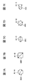
- the shape of the pin hole 30 viewed from the tire side is a circular shape, but the shape is not limited to this shape, and other shapes as shown in FIGS. 7A to 7E may be used. In addition, it can be a shape surrounded by continuous straight lines and curves.
- FIG. 7A shows a cross-shaped pin hole 30A.
- the maximum diagonal length is a position indicated by an arrow A1-A.
- FIG. 7B shows a rectangular (rectangular) pin hole 30B. A pair of diagonals of the pin hole 30B are chamfered, and a straight line connecting the other pair of diagonals has a maximum diagonal length A1-B.
- FIG. 7C shows an elliptical pin hole 30CB.
- the major axis of the ellipse is the maximum diagonal length A1-C of the pin hole 30C.
- FIG. 7D shows a star-shaped pin hole 30D.
- the straight line connecting the farthest ends of the star shape is the maximum diagonal length A1-D.
- FIG. 7E shows a keyhole-shaped pin hole 30E in which a circular shape and a trapezoid shape are connected. A straight line connecting one corner of the trapezoid and the circumference farthest from this is the maximum diagonal length A1-E.
- the present invention is not limited to this shape, and as illustrated in FIG. A conical pin hole 33A may be used. Moreover, it can be set as the shape enclosed by the continuous straight line and curve.
- a weight part with an extended pin hole may be formed at the bottom part.
- the weight portion 35B is formed at the bottom of the conical pin hole 33B
- the weight portion 35C is formed at the bottom of the cylindrical pin hole 33C.
- an engagement recess 37A having a concave wall surface may be formed in the intermediate portion in the depth direction of the pin hole 35A.
- the pin member 40A is formed with an engaging convex portion 46A that can be engaged with the engaging concave portion 37A. In this way, by engaging the engaging convex portion 46A with the engaging concave portion 37A, it is possible to prevent the wearing tool 40A from coming off.
- the engaging recess 37B may be formed in an annular shape formed over the entire circumference of the pin hole 35B.
- the pin member 40B is formed with an annular engagement convex portion 46A that can be engaged with the engagement concave portion 37B. In this manner, by engaging the engagement convex portion 46B with the engagement concave portion 37B, the attachment tool 40B can be prevented from coming off.
- Each shape of the pin hole can be a combination of a plurality of shapes.
- the shape viewed from the tire side can be a square shape and a quadrangular pyramid shape that narrows in the depth direction, and an engagement recess can be formed in the intermediate portion.
- the pin hole 30 is formed in the flat outer surface 24A of the rim guard 24 in this embodiment.
- the pin hole 30 may be formed in another part of the sidewall portion 14.
- the pin hole 30 may be formed in a convex portion, a rib or the like that is formed in the sidewall portion 14 and is different from the rim guard 24.
- the example in which the pin holes 30 are formed on both sides of the pair of sidewall portions 14 of the pneumatic tire 10 and the mounting tool 40 is mounted on the pin holes 30 has been described. There is no need, and it should be formed at least outside the vehicle.
- the tires of Examples 1 to 7 were assembled to a regular rim 6J15, a valve core was attached, and oxygen with a purity of 99% or more was filled to a filling pressure of 350 kPa, and then in a thermostatic chamber. It was left at 60 ° C. for 7 days for pre-oxygen degradation. Thereafter, the filling pressure in the tire was filled up to 230 KPa, and the vehicle was run up to a running distance of 20000 km at a test speed of 90 km / h at a load rate of 85% of the maximum load according to JATMA standards. After the test run, the presence or absence of circumferential cracks in adjacent pin holes and the presence or absence of cracks in the tire frame material were confirmed. Each result is as shown in Table 2.
- the tires of Examples 1 to 7 are assembled to the regular rim 6J15, and the tire load shape measurement tester is used to the wheel at the load factor (LI) 300% load factor. The presence or absence of pin hole contact was measured. Each result is as shown in Table 2.
Landscapes
- Engineering & Computer Science (AREA)
- Mechanical Engineering (AREA)
- Tires In General (AREA)
Abstract
装着具(40)を空気入りタイヤのサイドウォール部に装着する構造に関する。サイドウォール部には、ピン孔(30)が形成されている。ピン孔(30)に装着される装着具(40)は、ピン部材(42)及び頭部(44)を備えている。ピン部材(42)の直径(A2)は、ピン孔(30)の径(A1)よりも大径に設定されている。装着具(40)を空気入りタイヤに取り付ける場合には、ピン孔(30)にピン部材(42)を挿入する。
Description
本発明は、空気入りタイヤに関する。
従来から、タイヤのサイド部に装飾を施すため、リッジをデザイン配置したり、文字を配列したり、カラーリングしたりするなどの工夫がなされてきた(例えば、特開2008-273505号公報参照)。
しかしながら、上記した従来例では、装飾は予め施されており、ユーザーが自由に装飾を変更できるものではなかった。
本発明は、上記事実を考慮してなされたものであり、ユーザーが自由に装飾したり、その他の付属物を施したりすることが可能な空気入りタイヤを提供することを目的とする。
本発明の第1の態様の空気入りタイヤは、一対のタイヤサイドウォール部のうちの車両装着外側に配置される側に形成されたピン孔と、前記ピン孔の少なくとも一部の壁面を該ピン孔が拡張する方向に変形させつつ該ピン孔に挿入されると共に、該ピン孔から抜き出し可能とされたピン部材と、前記ピン部材の挿入後端側に設けられた頭部と、を有する装着具と、を備えている。
第1の態様に係る空気入りタイヤでは、ピン部材をピン孔に挿入することにより、ピン孔が拡張するように弾性変形する。これにより、ピン部材が、ピン孔の壁面の少なくとも一部における復元力によって保持されて、ピン部材の挿入後端側に設けられた頭部を含む装着具が装着される。また、ピン部材をピン孔から抜き出すことにより、装着具を取り外すことができる。これにより、ユーザーが好みの装着具を自由に装着することができる。
ここでの装着具は、装飾品、温度センサーなどの計測機器を含むものである。
本発明の第2の態様の空気入りタイヤは、前記タイヤサイドウォール部に突出したサイドリブを有し、前記ピン孔は、前記サイドリブに形成されていること、を特徴とする。
このように、サイドリブにピン孔を形成することにより、ピン孔の深さが確保しやすくなる。
本発明の第3の態様に係る空気入りタイヤは、前記サイドリブは平坦なフラット外面を有し、該フラット外面のタイヤ径方向最外端は、タイヤ最大幅位置よりもタイヤ径方向内側に配置されていること、を特徴とする。
上記の位置にサイドリブのフラット外面を形成することにより、走行条件によってタイヤサイドウォール部が接地する状況となっても、フラット外面の接地を回避することができる。したがって、このフラット外面に挿入されるピン部材、装着される頭部の損傷、脱落、フラット外面に形成されたピン孔部の損傷も回避することができる。
本発明の第4の態様に係る空気入りタイヤは、前記ピン孔の深さは、前記ピン孔が形成された部分における前記サイドリブを含むサイドウォール部のタイヤ軸方向の厚みの85%未満であること、を特徴とする。
このように、ピン孔の深さを設定することにより、ピン孔によるタイヤ骨格部材への干渉を抑制することができる。
本発明の第5の態様に係る空気入りタイヤは、前記ピン孔の最大対角長さは前記フラット外面のタイヤ径方向長さの50%以下であること、を特徴とする。
このように、ピン孔の最大対角長さを設定することにより、ピン孔からの亀裂進展を抑制することができる。
なお、空気入りタイヤの前記ピン孔は、タイヤサイド側からみて円形状、矩形状、多角形状、楕円形状、円形と矩形を結合させた鍵穴形状、とすることができる。
このように、ピン孔を種々の形状に形成することができる。
本発明の第6の態様に係る発明の空気入りタイヤは、前記ピン孔が、深さ方向に一定の断面を有する柱状部分を有していること、を特徴とする。
このように、柱状部分を有することにより、ピン孔を容易に形成することができる。
本発明の第7の態様に係る発明の空気入りタイヤは、前記ピン孔が、深さ方向に徐々に断面が小さくなる錐状部分を有していること、を特徴とする。
このように、錐状部分を有することにより、ピン部材の挿入及び抜き出しがし易くなる。
本発明の第8の態様に係る発明の空気入りタイヤは、前記ピン孔は、底部にピン孔が径方向に拡張された錘状部分を有していること、を特徴とする。
このように、錘状部分を有していることにより、ピン部材の抜け出しを抑制することができる。
本発明の第9の態様に係る発明の空気入りタイヤは、前記ピン孔には、深さ方向の中間部に壁面が凹となる係合凹部が形成され、前記ピン部材には、この係合凹部に対応する位置に、係合凸部が形成されていること、を特徴とする。
上記構成では、係合凹部に係合凸部が係合することにより、ピン部材の抜け出しを抑制することができる。
本発明の第10の態様に係る発明の空気入りタイヤは、前記ピン孔は、開口部が該開口部よりも奥側よりも大径とされていること、を特徴とする。
このように開口部を大径とすることにより、ピン孔へピン部材を挿入しやすくすることができる。
本発明の第11の態様に係る発明の空気入りタイヤは、隣り合う前記ピン孔の間隔は、前記ピン孔の最大対角長さの1.5倍以上であること、を特徴とする。
このようにピン孔の間隔を設定することにより、ピン孔を起点とするタイヤサイドウォール部の亀裂の進展を抑制することができる。
本発明の第12の態様に係る発明の空気入りタイヤは、前記ピン孔の深さ方向のタイヤ赤道面に対しての傾きは、60°~120°であること、を特徴とする。
この範囲内に、ピン孔の深さ方向のタイヤ赤道面に対しての傾きを設定することにより、タイヤ高速走行使用時における回転に伴う遠心力が作用しても、ピン部材の脱落を抑制することができる。
本発明に係る請求項1に記載の空気入りタイヤによれば、ピン部材の挿入、抜き出しにより、ユーザーが好みの装着具を自由に装着することができる。
請求項2に記載の空気入りタイヤによれば、サイドリブにピン孔が形成されているので、ピン孔の深さを容易に確保することができる。
請求項3に記載の空気入りタイヤによれば、フラット外面に挿入されるピン部材、装着される装着具の損傷、脱落、フラット外面に形成されたピン孔部の損傷を回避することができる。
請求項4に記載の空気入りタイヤによれば、ピン孔によるタイヤ骨格部材への干渉を抑制することができる。
請求項5に記載の空気入りタイヤによれば、ピン孔からの亀裂進展を抑制することができる。
なお、ピン孔は、種々の形状に形成することができる。
請求項6に記載の空気入りタイヤによれば、ピン孔を容易に形成することができる。
請求項7に記載の空気入りタイヤによれば、ピン部材の挿入及び抜き出しを容易に行うことができる。
請求項8に記載の空気入りタイヤによれば、ピン部材の抜け出しを抑制することができる。
請求項9に記載の空気入りタイヤによれば、ピン部材の抜け出しを抑制することができる。
請求項10に記載の空気入りタイヤによれば、ピン孔へピン部材を挿入しやすくすることができる。
請求項11に記載の空気入りタイヤによれば、ピン孔を起点とするタイヤサイドウォール部の亀裂の進展を抑制することができる。
請求項12に記載の空気入りタイヤによれば、ピン部材の脱落を抑制することができる。
以下、本発明を実施するための形態を図面に基づき説明する。本実施形態において規定する空気入りタイヤの各部の位置等は、JATMA YEAR BOOK(2011年度版、日本自動車タイヤ協会規格)に規定されている標準リムに装着し、JATMA YEAR BOOKでの適用サイズ・プライレーティングにおける最大負荷能力(内圧-負荷能力対応表の太字荷重)に対応する空気圧(最大空気圧)の100%の内圧を充填し、最大負荷能力を負荷したときのものである。なお、使用地又は製造地において、TRA規格、ETRTO規格が適用される場合は各々の規格に従う。
図1には、本実施形態に係る空気入りタイヤ10のタイヤ径方向断面図(タイヤ赤道面CLを挟んだ片側のみ)が示されている。本実施形態に係る空気入りタイヤ10は、一対のビード部12と、一対のサイドウォール部14と、トレッド部16とを有している。
ビード部12には、少なくとも1本の環状のビードコア18が埋設されている。一対のビードコア18間には、カーカス20がトロイダル状に跨るように設けられている。このカーカス20は、ビードコア18に対して内側から外側に巻き返されている。カーカス20のタイヤ径方向外側には、ベルト層22が設けられている。
一対のサイドウォール部14は、ビード部12からタイヤ径方向外側に夫々延設されている。各々のサイドウォール部14には、外表面から突出したリムガード24(サイドリブ)が形成されている。リムガード24は、タイヤ全周に亘って連続形成されている。リムガード24のタイヤ軸方向AXの外側には、フラット外面24Aが形成されている。フラット外面24Aは、タイヤ赤道面CLに沿った平坦面とされている。
空気入りタイヤ10のタイヤ最大幅位置をWmaxとすると、フラット外面24Aは、サイドウォール部14のタイヤ最大幅位置Wmaxよりもビード部12側に形成されている。なお、フラット外面24Aは、必ずしもタイヤ最大幅位置Wmaxよりもビード部12側に形成されている必要はないが、このように形成されていることにより、走行条件によってサイドウォール部14が接地する状況となっても、フラット外面24Aの接地を回避することができる。その結果、このフラット外面24Aに形成される後述のピン孔30の損傷も回避することができる。さらに、ピン孔30に挿入される後述のピン部材42、頭部44の損傷、脱落も回避することができる。
リムガード24のフラット外面24Aには、図2にも示すように、ピン孔30が形成されている。ピン孔30は、タイヤ軸方向AXに沿って延在する円柱形状とされている。なお、ピン孔30の延在方向は、タイヤ軸方向AXに沿っている必要はないが、タイヤ赤道面CLに対して60°~120°の範囲内の傾き角度θ(図1参照)とすることが好ましい。この範囲内に傾き角度θを設定することにより、タイヤ高速走行使用時における回転に伴う遠心力が作用しても、ピン部材の脱落を抑制することができる。
ピン孔30は、図3にも示すように、リムガード24のタイヤ周方向に沿って複数形成されている。隣り合うピン孔30同士の間隔Bは、ピン孔30の直径A1の1.5倍以上であることが好ましい。このように間隔Bを設定することにより、ピン孔30を起点とするサイドウォール部14の亀裂の進展を抑制することができる。
ピン孔30の深さD1は、ピン孔30の中心軸Pに対応する位置におけるリムガード24を含んだサイドウォール部14のタイヤ軸方向AXの厚みRGHの85%未満であることが好ましい。このように、ピン孔30の深さDを設定することにより、ピン孔30によるサイドウォール部14を含むタイヤ骨格部材への影響を抑制することができる。
また、ピン孔30の直径A1(最大対角長さ)は、フラット外面24Aのタイヤ径方向長さTの50%以下であることが好ましい。このように、ピン孔30の直径A1を設定することにより、ピン孔30からサイドウォール部14への亀裂進展を抑制することができる。
図4A及び図4Bには、ピン孔30に装着される装着具40が示されている。装着具40は、ピン部材42及び頭部44を備えている。ピン部材42は、円柱形状とされている。ピン部材42の直径A2は、ピン孔30の直径A1よりも大径に設定されている。
ピン部材42の一端部には頭部44が設けられている。頭部44はピン部材42よりも大径の円板状とされ、円板の中央部にピン部材42が配置されている。頭部44の外側面に装飾が施されている。なお、ピン部材42と頭部44とは、別体とされて連結されていてもよいし、一体的に形成されていてもよい。ピン部材42は、先端側(頭部44が設けられていない端部)からピン孔30に挿入され、頭部44側は挿入後端側となっている。
装着具40を空気入りタイヤ10に取り付ける場合には、ピン孔30にピン部材42を挿入する。このとき、ピン部材42の直径A2はピン孔30の直径A2よりも大径であるため、ピン孔30を形成する内壁は、ピン部材42に押されてピン孔30が拡張するように弾性変形する。したがって、ピン孔30に挿入されたピン部材42は、ピン孔30の内壁の復元力によって保持され、装着具40が装着される。図5には、図3に示されるピン孔30に装着具40が装着された状態のタイヤ側面が示されている。頭部44は、ピン孔30の外側に配置される。
装着具40を空気入りタイヤ10から取り外す場合には、頭部44を持って引っ張り、ピン部材42をピン孔30から抜き出せばよい。
本実施形態の空気入りタイヤ10によれば、装着具40をピン孔30へ挿入したり、ピン孔30から抜き出したりすることができるので、ユーザーが好みの装着具40を自由に装着することができる。
なお、本実施形態では、装着具40として、頭部44に装飾の施された装飾品を例に説明したが、装着具としては装飾品に限定されるものではなく、温度センサー、走行履歴計測などの計測機器や、その他の部材であってもよい。また、頭部44の形状は円板状である必要はなく、四角形板状、三角形板状、その他の自由な形状とすることができる。
また、本実施形態のピン孔30は、開口部と中間部の径が同じ形状のものを例に説明したが、図6に示すように、開口側が奥側よりも大径となるようなテーパー部31を形成してもよい。このように開口にテーパー部31を形成することにより、ピン孔30へピン部材42を容易に挿入することができる。
また、本実施形態では、ピン孔30のタイヤサイド側からみた形状を円形状としたが、この形状に限定されるものではなく、図7A~図7Eに示されるような他の形状としてもよく、その他に連続した直線と曲線で囲まれた形状とすることができる。
例えば、図7Aには、十字形状のピン孔30Aが示されている。この場合には、最大対角長さは、矢印A1-Aで示す位置となる。また、図7Bには、四角形状(矩形状)のピン孔30Bが示されている。ピン孔30Bの一対の対角は面取りされており、他の一対の対角を結ぶ直線が最大対角長さA1-Bとなる。
また、図7Cには、楕円形状のピン孔30CBが示されている。楕円の長径がピン孔30Cの最大対角長さA1-Cとなる。また、図7Dには、星形状のピン孔30Dが示されている。星型の最も離れた位置にある先端同士を結ぶ直線が最大対角長さA1-Dとなる。また、図7Eには、円形と台形を連結させた鍵穴形状のピン孔30Eが示されている。台形の一方の角部とここから最も離れた位置にある円周とを結ぶ直線が最大対角長さA1-Eとなる。
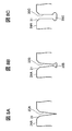
また、本実施形態では、ピン孔30が深さ方向に一定の断面を有する柱状である例について説明したが、この形状に限定されるものではなく、図8Aに示されるように、奥側が小径となるような円錐形状のピン孔33Aとしてもよい。また、その他に連続した直線と曲線で囲まれた形状とすることができる。
また、図8B、図8Cに示されるように、底部にピン孔を拡張した錘部を形成してもよい。図8Bでは、円錐形状のピン孔33Bの底部に錘部35Bを形成し、図8Cでは、円柱形状のピン孔33Cの底部に錘部35Cを形成している。
また、図9Aに示されるように、ピン孔35Aの深さ方向の中間部に壁面が凹となる係合凹部37Aが形成されていてもよい。この場合のピン部材40Aには、係合凹部37Aに係合可能な係合凸部46Aを形成する。このように、係合凹部37Aへ係合凸部46Aを係合させることにより、装着具40Aの抜けを抑制することができる。
また、図9Bに示されるように、係合凹部37Bを、ピン孔35Bの全周に亘って形成される環状としてもよい。この場合のピン部材40Bには、係合凹部37Bに係合可能な環状の係合凸部46Aを形成する。このように、係合凹部37Bへ係合凸部46Bを係合させることにより、装着具40Bの抜けを抑制することができる。
上記のピン孔についての各形状は、複数の形状を組み合わせることができる。例えば、タイヤサイド側からみた形状を四角形状にすると共に深さ方向に細くなる四角錐状とし、中間部に係合凹部を形成することができる。
なお、本実施形態では、リムガード24のフラット外面24Aにピン孔30を形成した例について説明したが、ピン孔30はサイドウォール部14の他の部分に形成されていてもよい。本実施形態のように、リムガード24に形成することにより、ピン孔30の深さを容易に確保することができる。
また、ピン孔30は、サイドウォール部14に形成された、リムガード24と異なる凸部、リブ等に形成してもよい。
また、本実施形態では、空気入りタイヤ10の一対のサイドウォール部14の両側にピン孔30が形成され、このピン孔30に装着具40が装着される例について説明したが、必ずしも両側である必要はなく、少なくとも車両装着外側に形成されていればよい。
[実施例]
タイヤサイズ 195/65R15 91V のタイヤについて、ピン孔及びリムガードのサイズを変えた実施例1~7を用いて、各種の試験を行った。ピン孔に装着される装着具は、すべての実施例において同一で図4に示す装着具であり、直径A2は3.3mm、ピン部材の長さD2は9.5mmとした。ピン孔及びリムガードのサイズについては、表1に示す通りである。

試験として、劣化亀裂進展耐久ドラム試験、高速耐久ドラム試験、及び、高負荷荷重時のホイールへのピン孔接触計測を行った。
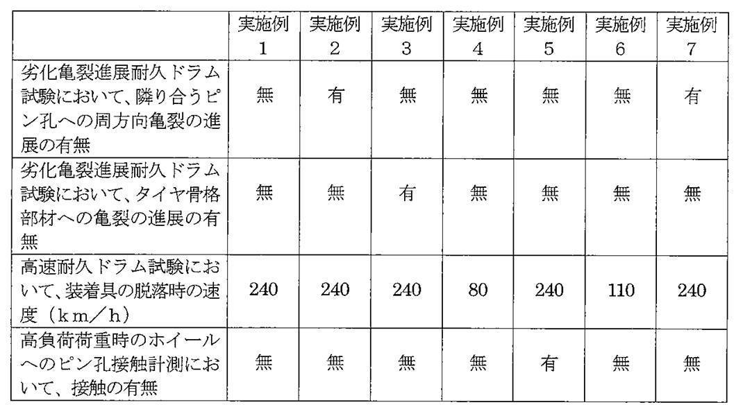
劣化亀裂進展耐久ドラム試験では、実施例1~7のタイヤを正規リム 6J15に組み付け、バルブコアを取り付けて、純度99%以上の酸素を充填圧が350kPaになるように充填し、その後恒温庫内に60℃で、7日間放置して事前酸素劣化させた。その後、タイヤ内の充填圧を230KPaまで充填し、JATMA準拠規格の最大荷重の85%の荷重負荷率にて試験速度90km/hで走行距離20000kmまで走行させた。試験走行後に、隣り合うピン孔への周方向亀裂の進展の有無、及び、タイヤ骨格材への亀裂到達の有無を確認した。各々の結果は、表2に示す通りである。
高速耐久ドラム試験では、実施例1~7のタイヤを正規リム 6J15に組み付け、正規内圧230kPaで内圧充填し、JATMA準拠規格の最大荷重の88%の荷重負荷率にて速度80km/hから最大速度240km/hまで30分毎に10km/hの速度を上昇させ、装着具がピン孔から抜け出てタイヤから脱落した時の速度を計測した。各々の結果は表2に示す通りである。
高負荷荷重時のホイールへのピン孔接触計測では、実施例1~7のタイヤを正規リム 6J15に組み付け、タイヤ負荷形状測定試験機にてLI(ロードインデックス)の300%負荷率時のホイールへのピン孔接触の有無を計測した。各々の結果は表2に示す通りである。
Claims (12)
- 一対のタイヤサイドウォール部のうちの車両装着外側に配置される側に形成されたピン孔と、
前記ピン孔の少なくとも一部の壁面を該ピン孔が拡張する方向に変形させつつ該ピン孔に挿入されると共に、該ピン孔から抜き出し可能とされたピン部材と、前記ピン部材の挿入後端側に設けられた頭部と、を有する装着具と、
を備えた空気入りタイヤ。 - 前記タイヤサイドウォール部に、突出したサイドリブを有し、
前記ピン孔は、前記サイドリブに形成されていること、を特徴とする請求項1に記載の空気入りタイヤ。 - 前記サイドリブは平坦なフラット外面を有し、該フラット外面のタイヤ径方向最外端は、タイヤ最大幅位置よりもタイヤ径方向内側に配置されていること、を特徴とする請求項2に記載の空気入りタイヤ。
- 前記ピン孔の深さは、前記ピン孔が形成された部分における前記サイドリブを含むサイドウォール部のタイヤ軸方向の厚みの85%未満であること、を特徴とする請求項2または請求項3に記載の空気入りタイヤ。
- 前記ピン孔の最大対角長さは前記フラット外面のタイヤ径方向長さの50%以下であること、を特徴とする請求項1~請求項4のいずれか1項に記載の空気入りタイヤ。
- 前記ピン孔は、深さ方向に一定の断面を有する柱状部分を有していること、を特徴とする請求項1~請求項5のいずれか1項に記載の空気入りタイヤ。
- 前記ピン孔は、深さ方向に徐々に断面が小さくなる錐状部分を有していること、を特徴とする請求項1~請求項6のいずれか1項に記載の空気入りタイヤ。
- 前記ピン孔は、底部にピン孔が径方向に拡張された錘状部分を有していること、他の部分よりも断面が大きくなる錘状部分を有していること、を特徴とする請求項1~請求項7のいずれか1項に記載の空気入りタイヤ。
- 前記ピン孔は、深さ方向の中間部に壁面が凹となる係合凹部が形成され、前記ピン部材には、この係合凹部に対応する位置に、係合凸部が形成されていること、を特徴とする請求項1~請求項8のいずれか1項に記載の空気入りタイヤ。
- 前記ピン孔は、開口部が該開口部よりも奥側よりも大径とされていること、を特徴とする請求項1~請求項9のいずれか1項に記載の空気入りタイヤ。
- 隣り合う前記ピン孔の間隔は、前記ピン孔の最大対角長さの1.5倍以上であること、を特徴とする請求項1~請求項10のいずれか1項に記載の空気入りタイヤ。
- 前記ピン孔の深さ方向のタイヤ赤道面に対しての傾きは、60°~120°であること、を特徴とする請求項1~請求項11のいずれか1項に記載の空気入りタイヤ。
Applications Claiming Priority (2)
| Application Number | Priority Date | Filing Date | Title |
|---|---|---|---|
| JP2011174233A JP2013035463A (ja) | 2011-08-09 | 2011-08-09 | 空気入りタイヤ |
| JP2011-174233 | 2011-08-09 |
Publications (1)
| Publication Number | Publication Date |
|---|---|
| WO2013021920A1 true WO2013021920A1 (ja) | 2013-02-14 |
Family
ID=47668428
Family Applications (1)
| Application Number | Title | Priority Date | Filing Date |
|---|---|---|---|
| PCT/JP2012/069747 Ceased WO2013021920A1 (ja) | 2011-08-09 | 2012-08-02 | 空気入りタイヤ |
Country Status (2)
| Country | Link |
|---|---|
| JP (1) | JP2013035463A (ja) |
| WO (1) | WO2013021920A1 (ja) |
Citations (3)
| Publication number | Priority date | Publication date | Assignee | Title |
|---|---|---|---|---|
| JP2005047320A (ja) * | 2003-07-30 | 2005-02-24 | Toyo Tire & Rubber Co Ltd | 空気入りタイヤ |
| WO2005082644A1 (ja) * | 2004-03-02 | 2005-09-09 | Bridgestone Corporation | 空気入りタイヤ用電子デバイス固定システム、空気入りタイヤ及び電子デバイス収容装置 |
| JP2008049842A (ja) * | 2006-08-24 | 2008-03-06 | Toyota Motor Corp | バランスウエイト取付構造 |
-
2011
- 2011-08-09 JP JP2011174233A patent/JP2013035463A/ja not_active Withdrawn
-
2012
- 2012-08-02 WO PCT/JP2012/069747 patent/WO2013021920A1/ja not_active Ceased
Patent Citations (3)
| Publication number | Priority date | Publication date | Assignee | Title |
|---|---|---|---|---|
| JP2005047320A (ja) * | 2003-07-30 | 2005-02-24 | Toyo Tire & Rubber Co Ltd | 空気入りタイヤ |
| WO2005082644A1 (ja) * | 2004-03-02 | 2005-09-09 | Bridgestone Corporation | 空気入りタイヤ用電子デバイス固定システム、空気入りタイヤ及び電子デバイス収容装置 |
| JP2008049842A (ja) * | 2006-08-24 | 2008-03-06 | Toyota Motor Corp | バランスウエイト取付構造 |
Also Published As
| Publication number | Publication date |
|---|---|
| JP2013035463A (ja) | 2013-02-21 |
Similar Documents
| Publication | Publication Date | Title |
|---|---|---|
| JP5983731B2 (ja) | スタッドピン及び空気入りタイヤ | |
| JP5831646B2 (ja) | スタッドピン及び空気入りタイヤ | |
| EP3208115B1 (en) | Pneumatic tire | |
| JP4947225B1 (ja) | 空気入りタイヤ | |
| JP5849600B2 (ja) | 空気入りタイヤ | |
| CA3065233C (en) | Winter tire stud | |
| JP2019513626A (ja) | 補強コードアンテナを有する電子デバイスを備えたタイヤ | |
| JP2013224134A (ja) | 空気入りタイヤ | |
| WO2016098394A1 (ja) | 空気入りタイヤ | |
| JP2012131351A (ja) | 空気入りタイヤおよびスタッドピン | |
| CN107336569B (zh) | 防滑钉、充气轮胎及其制造方法以及防滑钉安装方法 | |
| CN108349330A (zh) | 防滑钉以及镶钉轮胎 | |
| WO2015107864A1 (ja) | スタッドピン及び空気入りタイヤ | |
| JPWO2018158800A1 (ja) | スタッドピン、およびスタッドタイヤ | |
| CN108025602B (zh) | 充气轮胎以及防滑钉 | |
| CN104093575A (zh) | 充气轮胎 | |
| JP2013035463A (ja) | 空気入りタイヤ | |
| JP2016107798A (ja) | 空気入りタイヤ | |
| EP4046825B1 (en) | Pneumatic tire | |
| EP3722110A1 (en) | Tire tread with stud arrangement | |
| JP2013230801A (ja) | タイヤ | |
| WO2015080251A1 (ja) | 空気入りタイヤ | |
| JP2013039844A (ja) | 空気入りタイヤ | |
| JP2008049842A (ja) | バランスウエイト取付構造 | |
| JP7243213B2 (ja) | スタッドピン、及びスタッドタイヤ |
Legal Events
| Date | Code | Title | Description |
|---|---|---|---|
| 121 | Ep: the epo has been informed by wipo that ep was designated in this application |
Ref document number: 12822901 Country of ref document: EP Kind code of ref document: A1 |
|
| NENP | Non-entry into the national phase |
Ref country code: DE |
|
| 122 | Ep: pct application non-entry in european phase |
Ref document number: 12822901 Country of ref document: EP Kind code of ref document: A1 |