WO2013019069A2 - 삼킴 장애 측정 및 치료 장치 - Google Patents
삼킴 장애 측정 및 치료 장치 Download PDFInfo
- Publication number
- WO2013019069A2 WO2013019069A2 PCT/KR2012/006132 KR2012006132W WO2013019069A2 WO 2013019069 A2 WO2013019069 A2 WO 2013019069A2 KR 2012006132 W KR2012006132 W KR 2012006132W WO 2013019069 A2 WO2013019069 A2 WO 2013019069A2
- Authority
- WO
- WIPO (PCT)
- Prior art keywords
- ultrasonic
- swallowing disorder
- swallowing
- measuring
- receiver
- Prior art date
Links
Images


Classifications
-
- A—HUMAN NECESSITIES
- A61—MEDICAL OR VETERINARY SCIENCE; HYGIENE
- A61N—ELECTROTHERAPY; MAGNETOTHERAPY; RADIATION THERAPY; ULTRASOUND THERAPY
- A61N1/00—Electrotherapy; Circuits therefor
- A61N1/18—Applying electric currents by contact electrodes
- A61N1/32—Applying electric currents by contact electrodes alternating or intermittent currents
- A61N1/36—Applying electric currents by contact electrodes alternating or intermittent currents for stimulation
- A61N1/36007—Applying electric currents by contact electrodes alternating or intermittent currents for stimulation of urogenital or gastrointestinal organs, e.g. for incontinence control
-
- A—HUMAN NECESSITIES
- A61—MEDICAL OR VETERINARY SCIENCE; HYGIENE
- A61B—DIAGNOSIS; SURGERY; IDENTIFICATION
- A61B8/00—Diagnosis using ultrasonic, sonic or infrasonic waves
- A61B8/08—Detecting organic movements or changes, e.g. tumours, cysts, swellings
-
- A—HUMAN NECESSITIES
- A61—MEDICAL OR VETERINARY SCIENCE; HYGIENE
- A61B—DIAGNOSIS; SURGERY; IDENTIFICATION
- A61B5/00—Measuring for diagnostic purposes; Identification of persons
- A61B5/42—Detecting, measuring or recording for evaluating the gastrointestinal, the endocrine or the exocrine systems
- A61B5/4205—Evaluating swallowing
-
- A—HUMAN NECESSITIES
- A61—MEDICAL OR VETERINARY SCIENCE; HYGIENE
- A61N—ELECTROTHERAPY; MAGNETOTHERAPY; RADIATION THERAPY; ULTRASOUND THERAPY
- A61N1/00—Electrotherapy; Circuits therefor
- A61N1/02—Details
- A61N1/04—Electrodes
- A61N1/0404—Electrodes for external use
- A61N1/0408—Use-related aspects
- A61N1/0452—Specially adapted for transcutaneous muscle stimulation [TMS]
-
- A—HUMAN NECESSITIES
- A61—MEDICAL OR VETERINARY SCIENCE; HYGIENE
- A61N—ELECTROTHERAPY; MAGNETOTHERAPY; RADIATION THERAPY; ULTRASOUND THERAPY
- A61N1/00—Electrotherapy; Circuits therefor
- A61N1/18—Applying electric currents by contact electrodes
- A61N1/32—Applying electric currents by contact electrodes alternating or intermittent currents
- A61N1/36—Applying electric currents by contact electrodes alternating or intermittent currents for stimulation
- A61N1/3601—Applying electric currents by contact electrodes alternating or intermittent currents for stimulation of respiratory organs
-
- A—HUMAN NECESSITIES
- A61—MEDICAL OR VETERINARY SCIENCE; HYGIENE
- A61N—ELECTROTHERAPY; MAGNETOTHERAPY; RADIATION THERAPY; ULTRASOUND THERAPY
- A61N1/00—Electrotherapy; Circuits therefor
- A61N1/18—Applying electric currents by contact electrodes
- A61N1/32—Applying electric currents by contact electrodes alternating or intermittent currents
- A61N1/36—Applying electric currents by contact electrodes alternating or intermittent currents for stimulation
- A61N1/36014—External stimulators, e.g. with patch electrodes
- A61N1/3603—Control systems
- A61N1/36031—Control systems using physiological parameters for adjustment
Definitions
- the present invention relates to a swallowing disorder measurement and treatment device, and more particularly to a portable swallowing disorder measurement and treatment device.
- Swallowing Disorder is a generic term used to describe the difficulties that occur during the process of eating.It occurs in patients with stroke, degenerative diseases of the central and peripheral nerves, traumatic brain diseases, head and neck tumors, and muscle diseases. do.
- Swallowing disorders occur in as few as 29% and as many as 64% in stroke patients, and up to 81% in Parkinson patients.
- swallowing disorders may occur due to external influences such as general cognition and physical condition of the patient or external influences such as airway intubation or tracheostomy.
- the degree of disease and the degree is different, but if swallowing disorders, such as aspiration, pneumonia, dehydration, malnutrition, and the like, may cause death due to these problems.
- Swallowing disorders include oral stages in which food is put in the mouth, chewed, mixed with saliva to form agglomerates and pushed into the pharynx, food entering the pharyngeal cavity, palpation, hyoidary cartilage
- the pharyngeal cavity phase leads to the esophageal entry through a series of precisely coordinated movements of various pharyngeal cavity internal structures, including pharyngeal peristalsis and upper esophageal sphincter relaxation. It consists of an inflow stage where food is introduced into the esophagus through the relaxation of the bare muscles.
- the oral phase is a step that can be observed with the naked eye, so it can be evaluated relatively accurately without special equipment.However, in the pharyngeal cavity phase, there is only the movement of the neck that looks and feels fine during the swallowing operation. can confirm.
- Conventional swallowing disorder measuring apparatuses include the VideoFluoroscopic Swallowing Study (VFSS) and the Fiberoptic Endoscopic Evaluation of Swallowing (FEES).
- VFSS VideoFluoroscopic Swallowing Study
- FEES Fiberoptic Endoscopic Evaluation of Swallowing
- the video fluoroscopy device records images projected on a fluorescent screen using x-rays, and can visually identify the anatomical structures involved in swallowing, and perform functional abnormalities while swallowing. It is used to evaluate whether or not.
- the video endoscopy device inserts a flexible endoscope through the nose to observe the structure of the pharyngeal cavity before and after swallowing, and the oral cavity and pharyngeal cavity function when swallowing cannot be confirmed. have.
- Such conventional swallowing disorder measuring apparatus has some limitations in clinical use.
- the conventional swallowing disorder measuring apparatus is large and considerably expensive, and its main purpose is not to measure swallowing disorder only, and it is difficult to construct and use the apparatus without the cooperation of radiology and otolaryngology.
- small-scale hospitals and institutions that deal with swallowing disorders fail to properly test for swallowing disorders, and many patients with swallowing disorders are often overlooked or only treating swallowing disorders without accurate evaluation.
- the video fluoroscopy device has radiation exposure, and the video endoscopic device is an invasive method of inserting the endoscope through the nose, which is relatively short time. It is difficult to identify the characteristics of swallowing disorders in the daily life of each patient because swallowing tests must be performed in-house.
- the conventional method of treating swallowing disorder is to give electric stimulation to patients with swallowing disorders showing lower hyoid laryngopharyngeal movement and esophageal laxity.
- Transcutaneous Electrical Stimulation (TES) and neuromuscular muscles There is a Neuromuscular Electrical Stimulation (NES).
- Percutaneous electrical stimulation is a rehabilitation exercise exercise that attempts to stimulate the nerves and muscles under the skin by performing electrical stimulation on the damaged area while performing a functional task. Such percutaneous electrical stimulation is to treat the future of swallowing by inducing electrical stimulation to the surface of the neck and inducing swallowing.
- percutaneous electrical stimulation can be used to treat atrophic or nerve damaged muscles, there is a limitation that does not cause actual contraction of such muscles.
- Neuromuscular electrical stimulation is a method of increasing the strength of muscles by repeatedly acting electrical stimulation to the muscles and even the muscles of the neurologically damaged muscles and the remaining muscle function of electrical stimulation acts repeatedly.
- This neuromuscular electrical stimulation method is applied to the treatment of swallowing disorders, by repeating the swallowing operation by attaching an electrode to the external muscles of the neck that acts on swallowing and improves muscle movement when swallowing.
- Chattanooga VitalSTim is a device designed to treat swallowing disorders by considering which muscles are stimulated and which patterns should be stimulated in the external muscles of the neck involved with swallowing.
- the present invention is to solve the problems of the above-described background, to provide a device for measuring and treating a swallowing disorder, which can measure the swallowing disorder and at the same time treat the swallowing disorder.
- Swallowing disorder measurement and treatment device is at least one sensor unit for measuring the swallowing disorder attached to the neck of the patient, swallowing disorder measured in the sensor unit for measuring the swallowing disorder attached to the neck of the patient
- At least one electrical stimulation electrode unit for solving the swallowing disorder by giving an electrical stimulation to the neck of the patient according to the signal may include a control unit for controlling the swallowing disorder measuring sensor unit and the electrical stimulation electrode unit.
- the display analyzer may further include a display analyzer connected to the controller and configured to display and analyze the swallowing disability signal.
- the swallowing disorder measuring sensor unit may include an ultrasonic transmitter and an ultrasonic receiver.
- the ultrasonic receiver may be spaced apart from the ultrasonic transmitter.
- the ultrasonic receiver surrounds the ultrasonic transmitter.
- the ultrasonic transmitter and the ultrasonic receiver may be disposed in a donut shape as a whole.
- the ultrasonic transmitter and the ultrasonic receiver may be arranged in a rectangular shape as a whole.
- the ultrasonic transmitter and the ultrasonic receiver may be arranged in a polygonal shape as a whole.
- the apparatus may further include an ultrasonic sound absorber disposed between the ultrasonic transmitter and the ultrasonic receiver.
- the ultrasonic transmitter may further include an ultrasonic lens attached to a front surface of the ultrasonic transmitter and the ultrasonic receiver and covering the ultrasonic transmitter and the ultrasonic receiver.
- the apparatus may further include a voice conversion device connected to the control unit and converting the swallowing disturbance signal into voice.
- the storage device may further include a storage device connected to the control unit and storing the swallowing failure signal in real time.
- the electrical stimulation electrode unit may be pre-programmed to give electrical stimulation in real time when swallowing disorders.
- the ultrasonic receiver may include a main ultrasonic receiver and a preliminary ultrasonic receiver adjacent to the main ultrasonic receiver.
- the apparatus may further include a sensor body in which the ultrasonic transmitter and the ultrasonic receiver are located.
- the ultrasonic transmitter and the ultrasonic receiver may be inserted into a sensor groove formed in the sensor body.
- the surface of the sensor body may be curved.
- Surfaces of the ultrasonic transmitter and the ultrasonic receiver may be connected to each other to form a curved surface.
- the back of the sensor main body may be formed with a belt groove to which the fixing belt is fixed.
- Swallowing disorder measurement and treatment device by simply providing an electrical stimulation electrode portion to solve the swallowing disorder by giving electrical stimulation to the neck of the patient according to the swallowing disorder signal measured by the sensor for measuring the swallowing disorder,
- the swallowing disorder can be treated and the swallowing disorder can be treated using the electrical stimulation electrode.
- the swallowing disorder measurement and treatment device can measure the swallowing disorder in a simple, non-invasive way without using a complicated swallowing disorder measuring device such as a video fluoroscopy device or a video endoscopy device. Can be.
- the swallowing disorder measurement and treatment device by installing a display analysis unit for displaying and analyzing the swallowing disorder signal, it is possible to simultaneously monitor the patient's response while treating the swallowing disorder whether the patient responds properly At the same time as evaluating, the patient himself can see the response he / she has performed and can act as a feedback.
- a separate preliminary ultrasonic receiver may be disposed to increase the ultrasonic reception sensitivity when the ultrasonic reception sensitivity is weak.
- the surface of the sensor main body be a curved surface, the adhesion of the human body can be improved, and the durability of the sensor unit for measuring swallowing disorder can be improved.
- 1 is an overall configuration of the swallowing disorder measurement and treatment apparatus according to a first embodiment of the present invention.
- FIG. 2 is a control flowchart of the controller of the swallowing disorder measurement and treatment apparatus according to the first embodiment of the present invention.
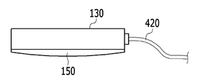
- FIG 3 is a side view of a sensor for measuring swallowing disorder of the apparatus for measuring and treating swallowing disorder according to a first embodiment of the present invention.
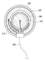
- FIG. 4 is a plan view of a swallowing disorder measuring sensor unit of the swallowing disorder measuring and treating apparatus according to the first embodiment of the present invention.
- FIG 5 is an enlarged view of the electrical stimulation electrode unit of the swallowing disorder measurement and treatment apparatus according to the first embodiment of the present invention.
- Figure 6 is an exemplary use of the swallowing disorder measurement and treatment device according to a first embodiment of the present invention applied to patients with swallowing disorder.
- FIG. 7 is a diagram illustrating a swallowing disability signal displayed on an analysis display of the swallowing disorder measuring and treating apparatus according to the first embodiment of the present invention.
- FIG. 8 is a plan view of a swallowing disorder measuring sensor unit of the swallowing disorder measuring and treating apparatus according to the second embodiment of the present invention.
- FIG. 9 is a plan view of a swallowing disorder measuring sensor unit of a swallowing disorder measuring and treating apparatus according to a third embodiment of the present invention.
- FIG. 10 is a cross-sectional view of a sensor for measuring swallowing disorder of the apparatus for measuring and treating swallowing disorder according to a third embodiment of the present invention.
- FIG. 11 is a plan view of a swallowing disorder measuring sensor unit of a swallowing disorder measuring and treating apparatus according to a fourth embodiment of the present invention.
- FIG. 12 is a plan view of a swallowing disorder measuring sensor unit of a swallowing disorder measuring and treating apparatus according to a fifth embodiment of the present invention.
- FIG. 13 is a perspective view of a sensor for measuring swallowing disorder of the apparatus for measuring and treating swallowing disorder according to a fifth embodiment of the present invention.
- ultrasonic sound absorbing unit 150 ultrasonic lens
- FIG. 1 is an overall configuration diagram of a swallowing disorder measurement and treatment apparatus according to a first embodiment of the present invention
- Figure 2 is a control flowchart of a control unit of the swallowing disorder measurement and treatment apparatus according to a first embodiment of the present invention
- 3 is a side view of the swallowing disorder measuring device and treatment device according to the first embodiment of the present invention
- the swallowing sensor measurement unit Figure 4 is a swallowing disorder measuring device and treatment device according to the first embodiment of the present invention
- 5 is a plan view of the measuring sensor unit
- FIG. 5 is an enlarged view of the electrical stimulation electrode unit of the swallowing disorder measuring and treating apparatus according to the first embodiment of the present invention.
- the swallowing disorder measuring and treating apparatus includes at least one sensory measuring unit 100 for measuring the swallowing disorder attached to the neck of the patient 1, the patient At least one electrical stimulation electrode unit 200 that is attached to the neck of the patient to solve the swallowing disorder by giving electrical stimulation to the neck of the patient according to the swallowing disorder signal measured by the sensor unit 100 for measuring swallowing disorder, It includes a control unit 300 for controlling the sensor unit 100 and the electrical stimulation electrode unit 200 and the main body 400 in which the control unit 300 is located.
- the sensor unit 100 for measuring swallowing disorder is connected through a sensor plug 410 and a sensor cable 420 of the main body 400.
- the sensor unit 100 for measuring swallowing disorder transmits an ultrasonic wave and measures a modulation cycle of ultrasonic waves reflected and modulated by food or acupuncture moving to the patient's esophagus, and confirms the movement of food or acupuncture into the esophagus.
- the sensor unit 100 for measuring swallowing disorder is a type of ultrasonic sensor for measuring a series of movements inside the pharyngeal cavity of the neck.
- the sensor unit 100 for swallowing disorder measurement includes an ultrasonic transmitter 110 for transmitting ultrasonic waves and an ultrasonic receiver 120 for detecting the reflected ultrasonic waves, and an ultrasonic transmitter ( 110 and the sensor body 130 in which the ultrasonic receiver 120 is located.
- the ultrasonic transmitter 110 and the ultrasonic receiver 120 may be located in one sensor main body 130 as in an embodiment of the present invention, but the ultrasonic transmitter 110 and the ultrasonic receiver 120 are separate from each other. It may be located in the sensor body 130.
- the ultrasonic transmitter 110 may have a shape such as a circle, a square, a polygon, and the like, and the ultrasonic receiver 120 may be spaced apart from the ultrasonic transmitter 110.
- the ultrasonic receiver 120 surrounds the ultrasonic transmitter 110.
- a connection line 115 connecting the ultrasonic transmitter 110 and the ultrasonic receiver 120 is installed to transmit and receive ultrasonic signals between the ultrasonic transmitter 110 and the ultrasonic receiver 120.
- the ring-shaped ultrasonic sound absorbing unit 140 is positioned between the ultrasonic transmitting unit 110 and the ultrasonic receiving unit 120.
- the ultrasonic sound absorbing unit 140 blocks the ultrasonic waves generated from the ultrasonic transmitting unit 110 from being directly transmitted to the ultrasonic receiving unit 120.
- the ultrasonic sound absorbing unit 140 is formed between the ultrasonic transmitting unit 110 and the ultrasonic receiving unit 120 in the form of a molding using a sound absorbing material.
- the ultrasonic sound absorbing unit 140 may include a noise shielding material for blocking noise.
- An ultrasonic lens 150 covering the ultrasonic transmitter 110 and the ultrasonic receiver 120 is attached to the ultrasonic transmitter 110 and the ultrasonic receiver 120.
- the ultrasonic lens 150 improves the adhesion to the skin when it comes in contact with the patient's neck, protects the inside of the sensor from shocks that may be applied to the sensor surface, and adjusts the radial shape of the ultrasonic wave by changing the physical structure so that the ultrasonic wave is fixed. Focusing on the point increases the concentration of the ultrasound.
- the electrical stimulation electrode unit 200 is connected to the electrical stimulation plug 430 and the electrical stimulation cable 440 of the main body 400.
- the electrical stimulation electrode unit 200 is attached to the sensor unit 100 for measuring swallowing disorder and the patient's neck through electrical stimulating electrodes 201 and 202 at the same time to give electrical stimulation to the patient's neck according to the swallowing disability signal. Relaxation and contraction of the esophageal sphincter allows food to enter the esophagus.
- the controller 300 includes a microcontroller A, an ultrasonic sensor controller B, an electrical stimulation controller C, a data collection device unit D, an ultrasonic voice converter E, and an interface unit F.
- the microcontroller A controls the ultrasonic sensor controller B, the electrical stimulation controller C, the ultrasonic voice conversion unit E, the data collection device unit D, and the interface unit F in the control unit 300.
- the microcontroller A controls the ultrasonic sensor controller B to generate ultrasonic waves of a specific frequency in the sensor unit 100 for measuring swallowing disorder by a predetermined control algorithm.
- the ultrasonic sensor controller B generates the continuous or pulsed ultrasonic wave in the sensor unit 100 for swallowing disorder measurement according to the use environment, and the frequency of the generated ultrasonic wave has an oscillation period of 2 MHz to 10 MHz.
- the microcontroller A determines a pattern of a predetermined electrical stimulus, a current intensity, an electrical
- the electrical stimulation controller C is controlled to transmit the period of the stimulus to the electrical stimulation electrode unit 200.
- the electrical stimulation controller C controls the electrical stimulation electrode unit 200 to electrically stimulate the upper sphincter of the esophagus so that food is introduced into the esophagus and food or saliva does not enter the airways.
- the microcontroller A collects the swallowing failure signal measured by the swallowing failure measuring sensor unit 100 to the data collecting device unit D, and the swallowing failure signal collected in the data collecting device unit D is stored in the storage device 500. B is transmitted to the display analyzer 600 in real time through the interface unit (F).
- the display analyzer 600 is connected to the controller 300, and the display analyzer 600 displays and analyzes the swallowing disability signal.
- the storage device 500 may be connected to the main body 400 to store the swallowing disorder signal measured by the sensor unit 100 for measuring the swallowing disorder.
- the swallowing failure signal stored in the storage device 500 may be transmitted to the display analyzer 600 in real time.
- the main body 400 has a built-in USB communication port 310 connected to the interface unit (F), the swallowing failure signal measured from the sensor unit 100 for measuring swallowing disorder using the USB communication port 310. May be transmitted to the display analyzer 600 in real time for analysis.
- the voice conversion device 700 such as a speaker or earphone
- the main body 400 to convert the swallowing disturbance signal measured by the sensor unit 100 for measuring the swallowing disorder to the voice frequency in the ultrasonic voice conversion unit (E).
- E ultrasonic voice conversion unit
- Figure 6 is an exemplary use of the swallowing disorder measurement and treatment device according to a first embodiment of the present invention applied to patients with swallowing disorder.
- the sensor unit 100 for measuring swallowing disorder is attached to an optimal position in which the swallowing disorder can be measured in the neck of the patient 1, and the electrical part is placed at a position capable of stimulating the upper sphincter of the esophagus.
- the magnetic pole electrode part 200 is attached.
- the swallowing disorder measurement signal is measured using the swallowing disorder measuring sensor unit 100, the swallowing disorder is evaluated in real time using the display analyzer 600, and the electrical stimulation electrode unit 200 is based on the evaluated result.
- two swallowing disorder measuring sensor units 100 may be attached to both sides of the front portion of the neck to more efficiently measure the swallowing disorder of the patient. In this case, the remaining diagnostic methods are the same.
- the swallowing disorder measuring and treating apparatus provides an electrical stimulation to the neck of the patient according to the swallowing disorder measuring sensor unit 100 for measuring the swallowing disorder signal and the swallowing disorder signal.
- the electrical stimulation electrode unit 200 By installing the electrical stimulation electrode unit 200 to solve, the swallowing disorder can be measured easily and the swallowing disorder can be treated using the electrical stimulation electrode unit 200.
- the swallowing disorder measurement and treatment device by installing the display analysis unit 600 for displaying and analyzing the swallowing disorder signal, the hyoid cartilage of the cartilage during the series of movement of the pharyngeal cavity associated with swallowing
- the display analysis unit 600 for displaying and analyzing the swallowing disorder signal
- the hyoid cartilage of the cartilage during the series of movement of the pharyngeal cavity associated with swallowing
- FIG. 7 is a diagram illustrating a swallowing disability signal displayed on an analysis display of the swallowing disorder measuring and treating apparatus according to the first embodiment of the present invention.
- FIG. 7 shows swallowing disorder signals 51, 52, 53, and 54 when swallowing water, bananas, yogurts, and biscuits, and it can be seen that various forms of swallowing disorder signals appear according to each food.
- the ultrasonic transmitter 110 has a shape of a circle, a square, a polygon, or the like, and the ultrasonic receiver 120 is spaced apart from the ultrasonic transmitter 110 to surround the ultrasonic transmitter 110.
- the ultrasonic transmitter 110 and the ultrasonic receiver 120 may each have a half donut shape corresponding to half of a donut shape, and may be disposed to face each other to form one donut shape as a whole.
- FIG. 8 is a plan view of a swallowing disorder measuring sensor unit of the swallowing disorder measuring and treating apparatus according to the second embodiment of the present invention.
- the second embodiment is substantially the same as the first embodiment shown in FIG. 4 except for the structure of the ultrasonic transmitter and the ultrasonic receiver, and thus repeated description thereof will be omitted.
- the sensor unit 100 for measuring swallowing disorder of the swallowing disorder measuring and treating apparatus is reflected by the ultrasonic transmitter 110 for transmitting ultrasonic waves and the ultrasonic waves reflected back.
- Ultrasonic receiving unit 120 for detecting the ultrasonic transmitter 110 and the ultrasonic receiver 120 includes a sensor body 130 is located.
- the ultrasonic transmitter 110 and the ultrasonic receiver 120 may be located in one sensor main body 130 as in an embodiment of the present invention, but the ultrasonic transmitter 110 and the ultrasonic receiver 120 are separate from each other. It may be located in the sensor body 130.
- the ultrasonic transmitter 110 is a half donut shape corresponding to half of a donut shape, and the ultrasonic receiver 120 facing the ultrasonic transmitter 110 is also a half donut shape.
- the ultrasonic transmitter 110 and the ultrasonic receiver 120 are spaced apart from each other, and are disposed in a donut shape as a whole.
- a connection line 115 connecting the ultrasonic transmitter 110 and the ultrasonic receiver 120 is installed to transmit and receive ultrasonic signals between the ultrasonic transmitter 110 and the ultrasonic receiver 120.
- the plate-shaped ultrasonic sound absorbing unit 140 is positioned between the ultrasonic transmitting unit 110 and the ultrasonic receiving unit 120.
- the ultrasonic sound absorbing unit 140 blocks the ultrasonic waves generated from the ultrasonic transmitting unit 110 from being directly transmitted to the ultrasonic receiving unit 120.
- the ultrasonic transmitter 110 and the ultrasonic receiver 120 may be disposed in a plane or arranged to have a predetermined angle with respect to the ultrasonic sound absorber 140 to increase the concentration of ultrasonic waves by focusing the ultrasonic waves to a predetermined point. .
- the ultrasonic transmitter and the ultrasonic receiver are disposed in a donut shape as a whole, but the ultrasonic transmitter and the ultrasonic receiver may be arranged in a rectangular or polygonal shape facing each other.
- FIG. 9 is a plan view of the sensor unit for measuring the swallowing disorder measurement and treatment of swallowing disorders according to a third embodiment of the present invention
- Figure 10 is a measurement of swallowing disorders of the swallowing disorder measurement and treatment apparatus according to a third embodiment of the present invention It is sectional drawing of the sensor part.
- the third embodiment is substantially the same as the second embodiment shown in FIG. 8 except for the structure of the sensor unit for swallowing disorder measurement, repeated description is omitted.
- the sensor unit 100 for measuring swallowing disorder of the swallowing disorder measuring and treating apparatus is reflected by the ultrasonic transmitter 110 transmitting ultrasonic waves. It includes an ultrasonic receiver 120, the ultrasonic transmitter 110 and the sensor body 130, the ultrasonic receiver 120 for detecting the returned ultrasonic waves.
- the ultrasonic transmitter 110 and the ultrasonic receiver 120 may be located in one sensor main body 130 as in an embodiment of the present invention, but the ultrasonic transmitter 110 and the ultrasonic receiver 120 are separate from each other. It may be located in the sensor body 130.
- the ultrasonic transmitter 110 has a square shape, and the ultrasonic receiver 120 facing the ultrasonic transmitter 110 is also square, and the ultrasonic transmitter 110 and the ultrasonic receiver 120 are spaced apart from each other.
- the ultrasonic transmitter 110 and the ultrasonic receiver 120 may be gathered together and disposed in a rectangular shape as a whole, or may be arranged in a polygonal shape as a whole.
- a connection line 115 connecting the ultrasonic transmitter 110 and the ultrasonic receiver 120 is installed to transmit and receive ultrasonic signals between the ultrasonic transmitter 110 and the ultrasonic receiver 120.
- the plate-shaped ultrasonic sound absorbing unit 140 is positioned between the ultrasonic transmitting unit 110 and the ultrasonic receiving unit 120.
- the ultrasonic sound absorbing unit 140 blocks the ultrasonic or electrical noise generated by the ultrasonic transmitting unit 110 from being directly transmitted to the ultrasonic receiving unit 120.
- the ultrasonic transmitter 110 and the ultrasonic receiver 120 may be disposed in a plane or arranged to have a predetermined angle with respect to the ultrasonic sound absorber 140 to increase the concentration of ultrasonic waves by focusing the ultrasonic waves to a predetermined point. .
- An ultrasonic lens 150 covering the ultrasonic transmitter 110 and the ultrasonic receiver 120 is attached to the ultrasonic transmitter 110 and the ultrasonic receiver 120.
- the ultrasound lens 150 is in contact with the neck of the patient, and serves to increase the concentration of ultrasound by focusing the ultrasound to a certain point.
- the ultrasonic transmitter and the ultrasonic receiver are arranged in a quadrangular or polygonal shape facing each other, but the ultrasonic transmitter and the ultrasonic transmitter may be arranged so that the ultrasonic receiver faces from both sides.
- FIG. 11 is a plan view of a swallowing disorder measuring sensor unit of a swallowing disorder measuring and treating apparatus according to a fourth embodiment of the present invention.
- the fourth embodiment is substantially the same as the third embodiment shown in FIGS. 9 and 10 except for the structure of the sensor unit for swallowing disorder measurement, and thus repeated description thereof will be omitted.
- the ultrasonic transmitter 110 of the sensor unit 100 for measuring swallowing disorder of the swallowing disorder measuring and treating apparatus has a long rod shape, and the ultrasonic transmitter ( The pair of ultrasonic receivers 120 facing each other on both sides of the 110 are also long rod-shaped, and the ultrasonic transmitter 110 and the ultrasonic receiver 120 are spaced apart from each other. As such, since the ultrasonic transmitter 120 surrounds both sides of the ultrasonic transmitter 110, ultrasonic waves may be more accurately received.
- the plate-shaped ultrasonic wave absorber 140 is positioned between the ultrasonic transmitter 110 and one ultrasonic receiver 120, and the ultrasonic plate-shaped ultrasonic wave between the ultrasonic transmitter 110 and the other ultrasonic receiver 120 is plate-shaped.
- the sound absorbing unit 140 is located.
- the pair of ultrasonic sound absorbers 140 blocks the ultrasonic waves generated from the ultrasonic transmitter 110 from being directly transmitted to the ultrasonic receiver 120.
- the ultrasonic transmitter and the ultrasonic transmitter are disposed so that one ultrasonic receiver faces from both sides
- the fifth exemplary embodiment may also include a separate preliminary ultrasonic receiver.
- FIG. 12 is a plan view of a sensor unit for measuring swallowing disorder measurement according to a fifth embodiment of the present invention and a treatment apparatus
- FIG. 13 is a measurement of swallowing disorder measurement according to a fifth exemplary embodiment of the present invention. It is a perspective view of the sensor part.
- the fifth embodiment is substantially the same as the fourth embodiment shown in FIG. 11 except for the structure of the sensor for measuring swallowing disorder, and thus repeated description thereof will be omitted.
- the sensor unit 100 for measuring swallowing disorder of the swallowing disorder measuring and treating apparatus includes a rectangular ultrasonic transmitter 110 and an ultrasonic transmitter.
- the ultrasonic receiver 120 is arranged at regular intervals on both sides with the ultrasonic transmitter 110 at the center.
- the ultrasound receiver 120 includes a main ultrasound receiver 121 and a preliminary ultrasound receiver 122 adjacent to the main ultrasound receiver 121.
- the preliminary ultrasonic receiver 122 works with the main ultrasonic receiver 121 to increase the ultrasonic receiver sensitivity when the ultrasonic receiver sensitivity is weak.
- a plate-shaped ultrasonic sound absorbing unit 140 is positioned between the ultrasonic transmitter 110 and one main ultrasonic receiver 121, and a plate-shaped between the ultrasonic transmitter 110 and the other primary ultrasonic receiver 120.
- the ultrasonic sound absorbing unit 140 is located.
- the pair of ultrasonic sound absorbers 140 blocks the ultrasonic waves generated from the ultrasonic transmitter 110 from being directly transmitted to the main ultrasonic receiver 120.
- the connecting line 115 connecting the ultrasonic transmitter 110 and the ultrasonic receiver 120 to transmit and receive the ultrasonic signal includes an outgoing connector 151 for transmitting the ultrasonic signal of the ultrasonic transmitter 110 and a pair of main ultrasonic receivers.
- the first receiving connection line 152 connects the ultrasonic signals between the 121 and the second receiving connection line 153 for connecting the ultrasonic signals between the pair of preliminary ultrasonic receiving units 122.
- the ultrasonic receiver 120 includes the preliminary ultrasonic receiver 122, the reception range of the ultrasonic receiver 120 is widened, thereby improving the ultrasonic reception performance.
- the surface 131 of the sensor main body 130 is a curved surface of which the central part is lowered, and the sensor main body 130 has a sensor groove 130a formed therein, and an ultrasonic transmitter 110 and an ultrasonic receiver 120 in the sensor groove 130a. ) Is inserted. Therefore, the surfaces of the ultrasonic transmitter 110 and the ultrasonic receiver 120 are connected to each other to form a curved surface.
- the sensor unit for measuring the swallowing disorder ( 100) durability can be improved.
- the surfaces of the ultrasonic transmitter 110 and the ultrasonic receiver 120 are exposed, and the side and rear portions of the ultrasonic transmitter 110 and the ultrasonic receiver 120 are not exposed to the outside. If the side and rear portions of the ultrasonic transmitter 110 and the ultrasonic receiver 120 are exposed to the outside, a noise problem may occur, and a serious problem may also occur in the durability of the sensor of the sensor unit 100 for swallowing disorder measurement.
- the electrical stimulation electrodes 201 and 202 may be installed inside the sensor unit 100 for swallowing disorder measurement. That is, the electrical stimulation electrodes 201 and 202 may be arranged outside the ultrasonic receiver 120. Therefore, the swallowing disorder measurement sensor unit 100 can measure and treat the swallowing disorder at the same time.
- a plurality of belt grooves 130b are formed on the rear surface of the sensor main body 130, and the fixing belt 1 is inserted into the belt groove 130b to be swallowed by the fixing belt 1. 100 can be easily fixed to the neck of the human body. Thus, stable and accurate sensing operation is possible.
Abstract
Description
Claims (20)
- 환자의 목에 부착하는 적어도 하나 이상의 삼킴 장애 측정용 센서부,상기 환자의 목에 부착하며 상기 삼킴 장애 측정용 센서부에서 측정된 삼킴 장애 신호에 따라 상기 환자의 목에 전기 자극을 주어 삼킴 장애를 해소하는 적어도 하나 이상의 전기 자극 전극부,상기 삼킴 장애 측정용 센서부와 상기 전기 자극 전극부를 제어하는 제어부를 포함하는 삼킴 장애 측정 및 치료 장치.
- 제1항에서,상기 제어부에 연결되어 있으며 상기 삼킴 장애 신호를 디스플레이하고 분석하는 표시 분석부를 더 포함하는 삼킴 장애 측정 및 치료 장치.
- 제2항에서,상기 삼킴 장애 측정용 센서부는 초음파 발신부와 초음파 수신부를 포함하는 삼킴 장애 측정 및 치료 장치.
- 제3항에서,상기 초음파 수신부는 상기 초음파 발신부와 이격되어 있는 삼킴 장애 측정 및 치료 장치.
- 제3항에서,상기 초음파 수신부는 상기 초음파 발신부를 둘러싸고 있는 삼킴 장애 측정 및 치료 장치.
- 제3항에서,상기 초음파 발신부와 상기 초음파 수신부는 전체적으로 도넛 형상으로 배치되는 삼킴 장애 측정 및 치료 장치.
- 제3항에서,상기 초음파 발신부와 상기 초음파 수신부는 전체적으로 사각 형상으로 배치되는 삼킴 장애 측정 및 치료 장치.
- 제3항에서,상기 초음파 발신부와 상기 초음파 수신부는 전체적으로 다각 형상으로 배치되는 삼킴 장애 측정 및 치료 장치.
- 제3항에서,상기 초음파 발신부와 상기 초음파 수신부 사이에 배치되어 있는 초음파 흡음부를 더 포함하는 삼킴 장애 측정 및 치료 장치.
- 제3항에서,상기 초음파 발신부와 상기 초음파 수신부 전면에 부착되어 있으며, 상기 초음파 발신부와 상기 초음파 수신부를 덮는 초음파 렌즈를 더 포함하는 삼킴 장애 측정 및 치료 장치.
- 제1항에서,상기 제어부에 연결되어 있으며 상기 삼킴 장애 신호를 음성으로 변환하는 음성 변환 장치를 더 포함하는 삼킴 장애 측정 및 치료 장치.
- 제1항에서,상기 제어부에 연결되어 있으며 상기 삼킴 장애 신호를 실시간으로 저장하는저장 장치를 더 포함하는 삼킴 장애 측정 및 치료 장치.
- 제1항에서,상기 전기 자극 전극부는 삼킴 장애 시 실시간으로 전기 자극을 주도록 미리 프로그램되어 있는 삼킴 장애 측정 및 치료 장치.
- 제4항에서,상기 초음파 수신부는 주 초음파 수신부 및 상기 주 초음파 수신부와 인접하고 있는 예비 초음파 수신부를 포함하는 삼킴 장애 측정 및 치료 장치.
- 제14항에서,상기 초음파 발신부 및 초음파 수신부가 위치하고 있는 센서 본체를 더 포함하는 삼킴 장애 측정 및 치료 장치.
- 제15항에서,상기 초음파 발신부 및 초음파 수신부는 상기 센서 본체에 형성된 센서 홈에 삽입되어 있는 삼킴 장애 측정 및 치료 장치.
- 제16항에서,상기 센서 본체의 표면은 곡면인 삼킴 장애 측정 및 치료 장치.
- 제17항에서,상기 초음파 발신부 및 초음파 수신부의 표면은 서로 연결되어 곡면을 이루는 삼킴 장애 측정 및 치료 장치.
- 제18항에서,상기 초음파 발신부 및 초음파 수신부의 표면은 노출되어 있는 삼킴 장애 측정 및 치료 장치.
- 제19항에서,상기 센서 본체의 배면에는 고정용 벨트가 고정되는 벨트 홈이 형성되어 있는 삼킴 장애 측정 및 치료 장치.
Priority Applications (3)
| Application Number | Priority Date | Filing Date | Title |
|---|---|---|---|
| US14/235,842 US9216287B2 (en) | 2011-08-03 | 2012-08-01 | Apparatus for measuring and treating dysphagia |
| EP12820271.0A EP2740515B1 (en) | 2011-08-03 | 2012-08-01 | Apparatus for measuring and treating dysphagia |
| JP2014523844A JP5914658B2 (ja) | 2011-08-03 | 2012-08-01 | 嚥下障害測定および治療装置 |
Applications Claiming Priority (2)
| Application Number | Priority Date | Filing Date | Title |
|---|---|---|---|
| KR1020110077503A KR101302193B1 (ko) | 2011-08-03 | 2011-08-03 | 삼킴 장애 측정 및 치료 장치 |
| KR10-2011-0077503 | 2011-08-03 |
Publications (2)
| Publication Number | Publication Date |
|---|---|
| WO2013019069A2 true WO2013019069A2 (ko) | 2013-02-07 |
| WO2013019069A3 WO2013019069A3 (ko) | 2013-04-04 |
Family
ID=47629804
Family Applications (1)
| Application Number | Title | Priority Date | Filing Date |
|---|---|---|---|
| PCT/KR2012/006132 WO2013019069A2 (ko) | 2011-08-03 | 2012-08-01 | 삼킴 장애 측정 및 치료 장치 |
Country Status (5)
| Country | Link |
|---|---|
| US (1) | US9216287B2 (ko) |
| EP (1) | EP2740515B1 (ko) |
| JP (1) | JP5914658B2 (ko) |
| KR (1) | KR101302193B1 (ko) |
| WO (1) | WO2013019069A2 (ko) |
Families Citing this family (20)
| Publication number | Priority date | Publication date | Assignee | Title |
|---|---|---|---|---|
| US9999767B2 (en) | 2011-06-27 | 2018-06-19 | E-Motion Medical, Ltd. | Esophageal stimulation system |
| US10384052B2 (en) | 2012-12-24 | 2019-08-20 | E-Motion Medical, Ltd | GI tract stimulation devices and methods |
| US8690578B1 (en) | 2013-01-03 | 2014-04-08 | Mark E. Nusbaum | Mobile computing weight, diet, nutrition, and exercise tracking system with enhanced feedback and data acquisition functionality |
| KR102284154B1 (ko) * | 2014-08-22 | 2021-07-30 | 포항공과대학교 산학협력단 | 삼킴 횟수 측정 시스템 및 그 방법 |
| WO2017002901A1 (ja) * | 2015-06-30 | 2017-01-05 | 学校法人兵庫医科大学 | 嚥下障害検査装置、嚥下障害検査方法、嚥下障害治療装置および刺激電流設定方法 |
| KR101983279B1 (ko) * | 2017-03-23 | 2019-05-30 | 사회복지법인 삼성생명공익재단 | 가상현실을 이용한 신경질환 진단 장치 및 방법 |
| KR20190011067A (ko) | 2017-07-24 | 2019-02-01 | 이동열 | 연하장애 개선용 밴드 |
| CN107361794B (zh) * | 2017-08-03 | 2021-01-19 | 爱纳医疗科技股份有限公司 | 一种基于超声组件与周围神经刺激器检测运动神经反馈的装置及方法 |
| CN107441638A (zh) * | 2017-08-22 | 2017-12-08 | 安徽瑞德医疗设备制造有限公司 | 具有超声和电刺激疗法的集成系统 |
| CN108310629A (zh) * | 2018-01-26 | 2018-07-24 | 深圳市瑞信隆科技有限公司 | 一种诱导、刺激和调整吞咽动作的装置 |
| KR102000397B1 (ko) * | 2018-05-21 | 2019-07-15 | (재)대구포교성베네딕도수녀회 | 설골상근 운동 시스템 |
| CN109350850B (zh) * | 2018-11-29 | 2024-04-19 | 广州市第一人民医院(广州消化疾病中心、广州医科大学附属市一人民医院、华南理工大学附属第二医院) | 一种用于治疗吞咽障碍的腔内刺激电极 |
| KR102318155B1 (ko) * | 2019-06-27 | 2021-10-28 | 고려대학교 산학협력단 | 카메라 촬영 각도 보정 기능을 구비한 양수량 자동 측정 방법 |
| KR102270917B1 (ko) * | 2019-06-27 | 2021-07-01 | 고려대학교 산학협력단 | 인공 지능 모델에 기반한 자궁 양수량 자동 측정 방법 |
| KR102263535B1 (ko) * | 2019-07-17 | 2021-06-11 | 포항공과대학교 산학협력단 | 식사 모니터링 방법, 장치 및 시스템 |
| JP2020121227A (ja) * | 2020-04-20 | 2020-08-13 | 計芳 鈴木 | 喉筋肉鍛錬装置 |
| KR102539321B1 (ko) * | 2020-10-14 | 2023-06-05 | 연세대학교 산학협력단 | 삼킴 모니터링 및 훈련을 위한 방법, 디바이스 및 기록매체 |
| JPWO2022113522A1 (ko) * | 2020-11-27 | 2022-06-02 | ||
| KR102519498B1 (ko) | 2021-05-14 | 2023-04-07 | 경희대학교 산학협력단 | 재활 장치 및 이를 이용하는 연하 장애 재활 시스템 |
| KR20230108513A (ko) * | 2022-01-11 | 2023-07-18 | 서울대학교병원 | 음성 분석을 이용한 연하 장애에 관한 보조 정보를 제공하는 방법 |
Family Cites Families (16)
| Publication number | Priority date | Publication date | Assignee | Title |
|---|---|---|---|---|
| JPS4214380Y1 (ko) | 1964-09-25 | 1967-08-16 | ||
| JPS58201059A (ja) * | 1982-05-19 | 1983-11-22 | Toshiba Corp | 超音波探触子 |
| JP2736854B2 (ja) | 1993-09-02 | 1998-04-02 | ヒロセ電機株式会社 | 乳飲量測定装置 |
| US5725564A (en) * | 1995-10-27 | 1998-03-10 | Esd Limited Liability Company | Method and apparatus for treating dysphagia with electrical stimulation |
| US5891185A (en) * | 1995-10-27 | 1999-04-06 | Esd Limited Liability Company | Method and apparatus for treating oropharyngeal disorders with electrical stimulation |
| JP4400981B2 (ja) * | 2000-02-14 | 2010-01-20 | 日清オイリオグループ株式会社 | 超音波嚥下物性評価システム |
| JP2003061957A (ja) * | 2001-08-28 | 2003-03-04 | Seiko Instruments Inc | 圧電トランスデューサ及び該圧電トランスデューサを用いた脈波検出装置 |
| US7606623B2 (en) | 2002-09-27 | 2009-10-20 | The United States Of America As Represented By The Department Of Health And Human Services | Methods and devices for intramuscular stimulation of upper airway and swallowing muscle groups |
| EP2460475A3 (en) * | 2005-05-03 | 2013-02-27 | The University of Western Ontario | An oral device and kit for use in association therewith |
| EP2382958B1 (en) * | 2005-07-01 | 2015-01-28 | The Government of the United States of America, as represented by the Secretary, Department of Health and Human Services | Systems for recovery of motor control via stimulation to a substitute site for an affected area |
| JP4526472B2 (ja) * | 2005-12-02 | 2010-08-18 | 仁敬 越久 | 嚥下障害治療装置 |
| US7660636B2 (en) * | 2006-01-04 | 2010-02-09 | Accelerated Care Plus Corp. | Electrical stimulation device and method for the treatment of dysphagia |
| US7734351B2 (en) * | 2006-12-15 | 2010-06-08 | Medtronic Xomed, Inc. | Method and apparatus for assisting deglutition |
| KR100870912B1 (ko) * | 2007-08-23 | 2008-11-28 | 주식회사 싸이버메딕 | 연하보조용 전기자극장치 |
| ATE520352T1 (de) * | 2008-04-11 | 2011-09-15 | Antonio Talluri | Verbesserte vorrichtung zur diagnose von dysphagie |
| JP2011161189A (ja) * | 2010-02-10 | 2011-08-25 | Saraya Kk | 非線形多変量解析を用いた嚥下障害の検知方法 |
-
2011
- 2011-08-03 KR KR1020110077503A patent/KR101302193B1/ko not_active IP Right Cessation
-
2012
- 2012-08-01 WO PCT/KR2012/006132 patent/WO2013019069A2/ko active Application Filing
- 2012-08-01 JP JP2014523844A patent/JP5914658B2/ja active Active
- 2012-08-01 EP EP12820271.0A patent/EP2740515B1/en active Active
- 2012-08-01 US US14/235,842 patent/US9216287B2/en active Active
Non-Patent Citations (2)
| Title |
|---|
| None |
| See also references of EP2740515A4 |
Also Published As
| Publication number | Publication date |
|---|---|
| WO2013019069A3 (ko) | 2013-04-04 |
| EP2740515B1 (en) | 2017-05-10 |
| EP2740515A2 (en) | 2014-06-11 |
| US9216287B2 (en) | 2015-12-22 |
| EP2740515A4 (en) | 2015-03-25 |
| JP2014529413A (ja) | 2014-11-13 |
| KR20130015490A (ko) | 2013-02-14 |
| US20140236262A1 (en) | 2014-08-21 |
| KR101302193B1 (ko) | 2013-08-30 |
| JP5914658B2 (ja) | 2016-05-11 |
Similar Documents
| Publication | Publication Date | Title |
|---|---|---|
| WO2013019069A2 (ko) | 삼킴 장애 측정 및 치료 장치 | |
| WO2020027360A1 (ko) | 웨어러블 장치 및 사용자 전자 장치를 이용하여 재활 프로그램을 실행하는 재활 시스템 | |
| WO2015076444A1 (ko) | 뇌파 측정 및 두뇌 자극 시스템 | |
| JP5055502B2 (ja) | 生体検査装置 | |
| WO2011062315A1 (ko) | 인체내 임피던스 측정을 위한 전극 장치 및 이를 이용한 인체내 임피던스 측정과 시술 장치 | |
| JP5022782B2 (ja) | 生体検査装置 | |
| WO2019142995A1 (ko) | 신경 자극기 | |
| CA3012690A1 (en) | Device and system to measure and assess superficial muscle contractile characteristics | |
| US20220110586A1 (en) | System and method for evoking a reflex to monitor the nerves of the larynx | |
| US20090221897A1 (en) | Diagnostic Electrode Configuration | |
| Azola et al. | The relationship between submental surface electromyography and hyo-laryngeal kinematic measures of Mendelsohn Maneuver duration | |
| EP2108313B1 (en) | Improved apparatus for determining dysphagia | |
| WO2021010645A1 (ko) | 식사 모니터링 방법, 장치 및 시스템 | |
| KR101798640B1 (ko) | 뇌파 획득 장치 및 이를 이용한 행동 패턴 실험 장치 | |
| WO2023003229A1 (ko) | 신경 감시 장치 및 그 제어 방법 | |
| WO2012115346A2 (ko) | 안면 신경 모니터링 장치 및 방법 | |
| Roberts et al. | Impact of dental devices on cochlear implants | |
| WO2020235837A1 (ko) | 뇌전증 측정기기 및 뇌전증 측정 시스템 | |
| WO2019045321A1 (ko) | 바이오 압력센서를 이용한 수술 중 신경감시시스템 | |
| US20190059812A1 (en) | System and method for evoking a reflex to monitor the nerves of the larynx | |
| WO2018164342A1 (ko) | 수면내시경을 이용한 수면호흡장애 모니터링 및 진단 시스템 및 수면호흡장애 진단 및 모니터링방법 | |
| WO2021101253A2 (ko) | 경두개 자기 자극 및 신경 신호 측정 장치 및 그 방법 | |
| WO2015163710A1 (ko) | 도전율 단층 영상법을 이용한 상기도 폐쇄 양상의 영상화 및 진단장치 | |
| Prahlow et al. | An introduction to electromyography: an invited review | |
| US20230108715A1 (en) | Method and system for the non-invasive recording of marine mammal sleep in the wild |
Legal Events
| Date | Code | Title | Description |
|---|---|---|---|
| 121 | Ep: the epo has been informed by wipo that ep was designated in this application |
Ref document number: 12820271 Country of ref document: EP Kind code of ref document: A2 |
|
| WWE | Wipo information: entry into national phase |
Ref document number: 14235842 Country of ref document: US |
|
| ENP | Entry into the national phase |
Ref document number: 2014523844 Country of ref document: JP Kind code of ref document: A |
|
| NENP | Non-entry into the national phase |
Ref country code: DE |
|
| REEP | Request for entry into the european phase |
Ref document number: 2012820271 Country of ref document: EP |
|
| WWE | Wipo information: entry into national phase |
Ref document number: 2012820271 Country of ref document: EP |