WO2013018906A1 - 電動リニアアクチュエータ - Google Patents
電動リニアアクチュエータ Download PDFInfo
- Publication number
- WO2013018906A1 WO2013018906A1 PCT/JP2012/069909 JP2012069909W WO2013018906A1 WO 2013018906 A1 WO2013018906 A1 WO 2013018906A1 JP 2012069909 W JP2012069909 W JP 2012069909W WO 2013018906 A1 WO2013018906 A1 WO 2013018906A1
- Authority
- WO
- WIPO (PCT)
- Prior art keywords
- bracket
- linear actuator
- ball screw
- nut
- cover
- Prior art date
- Legal status (The legal status is an assumption and is not a legal conclusion. Google has not performed a legal analysis and makes no representation as to the accuracy of the status listed.)
- Ceased
Links
Images


Classifications
-
- H—ELECTRICITY
- H02—GENERATION; CONVERSION OR DISTRIBUTION OF ELECTRIC POWER
- H02K—DYNAMO-ELECTRIC MACHINES
- H02K7/00—Arrangements for handling mechanical energy structurally associated with dynamo-electric machines, e.g. structural association with mechanical driving motors or auxiliary dynamo-electric machines
- H02K7/06—Means for converting reciprocating motion into rotary motion or vice versa
-
- F—MECHANICAL ENGINEERING; LIGHTING; HEATING; WEAPONS; BLASTING
- F16—ENGINEERING ELEMENTS AND UNITS; GENERAL MEASURES FOR PRODUCING AND MAINTAINING EFFECTIVE FUNCTIONING OF MACHINES OR INSTALLATIONS; THERMAL INSULATION IN GENERAL
- F16H—GEARING
- F16H25/00—Gearings comprising primarily only cams, cam-followers and screw-and-nut mechanisms
- F16H25/18—Gearings comprising primarily only cams, cam-followers and screw-and-nut mechanisms for conveying or interconverting oscillating or reciprocating motions
- F16H25/20—Screw mechanisms
-
- F—MECHANICAL ENGINEERING; LIGHTING; HEATING; WEAPONS; BLASTING
- F16—ENGINEERING ELEMENTS AND UNITS; GENERAL MEASURES FOR PRODUCING AND MAINTAINING EFFECTIVE FUNCTIONING OF MACHINES OR INSTALLATIONS; THERMAL INSULATION IN GENERAL
- F16H—GEARING
- F16H25/00—Gearings comprising primarily only cams, cam-followers and screw-and-nut mechanisms
- F16H25/18—Gearings comprising primarily only cams, cam-followers and screw-and-nut mechanisms for conveying or interconverting oscillating or reciprocating motions
- F16H25/20—Screw mechanisms
- F16H2025/2031—Actuator casings
-
- F—MECHANICAL ENGINEERING; LIGHTING; HEATING; WEAPONS; BLASTING
- F16—ENGINEERING ELEMENTS AND UNITS; GENERAL MEASURES FOR PRODUCING AND MAINTAINING EFFECTIVE FUNCTIONING OF MACHINES OR INSTALLATIONS; THERMAL INSULATION IN GENERAL
- F16H—GEARING
- F16H25/00—Gearings comprising primarily only cams, cam-followers and screw-and-nut mechanisms
- F16H25/18—Gearings comprising primarily only cams, cam-followers and screw-and-nut mechanisms for conveying or interconverting oscillating or reciprocating motions
- F16H25/20—Screw mechanisms
- F16H2025/2062—Arrangements for driving the actuator
- F16H2025/2081—Parallel arrangement of drive motor to screw axis
-
- F—MECHANICAL ENGINEERING; LIGHTING; HEATING; WEAPONS; BLASTING
- F16—ENGINEERING ELEMENTS AND UNITS; GENERAL MEASURES FOR PRODUCING AND MAINTAINING EFFECTIVE FUNCTIONING OF MACHINES OR INSTALLATIONS; THERMAL INSULATION IN GENERAL
- F16H—GEARING
- F16H25/00—Gearings comprising primarily only cams, cam-followers and screw-and-nut mechanisms
- F16H25/18—Gearings comprising primarily only cams, cam-followers and screw-and-nut mechanisms for conveying or interconverting oscillating or reciprocating motions
- F16H25/20—Screw mechanisms
- F16H25/22—Screw mechanisms with balls, rollers, or similar members between the co-operating parts; Elements essential to the use of such members
- F16H25/2204—Screw mechanisms with balls, rollers, or similar members between the co-operating parts; Elements essential to the use of such members with balls
Definitions
- the present invention relates to an electric linear actuator having a ball screw mechanism used in a drive unit of a general industrial electric motor or automobile, and more specifically, a rotational input from an electric motor is applied to a ball in a transmission or a parking brake of the automobile.
- the present invention relates to an electric linear actuator that converts a linear motion of a drive shaft through a screw mechanism.
- a gear mechanism such as a trapezoidal screw or a rack and pinion is generally used as a mechanism for converting the rotational motion of the electric motor into a linear motion in the axial direction. Since these conversion mechanisms involve a sliding contact portion, the power loss is large, and it is necessary to increase the size of the electric motor and increase the power consumption. Therefore, a ball screw mechanism has been adopted as a more efficient actuator.
- a ball screw shaft constituting a ball screw can be driven to rotate by an electric motor supported by a housing, and an output member coupled to a nut by rotating the ball screw shaft. Can be displaced in the axial direction. Since the ball screw mechanism has very low friction and the ball screw shaft easily rotates due to the thrust load acting on the output member side, it is necessary to hold the position of the output member when the electric motor is stopped.
- a brake means is provided in the electric motor, or a low-efficiency thing such as a worm gear is provided as a transmission means.
- an electric linear actuator as shown in FIG. It has been known.
- the electric linear actuator 50 includes an actuator main body 52 including a ball screw 51 that converts rotational motion into linear motion, a gear reduction mechanism 54 that transmits the rotational motion of the electric motor 53 to the actuator main body 52, and a gear reduction mechanism 54.
- a position holding mechanism 56 is provided that engages with the first gear 55 constituting the position and holds the position of the actuator main body 52.
- the ball screw 51 has a spiral thread groove 57a formed on the outer peripheral surface, and is externally fitted to the screw shaft 57 as an output shaft and the screw shaft 57, and a spiral thread groove 58a is formed on the inner peripheral surface.
- a nut 58 and a large number of balls 59 accommodated in a rolling path formed by opposing screw grooves 57a and 58a are provided.
- the actuator main body 52 includes a nut 58 rotatably supported on the inner periphery of the housing 60 via a pair of ball bearings 61 and 62, and a screw shaft 57 that cannot rotate relative to the housing 60. It is supported movably in the direction.
- the nut 58 is rotationally driven via the gear reduction mechanism 54, whereby the screw shaft 57 is converted into a linear motion.
- the gear reduction mechanism 54 is engaged with the first gear 55 made of a small-diameter spur gear fixed to the motor shaft 53 a of the electric motor 53, and the large diameter integrally formed on the outer periphery of the nut 58. And a second gear 63 composed of a spur gear.
- the position holding mechanism 56 is a shaft 64 as a lock member that is detachably attached to the first gear 55 and a drive unit that drives the shaft 64 in a direction to be engaged with and disengaged from the first gear 55.
- the solenoid 65 is provided.
- the shaft 64 has a rod shape, is linearly driven by a solenoid 65, and its tip is engaged with and disengaged from the receiving portion 66. In this way, by controlling the solenoid 65, the shaft 64 engages with the first gear 55 and is prevented from rotating. Therefore, even when a vibration load is applied, the engagement surface can be stably prevented from slipping.
- the position of the screw shaft 57 of the actuator body 52 can be held (see, for example, Patent Document 1).
- the drive parts such as the ball screw 51 are incorporated in the housing 60 in order to prevent the intrusion of muddy water and oil from the outside and the scattering of grease filled in the inside depending on the use location.
- the electric linear actuator 50 including the gear reduction mechanism 54 constituted by two or more gears of the first gear 55 and the second gear 63 of this type the structure of the housing 60 is divided into two parts from the viewpoint of assembly. It has become.
- the present invention has been made in view of the problems of the prior art, and provides an electric linear actuator that reduces the number of parts, reduces the weight by a simple structure, and reduces the number of assembly steps to reduce the cost.
- the purpose is to do.
- the invention according to claim 1 of the present invention is a disc-shaped bracket, an electric motor attached to the bracket, and the rotational force of the electric motor transmitted through the motor shaft.
- a ball screw mechanism that converts the rotational movement of the electric motor into a linear movement in the axial direction of the drive shaft via the reduction mechanism, and the ball screw mechanism is a support bearing mounted on the bracket.
- a nut that is supported so as not to move in the axial direction and has a spiral thread groove formed on the inner periphery, and is inserted into the nut via a number of balls and is coaxial with the drive shaft.
- a screw shaft that is formed on the outer periphery of the screw shaft so as to correspond to the screw groove of the nut and is supported so as to be non-rotatable and axially movable with respect to the bracket.
- linear In actuator wherein with speed reduction mechanism and the ball screw mechanism is assembled to the bracket, cup-shaped cover to the bracket is capable mounted removably, the ball screw mechanism is sealed from the outside by the cover.
- the speed reduction mechanism and the ball screw mechanism are attached to the bracket.
- a cup-shaped cover is detachably attached to the bracket, and the ball screw mechanism is sealed from the outside by the cover, so that the grease filled in the ball screw mechanism is leaked to the outside.
- the electric motor may be sealed from the outside by the cover.
- the cover is formed by injection molding of a thermoplastic synthetic resin, and includes an engaging end projecting in the radial direction at the opening end portion, and the bracket is annular. If the groove is formed, and the locking portion of the cover is locked in the annular groove, and the cover is mounted in an elastically deformed state, the cover can be mounted on the bracket with one touch, and the number of parts can be increased.
- An increase in cost due to an increase in assembly man-hours or an increase in the mass of the housing can be suppressed, the number of parts can be reduced, the weight of the simple structure can be reduced, and the number of man-hours for assembly can be reduced to reduce costs.
- the bracket has a first mounting hole that houses the input gear that constitutes the speed reduction mechanism and the nut that constitutes the ball screw mechanism. If a hole is provided and the support bearing is mounted in the second mounting hole, the weight and size can be reduced.
- both end surfaces of the bracket are formed flat, one end surface becomes a mounting surface of the mating mounting part, and is joined in close contact with the other end surface. If the cover is attached, the structure is simplified and the weight can be reduced.
- the weight can be reduced.
- the assembly insertion direction of the electric motor and the ball screw mechanism is set in the same direction, the assembly work can be simplified and the assembly workability is improved. be able to.
- an output gear constituting the speed reduction mechanism is integrally fixed to the outer periphery of the nut via a key, and a flange is formed at one end of the nut. If the support bearing is fitted and fixed with the flange and the output gear sandwiched between the output gear and the nut, the nut is supported with respect to the bracket by a single support bearing so as to be rotatable and non-movable in the axial direction. can do.
- the assembly insertion direction of the electric motor and the ball screw mechanism can be set in the same direction, and the assembling work can be simplified.
- the support bearing is constituted by a four-point contact ball bearing, axial play can be regulated as much as possible.
- An electric linear actuator includes a disc-shaped bracket, an electric motor attached to the bracket, a reduction mechanism that transmits the rotational force of the electric motor via a motor shaft, and the reduction mechanism.
- a ball screw mechanism for converting the rotational motion of the electric motor into a linear motion in the axial direction of the drive shaft, and the ball screw mechanism can be rotated via a support bearing attached to the bracket and moved in the axial direction.
- An electric linear actuator is formed of a screw shaft that is formed with a spiral screw groove corresponding to the groove and is supported so as not to rotate with respect to the bracket and to be movable in the axial direction.
- the speed reduction mechanism and the ball screw mechanism are assembled to the bracket, and a cup-shaped cover is detachably attached to the bracket, and the ball screw mechanism is sealed from the outside by the cover.
- the electric linear actuator which aimed at can be provided.
- (A) is a longitudinal cross-sectional view which shows 1st Embodiment of the electric linear actuator which concerns on this invention
- (b) is a principal part enlarged view which shows the mounting part of the resin cover of (a).
- (A) is a longitudinal cross-sectional view which shows 2nd Embodiment of the electric linear actuator which concerns on this invention
- (b) is a principal part enlarged view which shows the mounting part of the resin cover of (a).
- a ball screw mechanism that converts the motion into a linear motion in the axial direction of the drive shaft, and this ball screw mechanism is supported by a support bearing mounted on the bracket so as to be rotatable and not movable in the axial direction.
- a nut having a spiral thread groove formed on the inner periphery, and a spiral corresponding to the thread groove of the nut on the outer periphery, which is inserted into the nut through a large number of balls and is coaxially integrated with the drive shaft.
- the speed reduction mechanism and the ball A binding mechanism is assembled to the bracket, and a cup-shaped cover is detachably attached to the bracket.
- the cover is formed by injection molding with a thermoplastic synthetic resin, and is locked in a radially protruding manner at the opening end.
- An annular groove is formed in the bracket, and the engagement portion of the cover is engaged in the annular groove, and the cover is mounted in an elastically deformed state, and at least the ball screw mechanism is sealed from the outside. ing.
- FIG. 1A is a longitudinal sectional view showing a first embodiment of the electric linear actuator according to the present invention
- FIG. 1B is an enlarged view of a main part showing a mounting portion of the resin cover of FIG.
- FIG. 2 is a longitudinal sectional view showing the ball screw mechanism of FIG. 1.
- the electric linear actuator 1 includes a bracket 2 made of an aluminum alloy such as A6063TE or ADC12, an electric motor 3 attached to the bracket 2, and a motor shaft 3a of the electric motor 3.
- a speed reduction mechanism 6 comprising an input gear 4 attached to the input gear 4 and an output gear 5 meshing with the input gear 4, and the rotational motion of the electric motor 3 through the speed reduction mechanism 6 is linearly moved in the axial direction of the drive shaft 7.
- the bracket 2 is formed in a disc shape, and includes a first mounting hole 2a for receiving the input gear 4 and a second mounting hole 2b for receiving the nut 12 constituting the ball screw mechanism 8.
- the electric motor 3 is attached to the first attachment hole 2a, and a support bearing 18 for rotatably supporting the nut 12 is attached to the second attachment hole 2b. Both end surfaces of the bracket 2 are formed flat, and one end surface is a mounting surface of the mating mounting component 9 and is joined in a close contact state.
- the motor shaft 3a of the electric motor 3 has an input gear 4 made of a spur gear attached to its end so as not to be relatively rotatable by press-fitting, and meshes with an output gear 5 made of a spur gear.
- the output gear 5 is integrally fixed to a nut 12 constituting a ball screw mechanism 8 described later via a key 13.
- the drive shaft 7 is configured integrally with a screw shaft 10 constituting a ball screw mechanism 8 and is supported by an oil seal 11 attached to a mating attachment part 9 so as not to rotate but to be movable in the axial direction.
- the rotational torque of the electric motor 3 is decelerated from the input gear 4 by the output gear 5 and transmitted to the nut 12, and is converted into a linear motion of the drive shaft 7 by the ball screw mechanism 8.
- the ball screw mechanism 8 includes a screw shaft 10 and a nut 12 that is externally inserted through the ball 14 to the screw shaft 10 as shown in an enlarged view in FIG.
- the screw shaft 10 has a spiral thread groove 10a formed on the outer periphery.
- the nut 12 is extrapolated to the screw shaft 10, and a helical screw groove 12 a corresponding to the screw groove 10 a of the screw shaft 10 is formed on the inner periphery.
- a large number of balls 14 are rollably accommodated between the screw grooves 10a and 12a.
- the nut 12 is formed with a keyway 15 on the outer periphery, and the output gear 5 is integrally fixed via a key 13 locked in the keyway 15 and is positioned in the axial direction by a retaining ring 16.
- a flange 17 is formed at one end of the nut 12, and a support bearing 18 is fitted and fixed in a state of being sandwiched between the flange 17 and the output gear 5.
- the support bearing 18 is mounted in the second mounting hole 2 b of the bracket 2 and is positioned and fixed in the axial direction by a retaining ring 19.
- the nut 12 is supported on the bracket 2 via the support bearing 18 so as to be rotatable and not movable in the axial direction (see FIG. 1A).
- the support bearing 18 may be a sealed deep groove ball bearing, but here, a four-point contact ball bearing capable of restricting axial backlash as much as possible is preferable.
- Reference numeral 20 denotes a piece member that constitutes a circulation member by connecting the screw grooves 12a of the nut 12, and the piece member 20 allows an infinite circulation of a large number of balls 14.
- each of the thread grooves 10a and 12a may be a circular arc shape or a Gothic arc shape, but here a Gothic arc shape with a large contact angle with the ball 14 and a small axial clearance can be set. Is formed. Thereby, the rigidity with respect to an axial load becomes high and generation
- the nut 12 is made of case-hardened steel such as SCM415 or SCM420, and the surface thereof is hardened in the range of 55 to 62HRC by vacuum carburizing and quenching. Thereby, the buffing etc. for the scale removal after the heat treatment can be omitted, and the cost can be reduced.
- the screw shaft 10 is made of medium carbon steel such as S55C or case-hardened steel such as SCM415 or SCM420, and its surface is hardened in the range of 55 to 62 HRC by induction hardening or carburizing hardening.
- the assembly insertion direction of the electric motor 3 and the ball screw mechanism 8 is made the same direction by aligning the positions of the input gear 4, the subassembly of the electric motor 3, and the flange 17 of the nut 12 in the same direction. Assembling work can be simplified and assembling workability can be improved.
- the resin cover 21 is formed by injection molding with a thermoplastic synthetic resin such as PA (polyamide) 66 filled with a predetermined amount of a fibrous reinforcing material such as GF (glass fiber), and protrudes toward the inner diameter side at the opening end.
- the locking portion 22 is provided.
- locking part 22 should just be formed at least 3 not only in the cyclic
- an annular groove 23 is formed on the outer diameter surface of the bracket 2, and a state in which the engaging portion 22 of the resin cover 21 is elastically deformed in the annular groove 23, so-called snap fit.
- the drive components are all attached to the disc-shaped bracket 2 and the cup-shaped resin cover 21 is detachably attached to the bracket 2, and the drive components are attached to the resin cover 21. Therefore, it is possible to reliably prevent leakage of grease filled inside and intrusion of muddy water, oil, and the like from the outside.
- the resin cover 21 can be attached to the bracket 2 with one touch, compared to the conventional case where the driving parts are attached to the housing divided into two parts, the number of parts is increased by fastening the housing and the cost is increased due to an increase in assembly man-hours.
- FIG. 3A is a longitudinal sectional view showing a second embodiment of the electric linear actuator according to the present invention
- FIG. 3B is an enlarged view of a main part showing a mounting portion of the resin cover of FIG.
- this embodiment basically differs from the above-described one only in the configuration of the resin cover, and the same reference numerals are given to the same parts and parts having the same functions or the same functions as the above-described embodiments. Therefore, detailed description is omitted.
- the electric linear actuator 24 includes a bracket 25 made of an aluminum alloy, an electric motor 3 attached to the bracket 25, and an input attached to a motor shaft 3a of the electric motor 3.
- a speed reduction mechanism 6 comprising a gear 4 and an output gear 5 meshing with the input gear 4, and a ball screw mechanism 8 for converting the rotational motion of the electric motor into the linear motion in the axial direction of the drive shaft 7 via the speed reduction mechanism 6.
- the bracket 25 is formed in a disk shape, and includes a first mounting hole 2a for receiving the input gear 4 and a second mounting hole 25a for receiving the nut 12 constituting the ball screw mechanism 8.
- a support bearing 18 that rotatably supports the nut 12 with respect to the bracket 25 is mounted in the second mounting hole 25a.
- the resin cover 26 is formed by injection molding with a thermoplastic synthetic resin such as PA66 filled with a predetermined amount of a fibrous reinforcing material such as GF, and an annular locking portion 27 protruding to the outer diameter side at the opening end. It has.
- an annular groove 28 is formed in the second mounting hole 25a of the bracket 25, and the engaging portion 27 of the resin cover 26 is elastically deformed in the annular groove 28.
- the drive parts are all attached to the disk-shaped bracket 25 and the ball screw mechanism 8 is sealed from the outside by the resin cover 26. It is possible to reliably prevent leakage to the outside and intrusion of muddy water or oil from the outside. Further, since the resin cover 26 can be attached to the bracket 25 with a single touch, the number of parts can be increased by fastening the housing as compared to the conventional case where the driving parts are attached to the housing divided into two parts, as in the above-described embodiment.
- An increase in cost due to an increase in assembly man-hours or an increase in the mass of the housing can be suppressed, the number of parts can be reduced, the weight of the simple structure can be reduced, and the number of man-hours for assembly can be reduced to reduce costs.
- An electric linear actuator according to the present invention is used in a drive unit of a general industrial electric motor, automobile, etc., and has a ball screw mechanism that converts rotational input from an electric motor into linear motion of a drive shaft via the ball screw mechanism. It can be applied to the provided electric linear actuator.
Landscapes
- Engineering & Computer Science (AREA)
- General Engineering & Computer Science (AREA)
- Mechanical Engineering (AREA)
- Power Engineering (AREA)
- Transmission Devices (AREA)
- Connection Of Motors, Electrical Generators, Mechanical Devices, And The Like (AREA)
Abstract
【課題】部品点数を削減し、簡素な構造による軽量化と共に、組立工数を軽減して低コスト化を図った電動リニアアクチュエータを提供する。 【解決手段】減速機構6とボールねじ機構8がブラケット2に組み付けられ、このブラケット2にカップ状のカバー21が着脱可能に装着され、このカバー21が、熱可塑性の合成樹脂で射出成形によって形成され、開口端部に径方向に突出した係止部22を備えると共に、ブラケットに環状溝23が形成され、この環状溝23にカバー21の係止部22が係止され、当該カバー21が弾性変形した状態で装着され、少なくともボールねじ機構8が外部から密封されている。
Description
本発明は、一般産業用の電動機、自動車等の駆動部に使用されるボールねじ機構を備えた電動リニアアクチュエータ、詳しくは、自動車のトランスミッションやパーキングブレーキ等で、電動モータからの回転入力を、ボールねじ機構を介して駆動軸の直線運動に変換する電動リニアアクチュエータに関するものである。
各種駆動部に使用される電動リニアアクチュエータにおいて、電動モータの回転運動を軸方向の直線運動に変換する機構として、台形ねじあるいはラックアンドピニオン等の歯車機構が一般的に使用されている。これらの変換機構は、滑り接触部を伴うため動力損失が大きく、電動モータの大型化や消費電力の増大を余儀なくされている。そのため、より効率的なアクチュエータとしてボールねじ機構が採用されるようになってきた。
従来の電動リニアアクチュエータとしては、例えば、ハウジングに支持された電動モータにより、ボールねじを構成するボールねじ軸を回転駆動自在とし、このボールねじ軸を回転駆動することによってナットに結合された出力部材を軸方向に変位可能としている。ボールねじ機構は、摩擦が非常に低く、出力部材側に作用するスラスト荷重によって簡単にボールねじ軸が回転してしまうので、電動モータが停止時に出力部材を位置保持する必要がある。
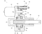
そこで、例えば、電動モータにブレーキ手段を設けたり、あるいは伝達手段としてウオームギアのような低効率なものを設けることがなされているが、その代表的なものとして、図4に示すような電動リニアアクチュエータが知られている。この電動リニアアクチュエータ50は、回転運動を直線運動に変換するボールねじ51を備えたアクチュエータ本体52と、電動モータ53の回転運動をアクチュエータ本体52に伝達する歯車減速機構54と、歯車減速機構54を構成する第1歯車55に係合してアクチュエータ本体52を位置保持する位置保持機構56とを備えている。
ボールねじ51は、外周面に螺旋状のねじ溝57aが形成され、出力軸としてのねじ軸57と、このねじ軸57に外嵌され、内周面に螺旋状のねじ溝58aが形成されたナット58と、対向する両ねじ溝57a、58aによって形成された転動路に転動自在に収容された多数のボール59とを備えている。
アクチュエータ本体52は、ハウジング60の内周に、ナット58が一対の玉軸受61、62を介して回転自在に支持されると共に、ねじ軸57が、ハウジング60に対して相対回転不能で、かつ軸方向に移動自在に支持されている。そして、ナット58が歯車減速機構54を介して回転駆動されることにより、ねじ軸57が直線運動に変換される。
歯車減速機構54は、電動モータ53のモータ軸53aに固定された小径の平歯車からなる第1歯車55と、この第1歯車55に噛合し、ナット58の外周に一体に形成された大径の平歯車からなる第2歯車63とから構成されている。
位置保持機構56は、第1歯車55に対して係脱自在に設けられているロック部材としてのシャフト64と、このシャフト64を第1歯車55に対して係脱する方向に駆動する駆動手段としてのソレノイド65とを備えている。シャフト64は棒状をなし、ソレノイド65によって直線駆動され、その先端部が受部66に係脱するようになっている。このように、ソレノイド65を制御することにより、シャフト64が第1歯車55に係合して回転が阻止されるので、振動荷重が作用した場合においても、係合面が滑ることなく安定してアクチュエータ本体52のねじ軸57を位置保持することができる(例えば、特許文献1参照。)。
然しながら、こうした従来の電動リニアアクチュエータ50では、その使用箇所によっては、外部から泥水やオイルの浸入や、内部に充填されたグリース飛散防止のため、ボールねじ51等の駆動部品は、ハウジング60に内蔵されている。特に、この種の第1歯車55と第2歯車63の二段以上の歯車で構成された歯車減速機構54を備えた電動リニアアクチュエータ50では、組立性の面から、二分割のハウジング60構造になっている。
この場合、加工コストアップだけでなく、ハウジング60の締結による部品点数増加や組立工数増加によるコストアップ、あるいは、ハウジング60の質量アップ等の課題がある。
本発明は、こうした従来技術の問題点に鑑みてなされたものであり、部品点数を削減し、簡素な構造による軽量化と共に、組立工数を軽減して低コスト化を図った電動リニアアクチュエータを提供することを目的とする。
係る目的を達成すべく、本発明のうち請求項1に記載の発明は、円板状のブラケットと、このブラケットに取り付けられた電動モータと、この電動モータの回転力をモータ軸を介して伝達する減速機構と、この減速機構を介して前記電動モータの回転運動を駆動軸の軸方向の直線運動に変換するボールねじ機構とを備え、このボールねじ機構が、前記ブラケットに装着された支持軸受を介して回転可能に、かつ軸方向移動不可に支持され、内周に螺旋状のねじ溝が形成されたナットと、このナットに多数のボールを介して内挿され、前記駆動軸と同軸状に一体化されて外周に前記ナットのねじ溝に対応する螺旋状のねじ溝が形成され、前記ブラケットに対して回転不可に、かつ軸方向移動可能に支持されたねじ軸とで構成された電動リニアアクチュエータにおいて、前記減速機構とボールねじ機構が前記ブラケットに組み付けられると共に、このブラケットにカップ状のカバーが着脱可能に装着され、前記ボールねじ機構が当該カバーによって外部から密封されている。
このように、円板状のブラケットと、このブラケットに取り付けられた電動モータと、この電動モータの回転力をモータ軸を介して伝達する減速機構と、この減速機構を介して前記電動モータの回転運動を駆動軸の軸方向の直線運動に変換するボールねじ機構とを備え、このボールねじ機構が、ブラケットに装着された支持軸受を介して回転可能に、かつ軸方向移動不可に支持され、内周に螺旋状のねじ溝が形成されたナットと、このナットに多数のボールを介して内挿され、駆動軸と同軸状に一体化されて外周にナットのねじ溝に対応する螺旋状のねじ溝が形成され、ブラケットに対して回転不可に、かつ軸方向移動可能に支持されたねじ軸とで構成された電動リニアアクチュエータにおいて、減速機構とボールねじ機構がブラケットに組み付けられると共に、このブラケットにカップ状のカバーが着脱可能に装着され、ボールねじ機構が当該カバーによって外部から密封されているので、ボールねじ機構の内部に充填されたグリースの外部への漏洩と、外部から泥水やオイル等が浸入するのを確実に防止することができ、駆動部品が二分割されたハウジングに装着されている従来に比べ、ハウジングの締結による部品点数増加や組立工数増加によるコストアップ、あるいは、ハウジングの質量アップを抑えることができ、部品点数を削減し、簡素な構造による軽量化と共に、組立工数を軽減して低コスト化を図った電動リニアアクチュエータを提供することができる。
また、請求項2に記載の発明のように、前記電動モータが前記カバーによって外部から密封されていても良い。
好ましくは、請求項3に記載の発明のように、前記カバーが、熱可塑性の合成樹脂で射出成形によって形成され、開口端部に径方向に突出した係止部を備えると共に、前記ブラケットに環状溝が形成され、この環状溝に前記カバーの係止部が係止され、当該カバーが弾性変形した状態で装着されていれば、カバーをワンタッチでブラケットに装着することができ、部品点数増加や組立工数増加によるコストアップ、あるいは、ハウジングの質量アップを抑えることができ、部品点数を削減し、簡素な構造による軽量化と共に、組立工数を軽減して低コスト化を図ることができる。
また、請求項4に記載の発明のように、前記係止部が、周方向に少なくとも3個形成されていれば、所望の引抜耐力を確保することができ、カバーの着脱性が向上する。
また、請求項5に記載の発明のように、前記ブラケットが、前記減速機構を構成する入力歯車を収容する第1の取付穴と、前記ボールねじ機構を構成するナットを収容する第2の取付穴を備え、この第2の取付穴に前記支持軸受が装着されていれば、軽量・コンパクト化を図ることができる。
また、請求項6に記載の発明のように、前記ブラケットの両端面が平坦に形成され、一方の端面が相手取付部品の取付面となり、密着した状態で接合されると共に、他方の端面に前記カバーが装着されていれば、構造が簡素になって軽量化を図ることができる。
また、請求項7に記載の発明のように、前記ブラケットがアルミ合金で形成されていれば、軽量化を図ることができる。
また、請求項8に記載の発明のように、前記電動モータとボールねじ機構の組立挿入方向が同じ方向に設定されていれば、組立作業を簡便化することができ、組立作業性を向上させることができる。
また、請求項9に記載の発明のように、前記ナットの外周にキーを介して前記減速機構を構成する出力歯車が一体に固定されると共に、前記ナットの一端部にフランジが形成され、このフランジと前記出力歯車によって前記支持軸受が挟持された状態で外嵌固定されていれば、ナットを単一の支持軸受によってブラケットに対して、回転自在に、かつ軸方向移動不可に安定して支承することができる。
好ましくは、請求項10に記載の発明のように、前記ナットのフランジの位置が前記入力歯車と電動モータのサブアッシーと同じ方向に設定されていれば、電動モータとボールねじ機構の組立挿入方向を同じ方向にすることができ、組立作業を簡便化することができる。
また、請求項11に記載の発明のように、前記支持軸受が4点接触玉軸受で構成されていれば、軸方向のガタを可及的に規制することができる。
本発明に係る電動リニアアクチュエータは、円板状のブラケットと、このブラケットに取り付けられた電動モータと、この電動モータの回転力をモータ軸を介して伝達する減速機構と、この減速機構を介して前記電動モータの回転運動を駆動軸の軸方向の直線運動に変換するボールねじ機構とを備え、このボールねじ機構が、前記ブラケットに装着された支持軸受を介して回転可能に、かつ軸方向移動不可に支持され、内周に螺旋状のねじ溝が形成されたナットと、このナットに多数のボールを介して内挿され、前記駆動軸と同軸状に一体化されて外周に前記ナットのねじ溝に対応する螺旋状のねじ溝が形成され、前記ブラケットに対して回転不可に、かつ軸方向移動可能に支持されたねじ軸とで構成された電動リニアアクチュエータにおいて、前記減速機構とボールねじ機構が前記ブラケットに組み付けられると共に、このブラケットにカップ状のカバーが着脱可能に装着され、前記ボールねじ機構が当該カバーによって外部から密封されているので、ボールねじ機構の内部に充填されたグリースの外部への漏洩と、外部から泥水やオイル等が浸入するのを確実に防止することができ、駆動部品が二分割されたハウジングに装着されている従来に比べ、ハウジングの締結による部品点数増加や組立工数増加によるコストアップ、あるいは、ハウジングの質量アップを抑えることができ、部品点数を削減し、簡素な構造による軽量化と共に、組立工数を軽減して低コスト化を図った電動リニアアクチュエータを提供することができる。
アルミ合金製の円板状のブラケットと、このブラケットに取り付けられた電動モータと、この電動モータの回転力をモータ軸を介して伝達する減速機構と、この減速機構を介して前記電動モータの回転運動を駆動軸の軸方向の直線運動に変換するボールねじ機構とを備え、このボールねじ機構が、前記ブラケットに装着された支持軸受を介して回転可能に、かつ軸方向移動不可に支持され、内周に螺旋状のねじ溝が形成されたナットと、このナットに多数のボールを介して内挿され、前記駆動軸と同軸状に一体化されて外周に前記ナットのねじ溝に対応する螺旋状のねじ溝が形成され、前記ブラケットに対して回転不可に、かつ軸方向移動可能に支持されたねじ軸とで構成された電動リニアアクチュエータにおいて、前記減速機構とボールねじ機構が前記ブラケットに組み付けられ、このブラケットにカップ状のカバーが着脱可能に装着され、このカバーが、熱可塑性の合成樹脂で射出成形によって形成され、開口端部に径方向に突出した係止部を備えると共に、前記ブラケットに環状溝が形成され、この環状溝に前記カバーの係止部が係止され、当該カバーが弾性変形した状態で装着され、少なくとも前記ボールねじ機構が外部から密封されている。
以下、本発明の実施の形態を図面に基づいて詳細に説明する。
図1(a)は、本発明に係る電動リニアアクチュエータの第1の実施形態を示す縦断面図、(b)は、(a)の樹脂カバーの装着部を示す要部拡大図、図2は、図1のボールねじ機構を示す縦断面図である。
図1(a)は、本発明に係る電動リニアアクチュエータの第1の実施形態を示す縦断面図、(b)は、(a)の樹脂カバーの装着部を示す要部拡大図、図2は、図1のボールねじ機構を示す縦断面図である。
この電動リニアアクチュエータ1は、図1(a)に示すように、A6063TEやADC12等のアルミ合金からなるブラケット2と、このブラケット2に取り付けられた電動モータ3と、この電動モータ3のモータ軸3aに取付けられた入力歯車4と、この入力歯車4に噛合する出力歯車5とからなる減速機構6と、この減速機構6を介して電動モータ3の回転運動を駆動軸7の軸方向の直線運動に変換するボールねじ機構8を備えている。
ブラケット2は円板状に形成され、入力歯車4を収容する第1の取付穴2aと、ボールねじ機構8を構成するナット12を収容する第2の取付穴2bを備えている。第1の取付穴2aには電動モータ3が取り付けられると共に、第2の取付穴2bには、ナット12を回転自在に支承する支持軸受18が装着されている。ブラケット2の両端面は平坦に形成され、一方の端面は相手取付部品9の取付面となり、密着した状態で接合されている。
電動モータ3のモータ軸3aは、その端部に平歯車からなる入力歯車4が圧入により相対回転不能に取り付けられ、平歯車からなる出力歯車5に噛合している。この出力歯車5は、後述するボールねじ機構8を構成するナット12にキー13を介して一体に固定されている。
駆動軸7は、ボールねじ機構8を構成するねじ軸10と一体に構成され、相手取付部品9に装着されたオイルシール11により、回転不可に、かつ軸方向移動可能に支持されている。電動モータ3の回転トルクは、入力歯車4から出力歯車5によって減速されてナット12に伝達され、ボールねじ機構8によって駆動軸7の直線運動に変換される。
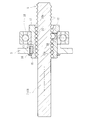
ボールねじ機構8は、図2に拡大して示すように、ねじ軸10と、このねじ軸10にボール14を介して外挿されたナット12とを備えている。ねじ軸10は、外周に螺旋状のねじ溝10aが形成されている。一方、ナット12は、ねじ軸10に外挿されると共に、内周にねじ軸10のねじ溝10aに対応する螺旋状のねじ溝12aが形成されている。そして、これらねじ溝10a、12aとの間に多数のボール14が転動自在に収容されている。ナット12は、外周にキー溝15が形成され、このキー溝15に係止されたキー13を介して出力歯車5が一体に固定されると共に、止め輪16によって軸方向に位置決めされている。
また、ナット12の一端部にはフランジ17が形成され、このフランジ17と出力歯車5によって挟持された状態で支持軸受18が外嵌固定されている。支持軸受18は、ブラケット2の第2の取付穴2bに装着され、止め輪19によって軸方向に位置決め固定されている。この支持軸受18を介して、ナット12がブラケット2に対して、回転自在に、かつ軸方向移動不可に支承されている(図1(a)参照)。支持軸受18は、密封型の深溝玉軸受でも良いが、ここでは、軸方向のガタを可及的に規制することができる4点接触玉軸受が好ましい。20は、ナット12のねじ溝12aを連結して循環部材を構成する駒部材で、この駒部材20によって多数のボール14が無限循環することができる。
各ねじ溝10a、12aの断面形状は、サーキュラアーク形状であってもゴシックアーク形状であっても良いが、ここではボール14との接触角が大きくとれ、アキシアルすきまが小さく設定できるゴシックアーク形状に形成されている。これにより、軸方向荷重に対する剛性が高くなり、かつ振動の発生を抑制することができる。
ナット12はSCM415やSCM420等の肌焼き鋼からなり、真空浸炭焼入れによってその表面に55~62HRCの範囲に硬化処理が施されている。これにより、熱処理後のスケール除去のためのバフ加工等を省略することができ、低コスト化を図ることができる。一方、ねじ軸10はS55C等の中炭素鋼あるいはSCM415やSCM420等の肌焼き鋼からなり、高周波焼入れ、あるいは浸炭焼入れによってその表面に55~62HRCの範囲に硬化処理が施されている。
また、本実施形態では、入力歯車4と電動モータ3のサブアッシーとナット12のフランジ17の位置を同じ方向に揃えることにより、電動モータ3とボールねじ機構8の組立挿入方向を同じ方向にし、組立作業を簡便化することができ、組立作業性を向上させることができる。
ここで、図1(a)に示すように、ボールねじ機構8と電動モータ3等の駆動部品は全てブラケット2に組み付けられていると共に、これら駆動部品は、樹脂カバー21によって密封されている。この樹脂カバー21は、GF(グラス繊維)等の繊維状強化材が所定量充填されたPA(ポリアミド)66等の熱可塑性の合成樹脂で射出成形によって形成され、開口端部に内径側に突出した係止部22を備えている。なお、この係止部22は、全周に形成される環状突起に限らず、周方向に少なくとも3個形成されていれば良い。これにより、所望の引抜耐力を確保することができると共に、樹脂カバー21の着脱性が向上する。
図1(b)に拡大して示すように、ブラケット2の外径面には環状溝23が形成され、この環状溝23に樹脂カバー21の係止部22が弾性変形した状態、所謂スナップフィット構造によって装着されている。このように、本実施形態では、駆動部品が円板状のブラッケト2に全て装着されていると共に、このブラケット2にカップ状の樹脂カバー21が着脱可能に装着され、駆動部品がこの樹脂カバー21によって外部から密封されているため、内部に充填されたグリースの外部への漏洩と、外部から泥水やオイル等が浸入するのを確実に防止することができる。さらに、樹脂カバー21をワンタッチでブラケット2に装着することができるため、駆動部品が二分割されたハウジングに装着されている従来に比べ、ハウジングの締結による部品点数増加や組立工数増加によるコストアップ、あるいは、ハウジングの質量アップを抑えることができ、部品点数を削減し、簡素な構造による軽量化と共に、組立工数を軽減して低コスト化を図った電動リニアアクチュエータを提供することができる。
図3(a)は、本発明に係る電動リニアアクチュエータの第2の実施形態を示す縦断面図、(b)は、(a)の樹脂カバーの装着部を示す要部拡大図である。なお、この実施形態は、前述したものと基本的には、樹脂カバーの構成が異なるだけで、その他前述した実施形態と同一部品同一部位あるいは同様の機能を有する部品や部位には同じ符合を付して詳細な説明を省略する。
この電動リニアアクチュエータ24は、図3(a)に示すように、アルミ合金からなるブラケット25と、このブラケット25に取り付けられた電動モータ3と、この電動モータ3のモータ軸3aに取付けられた入力歯車4と、この入力歯車4に噛合する出力歯車5からなる減速機構6と、この減速機構6を介して電動モータの回転運動を駆動軸7の軸方向の直線運動に変換するボールねじ機構8とを備えている。
ブラケット25は円板状に形成され、入力歯車4を収容する第1の取付穴2aと、ボールねじ機構8を構成するナット12を収容する第2の取付穴25aを備えている。この第2の取付穴25aには、ブラケット25に対してナット12を回転自在に支承する支持軸受18が装着されている。
ここで、ボールねじ機構8と電動モータ3等の駆動部品は全てブラケット25に組み付けられていると共に、これら駆動部品のうちボールねじ機構8が、樹脂カバー26によって密封されている。この樹脂カバー26は、GF等の繊維状強化材が所定量充填されたPA66等の熱可塑性の合成樹脂で射出成形によって形成され、開口端部に外径側に突出した環状の係止部27を備えている。
図3(b)に拡大して示すように、ブラケット25の第2の取付穴25aには環状溝28が形成され、この環状溝28に樹脂カバー26の係止部27が弾性変形した状態で装着されている。このように、本実施形態では、駆動部品が円板状のブラッケト25に全て装着されていると共に、ボールねじ機構8が樹脂カバー26によって外部から密封されているため、内部に充填されたグリースの外部への漏洩と、外部から泥水やオイル等が浸入するのを確実に防止することができる。さらに、樹脂カバー26をワンタッチでブラケット25に装着することができるため、前述した実施形態と同様、駆動部品が二分割されたハウジングに装着されている従来に比べ、ハウジングの締結による部品点数増加や組立工数増加によるコストアップ、あるいは、ハウジングの質量アップを抑えることができ、部品点数を削減し、簡素な構造による軽量化と共に、組立工数を軽減して低コスト化を図ることができる。
以上、本発明の実施の形態について説明を行ったが、本発明はこうした実施の形態に何等限定されるものではなく、あくまで例示であって、本発明の要旨を逸脱しない範囲内において、さらに種々なる形態で実施し得ることは勿論のことであり、本発明の範囲は、特許請求の範囲の記載によって示され、さらに特許請求の範囲に記載の均等の意味、および範囲内のすべての変更を含む。
本発明に係る電動リニアアクチュエータは、一般産業用の電動機、自動車等の駆動部に使用され、電動モータからの回転入力を、ボールねじ機構を介して駆動軸の直線運動に変換するボールねじ機構を備えた電動リニアアクチュエータに適用できる。
1、24 電動リニアアクチュエータ
2、25 ブラケット
2a 第1の取付穴
2b、25a 第2の取付穴
3 電動モータ
3a モータ軸
4 入力歯車
5 出力歯車
6 減速機構
7 駆動軸
8 ボールねじ機構
9 相手取付部材
10 ねじ軸
10a、12a ねじ溝
11 オイルシール
12 ナット
13 キー
14 ボール
15 キー溝
16、19 止め輪
17 フランジ
18 支持軸受
20 駒部材
21、26 樹脂カバー
22、27 係止部
23、28 環状溝
50 電動リニアアクチュエータ
51 ボールねじ
52 アクチュエータ本体
53 電動モータ
53a モータ軸
54 歯車減速機構
55 第1歯車
56 位置保持機構
57 ねじ軸
57a、58a ねじ溝
58 ナット
59 ボール
60 ハウジング
61、62 玉軸受
63 第2歯車
64 シャフト
65 ソレノイド
66 受部
2、25 ブラケット
2a 第1の取付穴
2b、25a 第2の取付穴
3 電動モータ
3a モータ軸
4 入力歯車
5 出力歯車
6 減速機構
7 駆動軸
8 ボールねじ機構
9 相手取付部材
10 ねじ軸
10a、12a ねじ溝
11 オイルシール
12 ナット
13 キー
14 ボール
15 キー溝
16、19 止め輪
17 フランジ
18 支持軸受
20 駒部材
21、26 樹脂カバー
22、27 係止部
23、28 環状溝
50 電動リニアアクチュエータ
51 ボールねじ
52 アクチュエータ本体
53 電動モータ
53a モータ軸
54 歯車減速機構
55 第1歯車
56 位置保持機構
57 ねじ軸
57a、58a ねじ溝
58 ナット
59 ボール
60 ハウジング
61、62 玉軸受
63 第2歯車
64 シャフト
65 ソレノイド
66 受部
Claims (11)
- 円板状のブラケットと、
このブラケットに取り付けられた電動モータと、
この電動モータの回転力をモータ軸を介して伝達する減速機構と、
この減速機構を介して前記電動モータの回転運動を駆動軸の軸方向の直線運動に変換するボールねじ機構とを備え、
このボールねじ機構が、前記ブラケットに装着された支持軸受を介して回転可能に、かつ軸方向移動不可に支持され、内周に螺旋状のねじ溝が形成されたナットと、
このナットに多数のボールを介して内挿され、前記駆動軸と同軸状に一体化されて外周に前記ナットのねじ溝に対応する螺旋状のねじ溝が形成され、前記ブラケットに対して回転不可に、かつ軸方向移動可能に支持されたねじ軸とで構成された電動リニアアクチュエータにおいて、
前記減速機構とボールねじ機構が前記ブラケットに組み付けられると共に、このブラケットにカップ状のカバーが着脱可能に装着され、前記ボールねじ機構が当該カバーによって外部から密封されていることを特徴とする電動リニアアクチュエータ。 - 前記電動モータが前記カバーによって外部から密封されている請求項1に記載の電動リニアアクチュエータ。
- 前記カバーが、熱可塑性の合成樹脂で射出成形によって形成され、開口端部に径方向に突出した係止部を備えると共に、前記ブラケットに環状溝が形成され、この環状溝に前記カバーの係止部が係止され、当該カバーが弾性変形した状態で装着されている請求項1または2に記載の電動リニアアクチュエータ。
- 前記係止部が、周方向に少なくとも3個形成されている請求項3に記載の電動リニアアクチュエータ。
- 前記ブラケットが、前記減速機構を構成する入力歯車を収容する第1の取付穴と、前記ボールねじ機構を構成するナットを収容する第2の取付穴を備え、この第2の取付穴に前記支持軸受が装着されている請求項1に記載の電動リニアアクチュエータ。
- 前記ブラケットの両端面が平坦に形成され、一方の端面が相手取付部品の取付面となり、密着した状態で接合されると共に、他方の端面に前記カバーが装着されている請求項1に記載の電動リニアアクチュエータ。
- 前記ブラケットがアルミ合金で形成されている請求項1に記載の電動リニアアクチュエータ。
- 前記電動モータとボールねじ機構の組立挿入方向が同じ方向に設定されている請求項1に記載の電動リニアアクチュエータ。
- 前記ナットの外周にキーを介して前記減速機構を構成する出力歯車が一体に固定されると共に、前記ナットの一端部にフランジが形成され、このフランジと前記出力歯車によって前記支持軸受が挟持された状態で外嵌固定されている請求項1に記載の電動リニアアクチュエータ。
- 前記ナットのフランジの位置が前記入力歯車と電動モータのサブアッシーと同じ方向に設定されている請求項9に記載の電動リニアアクチュエータ。
- 前記支持軸受が4点接触玉軸受で構成されている請求項1に記載の電動リニアアクチュエータ。
Applications Claiming Priority (2)
| Application Number | Priority Date | Filing Date | Title |
|---|---|---|---|
| JP2011-170944 | 2011-08-04 | ||
| JP2011170944A JP5719717B2 (ja) | 2011-08-04 | 2011-08-04 | 電動リニアアクチュエータ |
Publications (1)
| Publication Number | Publication Date |
|---|---|
| WO2013018906A1 true WO2013018906A1 (ja) | 2013-02-07 |
Family
ID=47629419
Family Applications (1)
| Application Number | Title | Priority Date | Filing Date |
|---|---|---|---|
| PCT/JP2012/069909 Ceased WO2013018906A1 (ja) | 2011-08-04 | 2012-08-03 | 電動リニアアクチュエータ |
Country Status (2)
| Country | Link |
|---|---|
| JP (1) | JP5719717B2 (ja) |
| WO (1) | WO2013018906A1 (ja) |
Cited By (6)
| Publication number | Priority date | Publication date | Assignee | Title |
|---|---|---|---|---|
| CN109290819A (zh) * | 2018-11-15 | 2019-02-01 | 宝鸡忠诚机床股份有限公司 | 一种轴类加工数控托架 |
| CN109906542A (zh) * | 2016-10-31 | 2019-06-18 | Ntn株式会社 | 电动致动器 |
| CN109915559A (zh) * | 2017-12-13 | 2019-06-21 | 中国科学院沈阳自动化研究所 | 一种短型水下电动直线缸机构 |
| CN110566662A (zh) * | 2018-06-06 | 2019-12-13 | 舍弗勒技术股份两合公司 | 换挡装置及电动汽车 |
| EP3626990B1 (en) * | 2018-09-19 | 2023-08-23 | FTE automotive GmbH | Electric clutch actuator with gear mechanism bearing plate |
| WO2025180569A1 (de) * | 2024-02-29 | 2025-09-04 | Schaeffler Technologies AG & Co. KG | Aktor mit einem e-motor und einem linearantrieb |
Families Citing this family (8)
| Publication number | Priority date | Publication date | Assignee | Title |
|---|---|---|---|---|
| JP6679381B2 (ja) * | 2016-03-30 | 2020-04-15 | Ntn株式会社 | 電動アクチュエータ |
| EP3438505A4 (en) * | 2016-03-30 | 2019-12-18 | NTN Corporation | ELECTRIC ACTUATOR |
| JP6679380B2 (ja) * | 2016-03-30 | 2020-04-15 | Ntn株式会社 | 電動アクチュエータ |
| EP3439150A4 (en) * | 2016-03-30 | 2019-12-18 | NTN Corporation | ELECTRIC ACTUATOR |
| JP6700134B2 (ja) * | 2016-07-21 | 2020-05-27 | Ntn株式会社 | 電動アクチュエータ |
| JP2018074790A (ja) | 2016-10-31 | 2018-05-10 | Ntn株式会社 | 電動アクチュエータ |
| KR101940408B1 (ko) * | 2017-07-26 | 2019-01-21 | 주식회사평화발레오 | 변속기의 파킹 락 액츄에이터 |
| DE102019113825B3 (de) * | 2019-05-23 | 2020-11-26 | ECO Holding 1 GmbH | Aktuator und Verfahren zum Herstellen eines Aktuators |
Citations (5)
| Publication number | Priority date | Publication date | Assignee | Title |
|---|---|---|---|---|
| JP3027795U (ja) * | 1996-02-09 | 1996-08-13 | 株式会社タック技研工業 | 電動シリンダ |
| JP2000294614A (ja) * | 1999-04-07 | 2000-10-20 | Murata Mach Ltd | 物品移載装置 |
| JP2001119892A (ja) * | 1999-10-14 | 2001-04-27 | Hiwin Mikrosystem Corp | 滑出止め式リニアスクリューアクチュエータ |
| JP2002101604A (ja) * | 2000-09-19 | 2002-04-05 | Asmo Co Ltd | モータ |
| JP2004028169A (ja) * | 2002-06-24 | 2004-01-29 | Smc Corp | 電動アクチュエータ |
-
2011
- 2011-08-04 JP JP2011170944A patent/JP5719717B2/ja not_active Expired - Fee Related
-
2012
- 2012-08-03 WO PCT/JP2012/069909 patent/WO2013018906A1/ja not_active Ceased
Patent Citations (5)
| Publication number | Priority date | Publication date | Assignee | Title |
|---|---|---|---|---|
| JP3027795U (ja) * | 1996-02-09 | 1996-08-13 | 株式会社タック技研工業 | 電動シリンダ |
| JP2000294614A (ja) * | 1999-04-07 | 2000-10-20 | Murata Mach Ltd | 物品移載装置 |
| JP2001119892A (ja) * | 1999-10-14 | 2001-04-27 | Hiwin Mikrosystem Corp | 滑出止め式リニアスクリューアクチュエータ |
| JP2002101604A (ja) * | 2000-09-19 | 2002-04-05 | Asmo Co Ltd | モータ |
| JP2004028169A (ja) * | 2002-06-24 | 2004-01-29 | Smc Corp | 電動アクチュエータ |
Cited By (8)
| Publication number | Priority date | Publication date | Assignee | Title |
|---|---|---|---|---|
| CN109906542A (zh) * | 2016-10-31 | 2019-06-18 | Ntn株式会社 | 电动致动器 |
| EP3534502A4 (en) * | 2016-10-31 | 2020-06-03 | NTN Corporation | ELECTRIC ACTUATOR |
| CN109915559A (zh) * | 2017-12-13 | 2019-06-21 | 中国科学院沈阳自动化研究所 | 一种短型水下电动直线缸机构 |
| CN110566662A (zh) * | 2018-06-06 | 2019-12-13 | 舍弗勒技术股份两合公司 | 换挡装置及电动汽车 |
| EP3626990B1 (en) * | 2018-09-19 | 2023-08-23 | FTE automotive GmbH | Electric clutch actuator with gear mechanism bearing plate |
| CN109290819A (zh) * | 2018-11-15 | 2019-02-01 | 宝鸡忠诚机床股份有限公司 | 一种轴类加工数控托架 |
| CN109290819B (zh) * | 2018-11-15 | 2024-03-19 | 宝鸡忠诚机床股份有限公司 | 一种轴类加工数控托架 |
| WO2025180569A1 (de) * | 2024-02-29 | 2025-09-04 | Schaeffler Technologies AG & Co. KG | Aktor mit einem e-motor und einem linearantrieb |
Also Published As
| Publication number | Publication date |
|---|---|
| JP2013038846A (ja) | 2013-02-21 |
| JP5719717B2 (ja) | 2015-05-20 |
Similar Documents
| Publication | Publication Date | Title |
|---|---|---|
| JP5719717B2 (ja) | 電動リニアアクチュエータ | |
| CN103946587B (zh) | 电动线性致动器 | |
| JP5897874B2 (ja) | 電動リニアアクチュエータ | |
| JP6091148B2 (ja) | 電動リニアアクチュエータ | |
| CN104813072B (zh) | 电动线性致动器 | |
| JP6111078B2 (ja) | 電動リニアアクチュエータ | |
| JP2013104525A5 (ja) | ||
| WO2013191066A1 (ja) | 電動リニアアクチュエータ | |
| JP6111043B2 (ja) | 電動リニアアクチュエータ | |
| WO2016080513A1 (ja) | 歯車およびこれを備えた電動アクチュエータ | |
| WO2014192760A1 (ja) | 電動リニアアクチュエータ | |
| JP5924899B2 (ja) | 電動リニアアクチュエータ | |
| JP6114548B2 (ja) | 電動リニアアクチュエータ | |
| JP2012039765A (ja) | 電動アクチュエータ | |
| JP6039748B1 (ja) | 電動アクチュエータ | |
| JP6312728B2 (ja) | 電動リニアアクチュエータ | |
| JP6111038B2 (ja) | 電動リニアアクチュエータ | |
| JP2014037854A (ja) | 電動リニアアクチュエータ | |
| JP6121760B2 (ja) | 電動リニアアクチュエータ | |
| JP6111041B2 (ja) | 電動リニアアクチュエータ | |
| JP6130235B2 (ja) | 電動リニアアクチュエータ | |
| CN113335370B (zh) | 汽车转向机及包括其的汽车 | |
| JP2008069793A (ja) | 電動リニアアクチュエータ |
Legal Events
| Date | Code | Title | Description |
|---|---|---|---|
| 121 | Ep: the epo has been informed by wipo that ep was designated in this application |
Ref document number: 12820115 Country of ref document: EP Kind code of ref document: A1 |
|
| NENP | Non-entry into the national phase |
Ref country code: DE |
|
| 122 | Ep: pct application non-entry in european phase |
Ref document number: 12820115 Country of ref document: EP Kind code of ref document: A1 |