WO2013015250A1 - 車両用灯具 - Google Patents
車両用灯具 Download PDFInfo
- Publication number
- WO2013015250A1 WO2013015250A1 PCT/JP2012/068609 JP2012068609W WO2013015250A1 WO 2013015250 A1 WO2013015250 A1 WO 2013015250A1 JP 2012068609 W JP2012068609 W JP 2012068609W WO 2013015250 A1 WO2013015250 A1 WO 2013015250A1
- Authority
- WO
- WIPO (PCT)
- Prior art keywords
- light
- surface portion
- cavity
- emitting element
- vehicle lamp
- Prior art date
- Legal status (The legal status is an assumption and is not a legal conclusion. Google has not performed a legal analysis and makes no representation as to the accuracy of the status listed.)
- Ceased
Links
Images



Classifications
-
- F—MECHANICAL ENGINEERING; LIGHTING; HEATING; WEAPONS; BLASTING
- F21—LIGHTING
- F21S—NON-PORTABLE LIGHTING DEVICES; SYSTEMS THEREOF; VEHICLE LIGHTING DEVICES SPECIALLY ADAPTED FOR VEHICLE EXTERIORS
- F21S43/00—Signalling devices specially adapted for vehicle exteriors, e.g. brake lamps, direction indicator lights or reversing lights
- F21S43/40—Signalling devices specially adapted for vehicle exteriors, e.g. brake lamps, direction indicator lights or reversing lights characterised by the combination of reflectors and refractors
-
- F—MECHANICAL ENGINEERING; LIGHTING; HEATING; WEAPONS; BLASTING
- F21—LIGHTING
- F21S—NON-PORTABLE LIGHTING DEVICES; SYSTEMS THEREOF; VEHICLE LIGHTING DEVICES SPECIALLY ADAPTED FOR VEHICLE EXTERIORS
- F21S43/00—Signalling devices specially adapted for vehicle exteriors, e.g. brake lamps, direction indicator lights or reversing lights
- F21S43/10—Signalling devices specially adapted for vehicle exteriors, e.g. brake lamps, direction indicator lights or reversing lights characterised by the light source
- F21S43/13—Signalling devices specially adapted for vehicle exteriors, e.g. brake lamps, direction indicator lights or reversing lights characterised by the light source characterised by the type of light source
- F21S43/15—Strips of light sources
-
- F—MECHANICAL ENGINEERING; LIGHTING; HEATING; WEAPONS; BLASTING
- F21—LIGHTING
- F21S—NON-PORTABLE LIGHTING DEVICES; SYSTEMS THEREOF; VEHICLE LIGHTING DEVICES SPECIALLY ADAPTED FOR VEHICLE EXTERIORS
- F21S43/00—Signalling devices specially adapted for vehicle exteriors, e.g. brake lamps, direction indicator lights or reversing lights
- F21S43/20—Signalling devices specially adapted for vehicle exteriors, e.g. brake lamps, direction indicator lights or reversing lights characterised by refractors, transparent cover plates, light guides or filters
-
- F—MECHANICAL ENGINEERING; LIGHTING; HEATING; WEAPONS; BLASTING
- F21—LIGHTING
- F21S—NON-PORTABLE LIGHTING DEVICES; SYSTEMS THEREOF; VEHICLE LIGHTING DEVICES SPECIALLY ADAPTED FOR VEHICLE EXTERIORS
- F21S43/00—Signalling devices specially adapted for vehicle exteriors, e.g. brake lamps, direction indicator lights or reversing lights
- F21S43/20—Signalling devices specially adapted for vehicle exteriors, e.g. brake lamps, direction indicator lights or reversing lights characterised by refractors, transparent cover plates, light guides or filters
- F21S43/235—Light guides
- F21S43/236—Light guides characterised by the shape of the light guide
- F21S43/239—Light guides characterised by the shape of the light guide plate-shaped
-
- F—MECHANICAL ENGINEERING; LIGHTING; HEATING; WEAPONS; BLASTING
- F21—LIGHTING
- F21S—NON-PORTABLE LIGHTING DEVICES; SYSTEMS THEREOF; VEHICLE LIGHTING DEVICES SPECIALLY ADAPTED FOR VEHICLE EXTERIORS
- F21S43/00—Signalling devices specially adapted for vehicle exteriors, e.g. brake lamps, direction indicator lights or reversing lights
- F21S43/20—Signalling devices specially adapted for vehicle exteriors, e.g. brake lamps, direction indicator lights or reversing lights characterised by refractors, transparent cover plates, light guides or filters
- F21S43/235—Light guides
- F21S43/242—Light guides characterised by the emission area
- F21S43/245—Light guides characterised by the emission area emitting light from one or more of its major surfaces
-
- F—MECHANICAL ENGINEERING; LIGHTING; HEATING; WEAPONS; BLASTING
- F21—LIGHTING
- F21S—NON-PORTABLE LIGHTING DEVICES; SYSTEMS THEREOF; VEHICLE LIGHTING DEVICES SPECIALLY ADAPTED FOR VEHICLE EXTERIORS
- F21S43/00—Signalling devices specially adapted for vehicle exteriors, e.g. brake lamps, direction indicator lights or reversing lights
- F21S43/30—Signalling devices specially adapted for vehicle exteriors, e.g. brake lamps, direction indicator lights or reversing lights characterised by reflectors
- F21S43/31—Optical layout thereof
- F21S43/315—Optical layout thereof using total internal reflection
-
- F—MECHANICAL ENGINEERING; LIGHTING; HEATING; WEAPONS; BLASTING
- F21—LIGHTING
- F21S—NON-PORTABLE LIGHTING DEVICES; SYSTEMS THEREOF; VEHICLE LIGHTING DEVICES SPECIALLY ADAPTED FOR VEHICLE EXTERIORS
- F21S43/00—Signalling devices specially adapted for vehicle exteriors, e.g. brake lamps, direction indicator lights or reversing lights
- F21S43/10—Signalling devices specially adapted for vehicle exteriors, e.g. brake lamps, direction indicator lights or reversing lights characterised by the light source
- F21S43/13—Signalling devices specially adapted for vehicle exteriors, e.g. brake lamps, direction indicator lights or reversing lights characterised by the light source characterised by the type of light source
- F21S43/14—Light emitting diodes [LED]
Definitions
- the present invention relates to a vehicle lamp including at least one semiconductor element, a front surface member, and a rear surface member, and diffusing light emitted from the light emitting element in a cavity formed between the front surface member and the rear surface member.
- Patent Document 1 a part of light directly incident from the LED is transmitted to the half mirror surface and emitted to the front of the inner lens, and the remaining light is between the half mirror surface of the inner lens and the reflecting surface of the lamp body.
- a vehicle lamp is described which is multi-reflected in the space of (1) and transmits part of light repeatedly incident on the half mirror surface to the inner lens and emits the light forward.
- the half mirror surface of the vehicle lamp of Patent Document 1 and the reflecting surface of the lamp body do not diffuse the reflected light when the light from the LED is multiply reflected in space. Therefore, a part of light emitted to the front of the inner lens after multiple reflection does not emit uniformly to the front. In other words, the inner lens of Patent Document 1 can not emit light uniformly in a planar manner.
- This invention is made in view of the said subject, and it diffuses the emitted light of a light emitting element in the cavity formed between the front surface member and the rear surface member, and it is possible for vehicles to carry out surface light emission uniformly. It provides a lamp.
- the vehicular lamp of the present invention is provided with at least one or more light emitting elements, a first surface, and a front surface of the first surface.
- the cavity side surface of the surface portion is formed as a reflection surface
- the second surface portion is formed in a plate surface shape, has a light transmitting property, and a plurality of adjacent prism type reflection elements on at least the cavity side surface
- the plurality of prism type reflective elements are partially transmitted to the front surface of the light from the light emitting element incident in the cavity, and the other non-transmissive light is transmitted into the cavity. Extending in the first direction and reflecting the multiple reflections, and Is a direction toward the surface is obtained by configured to have a prism shape protruding in the second direction.
- the light from the light emitting element is directly or indirectly incident on the cavity between the first surface portion and the second surface portion via deflection means such as a reflector.
- the reflective element provided on the cavity-side surface of the second surface portion transmits a part of the incident light from the light emitting element to the second surface portion to be emitted forward, and diffusely reflects the remaining light toward the cavity side.
- the light diffusely reflected in the cavity is multiply reflected in the cavity by the reflecting element and the reflecting surface provided on the cavity side surface of the first surface portion, and part of the multiply reflected light is forward from the second surface portion It emits equally. As a result, the second surface emits light evenly.
- the vehicle lamp according to the present invention is the vehicle lamp described in (1) above, wherein the plurality of prism type reflecting elements are orthogonal to the first and second directions, respectively. Adjacent to the direction are arranged to form a prismatic reflecting element group, and a plurality of the prismatic reflecting element groups are provided to be adjacent to the first direction, and each prismatic reflecting element group is an adjacent prism It is preferable that the third reflective element group be disposed offset in the third direction.
- Diffused light by the light emitting element uniformly diffused to the second surface portion is light emitted forward from the formation portion of the prismatic reflection element, and a portion where the prismatic reflection element is not formed, that is, adjacent prismatic reflection elements A light and dark difference is formed between the boundary (hereinafter simply referred to as the boundary). Therefore, if the prismatic reflective elements are arranged in a line in the vertical direction, a vertically long and dark difference is formed between the prismatic reflective elements and the boundary portion.
- the vertically adjacent prism type reflection elements are offset to the left and right (third direction), and the contrast in the vertical direction (second direction) is divided. It makes it difficult to see the difference in direction.
- the vehicle lamp of the present invention is the vehicle lamp according to the above (1) or (2), wherein the projection heights of the plurality of prism type reflecting elements in the second direction are the respective ones.
- each of the prismatic reflective elements is formed substantially uniformly.
- each prismatic reflecting element protrudes in a substantially uniform length in the second direction for each prismatic reflecting element, the light from the light emitting element is diffused and reflected uniformly toward the cavity, whereby the light emitting element Diffuses the light evenly over the entire second surface.
- a vehicle lamp according to the present invention is the vehicle lamp according to any one of the above (1) to (3), characterized in that the first direction and the second direction in each of the prism type reflecting elements Preferably, the ridges of the cross section cut in the cross section including the direction are configured to have a sawtooth shape.
- the sawtooth-shaped reflective element reflects light from the light emitting element to a wider angle toward the cavity, thereby diffusing the light from the light emitting element more evenly over the entire second surface.
- the vehicle lamp according to the present invention is the vehicle lamp according to any one of the above (1) to (4), wherein the second direction and the third direction in each of the prism type reflecting elements are used. It is preferable that the ridgeline of the cross section cut in the cross section including the direction is formed into a substantially triangular shape in which R on the left and right sides of the triangle is attached to the projecting direction.
- the light from the first light emitting element is formed by a curved line which is convex outward instead of a straight line instead of the two sides forming the ridge line of the section cut in the section including the second direction and the third direction. It emits in front of the surface as diffused light. The inside of the second surface portion becomes difficult to see by the diffusion of the light emitted from the second surface portion.
- planar and even light can be formed using the light emitting element. Therefore, it can be used, for example, as a vehicle lamp for tail lamps.
- the second surface portion emits light more uniformly and emits light. Looks better.
- the second surface portion emits light more uniformly.
- the vehicle lamp of (5) has a blinding effect for hiding the inside of the second surface portion.
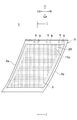
- FIG. 1 is a front view of a first embodiment of a vehicular lamp.
- FIG. 7A is an enlarged partial plan view showing the configuration of the reflective element of the second surface portion, and FIG. 7A is a plan view of the second surface portion viewed from the cavity side.
- (B) (a) Section II-II figure of a figure.
- (C) Front view of 2nd surface part. Optical path explanatory drawing in the cavity of the light from a light emitting element. The figure which shows 2nd Example of the vehicle lamp in which the shapes of a reflection element differ, (a) The expansion partial top view of the 2nd surface part seen from the cavity side.
- B) (a) Section III-III figure of a figure.
- (D) A partial perspective view of the second surface portion. The expanded perspective view of the reflection element of 2nd Example.
- the vehicular lamp 1 comprises a lamp body 2, a transparent or semi-transparent outer lens 3 fixed to the front of the lamp body 2, and a lamp unit 4 disposed inside the lamp body 2.
- the lamp unit 4 has a first light emitting element (LED) 5 and includes a plurality of light emitting element units 6 fixed to the lamp body 2 by fixing means (not shown), a first surface 10 and a second surface 11 And a support member 12 integrally fixing the first and second surface portions (10, 11) to the lamp body 2.
- LED light emitting element
- the lamp main body 2 of FIG. 1 is formed in a box shape, has a shape in which the left and right sides (2a, 2b) are inclined in parallel downward to the left, and the front opening 2c is closed by the outer lens 3.
- the front surface 11 a of the second surface portion 11 of the lamp unit 4 is exposed to the front through the outer lens 3.
- the first surface portion 10 and the second surface portion 11 are formed in a plate surface shape extending in the vertical direction, fixed at the lower end portions (10a, 11b) to the support member 12, and arranged to face each other in a state of being separated longitudinally Ru.
- a cavity 15 is defined between the first surface 10 and the second surface 11.
- the support member 12 is fixed to the lower side of the lamp body 2 by fixing means (not shown).
- the plurality of light emitting element units 6 are fixed to the upper side of the lamp body 2 so as to be equally spaced left and right.
- the first light emitting elements 5 are arranged to face the upper opening 15 a of the cavity 15 respectively.
- the light from the first light emitting element 5 has a predetermined range including the first direction in which the first surface portion and the second surface portion (10, 11) extend (a reflecting surface of the first surface portion 10 shown in FIG. 4)
- the light is incident on the cavity 15 at a certain irradiation range) having a spread in the front, back, left, and right with the vertical direction as the center including the oblique downward direction toward the reflective element 20 of the 19 or the second surface portion 11.
- the light emitted from the light emitting element 5 may be directly incident on the cavity 15 as in the embodiments of the present application, or may be reflected on the separately installed reflector and then incident on the cavity.
- the cavity side surface of the first surface portion 10 is subjected to reflection processing to be formed as a reflection surface 19.
- the color of the reflective surface 19 is desirably white in order to make the reflected light uniform.
- the reflective element 20 has a prism shape extending in a first direction, and a plurality of protrusions are provided in the second direction toward the cavity 15.
- Each reflecting element 20 is formed in a triangular prism shape extending in the vertical direction in FIG. 3A (the top side of the triangular prism that is the ridge of the reflective element is represented by reference numeral 24), and has a boundary 21 (vertical direction) They are arranged adjacent to each other in the left-right direction (third direction) with the thick line portion interposed therebetween.
- the protrusion height h1 in the second direction from the bottom 25 of each reflective element 20 to the ridgeline 24 is substantially uniform.
- each reflective element group 22 is left or right by half the length (L1 / 2) of the lateral width (length L1) of each reflective element 20 with respect to the other reflective element groups 22 disposed above and below it It is offset (displaced) and arranged.
- the boundary portion 21 (thick line portion in the vertical direction) of each of the reflection elements 20 is divided short in the vertical length (length L2) of the reflection element 20 without being connected in a straight line vertically.
- the reflective elements 20 are arranged in a line in the longitudinal direction (vertical direction in FIG. 3A), the light emitting elements 5 diffused in a planar manner in the cavity 15 between the reflective elements 20 and the boundary 21. Due to the light from the center, a long and dark difference is formed. However, in the respective embodiments of the present application, since the boundary portion 21 is divided short, the contrast in the vertical direction is not noticeable.
- the light from the light emitting element 5 which can not transmit the reflective element 20 or the boundary 21 is diffused to the entire second surface 11 by at least one reciprocation between the reflective element 20 and the reflective surface 19 by the reflection and rereflection. (Symbols R2 to R4).
- the light of the light emitting element 5 diffused by multiple reflection is uniformly incident on the second surface portion 11 from the rear and transmitted therethrough, and emits the light forward, thereby uniformly emitting surface light of the entire second surface portion 11.
- the light surface-emitted by the light emitting element 5 is mainly used for a tail lamp or the like.
- the vehicle lamp of the second embodiment is different from the configuration of the vehicle lamp 1 of the first embodiment only in the shape of the reflective element 31 compared to the reflective element 20.
- a plurality of reflecting elements 31 of substantially the same shape formed in the range of reference numerals (31a, 31b, 31h, 31g) in FIG. 5A are provided.
- each reflecting element 31 When viewed from the left direction (third direction) in FIG. 5A, each reflecting element 31 has a triangular shape with each symbol (31a to 31c) as a point, and the horizontal direction of the reflecting element 31 from the boundary portion 32 described later
- the other boundary portion 32 (symbols 31g to 31i) adjacent along the curve convex outward after rising along the curve convex outward to the ridgeline 35 (symbols 31d to 31f) positioned at the center of the )
- Each reflective element 31 has a substantially triangular shape (R is a basic cross-sectional shape of the reflective element 31) as shown in FIG.
- the first projection height h2 in the second direction of the substantially triangular shape (31a, 31g, 31d) is the height from the base connecting the points 31a and 31g to the vertex 31d, as shown in FIG. And FIG. 6) are identical and uniform for each reflective element.
- the second projecting height h3 (the height from the line connecting the points 31d and 31e to the most projecting point 31f of the ridge 35 as shown in FIG. 6) is also the second projecting height h3 of the reflecting element 31 in the second direction. The same and uniform for each reflective element
- the reflective elements 31 are arranged to be adjacent in the left-right direction (third direction) with the boundary 32 (thick line in the vertical direction) interposed therebetween.
- the reflective element groups 33 are arranged in multiple groups adjacent to each other vertically with the boundary portion 34 extending to the left and right. Ru.
- Each of the reflective element groups 33 has a half length (L3 / 2) of the lateral width (length L3) of each reflective element 31 with respect to the other reflective element groups 33 disposed above and below, either in the left or right direction. It is offset (displaced) and arranged.
- the ridge line of the cross section is formed to have a sawtooth shape.
- the sawtooth-shaped ridgeline has a shape in which a ridgeline with a large protrusion length to the cavity 15 and a ridgeline with a small protrusion length are alternately arranged up and down.
- the reflective element 31 is inclined in a sawtooth shape, light emitted forward from the reflective element 31 can be easily emitted in the front direction.
- the boundary 32 (thick line portion in the vertical direction) of each of the reflection elements 31 is divided into the vertical length (length L4) of the reflection element 31 without being connected in a straight line in the vertical direction. Therefore, in the second embodiment, since the boundary portion 32 is divided short, the vertical contrast between the reflective element 31 and the boundary portion 32 is not noticeable.
- the light emitted forward from the reflecting element 31 has a substantially triangular shape with R that the ridge seen from the front has, when the ridge is made a general triangle without R (FIG. 3 (c)) Also, it is easy to be diffused (FIG. 5 (c)). Therefore, in the vehicle lamp of the second embodiment, it is difficult to see the inside of the second surface portion 11. As a result, in the vehicle lamp of the second embodiment, a blinding effect occurs which makes the internal structure difficult to see.
- the ridge line shape of the reflective element 31 as viewed from the left side surface of FIG. 5B is substantially the same as the front shape of FIG. Good. In that case, the diffusivity of the light emitted from the reflective element 31 is further improved, whereby the blinding effect is further improved.
- Vehicle lamp 5: light emitting element
- 10 first surface
- 11 second surface
- 11a front of second surface
- 15 cavity
- 19 reflective surface
- 20 reflective element
- 31 ridgeline Reflective element with sawtooth shape
- F front of lamp
Landscapes
- Engineering & Computer Science (AREA)
- General Engineering & Computer Science (AREA)
- Non-Portable Lighting Devices Or Systems Thereof (AREA)
Abstract
本発明の目的の一つは、前面部材と後面部材との間に形成された空洞内で発光素子の出射光を拡散させ、均一に面発光させることが可能な車両用灯具を提供することである。 車両用灯具(1)において、空洞(15)を形成するようにほぼ対向して配置される第一面部(10)及び第二面部(11)を有し、少なくとも一つ以上設けられた発光素子(5)からの光を前記空洞(15)に所定の範囲で入射させ、第二面部(11)の空洞側表面の少なくとも一部に設けた複数の隣接するプリズム型反射要素(20)と、第一面部(10)の空洞側表面に設けた反射面(19)との間で多重反射させることにより、第二面部(11)全体を均等に面発光させる。
Description
本発明は、少なくとも一つの半導体素子と前面部材と後面部材とを備え、前面部材と後面部材との間に形成された空洞内で発光素子の出射光を拡散させる車両用灯具に関するものである。
特許文献1には、LEDから直接入射した光の一部をハーフミラー面に透過させてインナーレンズの前方に出射し、かつ残る光をインナーレンズのハーフミラー面とランプボディの反射面との間の空間内で多重反射させ、ハーフミラー面に繰り返し入射した光の一部をインナーレンズに透過させて前方に出射させる車両用灯具が記載されている。
特許文献1の車両用灯具のハーフミラー面とランプボディの反射面は、LEDによる光を空間内で多重反射させる際に反射光を拡散させていない。従って、多重反射してからインナーレンズの前方に出射する一部の光は、前方に向けて均等に出射しない。言い換えると、特許文献1のインナーレンズは、面状に均一に発光することが出来ない。
本発明は、上記課題を鑑みてなされたものであり、前面部材と後面部材との間に形成された空洞内で発光素子の出射光を拡散させ、均一に面発光することが可能な車両用灯具を提供するものである。
(1) 前記課題を解決するために、本発明の車両用灯具は、少なくとも一つ以上の発光素子と、第一面部と、前記第一面部の前方にほぼ対向して配置される第二面部と、前記発光素子からの光が前記第一面部及び第二面部の面方向である第一方向を含む所定の範囲で前記空洞に入射される車両用灯具であって、前記第一面部の空洞側表面は、反射面として形成され、前記第二面部は、板面状に形成され、透光性を有し、かつ隣接する複数のプリズム型反射要素をその空洞側表面の少なくとも一部に有し、前記複数のプリズム型反射要素は、空洞内に入射した前記発光素子からの光のうち、一部をその前面に向けて透過させると共に、その他の透過させない光を空洞内へ反射して多重反射させるように、前記第一方向に延出し、かつ前記第一面部に向かう方向である第二方向に突出するプリズム形状を有するように構成したものである。
発光素子による光は、第一面部及び第二面部間の空洞に直接またはリフレクタ等の偏向手段を介し間接的に入射する。第二面部の空洞側表面に設けられた反射要素は、発光素子による入射光の一部を第二面部に透過させて前方に出射させ、残りの光を空洞側に向けて拡散反射させる。空洞内に拡散反射された光は、反射要素と、第一面部の空洞側表面に設けられた反射面によって空洞内で多重反射し、多重反射した光の一部が第二面部から前方に均等に出射する。その結果、第二面部は、均等に面発光する。
(2) また、本発明の車両用灯具は、上記の(1)に記載の車両用灯具であって、前記複数のプリズム型反射要素は、前記第一及び第二方向にそれぞれ直交する第三方向に隣接するように配列されてプリズム型反射要素群を構成し、前記プリズム型反射要素群は、前記第一方向に隣接するよう複数群設けられ、各プリズム型反射要素群は、隣接するプリズム型反射要素群に対して前記第三方向にオフセットして配置されることが好ましい。
第二面部に均等に拡散された発光素子による拡散光は、プリズム型反射要素の形成部分から前方に出射する光と、プリズム型反射要素が形成されていない部分、つまり隣接するプリズム型反射要素の境界部(以降は単に境界部という)との間に明暗差を形成する。従って、仮にプリズム型反射要素を上下に一列に配列した場合には、プリズム型反射要素と、前記境界部との間に縦長の明暗差が形成されてしまう。
しかし、上記の(2)の車両用灯具においては、上下に隣接するプリズム型反射要素が左右(第三方向)にオフセットされ、縦方向(第二方向)の明暗差が分断されるため、縦方向の明暗差が見えにくくなる。
(3) また、本発明の車両用灯具は、上記の(1)または(2)に記載の車両用灯具であって、前記複数のプリズム型反射要素における前記第二方向の突出高さが各プリズム型反射要素毎に略均一に形成されることが好ましい。
各プリズム型反射要素は、各プリズム型反射要素毎に第二方向に向けて略均一な長さで突出するため、発光素子からの光を空洞に向かって均等に拡散反射することにより、発光素子による光を第二面部全体に均等に拡散する。
(4) また、本発明の車両用灯具は、上記の(1)~(3)のうちいずれかに記載の車両用灯具であって、前記各プリズム型反射要素における前記第一方向及び第二方向を含む断面で切断した断面の稜線が鋸歯形状を有するように構成されることが好ましい。
鋸歯形状の反射要素が、発光素子からの光を空洞に向かってより広角度に反射することにより、発光素子による光を第二面部全体に更に均等に拡散する。
(5) また、本発明の車両用灯具は、上記の(1)~(4)のうちいずれかに記載の車両用灯具であって、前記各プリズム型反射要素における前記第二方向及び第三方向を含む断面で切断した断面の稜線が三角形の左右両辺に突出方向のRをつけてなる略三角形状となるように構成されることが好ましい。
第一の発光素子による光は、前記第二方向及び第三方向を含む断面で切断した断面の稜線を構成する二つの辺を直線ではなく外向きに凸となる曲線とすることにより、第二面部の前方に拡散光として出射する。第二面部の内側は、第二面部からの出射光が拡散することによって見えにくくなる。
上記の(1)の車両用灯具によれば、発光素子を用いて面状かつ均等な光を形成することができる。従って、例えば、テールランプ用の車両用灯具として用いることができる。
上記の(2)の車両用灯具によれば、プリズム型反射要素と、該プリズム型反射要素の境界部との間の明暗差が目立たなくなるため、より均等に面発光し、発光する第二面部の見栄えが向上する。
上記の(3)または(4)の車両用灯具によれば、第二面部がより均一に面発光する。
上記の(5)の車両用灯具は、第二面部の内側を隠す目隠し効果を奏する。
[規則91に基づく訂正 27.07.2012]
車両用灯具の第一実施例の正面図。
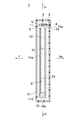
車両用灯具を縦に切断した、図1のI-I断面図。
第二面部の反射要素の構成を示す拡大部分平面図で、(a)空洞側から見た第二面部の平面図。(b)(a)図のII-II断面図。(c)第二面部の正面図。
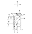
発光素子からの光の空洞内における光路説明図。
反射要素の形状が異なる車両用灯具の第二実施例を示す図で、(a)空洞側から見た第二面部の拡大部分平面図。(b)(a)図のIII-III断面図。(c)第二面部の正面図。(d)第二面部の部分斜視図。
第二実施例の反射要素の拡大斜視図。
まず、図1から図4により本発明における車両用灯具の実施の形態の一例である第一実施例を説明する。車両用灯具1は、ランプ本体2と,ランプ本体2の前面に固定された透明又は半透明のアウターレンズ3と、ランプ本体2の内側に配置された灯具ユニット4とから構成される。灯具ユニット4は、第一の発光素子(LED)5を有し、図示しない固定手段によってランプ本体2に固定された複数の発光素子ユニット6と、第一面部10と、第二面部11と、第一及び第二面部(10,11)を一体化してランプ本体2に固定する支持部材12によって構成される。尚、図1、図3(a)においては、灯具正面から見た各方向を(灯具上方:下方:右方:左方=U:Lo:Ri:Le)として説明し、図2、図3(b)、図4においては、各方向を(灯具前方:後方:上方:下方=F:Re:U:Lo)として説明する。また、図1~図5においては、ランプ本体2の上下方向に沿って第一面部及び第二面部(10,11)が延出する面方向を第一方向とし、後述する第一面部10に向かって突設された反射要素20の突出方向(図3(b)の符号Re方向)を第二方向とし、第一方向及び第二方向に直交する方向を第三方向として説明する。
図1のランプ本体2は、箱形に形成され、左右両面(2a、2b)が平行に左下がりに傾斜する形状を有し、前方の開口部2cがアウターレンズ3によって閉塞される。灯具ユニット4の第二面部11の前面11aは、アウターレンズ3を介して前方に露出される。
第一面部10と第二面部11は、上下に延びる板面形状に形成され、下端部(10a、11b)を支持部材12に固定され、かつ前後に離間した状態で対向するように配置される。第一面部10と第二面部11との間には、空洞15が画成される。支持部材12は、図示しない固定手段によってランプ本体2の下部側に固定される。
複数の発光素子ユニット6は、左右に等間隔となるようにランプ本体2の上部側に固定される。第一の発光素子5は、それぞれ空洞15の上部開口部15aに正対するように配置される。第一の発光素子5からの光は、第一面部及び第二面部(10,11)が延出する第一方向を含む所定の範囲(図4に示される第一面部10の反射面19又は第二面部11の反射要素20へ向かう斜め下方方向も含む、上下方向を中心とし前後左右に広がりをもつ一定の照射範囲)で空洞15に入射する。
尚、発光素子5から出射する光は、本願各実施例のように直接空洞15に入射させても良いし、別途設置したリフレクタを介して反射させてから空洞に入射させても良い。
尚、発光素子5から出射する光は、本願各実施例のように直接空洞15に入射させても良いし、別途設置したリフレクタを介して反射させてから空洞に入射させても良い。
第一面部10の空洞側表面は、反射処理が施され反射面19として形成される。また、反射面19の色は、反射光を均一にするため、望ましくは白色とする。
第二面部11の空洞側表面には、図3(a)の符号20aから20dの範囲に形成される略同一形状の反射要素20が複数設けられる。反射要素20は、第一方向に延出するプリズム形状を有し、かつ空洞15に向かって第二方向に複数突設される。各反射要素20は、図3(a)の上下方向に延びる三角柱形状(反射要素の稜線となる三角柱の頂辺は、符号24で表される)に形成され、かつ境界部21(縦方向の太線部分)を間に挟んで左右方向(第三方向)に隣接するように配列される。各反射要素20の底部25から稜線24までの第二方向への突出高さh1(図3(c)を参照)は、略均一である。
左右に隣接するよう配列された複数の反射要素20を一群の反射要素群22とすると、反射要素群22は、左右に延びる境界部23を間に挟んで上下に隣接するように複数群配置される。各反射要素群22は、その上下に配置される他の反射要素群22に対し、各反射要素20の横幅(長さL1)の半分の長さ(L1/2)だけ左右いずれかの方向にオフセットされて(ずらして)配置されている。その結果、各反射要素20の境界部21(縦方向の太線部分)は、上下に一直線に繋がることなく、反射要素20の縦方向長さ(長さL2)に短く分断される。仮に反射要素20を縦方向(図3(a)の上下方向)に一列に配列した場合、反射要素20と境界部21との間には、空洞15内で面状に拡散された発光素子5からの光によって縦に長い明暗差が形成されてしまう。しかし、本願の各実施例においては、境界部21が短く分断されているため、縦方向の明暗差が目立たない。
次に、発光素子5から出射した光の光路を図4によって説明する。発光素子5から空洞15に入射した光の一部は、第二面部11の反射要素20または境界部21に直接入射し、かつ反射要素20を透過して第二面部11及び図2に示すアウターレンズ3の前方へ出射する(符号R1)。発光素子5による光は、反射要素20または境界部21を透過出来ない場合、空洞15側に向けて反射され、更に第一面部10の反射面19によって再反射される。反射要素20または境界部21を透過出来ない発光素子5による光は、反射要素20と反射面19との間を前記反射と再反射によって少なくとも1往復することによって第二面部11の全体に拡散される(符号R2~R4)。多重反射によって拡散した発光素子5の光は、後方から第二面部11に均等に入射して透過され、かつ前方に出射することにより、第二面部11の全体を均一に面発光させる。発光素子5により面発光した光は、主にテールランプ等に利用される。
次に、図5及び図6を参照して、反射要素20と比較して反射要素31の形状のみが第一実施例の車両用灯具1の構成と異なる、第二実施例の車両用灯具を説明する。第二面部11の空洞側表面には、図5(a)の符号(31a,31b,31h,31g)の範囲に形成される略同一形状の反射要素31が複数設けられる。
各反射要素31は、図5(a)の左方向(第三方向)から見ると、符号(31a~31c)を各点とした三角形状が、後述する境界部32から反射要素31の左右方向の中央に位置する稜線35(符号31d~31f)まで外向きに凸となる曲線に沿って上昇した後、外向きに凸となる曲線に沿って隣り合う他の境界部32(符号31g~31i)まで下降する連続形状を有する。また各反射要素31は、図5(c)に示すように正面方向から見ると、底辺を除く二辺に突出方向のRをつけてなる略三角形状(反射要素31の基本断面形状となる符号31a,31g,31dを各点とした形状)が、後述する境界部34から反射要素31の上下方向の中央線36(符号31c,31i,31f)まで(符号Up方向に)上昇した後、隣り合う他の境界部34(符号31b,31h,31e)まで(符号Dw方向に)下降する連続形状を有する。
尚、前記略三角形状(符号31a,31g,31d)の第二方向への第一突出高さh2(符号31aと31gの各点を結ぶ底辺から頂点31dまでの高さ。図5(c)及び図6参照)は、各反射要素毎に同一かつ均一である。また、反射要素31の第二方向への第二突出高さh3(符号31dと31eの各点を結ぶ線分から稜線35の最突出点となる31fまでの高さ。図6参照)もまた、各反射要素毎に同一かつ均一である。
各反射要素31は、境界部32(縦方向の太線部分)を間に挟んで左右方向(第三方向)に隣接するように配列される。左右に隣接するよう配列された複数の反射要素31を一群の反射要素群33とすると、反射要素群33は、左右に延びる境界部34を間に挟んで上下に隣接するように複数群配置される。各反射要素群33は、その上下に配置される他の反射要素群33に対し、各反射要素31の横幅(長さL3)の半分の長さ(L3/2)だけ左右いずれかの方向にオフセットされて(ずらして)配置されている。
その結果、図5(b)に示される第二面部11においては、断面の稜線が鋸歯形状を有するように形成される。鋸歯形状の稜線は、空洞15への突出長さの大きな稜線と突出長さの小さな稜線が上下に交互に配置された形状を有する。反射要素31が鋸歯状に傾斜することにより、反射要素31から前方に出射する光は、正面方向に出射し易くなる。また、各反射要素31の境界部32(縦方向の太線部分)は、上下に一直線に繋がることなく、反射要素31の縦方向長さ(長さL4)に短く分断される。従って、第二実施例においては、境界部32が短く分断されているため、反射要素31と境界部32の間に形成される縦方向の明暗差が目立たない。
尚、反射要素31から前方に出射する光は、正面から見た稜線が有するR付の略三角形状により、前記稜線をRの無い一般的な三角形状にした場合(図3(c))よりも拡散されやすくなる(図5(c))。従って、第二実施例の車両用灯具においては、第二面部11の内側が見えにくくなる。その結果、第二実施例の車両用灯具においては、内部構造を見えにくくする目隠し効果が発生する。尚、反射要素31の図5(b)の左側面から見た稜線形状は、図5(c)正面形状と同様に、三角形の上下両辺に突出方向のRをつけてなる略三角形状としてもよい。その場合、反射要素31からの出射光の拡散性が更に向上することにより、前記目隠し効果が更に向上する。
本発明を詳細にまた特定の実施態様を参照して説明したが、本発明の精神と範囲を逸脱することなく様々な変更や修正を加えることができることは当業者にとって明らかである。
本出願は、2011年7月25日出願の日本特許出願・出願番号2011-162289に基づくものであり、その内容はここに参照として取り込まれる。
本出願は、2011年7月25日出願の日本特許出願・出願番号2011-162289に基づくものであり、その内容はここに参照として取り込まれる。
1:車両用灯具、5:発光素子、10:第一面部、11:第二面部、11a:第二面部の前面、15:空洞、19:反射面、20:反射要素、31:稜線が鋸歯形状を有する反射要素、F:灯具前方
Claims (5)
- 少なくとも一つ以上の発光素子と、第一面部と、前記第一面部の前方にほぼ対向して配置される第二面部と、前記第一面部と第二面部との間に画成された空洞を備え、前記発光素子からの光が前記第一面部及び第二面部の面方向である第一方向を含む所定の範囲で前記空洞に入射される車両用灯具であって、前記第一面部の空洞側表面は、反射面として形成され、
前記第二面部は、板面状に形成され、透光性を有し、かつ隣接する複数のプリズム型反射要素をその空洞側表面の少なくとも一部に有し、
前記複数のプリズム型反射要素は、空洞内に入射した前記発光素子からの光のうち、一部をその前面に向けて透過させると共に、その他の透過させない光を空洞内へ反射して多重反射させるように、前記第一方向に延出し、かつ前記第一面部に向かう方向である第二方向に突出するプリズム形状を有することを特徴とする車両用灯具。 - 前記複数のプリズム型反射要素は、前記第一及び第二方向にそれぞれ直交する第三方向に隣接するように配列されてプリズム型反射要素群を構成し、前記プリズム型反射要素群は、前記第一方向に隣接するよう複数群設けられ、
各プリズム型反射要素群は、隣接するプリズム型反射要素群に対して前記第三方向にオフセットして配置されたことを特徴とする、請求項1の車両用灯具。 - 前記複数のプリズム型反射要素は、前記第二方向の突出高さが各プリズム型反射要素毎に略均一に形成されていることを特徴とする、請求項1または2に記載の車両用灯具。
- 前記各プリズム型反射要素は、前記第一方向及び第二方向を含む断面で切断した断面の稜線が鋸歯形状を有することを特徴とする、請求項1から3のうちいずれか一項に記載の車両用灯具。
- 前記各プリズム型反射要素は、前記第二方向及び第三方向を含む断面で切断した断面の稜線が三角形の左右両辺に突出方向のRをつけてなる略三角形状であることを特徴とする、請求項1から4のうちいずれか一項に記載の車両用灯具。
Applications Claiming Priority (2)
| Application Number | Priority Date | Filing Date | Title |
|---|---|---|---|
| JP2011162289A JP5840885B2 (ja) | 2011-07-25 | 2011-07-25 | 車両用灯具 |
| JP2011-162289 | 2011-07-25 |
Publications (1)
| Publication Number | Publication Date |
|---|---|
| WO2013015250A1 true WO2013015250A1 (ja) | 2013-01-31 |
Family
ID=47601097
Family Applications (1)
| Application Number | Title | Priority Date | Filing Date |
|---|---|---|---|
| PCT/JP2012/068609 Ceased WO2013015250A1 (ja) | 2011-07-25 | 2012-07-23 | 車両用灯具 |
Country Status (2)
| Country | Link |
|---|---|
| JP (1) | JP5840885B2 (ja) |
| WO (1) | WO2013015250A1 (ja) |
Families Citing this family (3)
| Publication number | Priority date | Publication date | Assignee | Title |
|---|---|---|---|---|
| KR20170000496A (ko) | 2015-06-24 | 2017-01-03 | 현대자동차주식회사 | 면발광램프 구조 |
| JP6935998B2 (ja) * | 2016-10-24 | 2021-09-15 | スタンレー電気株式会社 | サイドマーカーランプ |
| JP7458238B2 (ja) * | 2020-05-11 | 2024-03-29 | スタンレー電気株式会社 | 車両用灯具 |
Citations (4)
| Publication number | Priority date | Publication date | Assignee | Title |
|---|---|---|---|---|
| JP2003081011A (ja) * | 2001-09-12 | 2003-03-19 | Ichikoh Ind Ltd | 車両用照明装置 |
| JP2003346513A (ja) * | 2002-04-18 | 2003-12-05 | Valeo Beleuchtung Deutschland Gmbh | 自動車用照明装置 |
| WO2004019082A1 (ja) * | 2002-06-24 | 2004-03-04 | Mitsubishi Rayon Co., Ltd. | 光源装置および光偏向素子 |
| WO2007049618A1 (ja) * | 2005-10-28 | 2007-05-03 | Zeon Corporation | 光拡散板及び直下型バックライト装置 |
-
2011
- 2011-07-25 JP JP2011162289A patent/JP5840885B2/ja not_active Expired - Fee Related
-
2012
- 2012-07-23 WO PCT/JP2012/068609 patent/WO2013015250A1/ja not_active Ceased
Patent Citations (4)
| Publication number | Priority date | Publication date | Assignee | Title |
|---|---|---|---|---|
| JP2003081011A (ja) * | 2001-09-12 | 2003-03-19 | Ichikoh Ind Ltd | 車両用照明装置 |
| JP2003346513A (ja) * | 2002-04-18 | 2003-12-05 | Valeo Beleuchtung Deutschland Gmbh | 自動車用照明装置 |
| WO2004019082A1 (ja) * | 2002-06-24 | 2004-03-04 | Mitsubishi Rayon Co., Ltd. | 光源装置および光偏向素子 |
| WO2007049618A1 (ja) * | 2005-10-28 | 2007-05-03 | Zeon Corporation | 光拡散板及び直下型バックライト装置 |
Also Published As
| Publication number | Publication date |
|---|---|
| JP5840885B2 (ja) | 2016-01-06 |
| JP2013026146A (ja) | 2013-02-04 |
Similar Documents
| Publication | Publication Date | Title |
|---|---|---|
| JP5553643B2 (ja) | 車両用灯具 | |
| JP6709095B2 (ja) | 車両用灯具 | |
| JP5353353B2 (ja) | 車両用信号灯具 | |
| JP2009032564A (ja) | 車両用灯具、及び、車両用灯具に用いられる導光レンズ | |
| JP6725281B2 (ja) | 車両用灯具 | |
| CN203963757U (zh) | 机动车灯 | |
| JP2012169231A (ja) | 車両用灯具 | |
| US8007154B2 (en) | Vehicle lamp | |
| WO2012060313A1 (ja) | 照明装置および表示装置 | |
| CN115667794A (zh) | 车辆用灯具 | |
| JP6162430B2 (ja) | 車両用灯具 | |
| JP6109652B2 (ja) | 導光体を備えたled光源ユニットおよび照明装置 | |
| JP5708991B2 (ja) | 車両用灯具及び車両用灯具に用いられる導光レンズ | |
| WO2013015250A1 (ja) | 車両用灯具 | |
| JP5506610B2 (ja) | 灯具ユニット | |
| KR102064342B1 (ko) | 광원 모듈 및 이를 포함하는 차량용 램프 | |
| JP5121305B2 (ja) | Led補助照明装置 | |
| CN206234747U (zh) | 车辆照明装置 | |
| JP2016181364A (ja) | 車両用灯具 | |
| JP4198656B2 (ja) | 車両用標識灯 | |
| JP5448111B2 (ja) | 灯具ユニット及び車両用ランプ | |
| JP2013168269A (ja) | 車両用灯具 | |
| JP6082225B2 (ja) | 車両用灯具 | |
| TWI582335B (zh) | Lights | |
| KR200483959Y1 (ko) | 차량용 램프 |
Legal Events
| Date | Code | Title | Description |
|---|---|---|---|
| 121 | Ep: the epo has been informed by wipo that ep was designated in this application |
Ref document number: 12817403 Country of ref document: EP Kind code of ref document: A1 |
|
| NENP | Non-entry into the national phase |
Ref country code: DE |
|
| 122 | Ep: pct application non-entry in european phase |
Ref document number: 12817403 Country of ref document: EP Kind code of ref document: A1 |