WO2013015136A1 - Applicateur - Google Patents
Applicateur Download PDFInfo
- Publication number
- WO2013015136A1 WO2013015136A1 PCT/JP2012/067918 JP2012067918W WO2013015136A1 WO 2013015136 A1 WO2013015136 A1 WO 2013015136A1 JP 2012067918 W JP2012067918 W JP 2012067918W WO 2013015136 A1 WO2013015136 A1 WO 2013015136A1
- Authority
- WO
- WIPO (PCT)
- Prior art keywords
- cap
- transmission member
- stopper
- applicator
- housing
- Prior art date
Links
Images


Classifications
-
- A—HUMAN NECESSITIES
- A61—MEDICAL OR VETERINARY SCIENCE; HYGIENE
- A61M—DEVICES FOR INTRODUCING MEDIA INTO, OR ONTO, THE BODY; DEVICES FOR TRANSDUCING BODY MEDIA OR FOR TAKING MEDIA FROM THE BODY; DEVICES FOR PRODUCING OR ENDING SLEEP OR STUPOR
- A61M5/00—Devices for bringing media into the body in a subcutaneous, intra-vascular or intramuscular way; Accessories therefor, e.g. filling or cleaning devices, arm-rests
- A61M5/178—Syringes
- A61M5/31—Details
- A61M5/315—Pistons; Piston-rods; Guiding, blocking or restricting the movement of the rod or piston; Appliances on the rod for facilitating dosing ; Dosing mechanisms
- A61M5/31511—Piston or piston-rod constructions, e.g. connection of piston with piston-rod
- A61M5/31515—Connection of piston with piston rod
-
- A—HUMAN NECESSITIES
- A61—MEDICAL OR VETERINARY SCIENCE; HYGIENE
- A61M—DEVICES FOR INTRODUCING MEDIA INTO, OR ONTO, THE BODY; DEVICES FOR TRANSDUCING BODY MEDIA OR FOR TAKING MEDIA FROM THE BODY; DEVICES FOR PRODUCING OR ENDING SLEEP OR STUPOR
- A61M37/00—Other apparatus for introducing media into the body; Percutany, i.e. introducing medicines into the body by diffusion through the skin
- A61M37/0015—Other apparatus for introducing media into the body; Percutany, i.e. introducing medicines into the body by diffusion through the skin by using microneedles
-
- A—HUMAN NECESSITIES
- A61—MEDICAL OR VETERINARY SCIENCE; HYGIENE
- A61M—DEVICES FOR INTRODUCING MEDIA INTO, OR ONTO, THE BODY; DEVICES FOR TRANSDUCING BODY MEDIA OR FOR TAKING MEDIA FROM THE BODY; DEVICES FOR PRODUCING OR ENDING SLEEP OR STUPOR
- A61M37/00—Other apparatus for introducing media into the body; Percutany, i.e. introducing medicines into the body by diffusion through the skin
- A61M37/0015—Other apparatus for introducing media into the body; Percutany, i.e. introducing medicines into the body by diffusion through the skin by using microneedles
- A61M2037/0023—Drug applicators using microneedles
Definitions
- One embodiment of the present invention relates to an applicator used to assist administration of an active ingredient by a microneedle.
- Patent Document 1 describes a self-actuating applicator having a housing, a piston movable within the housing, and a cap.
- the opening latch 38 communicates with the upper portion 19a of the inner cup 14 and the piston stopper 18 to fix the piston 30. Thereafter, when the user applies a downward force to the outer cup 20, the release latch 38 bends inward and disengages from the piston stop 18, thereby actuating the piston 30 and pressing the patch.
- An applicator is an applicator for applying a microneedle to the skin, and includes a transmission member that transmits an urging force of an elastic member to the microneedle, and at least a part of the transmission member.
- a housing that guides the reciprocating motion of the transmission member; and a cap that is provided so as to cover the housing and applies an urging force to the elastic member by being pushed toward the transmission member.
- a stopper extending in a direction perpendicular to the axial direction of the stopper is provided, and at one end of the housing on which the stopper is placed, a convex portion for sliding the stopper along one circumferential direction is formed, and the cap A guide portion that contacts the stopper when the cap is pressed is formed inside the cap, and when the cap is pressed toward the transmission member, the stopper is attracted.
- the transmission member transmits an urging force to the microneedle by removing the stopper from the convex portion. It is characterized by that.
- the stopper of the transmission member moves while sliding in a predetermined circumferential direction at one end of the housing. Thereafter, when the cap is further pressed, the stopper is detached from the convex portion, so that the transmission member transmits the urging force of the elastic member to the microneedle.
- a fixing member for fixing the transmission member such as a latch mechanism becomes unnecessary. As a result, the performance of the applicator can be maintained for a long time without causing such wear of the fixing member.
- the stopper slides to the end of the convex portion by the guide portion, and the transmission member moves away from the microneedle against the urging force. Also good.
- a protrusion is provided on the side surface of the housing covered with the cap, and the cap has an opening or a recess for receiving the protrusion, and the cap faces the transmission member.
- One side of the opening or the recess that contacts the protrusion when pressed may be inclined in a direction opposite to the sliding direction of the stopper.
- the cap rotates in the direction in which the stopper moves while the cap is pressed and the one side is in contact with the protrusion. And the force by this rotation acts on the guidance part which pushes a stopper. Therefore, the user can easily move the transmission member to the cap side (side away from the microneedle) with a small force.
- another side of the opening or the recess may be formed so as to return the pressed cap to the initial state. Thereby, a cap can be easily returned to an initial state.
- the cap includes a cap body having an opening or a recess, and a grip portion that is gripped by a user, and the cap body is provided rotatably with respect to the grip portion. Also good. By separating the cap main body and the grip portion in this manner, the grip is not affected by the movement of the cap main body, so that a situation in which the arm twists when the user presses the cap can be avoided.
- the transmission member is provided with two stoppers that are separated from each other by 180 degrees on a single axis orthogonal to the axial direction of the transmission member, and one end of the housing is provided at two ends. It has two convex parts, and the inclined part of each convex part may be formed over the half circumference of this end.
- the gradient of the guiding portion may be larger than the gradient of the convex portion.
- the transmission member includes a rod-shaped member provided with a stopper, and a transmission plate provided at one end of the rod-shaped member with play in the axial direction of the rod-shaped member. May be.
- a fixing member for example, a latch mechanism for fixing the transmission member that transmits the urging force of the elastic member to the microneedle is unnecessary, the performance of the applicator can be maintained for a long time. it can.
- FIG. 7 is a cross-sectional view taken along line AA in FIG. 6 (front view). It is a figure which shows the initial state at the time of use of the applicator shown in FIG.
- FIG. 9 is a sectional view taken along line BB in FIG. It is a figure which shows the state which the transmission member went up.
- FIG. 12 is a sectional view taken along the line CC of FIG. 11.
- (A) is sectional drawing of the applicator which concerns on a modification (corresponding to FIG. 7).
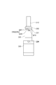
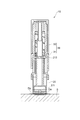
- FIG. 1 is a perspective view of the applicator 10 from below.
- FIG. 2 is a perspective view of the main body 20 from below.
- FIG. 3 is a front view of the main body 20.
- FIG. 4 is a right side view of the main body 20.
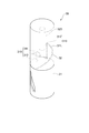
- FIG. 5 is a perspective view of the cap 30 from above.
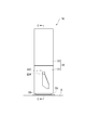
- FIG. 6 a front view, a plan view, and a bottom view of the applicator 10 are combined into one.
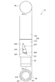
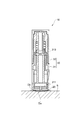
- FIG. 7 is a cross-sectional view taken along line AA of FIG. 6 (front view).
- the applicator 10 is a cylindrical auxiliary device used for applying microneedles to the skin.
- the applicator 10 includes a cylindrical main body 20 whose one end is in contact with the skin during use, and a cylindrical cap 30 attached to the main body 20 so as to cover the other end of the main body 20. I have.
- the main body 20 side is defined as the lower side of the applicator 10
- the cap 30 side is defined as the upper side of the applicator 10.
- the main body 20 has a columnar transmission member 210 for applying a biasing force of the spring 40 to the microneedle applied to the skin, and a cylindrical housing 220 that houses the transmission member 210 and guides the reciprocating movement of the transmission member 210. And.
- the transmission member 210 includes a transmission plate 211 that collides with the microneedles, and a cylindrical bar member 212 that extends in a direction orthogonal to the surface of the transmission plate 211.
- the transmission plate 211 includes a first plate portion 211a and a second plate portion 211b that face each other, and a columnar connecting portion 211c that connects these plate portions (see FIGS. 2 and 7).
- the 1st board part 211a and the 2nd board part 211b are disk shape.
- two stoppers 213 extending in a direction orthogonal to the axial direction of the rod-shaped member 212 (that is, the axial direction of the transmission member 210) are provided.
- the two stoppers 213 are realized by a single shaft member that penetrates the rod-shaped member 212 along the radial direction of the rod-shaped member 212, and therefore are present 180 degrees apart from each other on one orthogonal axis ( (See FIG. 4).
- a space (accommodating portion) 212a for accommodating the first plate portion 211a of the transmission plate 211 is formed at the lower end of the rod-shaped member 212 (see FIG. 7). As shown in FIG.
- the transmission plate 211 is not fixed to the rod-shaped member 212 but is provided at the lower end of the rod-shaped member 212 with play in the axial direction of the rod-shaped member 212. Therefore, the transmission plate 211 can move in the axial direction of the rod-shaped member 212.
- the movable range (play range) of the transmission plate 211 with respect to the rod-shaped member 212 is limited to a range in which the first plate portion 211a can move in the housing portion 212a.
- the transmission plate 211 since the transmission plate 211 is hooked on the rod-shaped member 212, when the rod-shaped member 212 moves upward, the transmission plate 211 also moves upward.
- the transmission member 210 is actuated by a spring 40 which will be described later, first, the rod-shaped member 212 collides with the second plate portion 211b of the transmission plate 211, and then the rod-shaped member 212 and the transmission plate 211 move together as a unit. Thereafter, the lower end (accommodating portion 212a) of the bar-like member 212 stops at a portion above the lower end 221 of the applicator 10, but the transmission plate 211 continues to drop due to inertial force and transmits the urging force of the spring 40 to the microneedle.
- the housing 220 covers a portion of the transmission member 210 from the transmission plate 211 to the stopper 213.
- the lower end 221 of the housing 220 is in contact with the skin when the applicator 10 is used, and the transmission plate 211 is located in the vicinity of the lower end 221.
- the housing 220 is formed in a two-stage nesting shape in which the lower stage 222 has a larger diameter than the upper stage 223.
- Two protrusions 224 are provided 180 degrees apart from each other at the upper end of the side surface of the lower stage 222 (see FIG. 4).
- the cross-sectional shape of the protrusion 224 is a circle.
- the upper end 225 of the housing 220 has two serrated convex portions 230.
- Each convex portion 230 includes an inclined portion (first inclined portion) 231 that is spirally inclined over a half circumference (a range of 180 degrees), and a wall that is cut off from the top of the inclined portion 231 along the axial direction of the housing 220. Part 232 (see FIG. 3).
- the inclined portion 231 rises as it proceeds counterclockwise (along one circumferential direction).
- the stopper 213 of the rod-like member 212 is placed on the upper end 225 of the housing 220. In a state where no external force is applied, each stopper 213 hits the wall portion 232 (see FIG. 3).
- An annular member 250 for placing the lower end 221 of the spring 40 is further placed on the upper end 225 of the housing 220 that houses the transmission member 210. Since the diameter of the annular member 250 is substantially the same as the diameter of the upper stage 223 of the housing 220, when the main body 20 is viewed from above, the tip of the stopper 213 is exposed (see FIG. 4).
- the cap 30 includes a cap body 31 formed in a two-stage nesting shape (see FIG. 7) having a larger diameter in the lower stage than in the upper stage, and a grip portion 32 that covers the cap body 31 so as to cover the upper stage. Become.
- the outer diameter of the grip portion 32 is matched with the lower outer diameter of the cap body 31.
- the cap body 31 is rotatable with respect to the grip portion 32.
- the upper inner wall of the cap body 31 is formed with two sawtooth-shaped stopper guiding portions 310 that come into contact with the stopper 213 when the cap 30 is pushed toward the body 20.
- Each stopper guiding portion 310 was cut off along the axial direction of the cap 30 from the inclined portion (second inclined portion) 311 that spirally inclined over a half circumference (a range of 180 degrees) and the top portion of the inclined portion 311.
- One stopper guiding portion 310 corresponds to one convex portion 230. Similar to the inclined portion 231 of the convex portion 230, the inclined portion 311 rises as it proceeds counterclockwise when the main body 20 is viewed from above.
- the gradient of the inclined portion 311 (gradient of the stopper guiding portion 310) is larger than the gradient of the inclined portion 231 (gradient of the convex portion 230).
- a cylindrical spring guide 320 extending along the axial direction of the cap body 31 is provided at the center of the upper wall of the cap body 31.
- two substantially trapezoidal openings 330 are formed on the lower side surface of the cap body 31 so as to correspond to the two protrusions 224 of the housing 220.
- the two openings 330 are 180 degrees apart from each other.
- a pair of opposite sides parallel to each other extends along the axial direction of the cap body 31 (cap 30), and another pair of opposite sides, that is, the upper side 333 and the lower side 334 are both.
- the outer wall of the cap main body 31 is inclined so as to rise as it advances clockwise (see also FIG. 1).
- the upper side 333 is inclined in a direction opposite to the inclined portions 231 and 331 (that is, in a direction opposite to the sliding direction of the stopper 213).
- the lowermost portion 331 of the opening 330 is chamfered so that the protrusion 224 is placed, and the uppermost portion 332 of the opening 330 is a cutout portion having a size enough to accommodate the protrusion 224.
- the spring 40 is an elastic member that imparts predetermined kinetic energy to the transmission member 210, and is a compression spring that accumulates energy during compression.
- the spring 40 is cylindrical, and as shown in FIG. 7, the upper end of the spring 40 is placed in the cap 30 (more specifically, in the cap body 31) so as to surround the spring guide portion 320. The lower end of the spring 40 is in contact with the annular member 250.
- the transverse elastic modulus As parameters relating to the energy of the transmission member 210 that is operated by the biasing force of the spring 40, the transverse elastic modulus, the wire diameter, the number of turns, the average coil diameter, the distance indicating how much the spring 40 is reduced from the natural length, and the speed And the mass of the spring and the mass of the transmission member.
- Modulus of transverse elasticity is determined by the material of the spring, for example, if the stainless 68500N / m 2, a 78500N / m 2 if piano wire (iron). Other parameters may be determined in consideration of a desired biasing force, the dimensions of the applicator 10, and the like.
- Equation (1) shows the relationship between the spring constant, the shape of the spring, and the material
- Equation (2) shows the relationship between the mass and size of the spring
- Equation (3) shows the relationship between spring energy and kinetic energy
- Equation (4) shows the relationship between spring speed, energy (E), and mass.
- G is a transverse elastic modulus (N / m 2 ), d is a wire diameter (m), n is the number of turns, D is an average coil diameter (m), k is a spring constant (N / m), x is Distance (m), v is speed (v / s), l is the length (m) of the spring when stretched, ⁇ is the density (kg / m 3 ), m is the mass of the spring (kg), M is the transmission member Mass (kg).
- the puncture performance of the applicator depends on the mass and speed of the transmission member. By changing the masses of the first plate portion 211a and the second plate portion 211b, the collision parameter can be changed without changing the applicator body.
- the dimensions of the applicator 10 may be determined according to the dimensions of the microneedle. For example, if the shape of the lower end 221 of the housing 220 is matched to the shape of the microneedle and the inner diameter of the lower end 221 is matched to the outer diameter of the microneedle, the size of the applicator 10 can be reduced according to the size of the microneedle. it can. Further, when the lower end 221 is molded in this way, the applicator 10 is not displaced in the radial direction (width direction) with respect to the microneedle when the applicator 10 is positioned on the microneedle.
- the urging force of the spring 40 can be transmitted to the microneedle via the transmission member 210 while maintaining the positional relationship parallel to the microneedle.
- puncture can be performed reliably (reproducibility of puncture increases).
- the method of determining a dimension is not limited to these.
- the material of the applicator is not limited, but a material having a strength capable of maintaining the biasing force of the spring 40 is desirable.
- a material having a strength capable of maintaining the biasing force of the spring 40 is desirable.
- synthetic or natural resin materials such as ABS resin, polystyrene, polypropylene, polyacetal (POM) resin, etc.
- polyacetal (POM) resin is most preferable in consideration of the slidability of the applicator.
- the transmission member 210 may be produced using the same material as the microneedle.
- FIG. 8 is a diagram showing an initial state when the applicator 10 is used.
- 9 is a cross-sectional view taken along the line BB of FIG.
- FIG. 10 is a view showing a state where the transmission member 210 is raised.
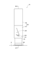
- FIG. 11 is a view showing a state of the applicator 10 when the transmission member 210 is operated.
- 12 is a cross-sectional view taken along the line CC of FIG.
- the initial state of the applicator 10 is as shown in FIGS.
- the cap 30 is raised to a position where the lowermost portion 331 of the opening 330 contacts the protrusion 224.
- the stopper 213 is in a state where it hits the wall portion 232 of the upper end 225 of the housing 220 (see FIGS. 2 to 4), and the transmission plate 211 is located at the lower end of the housing 220.
- the applicator 10 is positioned and held on the microneedle Da applied to the skin S, and the cap 30 is pushed toward the skin S while holding the grip portion 32.
- the microneedle Da may be affixed on the skin with the cover material Db (refer FIG. 9). Further, the microneedle can be built in the applicator 10 by holding the microneedle on the transmission plate 211.
- the spring 40 starts to contract, and the urging force starts to be stored in the spring 40. Further, the stopper guiding portion 310 inside the cap 30 moves downward, and the stopper 213 starts to slide on the inclined portion 231.
- the upper side 333 of the opening 330 comes into contact with the projection 224 and then moves downward while in contact with the projection 224, so that the cap main body 31 is seen from above the applicator 10.
- the stopper 213 sandwiched between the inclined portion 231 of the upper end 225 of the housing 220 and the inclined portion 311 of the stopper guiding portion 310 of the cap body 31 is pushed by the stopper guiding portion 310 of the rotating cap body 31. And slides upward along the inclined portion 231. Accordingly, the transmission member 210 moves upward while rotating.
- the cap 30 only the cap body 31 rotates, and the grip portion 32 held by the user does not rotate.
- the stopper 213 When the user further presses the cap 30 in such a state, the stopper 213 further rotates counterclockwise as viewed from above the applicator 10 and comes off the inclined portion 231. As a result, the transmission member 210 loses support and moves downward of the applicator 10 by the urging force of the spring 40 (the stopper 213 moves downward along the wall portion 232), and as shown in FIGS. Collides with the needle Da. By this collision, the needle portion of the microneedle Da perforates the stratum corneum of the skin, and the active ingredient applied to the microneedle Da is administered into the body through the needle portion. At this time, as shown in FIG. 11, since the projection 224 hits the uppermost portion 332 of the opening 330, the cap 30 does not fall any further. Further, since the stopper 213 is again placed on the upper end 225 of the housing 220 while being in contact with the wall portion 232, the transmission member 210 does not fall below the lower end 221 of the housing 220.
- the lower end (the accommodating portion 212a) of the rod-like member 212 stops at a portion above the lower end 221 of the applicator 10, but the transmission is performed.
- the plate 211 continues to fall due to inertial force.
- the transmission plate 211 transmits the urging force of the spring 40 to the microneedle. Therefore, strictly speaking, the transmission plate 211 transmits the biasing force of the spring 40 to the microneedle indirectly rather than directly.
- applicator 10 When the user stops pressing the cap 30 after using the applicator 10 as described above, the cap 30 is moved upward by the extension force of the spring 40 until the lowermost portion 331 of the opening 330 hits the protrusion 224. At this time, since the lower side 334 of the opening 330 is in contact with the protrusion 224, the lowermost part 331 is guided to the protrusion 224. As a result, the applicator 10 returns to the initial state shown in FIGS. Therefore, when the applicator 10 is used next time, the applicator 10 returned to the initial state may be positioned and held on another microneedle and the cap 30 may be pushed toward the skin. Accordingly, applicator 10 is a self-actuating applicator.
- the stopper 213 of the rod-like member 212 moves along the inclined portion 231 of the upper end 225 of the housing 220.
- the transmission member 210 moves away from the microneedle against the biasing force of the spring 40.
- the stopper 213 is detached from the inclined portion 231, so that the transmission member 210 transmits the urging force of the spring 40 to the microneedle.
- microneedle is applied to skin.
- the applicator 10 can also be referred to as a latch-less applicator.
- the transmission member 210 Since the transmission member 210 operates only when the stopper 213 is disengaged from the inclined portion 231, the urging force transmitted to the microneedle is constant regardless of who administers it. Therefore, puncture can be performed reliably (reproducibility of puncture is increased).
- the cap 30 while the cap 30 is pushed and the upper side 333 of the opening 330 is in contact with the protrusion 224, the cap 30 (more specifically, the cap body 31) is raised and the inclined portions 231 and 311 are raised. Rotate in the direction you want. And the force by this rotation acts on the inclination part 311 which presses the stopper 213. FIG. Therefore, the user can easily move the transmission member 210 upward with a small force. In this operation, only the cap main body 31 rotates and the grip portion 32 gripped by the user does not rotate, so that the arm does not twist while the user presses the cap 30. From this point, the applicator 10 is convenient for the user.
- the gradient of the inclined portion 311 is larger than the gradient of the inclined portion 231, the force by which the inclined portion 311 pushes the stopper 213 (the force acting in the direction along the inclined portion 231) increases. Therefore, the force generated when the user pushes the cap 30 is transmitted to the stopper 213 more efficiently. Therefore, the user can easily move the transmission member 210 upward with a small force.
- the applicator 10 has an advantage over the self-actuating applicator described in Patent Document 1 above in that it has only one spring in addition to the latchless feature. Specifically, since the self-actuating applicator described in Patent Document 1 requires two springs, ie, a pressing spring and a pre-setting spring, the applicator is inevitably large. On the other hand, since the applicator 10 only needs to prepare one spring 40 as an elastic member, the applicator 10 can be downsized accordingly.
- the shape of the opening 330 may be arbitrarily determined in consideration of design and the like on the assumption that a side having the same function as the upper side 333 is provided.
- the opening 330 is formed in the lower stage of the cap body 31, but a hole is not formed in a portion in contact with the protrusion 224, and a recess having the same or equivalent shape as the opening 330 is formed in the inner wall of the lower stage of the cap body 31. It may be formed. Also in this case, while the cap 30 is pushed and the upper side of the recess is in contact with the protrusion 224, the cap body 31 rotates in the direction in which the inclined portions 231 and 311 rise. And the force by this rotation acts on the inclination part 311 which presses the stopper 213. FIG. Therefore, the user can easily move the transmission member 210 upward with a small force. Moreover, since the edge does not appear on the outer surface of the cap when the concave portion is formed, it is possible to cope with a case where such a design is desired.
- the applicator 10 has a cylindrical shape, but the appearance of the applicator is not limited to this.
- the applicator has a polygonal cross section, the outer wall of the applicator is rounded as a whole, or the outer wall is recessed.
- a step may be provided.
- a fine groove may be formed on the surface of the outer wall or a coating may be applied.
- the cap 30 and the transmission member 210 may be provided with air holes for escaping air, thereby reducing the air resistance and reducing the weight.
- the two stoppers 213 are provided, and the two convex portions 230 and the two stopper guiding portions 310 are provided in accordance therewith, but the number of stoppers is not limited to this.
- only one stopper may be provided, and one convex portion and one stopper guide portion may be formed.
- the inclined portions on the housing side and the cap side are each formed over 360 degrees.
- four stoppers may be provided 90 degrees apart from each other, and four convex portions and four stopper guide portions may be formed.
- each inclined portion is formed over a range of 90 degrees on both the housing side and the cap side.
- three stoppers may be provided 120 degrees apart from each other, and three convex portions and three stopper guide portions may be formed. In this case, each inclined portion is formed over a range of 120 degrees on both the housing side and the cap side.
- the gradient of the inclined portions 231 and 311 in the above embodiment may be arbitrarily determined on the assumption that the gradient of the inclined portion 311 (cap 30 side) is greater than or equal to the gradient of the inclined portion 231 (housing 220 side).
- the slope of each inclined portion and the number of stoppers described above may be set in consideration of the operability of the applicator.
- the installation mode of the spring is not limited to that of the above embodiment.
- a columnar spring 41 may be inserted into the rod-shaped member 212.
- the lower end of the spring 41 is in contact with a shaft member for realizing the stopper 213, and the upper end of the spring 41 is in contact with the spring guide portion 320.
- the shape of the spring is not limited, and for example, a conical spring may be used. Thereby, since the length of the spring in the expansion / contraction direction at the time of compression can be suppressed, the size of the applicator in the axial direction can be suppressed and the applicator can be reduced in size and weight.
- the spring 40 is used, but an elastic member other than the spring may be used.
- the transmission plate 211 is attached to the rod-shaped member 212 with play, but the transmission plate 211 may be fixed to the rod-shaped member 212.
- the transmission plate 211 and the rod-shaped member 212 may be integrally formed.
- the caps 30 are designed so that the cap body 31 can rotate with respect to the grip part 32, but a cap in which the cap body and the grip part are integrated may be adopted.
- Opening, 333 Upper side of the opening (contacts the protrusion when the cap is pushed toward the transmission member) One side of the opening), 334... The lower side of the opening (the other side of the opening formed so as to return the pressed cap to the initial state).
Abstract
Priority Applications (5)
| Application Number | Priority Date | Filing Date | Title |
|---|---|---|---|
| KR1020137033374A KR101973824B1 (ko) | 2011-07-27 | 2012-07-13 | 어플리케이터 |
| US14/123,523 US9216252B2 (en) | 2011-07-27 | 2012-07-13 | Applicator |
| EP12818293.8A EP2737924B1 (fr) | 2011-07-27 | 2012-07-13 | Applicateur |
| JP2013525666A JP5627788B2 (ja) | 2011-07-27 | 2012-07-13 | アプリケータ |
| CN201280035439.7A CN103687643B (zh) | 2011-07-27 | 2012-07-13 | 施放器 |
Applications Claiming Priority (2)
| Application Number | Priority Date | Filing Date | Title |
|---|---|---|---|
| JP2011164723 | 2011-07-27 | ||
| JP2011-164723 | 2011-07-27 |
Publications (1)
| Publication Number | Publication Date |
|---|---|
| WO2013015136A1 true WO2013015136A1 (fr) | 2013-01-31 |
Family
ID=47600987
Family Applications (1)
| Application Number | Title | Priority Date | Filing Date |
|---|---|---|---|
| PCT/JP2012/067918 WO2013015136A1 (fr) | 2011-07-27 | 2012-07-13 | Applicateur |
Country Status (7)
| Country | Link |
|---|---|
| US (1) | US9216252B2 (fr) |
| EP (1) | EP2737924B1 (fr) |
| JP (1) | JP5627788B2 (fr) |
| KR (1) | KR101973824B1 (fr) |
| CN (1) | CN103687643B (fr) |
| TW (1) | TW201321037A (fr) |
| WO (1) | WO2013015136A1 (fr) |
Cited By (8)
| Publication number | Priority date | Publication date | Assignee | Title |
|---|---|---|---|---|
| WO2014193729A1 (fr) * | 2013-05-31 | 2014-12-04 | 3M Innovative Properties Company | Appareil d'injection à micro-aiguille comprenant un actionneur inversé |
| WO2017038499A1 (fr) * | 2015-09-02 | 2017-03-09 | 久光製薬株式会社 | Applicateur |
| JPWO2015068702A1 (ja) * | 2013-11-05 | 2017-03-09 | 久光製薬株式会社 | アプリケータ |
| US9872975B2 (en) | 2013-05-31 | 2018-01-23 | 3M Innovative Properties Company | Microneedle injection and infusion apparatus and method of using same |
| US9895520B2 (en) | 2013-05-31 | 2018-02-20 | 3M Innovative Properties Company | Microneedle injection apparatus comprising a dual cover |
| US9913970B2 (en) | 2012-12-21 | 2018-03-13 | Hisamitsu Pharmaceutical Co., Ltd. | Applicator |
| CN107921219A (zh) * | 2015-08-24 | 2018-04-17 | 阿达米制药公司 | 注射器装置 |
| JP2018102680A (ja) * | 2016-12-27 | 2018-07-05 | 久光製薬株式会社 | アプリケータおよび穿刺キット |
Families Citing this family (9)
| Publication number | Priority date | Publication date | Assignee | Title |
|---|---|---|---|---|
| CN104245041B (zh) * | 2012-04-05 | 2016-08-17 | 久光制药株式会社 | 穿刺装置及其制造方法 |
| CN106456869B (zh) * | 2014-04-03 | 2019-12-03 | 诺和诺德股份有限公司 | 针装置 |
| JP6695694B2 (ja) * | 2016-01-08 | 2020-05-20 | マクセルホールディングス株式会社 | 美容器具 |
| WO2018116990A1 (fr) * | 2016-12-20 | 2018-06-28 | 久光製薬株式会社 | Applicateur |
| EP3718595B1 (fr) | 2017-11-30 | 2023-09-13 | Hisamitsu Pharmaceutical Co., Inc. | Applicateur, cartouche et kit d'application |
| DE102019001251A1 (de) * | 2019-02-21 | 2020-08-27 | Lts Lohmann Therapie-Systeme Ag | Applikator für Mikronadelpflaster |
| KR102163200B1 (ko) * | 2020-07-09 | 2020-10-08 | 주식회사 씨에이치바이오 | 리필형 펌프 용기를 수용하는 화장품 용기 |
| WO2023250117A2 (fr) * | 2022-06-24 | 2023-12-28 | Vaxess Technologies, Inc. | Applicateur pour timbre de médicament |
| US20240075215A1 (en) * | 2022-09-07 | 2024-03-07 | Inocuject Corp. | Injector and Injection Method Therefor |
Citations (4)
| Publication number | Priority date | Publication date | Assignee | Title |
|---|---|---|---|---|
| JP2005533625A (ja) * | 2002-07-19 | 2005-11-10 | スリーエム イノベイティブ プロパティズ カンパニー | マイクロニードルデバイスおよびマイクロニードル送達装置 |
| JP2007509706A (ja) | 2003-10-31 | 2007-04-19 | アルザ・コーポレーシヨン | 微小突起列のための自己−作動性アプリケーター |
| JP2008534152A (ja) * | 2005-03-28 | 2008-08-28 | アルザ コーポレイション | 微小突起で皮膚を穿刺する装置及び方法 |
| JP2010540059A (ja) * | 2007-09-25 | 2010-12-24 | ベクトン・ディキンソン・フランス・エス.エー.エス. | 安全シールドによって非活動化することができる容器保持手段を備える自動注射装置 |
Family Cites Families (18)
| Publication number | Priority date | Publication date | Assignee | Title |
|---|---|---|---|---|
| US3756242A (en) * | 1972-01-04 | 1973-09-04 | Micro Motors Inc | Mechanical scarifier |
| USD322671S (en) | 1989-11-22 | 1991-12-24 | Becton, Dickinson And Company | Needle shield or the like |
| US8465468B1 (en) * | 2000-06-29 | 2013-06-18 | Becton, Dickinson And Company | Intradermal delivery of substances |
| USD447231S1 (en) | 2000-08-09 | 2001-08-28 | Syncor International Corporation | Radiopharmaceutical container |
| AU2001296827B2 (en) | 2000-10-13 | 2005-11-17 | Alza Corporation | Microblade array impact applicator |
| IL161709A0 (en) | 2001-11-30 | 2004-09-27 | Novo Nordisk As | A safety needle assembly |
| AU2003209645A1 (en) | 2002-03-04 | 2003-09-16 | Nano Pass Technologies Ltd. | Devices and methods for transporting fluid across a biological barrier |
| AU2003268205B2 (en) | 2002-08-29 | 2010-02-18 | Becton, Dickinson And Company | Microabrader with controlled abrasion features |
| WO2006052737A1 (fr) | 2004-11-04 | 2006-05-18 | Sid Technologies, Llc | Injecteur automatique |
| EP1919540B1 (fr) | 2005-09-01 | 2016-05-18 | Owen Mumford Limited | Ensemble de coiffe d aiguille |
| EP2043710B1 (fr) | 2006-07-15 | 2011-07-06 | Novo Nordisk A/S | Système d'administration médicale avec élément de blocage souple |
| FR2913201B1 (fr) | 2007-03-02 | 2009-11-20 | Becton Dickinson France | Protection pour couvrir l'extremite d'un dispositif d'administration ou d'un sous-ensemble,sous-ensemble et dispositif d'administration |
| GB0704351D0 (en) | 2007-03-07 | 2007-04-11 | Medical House Plc The | Improved autoinjector |
| USD612487S1 (en) | 2007-03-15 | 2010-03-23 | Bristol-Myers Squibb Co. | Injector |
| USD565732S1 (en) | 2007-04-23 | 2008-04-01 | West Pharmaceutical Services, Inc. | Needle shield |
| USD612493S1 (en) | 2008-12-02 | 2010-03-23 | Helvoet Pharma Belgium N.V. | Needle protecting device |
| USD627459S1 (en) | 2009-03-10 | 2010-11-16 | Nipro Corporation | Needle for medical purposes |
| USD655001S1 (en) | 2011-05-10 | 2012-02-28 | West Pharmaceutical Services Deutschland Gmbh & Co. Kg | Needle shield |
-
2012
- 2012-07-13 EP EP12818293.8A patent/EP2737924B1/fr active Active
- 2012-07-13 US US14/123,523 patent/US9216252B2/en active Active
- 2012-07-13 KR KR1020137033374A patent/KR101973824B1/ko active IP Right Grant
- 2012-07-13 WO PCT/JP2012/067918 patent/WO2013015136A1/fr active Application Filing
- 2012-07-13 JP JP2013525666A patent/JP5627788B2/ja active Active
- 2012-07-13 CN CN201280035439.7A patent/CN103687643B/zh active Active
- 2012-07-27 TW TW101127228A patent/TW201321037A/zh unknown
Patent Citations (4)
| Publication number | Priority date | Publication date | Assignee | Title |
|---|---|---|---|---|
| JP2005533625A (ja) * | 2002-07-19 | 2005-11-10 | スリーエム イノベイティブ プロパティズ カンパニー | マイクロニードルデバイスおよびマイクロニードル送達装置 |
| JP2007509706A (ja) | 2003-10-31 | 2007-04-19 | アルザ・コーポレーシヨン | 微小突起列のための自己−作動性アプリケーター |
| JP2008534152A (ja) * | 2005-03-28 | 2008-08-28 | アルザ コーポレイション | 微小突起で皮膚を穿刺する装置及び方法 |
| JP2010540059A (ja) * | 2007-09-25 | 2010-12-24 | ベクトン・ディキンソン・フランス・エス.エー.エス. | 安全シールドによって非活動化することができる容器保持手段を備える自動注射装置 |
Cited By (20)
| Publication number | Priority date | Publication date | Assignee | Title |
|---|---|---|---|---|
| US9913970B2 (en) | 2012-12-21 | 2018-03-13 | Hisamitsu Pharmaceutical Co., Ltd. | Applicator |
| US11771878B2 (en) | 2013-05-31 | 2023-10-03 | Kindeva Drug Delivery L.P. | Microneedle injection and infusion apparatus and method of using same |
| US9682222B2 (en) | 2013-05-31 | 2017-06-20 | 3M Innovative Properties Company | Microneedle injection apparatus comprising an inverted actuator |
| US9872975B2 (en) | 2013-05-31 | 2018-01-23 | 3M Innovative Properties Company | Microneedle injection and infusion apparatus and method of using same |
| US9895520B2 (en) | 2013-05-31 | 2018-02-20 | 3M Innovative Properties Company | Microneedle injection apparatus comprising a dual cover |
| US10716926B2 (en) | 2013-05-31 | 2020-07-21 | Kindeva Drug Delivery L.P. | Microneedle injection and infusion apparatus and method of using same |
| US10695547B2 (en) | 2013-05-31 | 2020-06-30 | 3M Innovative Properties Company | Microneedle injection apparatus comprising an inverted actuator |
| WO2014193729A1 (fr) * | 2013-05-31 | 2014-12-04 | 3M Innovative Properties Company | Appareil d'injection à micro-aiguille comprenant un actionneur inversé |
| US10391290B2 (en) | 2013-05-31 | 2019-08-27 | 3M Innovative Properties Company | Microneedle injection apparatus comprising a dual cover |
| US10086183B2 (en) | 2013-11-05 | 2018-10-02 | Hisamitsu Pharmaceutical Co., Inc. | Applicator |
| JPWO2015068702A1 (ja) * | 2013-11-05 | 2017-03-09 | 久光製薬株式会社 | アプリケータ |
| CN107921219A (zh) * | 2015-08-24 | 2018-04-17 | 阿达米制药公司 | 注射器装置 |
| CN108136165A (zh) * | 2015-09-02 | 2018-06-08 | 久光制药株式会社 | 施放器 |
| JPWO2017038499A1 (ja) * | 2015-09-02 | 2018-05-31 | 久光製薬株式会社 | アプリケータ |
| KR102135518B1 (ko) * | 2015-09-02 | 2020-07-17 | 히사미쓰 세이야꾸 가부시키가이샤 | 어플리케이터 |
| KR20180043309A (ko) * | 2015-09-02 | 2018-04-27 | 히사미쓰 세이야꾸 가부시키가이샤 | 어플리케이터 |
| CN108136165B (zh) * | 2015-09-02 | 2020-11-06 | 久光制药株式会社 | 施放器 |
| US10828480B2 (en) | 2015-09-02 | 2020-11-10 | Hisamitsu Pharmaceutical Co., Inc. | Applicator |
| WO2017038499A1 (fr) * | 2015-09-02 | 2017-03-09 | 久光製薬株式会社 | Applicateur |
| JP2018102680A (ja) * | 2016-12-27 | 2018-07-05 | 久光製薬株式会社 | アプリケータおよび穿刺キット |
Also Published As
| Publication number | Publication date |
|---|---|
| CN103687643B (zh) | 2016-04-20 |
| US20140128818A1 (en) | 2014-05-08 |
| TW201321037A (zh) | 2013-06-01 |
| KR101973824B1 (ko) | 2019-04-29 |
| EP2737924B1 (fr) | 2019-03-27 |
| KR20140039228A (ko) | 2014-04-01 |
| EP2737924A1 (fr) | 2014-06-04 |
| JP5627788B2 (ja) | 2014-11-19 |
| EP2737924A4 (fr) | 2015-05-27 |
| TWI561262B (fr) | 2016-12-11 |
| CN103687643A (zh) | 2014-03-26 |
| JPWO2013015136A1 (ja) | 2015-02-23 |
| US9216252B2 (en) | 2015-12-22 |
Similar Documents
| Publication | Publication Date | Title |
|---|---|---|
| JP5627788B2 (ja) | アプリケータ | |
| JP5885667B2 (ja) | アプリケータ | |
| EP1695668B1 (fr) | Agrafeuse chirurgicale produisant un bruit ou une sensation d'impact lorsque la déformation de l'agrafe est terminée | |
| US8308747B2 (en) | Puncture device | |
| JP6265740B2 (ja) | アプリケータ | |
| WO2004103178A1 (fr) | Dispositif d'insertion d'aiguille | |
| US7988703B2 (en) | Patient's skin puncturing device | |
| EP2649938A1 (fr) | Instrument de ponction | |
| KR20180103998A (ko) | 자동 피드백 메카니즘, 및 사용자 피드백 능력을 갖는 약물 전달 장치 | |
| EP2823762B1 (fr) | Actionneur de piquage | |
| TW201113122A (en) | Structure of turning knob of ratchet wrench | |
| JP7351741B2 (ja) | 化粧料繰出容器 | |
| US20060205541A1 (en) | Table-tennis net assembly with a winder | |
| JP2007325677A (ja) | ハンドル付水筒 | |
| JP2018514320A (ja) | 組み立てを簡単にするための解放組み立てユニットを有する使い捨ての注射器 |
Legal Events
| Date | Code | Title | Description |
|---|---|---|---|
| WWE | Wipo information: entry into national phase |
Ref document number: 201280035439.7 Country of ref document: CN |
|
| 121 | Ep: the epo has been informed by wipo that ep was designated in this application |
Ref document number: 12818293 Country of ref document: EP Kind code of ref document: A1 |
|
| ENP | Entry into the national phase |
Ref document number: 2013525666 Country of ref document: JP Kind code of ref document: A |
|
| WWE | Wipo information: entry into national phase |
Ref document number: 2012818293 Country of ref document: EP |
|
| WWE | Wipo information: entry into national phase |
Ref document number: 14123523 Country of ref document: US |
|
| ENP | Entry into the national phase |
Ref document number: 20137033374 Country of ref document: KR Kind code of ref document: A |
|
| NENP | Non-entry into the national phase |
Ref country code: DE |