WO2013008572A1 - 通信装置、通信制御方法 - Google Patents
通信装置、通信制御方法 Download PDFInfo
- Publication number
- WO2013008572A1 WO2013008572A1 PCT/JP2012/064917 JP2012064917W WO2013008572A1 WO 2013008572 A1 WO2013008572 A1 WO 2013008572A1 JP 2012064917 W JP2012064917 W JP 2012064917W WO 2013008572 A1 WO2013008572 A1 WO 2013008572A1
- Authority
- WO
- WIPO (PCT)
- Prior art keywords
- acceleration
- communication
- wireless communication
- short
- communication device
- Prior art date
Links
- 238000004891 communication Methods 0.000 title claims abstract description 395
- 238000000034 method Methods 0.000 title claims description 37
- 230000001133 acceleration Effects 0.000 claims abstract description 195
- 238000001514 detection method Methods 0.000 claims description 44
- 230000033001 locomotion Effects 0.000 claims description 18
- 230000004044 response Effects 0.000 claims description 8
- 101100223811 Caenorhabditis elegans dsc-1 gene Proteins 0.000 description 88
- 238000012545 processing Methods 0.000 description 32
- 230000008569 process Effects 0.000 description 23
- 238000003384 imaging method Methods 0.000 description 13
- 238000009434 installation Methods 0.000 description 13
- 238000005259 measurement Methods 0.000 description 12
- 102100021202 Desmocollin-1 Human genes 0.000 description 10
- 101000968043 Homo sapiens Desmocollin-1 Proteins 0.000 description 10
- 101000880960 Homo sapiens Desmocollin-3 Proteins 0.000 description 10
- 238000003860 storage Methods 0.000 description 7
- 230000006870 function Effects 0.000 description 6
- 230000005540 biological transmission Effects 0.000 description 5
- 230000000694 effects Effects 0.000 description 5
- 238000012544 monitoring process Methods 0.000 description 5
- 238000005516 engineering process Methods 0.000 description 4
- 238000012546 transfer Methods 0.000 description 4
- 238000010586 diagram Methods 0.000 description 3
- 230000010365 information processing Effects 0.000 description 3
- 230000007246 mechanism Effects 0.000 description 3
- 230000004048 modification Effects 0.000 description 3
- 238000012986 modification Methods 0.000 description 3
- 230000008859 change Effects 0.000 description 2
- 238000005401 electroluminescence Methods 0.000 description 2
- 238000004519 manufacturing process Methods 0.000 description 2
- 230000009471 action Effects 0.000 description 1
- 230000004913 activation Effects 0.000 description 1
- 238000013459 approach Methods 0.000 description 1
- 230000008901 benefit Effects 0.000 description 1
- 238000006243 chemical reaction Methods 0.000 description 1
- 230000000295 complement effect Effects 0.000 description 1
- 230000006835 compression Effects 0.000 description 1
- 238000007906 compression Methods 0.000 description 1
- 230000001771 impaired effect Effects 0.000 description 1
- 239000004973 liquid crystal related substance Substances 0.000 description 1
- 229910044991 metal oxide Inorganic materials 0.000 description 1
- 150000004706 metal oxides Chemical class 0.000 description 1
- 238000002360 preparation method Methods 0.000 description 1
- 230000002265 prevention Effects 0.000 description 1
- 230000009467 reduction Effects 0.000 description 1
- 239000004065 semiconductor Substances 0.000 description 1
- 238000004904 shortening Methods 0.000 description 1
Images


Classifications
-
- H—ELECTRICITY
- H04—ELECTRIC COMMUNICATION TECHNIQUE
- H04W—WIRELESS COMMUNICATION NETWORKS
- H04W8/00—Network data management
- H04W8/005—Discovery of network devices, e.g. terminals
-
- H—ELECTRICITY
- H04—ELECTRIC COMMUNICATION TECHNIQUE
- H04W—WIRELESS COMMUNICATION NETWORKS
- H04W88/00—Devices specially adapted for wireless communication networks, e.g. terminals, base stations or access point devices
- H04W88/02—Terminal devices
-
- H—ELECTRICITY
- H04—ELECTRIC COMMUNICATION TECHNIQUE
- H04W—WIRELESS COMMUNICATION NETWORKS
- H04W4/00—Services specially adapted for wireless communication networks; Facilities therefor
- H04W4/80—Services using short range communication, e.g. near-field communication [NFC], radio-frequency identification [RFID] or low energy communication
-
- H—ELECTRICITY
- H04—ELECTRIC COMMUNICATION TECHNIQUE
- H04W—WIRELESS COMMUNICATION NETWORKS
- H04W52/00—Power management, e.g. Transmission Power Control [TPC] or power classes
- H04W52/02—Power saving arrangements
-
- H—ELECTRICITY
- H04—ELECTRIC COMMUNICATION TECHNIQUE
- H04W—WIRELESS COMMUNICATION NETWORKS
- H04W52/00—Power management, e.g. Transmission Power Control [TPC] or power classes
- H04W52/02—Power saving arrangements
- H04W52/0209—Power saving arrangements in terminal devices
- H04W52/0251—Power saving arrangements in terminal devices using monitoring of local events, e.g. events related to user activity
- H04W52/0254—Power saving arrangements in terminal devices using monitoring of local events, e.g. events related to user activity detecting a user operation or a tactile contact or a motion of the device
-
- Y—GENERAL TAGGING OF NEW TECHNOLOGICAL DEVELOPMENTS; GENERAL TAGGING OF CROSS-SECTIONAL TECHNOLOGIES SPANNING OVER SEVERAL SECTIONS OF THE IPC; TECHNICAL SUBJECTS COVERED BY FORMER USPC CROSS-REFERENCE ART COLLECTIONS [XRACs] AND DIGESTS
- Y02—TECHNOLOGIES OR APPLICATIONS FOR MITIGATION OR ADAPTATION AGAINST CLIMATE CHANGE
- Y02D—CLIMATE CHANGE MITIGATION TECHNOLOGIES IN INFORMATION AND COMMUNICATION TECHNOLOGIES [ICT], I.E. INFORMATION AND COMMUNICATION TECHNOLOGIES AIMING AT THE REDUCTION OF THEIR OWN ENERGY USE
- Y02D30/00—Reducing energy consumption in communication networks
- Y02D30/70—Reducing energy consumption in communication networks in wireless communication networks
Definitions
- the present disclosure relates to a communication device that performs short-range wireless communication and a communication control method thereof.
- short-range wireless communication technologies such as Bluetooth and TransferJet are known.
- Patent Document 1 describes a transfer jet as an example of short-range wireless communication.
- the radio wave for detecting the communication partner device is called a polling signal
- one device that performs communication transmits a polling signal, and an operation of returning a response signal from the other device according to the polling signal is performed.
- This polling is performed to determine the preparation status of each other and to synchronize the processing when starting transmission / reception of data between the two communicating devices.
- the polling signal is intermittently transmitted at a predetermined polling period.
- a radio signal (referred to as “standby radio wave” in this specification) is periodically transmitted to detect a communication partner. This is intended to automatically detect the communication partner by bringing the communication device close to the communication partner and start communication, and realize an intuitive operational feeling unique to short-range wireless communication.
- this communication partner detection method has the following problems.
- the communication partner is automatically detected by bringing it close to the communication partner, and the convenience of the user is improved by starting the communication.
- communication is started against the user's intention. Since communication is started regardless of the user's intention, data is unintentionally leaked or power consumption is increased.
- Patent Document 2 describes a system in which an acceleration detection unit is provided in a wireless communication device and the communication unit is controlled to operate when acceleration due to a user's operation is detected. Specifically, the communication processing is operated when acceleration due to the user's walking or the like is detected by an acceleration detecting means (for example, an acceleration sensor), and the communication processing is stopped when no acceleration is detected.
- an acceleration detecting means for example, an acceleration sensor
- communication processing is started and stopped by looking at the response of the acceleration sensor due to the user's action, so even if the user does not intend to start communication, the wireless communication device detects acceleration Will try to start communication. For example, it is considered that communication is started even when the user is carrying a wireless communication device. As a result, unintended communication may start or unnecessary power consumption may occur.
- Patent Document 3 a function for performing communication between communication devices using acceleration detection means in wireless communication devices as a trigger for detection of a predetermined vibration motion applied to adjacent wireless communication devices.
- the method of making it call is described. Specifically, it is necessary to first perform a two-step operation in which wireless communication devices are brought close to each other and further vibrated at a predetermined cycle as users shake hands. A predetermined vibration operation is detected and communication is started.
- the user starts communication two types of operations are required, and the latter operation is obviously a specific operation specialized for communication equipment. It becomes operation in. That is, the convenience of starting communication only by approaching is impaired.
- the present disclosure aims to prevent unnecessary communication from being performed and reduce the power required for connection standby while maintaining user convenience in a device that performs short-range wireless communication.
- the communication device is recognized by a short-range wireless communication unit that performs short-range wireless communication with an external communication device, an acceleration sensor that detects acceleration due to movement of the housing, and an acceleration detection signal from the acceleration sensor. From the measured acceleration fluctuation information, it is estimated whether or not the casing is in close proximity to the external communication device, the communication opportunity determination using the estimation result is performed, and when the communication opportunity is determined, the short-range wireless communication unit The control unit controls the generation of the standby radio wave in a dense state and controls the generation of the standby radio wave by the short-range wireless communication unit to a rough state or a stopped state except when the communication opportunity is determined. Prepare.
- control unit controls the short-range wireless communication unit to generate a standby radio wave in a dense state based on the determination of the communication opportunity, a predetermined time elapses without establishment of communication with the external communication device.
- the generation of the standby radio wave by the short-range wireless communication unit is controlled to the rough state or the stopped state.
- the communication control method of the present disclosure is a communication control method for a communication apparatus including a short-range wireless communication unit that performs short-range wireless communication with an external communication device and an acceleration sensor that detects acceleration due to movement of a housing. Then, from the acceleration fluctuation information recognized by the acceleration detection signal from the acceleration sensor, it is estimated whether or not the casing is brought close to the external communication device, and the communication opportunity is determined using the estimation result. If determined, the standby radio waves are generated from the short-range wireless communication unit in a dense state, and the generation of the standby radio waves by the short-range wireless communication unit is in a rough state or a stopped state, except when determined as the communication opportunity. Communication control method.
- the proximity state is determined based on the acceleration fluctuation observed when the user performs an operation of bringing the communication device casing close to the external communication device of the communication partner.
- the standby radio wave is kept in a rough state or stopped during normal times, thereby avoiding the generation of useless standby radio waves. Note that the standby radio wave is kept in a dense state only for a predetermined time, so that even if it is not in a proximity state with an external communication device, the dense state can be stopped early and power consumption can be reduced.
- a communication device that performs short-range wireless communication
- a situation in which communication connection is established is suppressed, and power required for connection standby is reduced. it can.
- the user's convenience can be maintained because there is no particular burden on the user.
- DSC digital still camera
- Configuration of DSC Digital Still Camera
- Communication control process of first embodiment ⁇ 3.
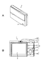
- FIG. 1A is a perspective view showing the appearance of the front side of the DSC 1 of the embodiment
- FIG. 1B is a rear view showing the appearance of the back side (operation surface side) of the DSC 1.
- the DSC 1 has a short-range wireless communication antenna 2 at the lower part of the front, for example.
- the DSC 1 includes the short-range wireless communication antenna 2, but a communication module including the short-range wireless communication antenna 2 (a module including a short-range wireless communication controller 10 and a storage area for communication described later) is the DSC 1. It may be removable.
- the DSC 1 has a display unit 3 by a display device such as an LCD (Liquid Crystal Display) or an organic EL (Electro-Luminescence) display on the back.
- a display device such as an LCD (Liquid Crystal Display) or an organic EL (Electro-Luminescence) display on the back.
- Each unit has an operator as the operation input unit 4.
- a playback menu activation button 41, a determination button 42, a cross key 43, a cancel button 44, a zoom key 45, a slide key 46, a shutter button 47, and the like are provided.
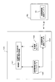
- FIG. 2 is a block diagram showing an internal configuration of the DSC 1 and a state of connection using short-range radio with another electronic device (wireless communication device 50).
- the DSC 1 and the external wireless communication device 5 can connect and communicate with each other using short-range wireless communication. Examples of short-range wireless communication include Bluetooth and transfer jet, but short-range wireless communication other than these may be used.
- the DSC 1 includes an imaging unit 5, an imaging signal processing unit 6, a CPU (Central Processing Unit) 7, a main memory 8, and a storage area in addition to the short-range wireless communication antenna 2, the display unit 3, and the operation input unit 4 shown in FIG. 9.
- Each unit internally transmits and receives control signals, captured image data, and the like to each other via the system bus 14.
- the short-range wireless communication antenna 2, the storage area 9, and the short-range wireless communication controller 10 are not provided in the DSC 1, but may be combined as a detachable module.
- the imaging unit 5 receives an object light and converts it into an electric signal, a lens system for condensing light from the object on the image sensor, a driving mechanism for moving the lens to perform focusing and zooming, It has a diaphragm mechanism. These drive mechanisms in the imaging unit 5 are driven in accordance with control signals from the CPU 7 which is the overall control unit.
- the image sensor is, for example, an image sensor such as a CCD (Charge Coupled Device) type or a CMOS (Complementary Metal Oxide Semiconductor) type.
- the imaging signal processing unit 6 performs A / D conversion, ISO gain adjustment, and other various signal processing on the electrical signal obtained by the imaging device of the imaging unit 5 to generate a captured image signal. Further, the imaging signal processing unit 6 performs processing such as compression processing on the captured image signal to form an image file as a still image or a moving image, or transfer to the display unit 3 as a through image displayed on the display unit 3.
- the display unit 3 In response to a control signal from the CPU 7, the display unit 3, for example, an image of a subject before imaging (through image), a content such as a captured still image file or moving image file, and an operation menu (GUI: Graphical User) Interface) etc. are displayed.
- GUI Graphical User
- the operation input unit 4 functions as input means for inputting a user operation, and sends a signal corresponding to the input operation to the CPU 7 or the like.
- various operators are shown as the operation input unit 4, but a touch panel integrated with the display unit 3 may be provided as the operation input unit 4.
- the main memory 8 is composed of, for example, a volatile memory such as a RAM (Random Access Memory), and temporarily stores data, programs, and the like as work areas when the CPU 7 processes various data. For example, the image data processed by the imaging signal processing unit at the timing when the shutter button 47 is pressed is once read into the main memory 8 and then written into the storage area 9.
- a volatile memory such as a RAM (Random Access Memory)
- RAM Random Access Memory
- the flash memory 11 stores an OS (Operating System) for the CPU 7 to control each unit, content files such as image files, and applications necessary for communication using short-range wireless communication. .
- OS Operating System
- the recording area 9 includes, for example, a non-volatile memory and functions as a storage unit that stores content files such as image files, attribute information of the image files, thumbnail images, and the like.
- the image file is stored in a format such as JPEG (Joint Photographic Experts Group), TIFF (Tagged Image File Format), or GIF (Graphics Interchange Format).
- the recording area medium 9 may be in the form of a memory card that can be attached to and detached from the DSC 1 or may be in the form of being built in the DSC 1.
- the recording area medium 9 is realized as a portable flash memory or a HDD (Hard Disk Drive).
- the short-range wireless communication antenna 2 receives a radio wave emitted from another electronic device or the like and converts it into a signal. Also, radio wave transmission is performed for standby radio waves and data transmission to other electronic devices.
- the short-range wireless communication controller 10 controls the transmission and reception of signals based on the short-range wireless communication connection protocol by the short-range wireless communication antenna 2 in cooperation with the CPU 7.
- the acceleration sensor 20 can detect the acceleration amount and acceleration direction of the housing due to the physical movement of the DSC 1 and convert it into a detection signal.
- the CPU 7 can read the value of the detection signal. It is assumed that the value of the detection signal can be used for various purposes.
- the CPU 7 performs overall control of the entire DSC 1 by executing a program stored in the flash memory 11 or the like, for example.
- the CPU 7 controls the operation of each necessary unit with respect to an imaging operation in accordance with a user operation, a playback operation of the captured image file, and a short-distance wireless communication operation with an external device.
- the system bus 14 connects the blocks such as the CPU 7 to each other, and enables transmission and reception of signals between the respective blocks.
- the audio output unit 11 is shown in the DSC 1. This is provided in the third and fourth embodiments, which will be described later, when voice notification (electronic sound or message voice output) is made to the user.
- the voice output unit 11 outputs a message voice or an electronic sound based on the control of the CPU 7.
- the notification to the user can also be executed as a message display on the display unit 3.
- the audio output unit 11 may not be provided.
- the wireless communication device 50 that performs short-range wireless communication with the DSC 1 can perform information processing (not shown) such as a short-range wireless communication antenna 51 and a CPU, ROM, RAM, display unit, operation input unit, and the like. It has a component. A signal received by the wireless communication device 5 is converted via the short-range wireless communication antenna 51 and the like, and arithmetic processing and the like by the CPU are performed. As a result, the wireless communication device 50 is connected to the DSC 1 in a standby state, which will be described later, by short-range wireless communication and can establish communication. In a state where communication is established, the DSC 1 can transmit a content file or the like included in the DSC 1 to the wireless communication device 5.
- information processing not shown
- a signal received by the wireless communication device 5 is converted via the short-range wireless communication antenna 51 and the like, and arithmetic
- FIG. 3 schematically shows the DSC 1 and the wireless communication device 50.
- the wireless communication device 50 is a device in which the DSC 1 can be placed on the upper side, and short-range wireless communication between the DSC 1 and the wireless communication device 50 is executed in a state where the DSC 1 is placed.
- the arrangement position of the short-range wireless communication antenna 2 in the housing is indicated as an antenna position 2P
- the arrangement position of the short-range wireless communication antenna 51 in the wireless communication device 50 is indicated as an antenna position 51P.
- devices need to be close to each other, but more specifically, antennas need to be close to each other.
- the wireless communication device 50 shown in FIG. 3 is connected to, for example, a personal computer, an image editing device, an image storage device, other information processing devices, an image processing device, and the like, and content files transmitted from the DSC 1 are transmitted to them. It can be transferred to other devices.
- the wireless communication device 50 may be a tablet personal computer or the like, which itself may be a transfer destination of a content file or the like.
- the DSC 1 When the user causes the DSC 1 to communicate with the wireless communication device 50 of the communication partner, the DSC 1 is placed on the wireless communication device 5 and close to the wireless communication device 5 as shown in FIG.
- the DSC 1 In short-distance wireless communication, since communication cannot be maintained unless communication devices are close to each other, it is unlikely that the user will continue to hold DSC 1 and communication is started by placing the device on the wireless communication device 50 as shown. It is common to be used.
- an operation in which the DSC 1 held by the user is placed on the wireless communication device 50 for communication is referred to as a “proximity operation”.
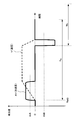
- the detection signal waveform from the acceleration sensor 20 in the DSC 1 shows a specific shape as shown in FIG. In FIG. 4, it is assumed that the user starts a proximity operation from the time axis TM0, and a speed change V and an acceleration change AV in that case are shown.
- the speed increases because the movement starts from the state where the DSC 1 is stopped, and thus a positive value is detected as the acceleration. Thereafter, if the speed is constant during the movement of the housing toward the wireless communication device 50, the acceleration shows a value of approximately zero, but when the DSC 1 is placed on the wireless communication device 5, the speed suddenly becomes zero. Therefore, a negative acceleration value is detected. That is, when the user performs a proximity operation, the acceleration sensor 20 of the DSC 1 detects the acceleration value as shown in FIG. 4, and therefore the CPU 7 of the DSC 1 uses the acceleration fluctuation information that can be observed as the detection signal waveform to calculate the DSC 1 It is possible to know that the housing of the vehicle has been operated in proximity.
- the DSC 1 normally sets standby radio waves to be in a rough state or a stopped state.
- the normal time is a period in which the DSC 1 is in a power-on state but is not particularly determined to perform near field communication.
- the DSC 1 determines that a proximity operation has been performed on the wireless communication device 50, the DSC 1 generates a standby radio wave in short-range wireless communication for a certain period of time in a dense state. After that, when a certain period of time has passed without communication being established, the standby radio wave is set to a sparse state or a stopped state.
- making a standby radio wave into a rough state means extending a cycle interval (polling cycle) for transmitting the standby radio wave.
- FIG. 6A shows an example of a polling cycle for generating a standby radio wave.
- the dense state means a case where the polling cycle P is short
- the rough state means a case where the polling cycle P is long. In the dense state, it is easy to detect the communication partner.
- the rough state is a state where it is difficult to detect the communication partner, but the detection is not completely stopped.
- the stopped state is a state in which the generation of standby radio waves is completely stopped. In this case, the communication partner is not detected.
- the operation of the embodiment may be either in a rough state or a stop state in the generation of standby radio waves during normal times or the like, and should be set according to the characteristics and personality of the device on which the function is installed. Is. Also, the specific polling period P values in the dense state and the coarse state should be set according to the characteristics and personality of the device.
- the dense state and the rough state described below indicate a state in which the polling period P is shortened and a state in which the polling period P is lengthened as the DSC 1 of this example, and a specific value of the period is not limited.
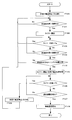
- FIG. 5 A specific processing example in which the DSC 1 determines acceleration fluctuation caused by the proximity operation and controls the standby radio wave will be described with reference to the flowchart shown in FIG. Note that the flowchart shown in FIG. 5 is described as a control process of the CPU 7 based on a program executed by the CPU 7, but the same process may be performed by hardware or performed by both hardware and software. Also good.
- the CPU 7 controls a normal standby radio wave as step F100. That is, the CPU 7 instructs the short-range wireless communication controller 10 to stop or generate a standby radio wave. In response to this, the short-range wireless communication controller 10 sets the standby radio wave to a stopped state or a rough state.
- step F101 the CPU 7 acquires an acceleration detection signal (acceleration measurement value) from the acceleration sensor 20, and monitors whether the acceleration value is equal to or greater than a certain threshold thA.
- FIG. 4 shows an example of the threshold thA and a threshold thB described later.
- the method of acquiring the detection value of the acceleration sensor 20 may be a mode in which the value of the acceleration sensor 20 is acquired from the CPU 7 at regular intervals, or a method of notifying the value from the acceleration sensor 20 by interruption or the like. When the acceleration measurement value does not exceed the threshold thA, the same monitoring is continued.
- step F101 when the acceleration measurement value exceeds the threshold thA, the CPU 7 proceeds to step F102.
- the CPU 7 starts time counting with the timer value Ta as a limit.
- the timer may be included in the CPU 7 as a function, or may be realized as a block other than the CPU 7, either of which may be used.
- the CPU 7 After starting the time count, the CPU 7 continues to acquire the acceleration measurement value of the acceleration sensor 20 and continues the monitoring processing of steps F103 and F104.
- step F103 it is monitored whether the time count has reached the timer value Ta.
- Step F104 it is monitored whether or not a value equal to or smaller than a certain threshold thB is obtained as an acceleration measurement value.
- the CPU 7 returns from the step F103 to the monitoring process of F101. If the CPU 7 detects that the acceleration measurement value is equal to or less than the threshold value B in step F104, the CPU 7 estimates that the proximity operation has been performed at this point, and determines that this is a communication opportunity.
- Steps F101 to F104 so far are performed when the acceleration in the positive direction according to the increase in the movement speed of the housing and the negative acceleration leading to the stop of the movement of the housing occur within a predetermined time (Ta). It is determined that the casing of the DSC 1 comes close to the wireless communication device 50 and has reached a communication opportunity. That is, within a predetermined time (timer value Ta) shown in FIG. 4, a positive acceleration measurement value corresponding to an increase in speed at the start of the proximity operation is detected, and the DSC 1 is placed on the wireless communication device 5 and rapidly. When the negative acceleration measurement value when the speed becomes zero is detected, the waveform shape shown in FIG. 4 is determined, and the proximity operation is estimated. On the other hand, even if a positive acceleration is detected, if no negative acceleration is detected until the timer value Ta is reached, the movement of the casing of the DSC 1 at that time is not a proximity operation, and the step Return to F101.
- the CPU 7 When it is determined that the operation is a proximity operation and the process proceeds to step F105, the CPU 7 starts a new time count with the timer value Tb as a limit. Further, the CPU 7 instructs the short-range wireless communication controller 10 to generate standby radio waves in the dense state. In response to this, the short-range wireless communication controller 10 performs an operation of generating a standby radio wave by shortening the polling cycle from the short-range wireless communication antenna 2. In this state, the short-range wireless communication controller 10 tries communication connection with the counterpart wireless communication device 50.
- step F106 the CPU 7 monitors whether the time count has reached the timer value Tb.
- step F107 it is monitored whether or not a communication partner device is detected. That is, the timer value Tb defines the upper limit time of the communication destination detection period while emitting standby radio waves in a dense state.
- the CPU 7 detects the communication partner device in step F107, the CPU 7 proceeds to step F108 and controls the short-range wireless communication controller 10 to start wireless communication.
- the CPU 7 proceeds to step F109 from step F106, and instructs the short-range wireless communication controller 10 to indicate the stop state or the rough state for the generation of the standby radio wave. To do.
- the short-range wireless communication controller 10 sets the standby radio wave to a stopped state or a rough state. Then, the CPU 7 returns to the monitoring process in step F101.
- the processing of FIG. 5 described above has the following characteristics.
- the CPU 7 controls the standby radio wave to a rough state or a stopped state during normal times.
- the CPU 7 estimates whether or not a proximity operation has been performed in which the casing of the DSC 1 is brought close to the wireless communication device 50 or the like from the acceleration fluctuation recognized by the acceleration detection signal (acceleration measurement value) from the acceleration sensor 20. If it is determined that the operation is a proximity operation, the communication opportunity is determined. -If it determines with a communication opportunity, CPU7 will control a standby radio wave to a dense state.
- the standby radio wave is set in a dense state only for a predetermined time (timer value Tb). If communication cannot be established during that period, the standby radio wave is returned to a normal state in which the standby radio wave is in a rough state or a stopped state.
- the polling cycle P has been described with reference to FIG. 6A, it is easy to detect the communication partner in the dense state, but it is difficult to detect the communication partner in the coarse state. In the stop state, the communication partner is not detected.
- the relationship between the power consumption and the polling cycle is shown in FIG. 6B. As the polling cycle P becomes shorter, the power consumption related to standby increases. In the rough state, the power consumption is small, and in the stopped state, there is no power consumption related to the standby radio wave.
- the standby radio wave is set in a dense state, and the rest is set in a rough state or a stopped state. Only when there is a high possibility that short-range wireless communication is intended, the possibility of communication connection can be increased. In other words, when the possibility that the user intends short-range wireless communication is low, the possibility that a communication connection is made can be reduced, which is preferable in terms of preventing a situation where unintended communication is performed as much as possible. It becomes. Furthermore, only when there is a high possibility that the user intends to use short-range wireless communication, a dense state with high power consumption is set. Otherwise, a rough state with low power consumption or a stop state without power consumption related to standby radio waves is set. Thus, it is effective in reducing power consumption related to standby.
- the proximity operation of the user is determined from the acceleration measurement value, the proximity operation is not necessarily “an operation in which the DSC 1 is placed on the wireless communication device 50”.
- an operation in which the user places the DSC 1 on a desk or the like is performed many times in normal use.
- the power is turned off, and in this case, the processing of FIG. 5 is not performed.
- the user may place the DSC 1 on the desk or the like with the power on.
- the waiting time of the timer value Tb is limited for generating a standby radio wave in a dense state without being able to detect the communication partner, the communication partner cannot be detected simply by being placed on the desk. Is not left in a dense state indefinitely, and returns to a rough state or a stopped state after a certain time. In other words, in this example, it is determined that there is a high possibility that the user intended short-range wireless communication, and the standby radio wave is set in a dense state. The state is not kept, and the state is returned to the rough state or the stopped state. As a result, even if the user's communication intention cannot be completely determined from the acceleration detection, the power consumption can be minimized.
- the standby radio wave is set to the rough state or the stop state may be determined according to the device, but the following effects are obtained.
- the power consumption reduction is more disadvantageous than in the stop state.
- the user may have a communication intention. That is, when the user performs an operation to bring the DSC 1 closer to the wireless communication device 50 or the like, the CPU 7 may not be able to detect it.
- the DSC 1 and the corresponding wireless communication device 50 are devices in which such a usage mode can be considered, it is preferable that the DSC 1 and the corresponding wireless communication device 50 are normally left in a rough state and leave at least the possibility of establishing a communication connection.
- the normal state is advantageous in reducing power consumption. Further, by setting the stop state, the effect of preventing communication unintended by the user is enhanced. However, conversely, when communication is desired, a specific proximity operation is requested from the user. Therefore, when the DSC 1 and the corresponding wireless communication device 50 perform communication only by a specific proximity operation, it is preferable to be in a stopped state during normal times.
- the acceleration sensor 20 detects the acceleration value of the waveform shape shown in FIG. 4 and also detects the three-dimensional generation direction of the acceleration. Specifically, it is assumed that the acceleration sensor 20 can detect the acceleration amount in the three-dimensional direction by detecting the value as a vector amount instead of the acceleration value as a scalar amount.
- the acceleration detection direction at the moment of proximity is X-axis, Y-axis, Z-axis with the upper part of DSC 1 as the positive direction of the X-axis as shown in FIG. If the axial direction is determined, acceleration (acceleration detection direction DET) is detected in the negative direction of the X axis.
- acceleration acceleration detection direction DET
- FIG. 7 (and FIGS. 8, 9, and 11 described later), the arrow U indicates the upper surface side of the DSC 1 and the arrow B indicates the bottom surface side of the DSC 1.
- the position of the short-range wireless communication antenna 2 is arranged on the bottom surface side in the DSC casing as indicated by a position 2P.
- the direction of the acceleration at that time is detected at the same time to determine which direction the proximity operation has been performed. Therefore, it is possible to more accurately detect whether or not the user intends to start communication than the method of the first embodiment.
- the direction in which DSC 1 approaches the communication partner wireless communication device 50 is the negative direction in the X-axis direction of DSC 1. Since the short-range wireless communication antenna 2 of the DSC 1 exists on the bottom surface of the DSC 1, it is in close contact with the wireless communication antenna 51 (position 51 ⁇ / b> P) of the wireless communication device 5 during the proximity operation, and the user intends to start communication It is considered a thing.
- the waveform of the acceleration as the scalar quantity is the same as the waveform as the proximity operation.
- the direction approaching the wireless communication device 50 is the upper surface side opposite to the installation direction of the short-range wireless communication antenna 2 of the DSC 1 (position 2P on the bottom surface side). .
- the user will obviously operate DSC1 upside down and close to the communication partner, and it is unlikely that the user has an intention to start communication.
- the acceleration detection direction DET is a positive direction in the Y-axis direction.
- the waveform of the acceleration as the scalar quantity is the same as that of the proximity operation, but the direction does not match the installation direction (position 2P) of the short-range wireless communication antenna 2 of DSC1. Normally, it is unlikely that the user will place the DSC 1 in the vertical direction and perform a proximity operation, and it is unlikely that the user has an intention to start communication.
- the direction of the acceleration when the proximity operation accompanied by the start of communication is determined by the position of the antenna in the short-range wireless communication device, and the proximity operation is detected.
- the direction of acceleration matches that direction, it can be determined that the user intends to start communication. Therefore, in consideration of such acceleration direction information, when it is determined that the user intends to start communication, the standby radio wave is transmitted in a dense state for a certain period of time. Otherwise, the standby radio wave is in a rough state or stopped state. As a result, communication unintended by the user can be prevented, and the power consumed for the standby radio wave can be reduced.
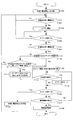
- FIG. 10 shows a processing example in which step F110 is added to the steps of FIG.
- the CPU 7 first determines the proximity operation based on the acceleration waveform as the scalar quantity in steps F100 to F104. If it is determined that the scalar amount corresponds to the proximity operation, the CPU 7 determines in step F110 whether the acceleration direction matches the antenna installation direction.
- the acceleration detection direction DET when the acceleration detection direction DET is the negative direction of the X axis, it is determined that they match. On the other hand, if the acceleration detection direction DET is the positive direction of the X axis, or the positive direction or the negative direction of the Y axis, it is determined that the acceleration direction does not match the antenna installation direction. As will be described later with reference to FIG. 11, the acceleration detection direction DET may be the positive or negative direction of the Z axis. This is a case where the front or back surface of the DSC 1 is placed on the upper surface of the wireless communication device 50. In this case, communication is often possible, and it is also assumed that the user places the communication so that it can be considered.
- the acceleration is detected when the acceleration detection direction DET is the positive direction or the negative direction of the Z axis. May be determined to coincide with the antenna installation direction. Alternatively, in this case, it may be determined that they do not match.
- the determination of step F110 in the case of the positive direction or negative direction of the Z-axis may be determined according to the performance of the device, the usage situation, and the like.
- step F110 If it is determined in step F110 that the acceleration direction does not match the antenna installation direction, the CPU 7 returns to step F101. That is, it is assumed that the user's communication intention is low, and the standby radio wave is not made dense. On the other hand, if it is determined in step F110 that the direction of acceleration matches the antenna installation direction, the CPU 7 proceeds to step F105 and subsequent steps. That is, the possibility of the user's communication intention is high and it is a communication opportunity, and the standby radio wave is set in a dense state.
- the processing in steps F105 to F109 is the same as that in the first embodiment.
- the CPU 7 recognizes the acceleration variation information as well as the three-dimensional acceleration direction information in which the acceleration is generated from the acceleration detection signal obtained by the acceleration sensor 20. Then, when it is estimated from the acceleration variation information and the acceleration direction information that the casing is in proximity to the wireless communication device 50 in a state of a specific acceleration direction, it is determined as a communication opportunity, and for a certain time (a period until the timer value Tb), Stand-by radio waves are kept dense.
- the second embodiment as in the first embodiment, it is possible to obtain power saving and an unnecessary communication prevention effect while maintaining user convenience.
- these effects can be further improved by increasing the determination accuracy of the user's communication intention.
- Communication control process A communication control process according to the third embodiment by the DSC 1 will be described.
- the third embodiment it is the same as in the second embodiment described above that the proximity operation is performed from the acceleration variation information and the acceleration direction information and the user's intention to start communication is estimated.
- the antenna direction is not correct because the casing of the DSC 1 is not properly placed. Then, a display or audio notification is made to correct the placement so that the antenna direction can be in close contact with the near field communication antenna of the communication partner.
- the direction close to the communication partner is the negative direction in the X-axis direction of DSC1, and the short-range wireless communication antenna 2 of DSC1 exists on the bottom surface of DSC1, so It will be in close contact with 50 antennas 51, and it is considered that the user intends to start communication.
- the DSC 1 may be placed in a state where it is laid down.
- the acceleration waveform as the scalar quantity is a waveform as a proximity motion, but the direction is the positive direction of the Z axis, and the user intends to start communication, but when starting communication,
- the direction of the short-range wireless communication antenna 2 is not appropriate.
- the radio wave state is not good. There is a possibility that it cannot be connected.
- the DSC 1 makes a display or audio notification that corrects the placement so that the antenna direction can be in close contact with the near field communication antenna 51 of the communication partner. This prompts the user to correct the posture of the DSC 1 and increases the possibility that the radio wave is in a good state.
- FIG. 12 shows the communication control process of the CPU 7 of the third embodiment.
- steps F100 to F104 and F105 to F109 are the same processing as in FIG. 5, and step F110 is the same processing as in FIG.
- FIG. 12 shows a processing example in which steps F111 and F112 are added to the steps of FIG.
- the CPU 7 first determines the proximity operation based on the acceleration waveform as the scalar quantity in steps F100 to F104, as in the first and second embodiments. If it is determined that the scalar amount is equivalent to the proximity operation, the CPU 7 determines whether or not the acceleration direction matches the antenna installation direction in step F110 as in the second embodiment.
- step F110 in this case, as in the example described in FIG. 7, it is determined that the acceleration detection direction DET is the same only when the acceleration detection direction DET is the negative direction of the X axis, and the other is determined not to match. To do. That is, it is determined that the antenna directions do not match when the acceleration detection direction DET is the positive direction of the X axis, the positive direction or the negative direction of the Y axis, or the positive direction or the negative direction of the Z axis. This is the case.
- step F111 determines whether the acceleration direction is perpendicular to the antenna installation direction.
- the term “perpendicular to the antenna installation direction” means, for example, a case as shown in FIG. 11, that is, a case where the acceleration detection direction DET is a positive direction or a negative direction of the Z axis.
- step F111 When it is determined in step F111 that the acceleration direction is not perpendicular to the antenna installation direction, that is, the acceleration detection direction DET is the positive direction of the X axis, or the positive direction or negative direction of the Y axis
- the CPU 7 returns to step F101. That is, it is assumed that the user's communication intention is low, and the standby radio wave is not made dense.
- step F111 if it is determined in step F111 that the direction of acceleration is perpendicular to the antenna installation direction, the CPU 7 proceeds to step F112. Then, the CPU 7 gives a caution notice to the user.
- a warning message such as “When wireless communication is performed, close the bottom face to the opposite device” is displayed, or a similar warning message voice is output from the voice output unit 12.
- a similar warning message voice is output from the voice output unit 12.
- an electronic sound is generated from the audio output unit 12. You may make it display a warning message on the display part 3 with the output of a warning message voice or an electronic sound.
- step F105 the CPU 7 proceeds to step F105.
- step F110 it is determined in step F110 that the direction of acceleration matches the antenna installation direction, the CPU 7 proceeds to step F105 and subsequent steps. That is, in these cases, the standby radio wave is set in a dense state, assuming that the user has a high possibility of communication and is a communication opportunity.
- steps F105 to F109 are the same as those in the first and second embodiments.
- the CPU 7 estimates from the acceleration fluctuation information and the acceleration direction information that the casing of the DSC 1 is brought close to an external communication device such as the wireless communication device 50 in a state of a specific acceleration direction.
- the notification output is executed according to the positional relationship between the antenna direction of the DSC 1 and the wireless communication device 50 or the like.
- the notification output is executed from the display unit 3 or the audio output unit 11.
- the user can know that the placement is not appropriate for communication, and if there is a communication intention, it can be expected that the placement of the DSC 1 is corrected. In that case, communication can be performed in a good wireless state.
- FIG. 13 shows the communication control processing of the CPU 7, but it is the same as FIG. 12 except that steps F113 and F114 are added, so only the steps F113 and F114 will be described.
- a warning message may be notified in step F112.
- the standby radio waves are kept in a dense state for a certain period of time with the limit of the timer value Tb from the time of step F105.
- the time count may reach the timer value Tb at that time.
- step F109 is a process for setting the stop state instead of the rough state, communication may not be possible even though the user corrects the posture of DSC1.
- the CPU 7 sets the standby radio wave in a dense state in step F105, starts time counting, and then monitors that the attitude of the DSC 1 is corrected from the acceleration variation information and the acceleration direction information in step F113.
- the user may correct the attitude of the DSC 1 in accordance with the notification in step F112.
- the CPU 7 proceeds to step F114 and starts the time count reaching the timer value Tb from the beginning.
- the positive direction acceleration is detected within the predetermined time Ta with respect to the acceleration detection waveform of FIG. 4 and then the negative direction acceleration is detected.
- Steps F101 to F104 of each communication control process The determination method of the proximity operation is not limited to this, and the following (a), (b), and (c) may be used.
- B Within a predetermined time Ta, positive acceleration is detected, and then negative acceleration is detected.
- the acceleration zero period is maintained for a certain period of time (that is, the state after being placed on the wireless communication device 50 is maintained), thereby determining the proximity operation.
- a positive acceleration is detected within a predetermined time Ta
- a negative acceleration is detected after a zero acceleration period.
- the acceleration zero period is maintained for a certain period of time (that is, the state after being placed on the wireless communication device 50 is maintained), thereby determining the proximity operation.
- the proximity operation is targeted to the proximity operation of “place” DSC1 on the wireless communication device 50, and this is determined from the waveform of the acceleration measurement value as shown in FIG.
- the operation mode of the user's proximity operation differs. For example, there may be a case where a counterpart device corresponding to the wireless communication device 50 is on the wall surface and a communication device corresponding to the DSC 1 or the like is brought close thereto. Therefore, the proximity operation should be determined by considering the actual type, form, usage status, and the like of the actual communication device, and performing proximity determination by detecting the waveform accordingly.
- the DSC 1 has been described as an example of the communication device.
- the present disclosure is not limited to the DSC 1, and the communication device of the present disclosure can be realized in various devices.
- a mobile phone, a video camera device, a mobile terminal device, a portable game device, an information processing device, a portable music player, a portable television receiver, and other various devices are conceivable.
- a small device that the user can hold is suitable, but not necessarily limited thereto.
- FIG. 14 shows a control unit 101, an acceleration sensor 102, a short-range wireless communication controller 103, and a short-range wireless communication antenna 104.
- a short-range wireless communication unit that performs short-range wireless communication with an external communication device
- a short-range wireless communication controller 103 and a short-range wireless communication antenna 104 are provided.
- an acceleration sensor 102 that detects acceleration due to movement of the housing is provided.
- the control unit 101 performs proximity determination and acceleration direction determination, and performs standby operation control on the short-range wireless communication controller 103.
- the control unit 101 estimates whether or not the casing of the communication device 100 is close to the external communication device 50 from the acceleration fluctuation information recognized by the acceleration detection signal from the acceleration sensor 102, and uses the estimation result. Judge the communication opportunity. And when it determines with the communication opportunity, the control part 101 is controlled so that a short distance radio
- the above-described mobile phone, video camera device, mobile terminal device, and the like correspond to the communication device of the present disclosure by including the configuration of FIG. 14 in addition to the configuration for the main functions.
- this technique can also take the following structures.
- a short-range wireless communication unit that performs short-range wireless communication with an external communication device;
- An acceleration sensor that detects acceleration due to movement of the housing; From the acceleration fluctuation information recognized by the acceleration detection signal from the acceleration sensor, it is estimated whether or not the housing is in close proximity to the external communication device, the communication opportunity is determined using the estimation result, and the communication opportunity is determined.
- Control the short-range wireless communication unit to generate a standby radio wave in a dense state, and unless the communication opportunity is determined, the generation of the standby radio wave by the short-range wireless communication unit is in a rough state.
- a communication device comprising: (2) The control unit When it is determined that the short-range wireless communication unit generates a standby radio wave in a dense state based on the determination of the communication opportunity, if a predetermined time has passed without establishment of communication with an external communication device, The communication device according to (1), wherein the generation of a standby radio wave by the distance wireless communication unit is controlled to a rough state or a stopped state. (3) When the control unit generates, as the acceleration variation information, a positive acceleration in accordance with an increase in the moving speed of the housing and a negative acceleration to stop moving the housing within a predetermined time, the housing The communication device according to (1) or (2), wherein it is determined that the device is in proximity to an external communication device.
- the control unit From the acceleration detection signal obtained by the acceleration sensor, further recognizes the three-dimensional acceleration direction information in which the acceleration occurred, Any of the above (1) to (3), which is determined as the communication opportunity when it is estimated from the acceleration variation information and the acceleration direction information that the casing is brought close to the external communication device in a state of a specific acceleration direction
- the communication apparatus as described in. (5) further comprising a notification output unit,
- the control unit From the acceleration fluctuation information and the acceleration direction information, the housing is external in the state of a specific acceleration direction.
- the communication according to (4) wherein when it is estimated that the communication device is in close proximity, the notification output unit executes a notification output according to the positional relationship between the antenna direction of the short-range wireless communication unit and the external communication device. apparatus.
- 1 DSC 2,104 Short-range wireless communication antenna
- 3 Display unit 4 Operation input unit, 5 Imaging unit, 6 Imaging signal processing unit, 7 CPU, 8 main memory, 9 storage area, 10, 103 Short-range wireless communication controller, 11 Flash memory, 12 Audio output unit, 2 0,102 Acceleration sensor, 50 Wireless communication device, 51 Short-range wireless communication antenna, 1 00 communication device, 101 control unit
Landscapes
- Engineering & Computer Science (AREA)
- Computer Networks & Wireless Communication (AREA)
- Signal Processing (AREA)
- Databases & Information Systems (AREA)
- Mobile Radio Communication Systems (AREA)
- Telephone Function (AREA)
- Transceivers (AREA)
Priority Applications (4)
| Application Number | Priority Date | Filing Date | Title |
|---|---|---|---|
| EP12812116.7A EP2733994A1 (en) | 2011-07-11 | 2012-06-11 | Communication device, communication control method |
| KR1020137034091A KR20140036254A (ko) | 2011-07-11 | 2012-06-11 | 통신 장치, 통신 제어 방법 |
| US14/125,474 US9326120B2 (en) | 2011-07-11 | 2012-06-11 | Communication apparatus and communication control method |
| CN201280033172.8A CN103636266A (zh) | 2011-07-11 | 2012-06-11 | 通信设备和通信控制方法 |
Applications Claiming Priority (2)
| Application Number | Priority Date | Filing Date | Title |
|---|---|---|---|
| JP2011152746A JP5807414B2 (ja) | 2011-07-11 | 2011-07-11 | 通信装置、通信制御方法 |
| JP2011-152746 | 2011-07-11 |
Publications (1)
| Publication Number | Publication Date |
|---|---|
| WO2013008572A1 true WO2013008572A1 (ja) | 2013-01-17 |
Family
ID=47505870
Family Applications (1)
| Application Number | Title | Priority Date | Filing Date |
|---|---|---|---|
| PCT/JP2012/064917 WO2013008572A1 (ja) | 2011-07-11 | 2012-06-11 | 通信装置、通信制御方法 |
Country Status (6)
Families Citing this family (4)
| Publication number | Priority date | Publication date | Assignee | Title |
|---|---|---|---|---|
| JP2015126410A (ja) * | 2013-12-26 | 2015-07-06 | アプリックスIpホールディングス株式会社 | 送信装置及びプログラム |
| JP6398375B2 (ja) * | 2014-06-30 | 2018-10-03 | カシオ計算機株式会社 | 通信装置、および通信方法、ならびにプログラム |
| JP6152242B2 (ja) * | 2015-04-06 | 2017-06-21 | レノボ・シンガポール・プライベート・リミテッド | 携帯式電子機器の情報セキュリティを確保する方法、携帯式電子機器および機能拡張装置 |
| US11037436B2 (en) * | 2019-03-07 | 2021-06-15 | Stmicroelectronics S.R.L. | Three-level motion detector using accelerometer device in key fob application |
Citations (4)
| Publication number | Priority date | Publication date | Assignee | Title |
|---|---|---|---|---|
| JP2008154004A (ja) | 2006-12-18 | 2008-07-03 | Sony Ericsson Mobilecommunications Japan Inc | 携帯端末及び情報通信方法 |
| JP2010068494A (ja) * | 2008-09-12 | 2010-03-25 | Olympus Imaging Corp | 携帯機器 |
| JP2011029892A (ja) | 2009-07-24 | 2011-02-10 | Sony Corp | 通信装置、通信方式の判別方法、及びプログラム |
| JP2011199918A (ja) | 2010-03-17 | 2011-10-06 | Nissan Motor Co Ltd | 永久磁石式電動モータ |
Family Cites Families (6)
| Publication number | Priority date | Publication date | Assignee | Title |
|---|---|---|---|---|
| US8391786B2 (en) * | 2007-01-25 | 2013-03-05 | Stephen Hodges | Motion triggered data transfer |
| JP2009278267A (ja) * | 2008-05-13 | 2009-11-26 | Sony Corp | 通信装置、通信システム、通信方法及びプログラム |
| JP5495582B2 (ja) | 2009-02-25 | 2014-05-21 | Necパーソナルコンピュータ株式会社 | 無線通信装置、無線通信システム、制御方法及びプログラム |
| KR101645461B1 (ko) * | 2010-01-12 | 2016-08-12 | 삼성전자주식회사 | 휴대용 단말기에서 근거리 무선 네트워크 자동 연결 방법 및 장치 |
| EP2485542B1 (en) * | 2011-02-03 | 2019-02-27 | Sony Corporation | Portable electronic device and operation method for establishing a near field communication link |
| US8965285B2 (en) * | 2011-05-13 | 2015-02-24 | Nokia Corporation | Touch inquiry |
-
2011
- 2011-07-11 JP JP2011152746A patent/JP5807414B2/ja not_active Expired - Fee Related
-
2012
- 2012-06-11 WO PCT/JP2012/064917 patent/WO2013008572A1/ja active Application Filing
- 2012-06-11 US US14/125,474 patent/US9326120B2/en not_active Expired - Fee Related
- 2012-06-11 KR KR1020137034091A patent/KR20140036254A/ko not_active Withdrawn
- 2012-06-11 CN CN201280033172.8A patent/CN103636266A/zh active Pending
- 2012-06-11 EP EP12812116.7A patent/EP2733994A1/en not_active Withdrawn
Patent Citations (4)
| Publication number | Priority date | Publication date | Assignee | Title |
|---|---|---|---|---|
| JP2008154004A (ja) | 2006-12-18 | 2008-07-03 | Sony Ericsson Mobilecommunications Japan Inc | 携帯端末及び情報通信方法 |
| JP2010068494A (ja) * | 2008-09-12 | 2010-03-25 | Olympus Imaging Corp | 携帯機器 |
| JP2011029892A (ja) | 2009-07-24 | 2011-02-10 | Sony Corp | 通信装置、通信方式の判別方法、及びプログラム |
| JP2011199918A (ja) | 2010-03-17 | 2011-10-06 | Nissan Motor Co Ltd | 永久磁石式電動モータ |
Also Published As
| Publication number | Publication date |
|---|---|
| US20140113566A1 (en) | 2014-04-24 |
| EP2733994A1 (en) | 2014-05-21 |
| US9326120B2 (en) | 2016-04-26 |
| JP2013021475A (ja) | 2013-01-31 |
| KR20140036254A (ko) | 2014-03-25 |
| JP5807414B2 (ja) | 2015-11-10 |
| CN103636266A (zh) | 2014-03-12 |
Similar Documents
| Publication | Publication Date | Title |
|---|---|---|
| US9575508B2 (en) | Impact and contactless gesture inputs for docking stations | |
| WO2018039881A1 (zh) | 充电保护方法、终端及充电器 | |
| JP5807414B2 (ja) | 通信装置、通信制御方法 | |
| CN112068760A (zh) | 终端、显示方法、显示装置及存储介质 | |
| WO2019047862A1 (zh) | 一种指纹采集方法及终端设备、存储介质 | |
| WO2019129092A1 (zh) | 一种降帧率拍照方法、移动终端及存储介质 | |
| CN107681727B (zh) | 电子设备的控制方法及装置 | |
| CN114785766B (zh) | 智能设备的控制方法、终端及服务器 | |
| CN112042176B (zh) | 电子装置和控制电子装置的方法 | |
| CN109873636B (zh) | 频率调整方法和移动终端 | |
| US9191896B2 (en) | Communication apparatus and communication control method | |
| JP6133692B2 (ja) | 撮像機器及び電子機器の制御プログラム | |
| EP2996316B1 (en) | Methods and systems for communication management between an electronic device and a wearable electronic device | |
| CN105120158B (zh) | 移动终端的拍摄方法及装置 | |
| CN111246061B (zh) | 移动终端、拍摄模式的检测方法及存储介质 | |
| WO2017049552A1 (zh) | 终端设备和控制充电的方法 | |
| CN111868674A (zh) | 便携信息终端 | |
| CN105100361A (zh) | 移动终端的录音方法及装置 | |
| WO2017092039A1 (zh) | 提供、获取位置信息的方法、装置以及设备 | |
| JP2013115633A (ja) | 情報端末およびその制御用プログラム | |
| CN106379232B (zh) | 携带物品提醒的方法及装置 | |
| CN108259727A (zh) | 一种景深图像生成方法及移动终端 | |
| JP2019041187A (ja) | 携帯端末及びシステム | |
| JP2019062260A (ja) | 被制御装置、通信制御方法、及びプログラム | |
| CN106852048A (zh) | 电子装置的壳体组件及电子装置 |
Legal Events
| Date | Code | Title | Description |
|---|---|---|---|
| 121 | Ep: the epo has been informed by wipo that ep was designated in this application |
Ref document number: 12812116 Country of ref document: EP Kind code of ref document: A1 |
|
| WWE | Wipo information: entry into national phase |
Ref document number: 14125474 Country of ref document: US |
|
| ENP | Entry into the national phase |
Ref document number: 20137034091 Country of ref document: KR Kind code of ref document: A |
|
| WWE | Wipo information: entry into national phase |
Ref document number: 2012812116 Country of ref document: EP |
|
| NENP | Non-entry into the national phase |
Ref country code: DE |