EP2733994A1 - Communication device, communication control method - Google Patents
Communication device, communication control method Download PDFInfo
- Publication number
- EP2733994A1 EP2733994A1 EP12812116.7A EP12812116A EP2733994A1 EP 2733994 A1 EP2733994 A1 EP 2733994A1 EP 12812116 A EP12812116 A EP 12812116A EP 2733994 A1 EP2733994 A1 EP 2733994A1
- Authority
- EP
- European Patent Office
- Prior art keywords
- acceleration
- communication
- wireless communication
- short
- range wireless
- Prior art date
- Legal status (The legal status is an assumption and is not a legal conclusion. Google has not performed a legal analysis and makes no representation as to the accuracy of the status listed.)
- Withdrawn
Links
- 238000004891 communication Methods 0.000 title claims abstract description 383
- 238000000034 method Methods 0.000 title claims description 30
- 230000001133 acceleration Effects 0.000 claims abstract description 192
- 238000013459 approach Methods 0.000 claims abstract description 76
- 238000001514 detection method Methods 0.000 claims abstract description 48
- 230000033001 locomotion Effects 0.000 claims abstract description 15
- 101100223811 Caenorhabditis elegans dsc-1 gene Proteins 0.000 description 100
- 238000012545 processing Methods 0.000 description 42
- 230000008569 process Effects 0.000 description 14
- 238000009434 installation Methods 0.000 description 13
- 230000015654 memory Effects 0.000 description 13
- 238000005259 measurement Methods 0.000 description 12
- 238000010586 diagram Methods 0.000 description 10
- 230000004044 response Effects 0.000 description 8
- 230000000694 effects Effects 0.000 description 6
- 230000006870 function Effects 0.000 description 6
- 230000005540 biological transmission Effects 0.000 description 5
- 238000012544 monitoring process Methods 0.000 description 5
- 238000005516 engineering process Methods 0.000 description 3
- 230000007246 mechanism Effects 0.000 description 3
- 230000009467 reduction Effects 0.000 description 3
- 230000009471 action Effects 0.000 description 2
- 230000008859 change Effects 0.000 description 2
- 238000005401 electroluminescence Methods 0.000 description 2
- 230000010365 information processing Effects 0.000 description 2
- 230000010355 oscillation Effects 0.000 description 2
- 230000002265 prevention Effects 0.000 description 2
- 230000009466 transformation Effects 0.000 description 2
- 230000008901 benefit Effects 0.000 description 1
- 238000006243 chemical reaction Methods 0.000 description 1
- 230000000295 complement effect Effects 0.000 description 1
- 238000007906 compression Methods 0.000 description 1
- 238000012937 correction Methods 0.000 description 1
- 230000002708 enhancing effect Effects 0.000 description 1
- 230000001771 impaired effect Effects 0.000 description 1
- 230000000977 initiatory effect Effects 0.000 description 1
- 239000004973 liquid crystal related substance Substances 0.000 description 1
- 229910044991 metal oxide Inorganic materials 0.000 description 1
- 150000004706 metal oxides Chemical class 0.000 description 1
- 230000004048 modification Effects 0.000 description 1
- 238000012986 modification Methods 0.000 description 1
- 230000000737 periodic effect Effects 0.000 description 1
- 239000004065 semiconductor Substances 0.000 description 1
- 230000001360 synchronised effect Effects 0.000 description 1
Images


Classifications
-
- H—ELECTRICITY
- H04—ELECTRIC COMMUNICATION TECHNIQUE
- H04W—WIRELESS COMMUNICATION NETWORKS
- H04W8/00—Network data management
- H04W8/005—Discovery of network devices, e.g. terminals
-
- H—ELECTRICITY
- H04—ELECTRIC COMMUNICATION TECHNIQUE
- H04W—WIRELESS COMMUNICATION NETWORKS
- H04W88/00—Devices specially adapted for wireless communication networks, e.g. terminals, base stations or access point devices
- H04W88/02—Terminal devices
-
- H—ELECTRICITY
- H04—ELECTRIC COMMUNICATION TECHNIQUE
- H04W—WIRELESS COMMUNICATION NETWORKS
- H04W4/00—Services specially adapted for wireless communication networks; Facilities therefor
- H04W4/80—Services using short range communication, e.g. near-field communication [NFC], radio-frequency identification [RFID] or low energy communication
-
- H—ELECTRICITY
- H04—ELECTRIC COMMUNICATION TECHNIQUE
- H04W—WIRELESS COMMUNICATION NETWORKS
- H04W52/00—Power management, e.g. Transmission Power Control [TPC] or power classes
- H04W52/02—Power saving arrangements
-
- H—ELECTRICITY
- H04—ELECTRIC COMMUNICATION TECHNIQUE
- H04W—WIRELESS COMMUNICATION NETWORKS
- H04W52/00—Power management, e.g. Transmission Power Control [TPC] or power classes
- H04W52/02—Power saving arrangements
- H04W52/0209—Power saving arrangements in terminal devices
- H04W52/0251—Power saving arrangements in terminal devices using monitoring of local events, e.g. events related to user activity
- H04W52/0254—Power saving arrangements in terminal devices using monitoring of local events, e.g. events related to user activity detecting a user operation or a tactile contact or a motion of the device
-
- Y—GENERAL TAGGING OF NEW TECHNOLOGICAL DEVELOPMENTS; GENERAL TAGGING OF CROSS-SECTIONAL TECHNOLOGIES SPANNING OVER SEVERAL SECTIONS OF THE IPC; TECHNICAL SUBJECTS COVERED BY FORMER USPC CROSS-REFERENCE ART COLLECTIONS [XRACs] AND DIGESTS
- Y02—TECHNOLOGIES OR APPLICATIONS FOR MITIGATION OR ADAPTATION AGAINST CLIMATE CHANGE
- Y02D—CLIMATE CHANGE MITIGATION TECHNOLOGIES IN INFORMATION AND COMMUNICATION TECHNOLOGIES [ICT], I.E. INFORMATION AND COMMUNICATION TECHNOLOGIES AIMING AT THE REDUCTION OF THEIR OWN ENERGY USE
- Y02D30/00—Reducing energy consumption in communication networks
- Y02D30/70—Reducing energy consumption in communication networks in wireless communication networks
Definitions
- the present disclosure relates to a communication apparatus and communication control method that performs a short-range wireless communication.
- a short-range wireless communication technology such as Bluetooth or TransferJet has been known in this field.
- transmission of a radio signal for detection is used in order to detect a communication counterpart capable of wireless communication.
- Patent Literature 1 discloses TransferJet as an example of the short-range wireless communication.
- a radio signal for detecting an opposite communication device is defined as a polling signal, and one communication device sends a polling signal and the other communication device replies a response signal according to the polling signal.
- the polling signal allows preparation condition when both communication devices initiate a data exchange between them to be decided and also enables processes performed between them to be synchronized.
- the polling signal is discontinuously sent at a given polling interval.
- a radio signal for detecting an opposite communication device (referred to herein as “standby radio signal”) is periodically transmitted.
- This periodic transmission of the radio signal is used to automatically detect an opposite communication device and then initiates the communication by bring an originator communication device and the target communication device into close proximity, thereby realizing an intuitive operation feel, particularly in the short-range wireless communication.
- Patent Literature 2 describes a scheme in which acceleration detection means is installed in a wireless communication device and, in a case where the acceleration by user's action is detected, communication means is controlled. To be more specific, it is assumed that communication processing is operated in a case where the acceleration by user's walking or the like is detected by the acceleration detection means (for example, acceleration sensor), the communication processing is stopped in a case where the acceleration is not detected.
- the acceleration detection means for example, acceleration sensor
- the communication processing is started and stopped in response to a response of the acceleration sensor by the user's action, even in a case where the user has no intention to start communication, the communication is started when the wireless communication device detects the acceleration. For example, even in a case where the user carries the wireless communication device, it is considered that communication is started. As a result, there is a possibility that unintended communication is started and unnecessary power is consumed.
- Patent Literature 3 describes a scheme in which acceleration detection means is installed in a wireless communication device and a function to perform communication between communication devices is invoked using, as a trigger, detection of predetermined oscillation motion added to the close wireless communication devices.
- the user requests two kinds of operations to start communication, and, since the later operation is obviously a specific operation specialized in communication devices, the operation is performed after the user recognizes this beforehand. That is, the convenience of starting communication only by adjacency is impaired.
- a communication apparatus including a short-range wireless communication unit that performs short-range wireless communication with an external communication device, an acceleration sensor that detects an acceleration by a movement of a chassis, and a control unit that estimates whether the chassis approaches the external communication device, from acceleration variation information recognized by an acceleration detection signal from the acceleration sensor, performs a communication opportunity determination using a result of the estimation, controls the short-range wireless communication unit to generate a standby radio wave in a dense state in a case where a communication opportunity is determined, and controls generation of the standby radio wave by the short-range wireless communication unit to be in a rough state or a stopped state in a case other than the case of determining the communication opportunity.
- the control unit controls the generation of the standby radio wave by the short-range wireless communication unit to be in the rough state or the stopped state.
- a communication control method of a communication apparatus including a short-range wireless communication unit that performs short-range wireless communication with an external communication device and an acceleration sensor that detects an acceleration by a movement of a chassis, the communication control method including estimating whether the chassis approaches the external communication device, from acceleration variation information recognized by an acceleration detection signal from the acceleration sensor, performing a communication opportunity determination using a result of the estimation, and generating a standby radio wave in a dense state from the short-range wireless communication unit in a case where a communication opportunity is determined, and setting generation of the standby radio wave by the short-range wireless communication unit to a rough state or a stopped state in a case other than the case of determining the communication opportunity.
- acceleration variation information by an acceleration sensor according to the movement of a communication device chassis whether the chassis is close to an external communication device is estimated and whether a communication opportunity is provided is determined. That is, a short-range state is determined by the acceleration variation observed when the user performs an operation of making the communication apparatus chassis approach the external communication device of the communicating party.
- a communication opportunity provided by user's intention is estimated at a relatively high accuracy, and, by keeping standby radio waves in a dense state according thereto, the communication start is prepared.
- the present disclosure in communication apparatuses that perform short-range wireless communication, in a case where the user has no intention to start communication by the communication device, it is possible to suppress a situation of communication connection and reduce power required for connection standby. Moreover, since a special operation load is not applied to the user especially, it is possible to maintain the user's convenience.
- DSC digital still camera
- FIG. 1A is a front side perspective view illustrating an appearance of a DSC 1 according to an embodiment.
- FIG. 1B is a rear side (operation side) plan view illustrating an appearance of the DSC 1.
- the DSC 1, as shown in FIG. 1A includes a short-range wireless communication antenna 2 at a lower part of the front side.
- the DSC 1 may be configured to include a removable (detachable) communication module (a module including a short-range wireless communication controller 10 or a storage region for communication, which will be described later) which is equipped with the short-range wireless communication antenna 2.
- a removable (detachable) communication module a module including a short-range wireless communication controller 10 or a storage region for communication, which will be described later
- the DSC 1, as shown in FIG. 1B includes a display unit 3 on the rear surface.
- the display unit 3 may be configured to include a liquid crystal display (LCD), an organic electro-luminescence (EL) display, or similar display device.
- LCD liquid crystal display
- EL organic electro-luminescence
- Operating portions constituting an operation input unit 4 are also provided to the DSC 1.
- the operating portions may include a playback menu start button 41, a decision button 42, a cross key 43, a cancel button 44, a zoom key 45, a slide key 46, a shutter button 47, and so on.
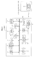
- FIG. 2 is a block diagram illustrating an internal configuration of the DSC 1 and a state that the DSC 1 and other electronic device (wireless communication device 50) are connected to each other using a short-range wireless communication.
- the DSC 1 and the wireless communication device 5 can connect and communicate with each other using a short-range wireless communication.
- a short-range wireless communication in addition to Bluetooth or TransferJet, other short-range wireless communication technologies may be used.
- the DSC 1 includes an image capturing unit 5, an image capturing signal processing unit 6, a central processing unit (CPU) 7, a main memory 8, a storage region 9, a short-range wireless communication controller 10, a flash memory 11, and an acceleration sensor 20, in addition to the short-range wireless communication antenna 2, the display unit 3 and the operation input unit 4, shown in FIG. 1 .
- These components can transmit and receive control signals or image capturing data between each other through a system bus 14.
- the short-range wireless communication antenna 2, the storage region 9, and the short-range wireless communication controller 10 may be separately provided as a removable module without being embedded into the DSC 1.
- the image capturing unit 5 includes image sensors, a lens system, a drive mechanism, and a diaphragm mechanism.
- the image sensors receive a light reflected from a subject and convert the received light into electrical signals.
- the lens system condenses a light reflected from the subject onto the image sensors.
- the drive and diaphragm mechanisms perform a focusing or zooming by moving a lens.
- the components of the image capturing unit 5 are driven in response to a control signal from the CPU 7.
- the image sensors may be a charge coupled device (CCD), a complementary metal oxide semiconductor (CMOS), and so on.
- CCD charge coupled device
- CMOS complementary metal oxide semiconductor
- the image capturing signal processing unit 6 performs an analog-digital (A/D) conversion, the ISO gain setting, and other various signal processes on the electrical signal obtained by the image sensors of the image capturing unit 5, thereby generating the image capturing signal.
- A/D analog-digital
- the image capturing signal processing unit 6 may create an image file including a still or moving image by performing a compression process or similar process on the image capturing signal.
- the image capturing signal processing unit 6 may transmit a through image to the display unit 3 on which the through image is displayed.
- the display unit 3 displays an image before capturing a subj ect (a through image), contents such as a captured still or moving image file, a menu for operation (graphical user interface: GUI), and so on, in response to a control signal from the CPU 7.
- a subj ect a through image
- contents such as a captured still or moving image file
- a menu for operation graphical user interface: GUI
- the operation input unit 4 functions as an input means for inputting user operations and sends a signal according to the inputted operation to the CPU 7 and so on.
- the various operating portions as the operation input unit 4 are shown in FIG. 1 , but it also may be possible to provide a touch panel in which the operation input unit 4 is integrated with the display unit 3.
- the main memory 8 may be a volatile memory such as a random access memory (RAM).
- the main memory 8 also temporarily stores data or program as a working area when various data is processed by the CPU 7. For example, when an image data is processed in the image capturing signal processing unit at a timing the shutter button is pressed, the image data is read out by the main memory 8 and then written to the storage region 9.
- the flash memory (non-volatile memory) 11 stores an operation system (OS) for controlling the components, applications necessary to communicate using the short-range wireless communication, or the like, except for contents files such as an image file.
- OS operation system
- the storage region 9 may be a non-volatile memory and functions as storage means for storing contents files such as an image file, attribute information and thumbnail image of the image file, and so on.
- the image file is stored in the form of a joint photographic experts group (JPEG), a tagged image file format (TIFF), a graphics interchange format (GIF), and so on.
- JPEG joint photographic experts group
- TIFF tagged image file format
- GIF graphics interchange format
- the storage region 9 may be in the form of a memory card detachably connected to the DSC 1 or may be embedded into the DSC 1.
- the storage region 9 may be implemented as a portable flash memory, a hard disk drive (HDD), or the like.
- the short-range wireless communication antenna 2 receives radio signals emitted from other electronic devices and converts the radio signals into signals.
- the short-range wireless communication antenna 2 also performs a transmission of a standby radio signal or a transmission of a wireless radio wave signal to send data to other electronic devices.
- the short-range wireless communication controller 10 controls the transmission or reception of signals using the short-range wireless communication antenna 2 based on a connection protocol of the short-range wireless communication in cooperation with the CPU 7.
- the acceleration sensor 20 can detect the acceleration amount and acceleration direction of a chassis by the physical movement of the DSC 1 and convert them into a detection signal.
- the CPU 7 can read the value of the detection signal, and it is assumed that it is possible to use the value of the detection signal for various intended purposes.
- the CPU 7 generally controls the entire DSC 1 by executing the program stored in the flash memory 11 or similar memory device.
- the CPU 7 may control operations of the units including an image capturing operation, a playback operation of a captured image file, and a short-range wireless communication operation with an external device, and so on, according to user operations.
- the system bus 14 can connect the units such as the CPU 7 to each other and allows the units to exchange signals between each other.
- FIG. 2A illustrates a speech output unit 11 in the DSC 1. This is installed in a case where voice announcement (such as electronic sound and message speech output) to the user is performed in the third and fourth embodiments described later.
- the speech output unit 11 outputs the message speech or the electronic sound on the basis of the control of the CPU 7.
- the announcement to the user can be performed as message display in the display unit 3.
- the speech output unit 11 may not be installed.
- the wireless communication device 50 which performs the short-range wireless communication with the DSC 1 includes units capable of processing information, such as a CPU, a ROM, a RAM, a display unit, an operation input unit, and so on, which are not shown, in addition to the short-range wireless communication antenna 51.
- the signal which is received by the wireless communication device 5 is converted through the short-range wireless communication antenna 51.
- an arithmetic process or the like is performed by the CPU. This allows the wireless communication device 50 to be connected to the DSC 1 using the short-range wireless communication and to establish the communication.
- the DSC 1 is in a standby state, which will be described later. In the state that the communication between them is established, the DSC 1 can transmit information such as contents files included in the DSC 1 to the wireless communication device 5.
- a communication control process of the first embodiment will be described with reference to a short-range wireless communication operation by the DSC 1.
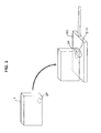
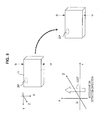
- FIG. 3 schematically illustrates the DSC 1 and the wireless communication device 50.
- the DSC 1 can be placed on the wireless communication device 50.
- the short-range wireless communication is performed between the DSC 1 and the wireless communication device 50.
- the arrangement position in the chassis of the short-range wireless communication antenna 2 is illustrated as antenna position 2P
- the arrangement position of the short-range wireless communication antenna 51 in the wireless communication device 50 is illustrated as antenna position 51P.
- the wireless communication device 50 illustrated in FIG. 3 is connected to, for example, a personal computer, an image edit apparatus, an image storage unit and other information processing devices or image processing devices, and can forward content files or the like transmitted from the DSC 1 to these devices.
- the wireless communication device 50 may be a tablet-type personal computer and the wireless communication device 50 itself may be the forwarding destination of the contents files or the like.
- the communication initiates by placing the DSC 1 on the wireless communication device 5 and by causing the DSC 1 to be close to the wireless communication device 5.
- proximity operation The operation in which a user holds the DSC 1 and places on the wireless communication device 50 to communicate between them is referred to as "proximity operation" hereinafter.
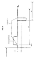
- a detection signal waveform from the acceleration sensor 20 in the DSC 1 shows a specific shape as illustrated in FIG. 4 .
- FIG. 4 it is assumed that the user starts the approach operation at the time of time axis TM0, and velocity change V and acceleration change AV in this case are illustrated.
- the CPU 7 of the DSC 1 can know that the case of the DSC 1 is subjected to the approach operation, from acceleration variation information that can be observed as a detection signal waveform of this value.
- the DSC 1 causes the generation of standby radio waves to be in a rough state or stopped state at the normal time.
- the normal time denotes a period in which the DSC 1 is in a power-on state but it is not especially determined to perform short-range wireless communication.
- the DSC 1 when determining that the approach operation with respect to the wireless communication device 50 is performed, the DSC 1 generates standby radio waves in the short-range wireless communication in the dense state for a certain period of time.
- the standby radio waves are set to be in a non-dense or stopped state.
- to cause the standby radio waves to be a rough state means to lengthen a period interval (polling period) to send standby radio waves.
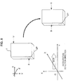
- FIG. 6A illustrates an example of a polling period to generate standby radio waves
- the dense state denotes a case where polling period P is short
- the rough state denotes a case where polling period P is long.
- the dense state it is easy to detect a communicating party.
- the rough state denotes a state where it is less likely to detect the communicating party, it does not mean that the detection is completely stopped.
- the stopped state denotes a state where the generation of standby radio waves is completely stopped, and, in this case, the communicating party is not detected.
- the standby radio waves at the normal time are set to be in the rough state or the standby radio waves at the normal time are set to the stopped state, and they should be set according to the features and characteristics of a device on which a function is mounted.
- the specific values of polling period P in the dense state and the rough state should also be set according to the features and characteristics of a device.
- the dense state and the rough state described below denote a state to shorten polling period P and a state to lengthen polling period P, respectively, as the DSC 1 of this example, and specific period values are not limited.
- the CPU 7 controls standby radio waves at the normal time. That is, the CPU 7 instructs the stopped state or rough state of standby radio wave generation to the short-range wireless communication controller 10. In response to this, the short-range wireless communication controller 10 sets the standby radio waves to a stopped state or a rough state.
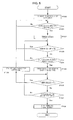
- step F101 the CPU 7 acquires an acceleration detection signal (acceleration measurement value) from the acceleration sensor 20 and monitors whether the acceleration value is equal to or greater than constant threshold thA.
- FIG. 4 illustrates one example of threshold thA and threshold thB described later.
- An acquisition method of the detection value of the acceleration sensor 20 may be a method of acquiring the value of the acceleration sensor 20 from the CPU 7 at regular intervals or may be a method of notifying the value by interruption or the like from the acceleration sensor 20.
- step F101 the CPU 7 proceeds to step F102 in a case where the acceleration measurement value exceeds threshold thA.
- the CPU 7 starts a time count using timer value Ta as a limit.
- the CPU 7 continues the monitoring processing in steps F103 and F104 while ongoingly acquiring the acceleration measurement value of the acceleration sensor 20.
- step F103 whether the time count reaches timer value Ta is monitored. Moreover, in step F104, whether the value equal to or less than constant threshold thB is acquired as an acceleration measurement value is monitored.
- the CPU 7 returns from step F103 to the monitoring processing in F101.
- the CPU 7 detects in step F104 that the acceleration measurement value is equal to or less than threshold B, at this timing, the CPU 7 estimates that an approach operation is performed, and thereby determines that a communication opportunity is provided.
- the DSC 1 determines that the chassis approaches the wireless communication device 50 and the communication opportunity is provided.
- the waveform shape illustrated in FIG. 4 is determined and estimated as the approach operation.
- step S105 the CPU 7 newly starts the time count using timer value Tb as a limit.
- the CPU 7 instructs the short-range wireless communication controller 10 to generate standby radio waves in a dense state.
- the short-range wireless communication controller 10 performs an operation that shortens the polling period from the short-range wireless communication antenna 2 and generates standby radio waves.
- the short-range wireless communication controller 10 tries communication connection with the wireless communication device 50 of the other party.
- the CPU 7 monitors whether the time count reaches timer value Tb in step F106. Moreover, in step F107, whether the device of the communicating party is detected is monitored.
- timer value Tb defines the upper limit time of a detection period of the communication destination while the standby radio waves are generated in a dense state.
- step F107 In a case where the CPU 7 detects the communicating party device in step F107, it proceeds to step F108, and the CPU 7 controls the short-range wireless communication controller 10 and starts wireless communication.
- the CPU 7 proceeds from step F106 to F109 and instructs the stopped state or rough state of standby radio wave generation to the short-range wireless communication controller 10.
- the short-range wireless communication controller 10 sets the standby radio waves to the stopped state or the rough state. Subsequently, the CPU 7 returns to the monitoring processing in step F101.
- polling period P has been previously described in FIG. 6A , it is easy to detect the communicating party in the dense state but it is not easy to detect the communicating party in the rough state. In the stopped state, the communicating party is not detected. Meanwhile, although the relationship between the power consumption and the polling period is illustrated in FIG. 6B , the power consumption related to standby increases as it becomes the dense state in which polling period P is short. There is little power consumption in the rough state and three is no power consumption related to standby radio waves in the stopped state.
- the approach operation is detected to determine the communication opportunity and set the standby radio waves to the dense state while they are set to the rough state or the stopped state in other cases, such that it is possible to increase a possibility of communication connection only in a case where there is a high possibility that the user intends short-range wireless communication.
- it is possible to decrease the possibility of communication connection which is suitable in the point of preventing the situation in which unintended communication is performed as much as possible.
- the dense state with large power consumption is set only in a case where there is a high possibility that the user intends the short-range wireless communication, and the rough state with less power consumption or the stopped state without power consumption related to standby radio waves is set in other cases, which is effective for reduction of the power consumption related to the standby.
- the approach operation is not necessarily limited to an "operation to place the DSC 1 on the wireless communication device 50."
- an operation to place the DSC 1 on the desk or the like by the user is performed multiple times in the normal user use.
- the standby radio waves are set to the dense state when it is determined that there is a high possibility that the user intends the short-range wireless communication, even if the user does not actually intend the communication, they do not indefinitely remain in the dense state wastefully but are returned to the rough state or the stopped state.
- the CPU 7 cannot detect it.
- the rough state is normally set and it is suitable that at least a possibility of being able to establish communication connection is left.
- the acceleration sensor 20 detects the acceleration value of the waveform illustrated in FIG. 4 and detects the three-dimensional generation direction of acceleration.
- the acceleration sensor 20 does not detect the acceleration value as the scalar quantity value but detects the acceleration value as the vector quantity value, and can detect the acceleration amount in the three-dimensional direction.
- the acceleration detection direction DET in the negative direction of the X axis is detected.
- arrow U shows the top surface side of the DSC 1
- arrow B shows the bottom surface side of the DSC 1.
- the position of the short-range wireless communication antenna 2 is assumed to be arranged in the bottom surface side in the DSC chassis as illustrated by position 2P.
- the acceleration direction is simultaneously detected at that time to determine in which direction the approach operation is performed.
- the direction in which the DSC 1 approaches the wireless communication device 50 of the communicating party is the negative direction of the X axis direction of the DSC 1. Since the short-range wireless communication antenna 2 of the DSC 1 exists on the bottom surface of the DSC 1, it becomes adjacent to the wireless communication antenna 51 (position 51P) of the wireless communication device 5, and it is considered that the user has an intention to start communication.
- the acceleration in the vertically opposite direction to FIG. 7 may be detected in which acceleration detection direction DET is the positive direction in the X axis direction.
- the waveform of acceleration as the scalar quantity is similar to the waveform as the approach operation.
- the direction in which the wireless communication device 50 approaches is the top surface side opposite to the installation direction (position 2P that is the bottom surface side) of the short-range wireless communication antenna 2 of the DSC 1.
- acceleration detection direction DET is the positive direction in the Y axis direction.
- the waveform of acceleration as the scalar quantity is similar to the waveform as the approach operation, but the direction does not correspond to the installation direction (position 2P) of the short-range wireless communication antenna 2 of the DSC 1. Normally, it is not considered that the user longitudinally puts the DSC 1 and performs the approach operation, and it is considered that there is a low possibility that the user has an intention to start communication.
- the acceleration direction at the time of performing the approach operation with a communication start is decided by the position of the antenna in the short-range wireless communication device, and, in a case where the direction matches the direction of the acceleration at the time the approach operation is detected, it is possible to determine that the user has an intention to start communication.
- standby radio waves are sent in the dense state for a certain period of time. Otherwise, the standby radio waves are set to the rough state or the stopped state. By this means, it is possible to prevent user's unintended communication and reduce the power consumed for the standby radio waves.
- FIG. 10 illustrates communication control processing of the CPU 7 according to the second embodiment.
- FIG. 10 shows a processing example in which step F110 is added to the steps of FIG. 5 .
- the CPU 7 determines the approach operation by the waveform of acceleration as the scalar quantity in steps F100 to F104. Subsequently, in a case where it is determined that it corresponds to the approach operation with respect to the scalar quantity, in step F110, the CPU 7 determines whether the acceleration direction matches the antenna installation direction.
- acceleration detection direction DET is the negative direction of the X axis, it is determined that they are matched.
- acceleration detection direction DET is the positive direction of the X axis
- acceleration detection direction DET is the positive or negative direction of the Z axis. It is a case where the front surface or back surface of the DSC 1 is put on the upper surface of the wireless communication device 50. In this case, communication is possible in many cases, or a case is assumed where it is put as above taking into account that the user can perform communication. Therefore, in a case where the short-range wireless communication antenna 2 of the DSC 1 is assumed to be arranged and have performance such that communication is possible in the state as illustrated in FIG. 11 , when acceleration detection direction DET is the positive or a negative direction of the Z axis, it may be determined that the acceleration direction matches the antenna installation direction. Alternatively, in that case, it may be determined that they are not matched. In the case of the positive or negative direction of the Z axis, the determination in step F110 may be decided according to the performance and use status or the like of the device.
- step F110 In a case where it is determined in step F110 that the acceleration direction does not match the antenna installation direction, the CPU 7 returns to step F101. That is, a possibility of user's communication intention is assumed to be low and standby radio waves are not set to the dense state.
- step F110 determines that the acceleration direction matches the antenna installation direction
- the CPU 7 proceeds to step F105. That is, it is regarded that there is a high possibility of user's communication intention and a communication opportunity is provided, the standby radio waves are set to the dense state.
- the processing in steps F105 to F109 is similar to the first embodiment.
- the CPU 7 recognizes acceleration variation information and three-dimensional acceleration direction information about generated acceleration, from an acceleration detection signal acquired by the acceleration sensor 20. Subsequently, from the acceleration variation information and the acceleration direction information, in a case where it is estimated that the chassis approaches the wireless communication device 50 in a specific acceleration direction state, a communication opportunity is determined, and the standby radio waves are set to the dense state for a certain period of time (period to timer value Tb).
- this second embodiment similar to the first embodiment, it is possible to save the power and acquire an unnecessary communication prevention effect while maintaining the user's convenience. Especially, by enhancing the determination accuracy of user's communication intention, it is possible to further improve these effects.
- execution of the short-range operation and estimation of user's intention to start communication are performed from the acceleration variation information and the acceleration direction information.
- execution of the short-range operation and estimation of user's intention to start communication are performed from the acceleration variation information and the acceleration direction information.
- the third embodiment in a case where it is considered that the user has an intention to start communication, since the way of putting the chassis of the DSC 1 is not adequate, it is detected that the antenna direction is not correct, and display or voice announcement is performed such that the way of putting it is corrected to make the antenna direction adhere to a short-range wireless communication antenna of the communicating party.
- the direction to approach the communicating party is the negative direction of the X axis direction of the DSC 1 and the short-range wireless communication antenna 2 of the DSC 1 exists on the bottom surface of the DSC 1, it approaches the antenna 51 of the wireless communication device 50 and it is considered that the user has an intention to start communication.
- the DSC 1 is put in a horizontal manner.
- the waveform of acceleration as the scalar quantity is a waveform as the approach operation
- the direction is the positive direction of the Z axis and the user has an intention to start communication
- the third embodiment in such a case, display or voice announcement is performed such that the way of putting it is corrected to make the antenna direction adhere to the short-range wireless communication antenna 51 of the communicating party.
- the user is encouraged to correct the posture of the DSC 1 and increase a possibility of putting radio waves into a good state.
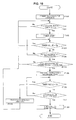
- FIG. 12 illustrates communication control processing of the CPU 7 according to the third embodiment.
- steps F100 to F104 and F105 to F109 are similar processing to FIG. 5 and step F110 is similar processing to FIG. 10 .
- FIG. 12 is a processing example in which steps F111 and F112 are added to the steps of FIG. 10 .
- the CPU 7 determines an approach operation by the waveform of acceleration as the scalar quantity in the same way as the first and second embodiments. Subsequently, in a case where it is determined that the scalar quantity corresponds to the approach operation, similar to the second embodiment, the CPU 7 determines in step F110 whether the acceleration direction matches the antenna installation direction.
- step F110 in this case, as illustrated in the example of FIG. 7 , it is determined that they are matched only in a case where acceleration detection direction DET is the negative direction of the X axis, and, otherwise, it is determined that they are not matched.
- acceleration detection direction DET is the positive direction of the X axis, the positive or negative direction of the Y axis or the positive or negative direction of the Z axis.
- step F111 determines whether the acceleration direction is vertical to the antenna installation direction.
- To be vertical to the antenna installation direction denotes, for example, a case like FIG. 11 , that is, a case where acceleration detection direction DET is the positive or negative direction of the Z axis.
- step F111 in a case where it is determined that the acceleration direction is not vertical to the antenna installation direction, that is, in a case where acceleration detection direction DET is the positive direction of the X axis or the positive or negative direction of the Y axis, the CPU 7 returns to step F101. That is, it is determined that there is a low possibility of user's communication intention, the standby radio waves are not set to the dense state.
- step F111 determines that the acceleration direction is vertical to the antenna installation direction
- the CPU 7 proceeds to step F112. Subsequently, the CPU 7 performs caution announcement for the user.
- an alert message like "in the case of performing wireless communication, please make the bottom surface approach the facing device” is displayed, or similar alert message speech is output from the speech output unit 12.
- electronic sound is generated from the speech output unit 12.
- Alert message display in the display unit 3 may be performed together with an output of the alert message speech and the electronic sound.
- step F105 the CPU 7 proceeds to step F105.
- the CPU 7 in a case where it is determined in step F110 that the acceleration direction matches the antenna installation direction, the CPU 7 also proceeds to step F105 and subsequent steps.
- steps F105 to F109 is similar to the first and second embodiments.
- an announcement output is performed according to the positional relationship between the antenna direction of the DSC 1 and the wireless communication device 50 or the like.
- a communication opportunity is determined and an alert output from the display unit 3 or the speech output unit 11 is performed.
- the user can know that the putting way is not adequate for communication, and in a case where there is a communication intention, it is expected to correct the way of putting the DSC 1. In that case, it is assumed that it is possible to perform communication in a good wireless state.
- the fourth embodiment is described. Although the fourth embodiment is substantially the same as the above-mentioned third embodiment, processing corresponding to a case where the user corrects the way of putting the DSC 1 is added.
- FIG. 13 illustrates communication control processing of the CPU 7, since it is similar to FIG. 12 except for that steps F113 and F114 are added, explanation about only steps F113 and F114 is given.
- step F112 As explained in third embodiment, there is a case where an alert message is notified in step F112 according to how to put the DSC 1.
- the time count may reach timer value Tb.
- step F 109 is processing for the stopped state instead of the rough state, a case is possible where communication is not possible though the user corrects the posture of the DSC 1.
- the CPU 7 sets standby radio waves to the dense state in step F105, and, after starting the time count, monitors correction of the posture of the DSC 1 from acceleration variation information and acceleration direction information in step F113.
- the CPU 7 proceeds to step F114 and restarts the time count to timer value Tb from the beginning.
- the positive-direction acceleration is detected with respect to the acceleration detection waveform of FIG. 4 , and, after that, the negative-direction acceleration is detected in predetermined time Ta (steps F101 to F104 of each communication control processing).
- the determination method of the approach operation is not limited to this and following (a), (b) and (c) are possible.
- the approach operation denotes an approach operation of "putting" the DSC 1 on the wireless communication device 50 and this is determined from the waveform of the acceleration measurement value as illustrated in FIG. 4
- the operation mode of the user's approach operation varies according to the actual use status and the device type, and so on.
- the other party's device corresponding to the wireless communication device 50 is on the wall surface and a communication apparatus corresponding to the DSC 1 or the like is caused to approach this device.
- the approach determination should be performed by corresponding waveform detection taking into account the type, format and use status of an actual communication apparatus.
- the DSC 1 is provided as an example of a communication apparatus, it is not naturally limited to the DSC 1, and it is possible to realize the communication apparatus of the present disclosure in various devices.
- a portable telephone, a video camera device, a mobile terminal device a portable game device, an information processing apparatus, a portable music player, a portable television receiver and other various devices are possible.
- a small device that can be carried by the user's hand is suitable, it is not necessarily limited to this.
- FIG. 14 illustrates a control unit 101, an acceleration sensor 102, a short-range wireless communication controller 103 and a short-range wireless communication antenna 104.
- the short-range wireless communication controller 103 and the short-range wireless communication antenna 104 are provided.
- the acceleration sensor 102 that detects the acceleration by the movement of the chassis.
- the control unit 101 performs approach determination, acceleration direction determination or standby operation control on the short-range wireless communication controller 103. That is, the control unit 101 estimates whether the chassis of the communication apparatus 100 approaches an external communication device 50, from acceleration variation information recognized by an acceleration detection signal from the acceleration sensor 102, and performs communication opportunity determination using the estimated result. Subsequently, in the case of determining the communication opportunity, the control unit 101 performs control such that the standby radio waves in the dense state are generated in the short-range wireless communication unit (103 and 104). Moreover, in other cases than the case of determining the communication opportunity, the control unit 101 controls the generation of standby radio waves by the short-range wireless communication unit (103 and 104) to the rough state or the stopped state.
- the above-mentioned portable telephone device, video camera device and mobile terminal device, and so on include the configuration of this FIG. 14 in addition to components for the main functions, they correspond to the communication apparatus of the present disclosure.
- the present technology may also be configured as below.
Landscapes
- Engineering & Computer Science (AREA)
- Computer Networks & Wireless Communication (AREA)
- Signal Processing (AREA)
- Databases & Information Systems (AREA)
- Mobile Radio Communication Systems (AREA)
- Telephone Function (AREA)
- Transceivers (AREA)
Applications Claiming Priority (2)
| Application Number | Priority Date | Filing Date | Title |
|---|---|---|---|
| JP2011152746A JP5807414B2 (ja) | 2011-07-11 | 2011-07-11 | 通信装置、通信制御方法 |
| PCT/JP2012/064917 WO2013008572A1 (ja) | 2011-07-11 | 2012-06-11 | 通信装置、通信制御方法 |
Publications (1)
| Publication Number | Publication Date |
|---|---|
| EP2733994A1 true EP2733994A1 (en) | 2014-05-21 |
Family
ID=47505870
Family Applications (1)
| Application Number | Title | Priority Date | Filing Date |
|---|---|---|---|
| EP12812116.7A Withdrawn EP2733994A1 (en) | 2011-07-11 | 2012-06-11 | Communication device, communication control method |
Country Status (6)
Families Citing this family (4)
| Publication number | Priority date | Publication date | Assignee | Title |
|---|---|---|---|---|
| JP2015126410A (ja) * | 2013-12-26 | 2015-07-06 | アプリックスIpホールディングス株式会社 | 送信装置及びプログラム |
| JP6398375B2 (ja) * | 2014-06-30 | 2018-10-03 | カシオ計算機株式会社 | 通信装置、および通信方法、ならびにプログラム |
| JP6152242B2 (ja) * | 2015-04-06 | 2017-06-21 | レノボ・シンガポール・プライベート・リミテッド | 携帯式電子機器の情報セキュリティを確保する方法、携帯式電子機器および機能拡張装置 |
| US11037436B2 (en) * | 2019-03-07 | 2021-06-15 | Stmicroelectronics S.R.L. | Three-level motion detector using accelerometer device in key fob application |
Family Cites Families (10)
| Publication number | Priority date | Publication date | Assignee | Title |
|---|---|---|---|---|
| JP2008154004A (ja) | 2006-12-18 | 2008-07-03 | Sony Ericsson Mobilecommunications Japan Inc | 携帯端末及び情報通信方法 |
| US8391786B2 (en) * | 2007-01-25 | 2013-03-05 | Stephen Hodges | Motion triggered data transfer |
| JP2009278267A (ja) * | 2008-05-13 | 2009-11-26 | Sony Corp | 通信装置、通信システム、通信方法及びプログラム |
| JP2010068494A (ja) * | 2008-09-12 | 2010-03-25 | Olympus Imaging Corp | 携帯機器 |
| JP5495582B2 (ja) | 2009-02-25 | 2014-05-21 | Necパーソナルコンピュータ株式会社 | 無線通信装置、無線通信システム、制御方法及びプログラム |
| JP5304513B2 (ja) * | 2009-07-24 | 2013-10-02 | ソニー株式会社 | 通信装置、通信方式の判別方法、及びプログラム |
| KR101645461B1 (ko) * | 2010-01-12 | 2016-08-12 | 삼성전자주식회사 | 휴대용 단말기에서 근거리 무선 네트워크 자동 연결 방법 및 장치 |
| JP5471653B2 (ja) | 2010-03-17 | 2014-04-16 | 日産自動車株式会社 | 永久磁石式電動モータ |
| EP2485542B1 (en) * | 2011-02-03 | 2019-02-27 | Sony Corporation | Portable electronic device and operation method for establishing a near field communication link |
| US8965285B2 (en) * | 2011-05-13 | 2015-02-24 | Nokia Corporation | Touch inquiry |
-
2011
- 2011-07-11 JP JP2011152746A patent/JP5807414B2/ja not_active Expired - Fee Related
-
2012
- 2012-06-11 WO PCT/JP2012/064917 patent/WO2013008572A1/ja active Application Filing
- 2012-06-11 US US14/125,474 patent/US9326120B2/en not_active Expired - Fee Related
- 2012-06-11 KR KR1020137034091A patent/KR20140036254A/ko not_active Withdrawn
- 2012-06-11 CN CN201280033172.8A patent/CN103636266A/zh active Pending
- 2012-06-11 EP EP12812116.7A patent/EP2733994A1/en not_active Withdrawn
Non-Patent Citations (1)
| Title |
|---|
| See references of WO2013008572A1 * |
Also Published As
| Publication number | Publication date |
|---|---|
| US20140113566A1 (en) | 2014-04-24 |
| US9326120B2 (en) | 2016-04-26 |
| WO2013008572A1 (ja) | 2013-01-17 |
| JP2013021475A (ja) | 2013-01-31 |
| KR20140036254A (ko) | 2014-03-25 |
| JP5807414B2 (ja) | 2015-11-10 |
| CN103636266A (zh) | 2014-03-12 |
Similar Documents
| Publication | Publication Date | Title |
|---|---|---|
| EP3829148B1 (en) | Object identification method and mobile terminal | |
| US10382615B2 (en) | Intelligent alerting method, terminal, wearable device, and system | |
| JP6343099B2 (ja) | Mcuチップのウェイクアップ方法及び装置 | |
| US8656064B2 (en) | Communication device and communication method | |
| WO2020029974A1 (zh) | 数据传输方法、芯片、控制器及显示装置 | |
| US11257439B2 (en) | Data transmission method and device, display screen, and display device | |
| WO2019129020A1 (zh) | 一种摄像头自动调焦方法、存储设备及移动终端 | |
| CN106339070B (zh) | 一种显示控制方法,及移动终端 | |
| CN106203254B (zh) | 一种调整拍照方向的方法及装置 | |
| US12082062B2 (en) | Handover method and terminal | |
| CN105099526B (zh) | 轮询数据包发送方法及装置 | |
| WO2019129092A1 (zh) | 一种降帧率拍照方法、移动终端及存储介质 | |
| CN106851013A (zh) | 终端状态判断方法、装置及终端 | |
| CN105141854A (zh) | 闪光灯控制方法、装置及终端设备 | |
| WO2019047862A1 (zh) | 一种指纹采集方法及终端设备、存储介质 | |
| EP2733994A1 (en) | Communication device, communication control method | |
| WO2019015562A1 (zh) | 全视觉导航定位方法、智能终端及存储装置 | |
| US9191896B2 (en) | Communication apparatus and communication control method | |
| CN109873636B (zh) | 频率调整方法和移动终端 | |
| CN106210516A (zh) | 一种拍照处理方法及终端 | |
| CN105120158B (zh) | 移动终端的拍摄方法及装置 | |
| CN111246061B (zh) | 移动终端、拍摄模式的检测方法及存储介质 | |
| CN113722260A (zh) | 保护电路、串行总线系统、电路保护方法及移动终端 | |
| CN111800769A (zh) | 邻近感知联网管理方法和装置 | |
| JPWO2019088295A1 (ja) | プログラムおよび電子機器 |
Legal Events
| Date | Code | Title | Description |
|---|---|---|---|
| PUAI | Public reference made under article 153(3) epc to a published international application that has entered the european phase |
Free format text: ORIGINAL CODE: 0009012 |
|
| 17P | Request for examination filed |
Effective date: 20140103 |
|
| AK | Designated contracting states |
Kind code of ref document: A1 Designated state(s): AL AT BE BG CH CY CZ DE DK EE ES FI FR GB GR HR HU IE IS IT LI LT LU LV MC MK MT NL NO PL PT RO RS SE SI SK SM TR |
|
| DAX | Request for extension of the european patent (deleted) | ||
| STAA | Information on the status of an ep patent application or granted ep patent |
Free format text: STATUS: THE APPLICATION HAS BEEN WITHDRAWN |
|
| 18W | Application withdrawn |
Effective date: 20150128 |