WO2013008399A1 - ガス排気用ポンプの回転機構およびその製造方法、並びにその回転機構を備えるガス排気用ポンプ及びその製造方法 - Google Patents
ガス排気用ポンプの回転機構およびその製造方法、並びにその回転機構を備えるガス排気用ポンプ及びその製造方法 Download PDFInfo
- Publication number
- WO2013008399A1 WO2013008399A1 PCT/JP2012/004179 JP2012004179W WO2013008399A1 WO 2013008399 A1 WO2013008399 A1 WO 2013008399A1 JP 2012004179 W JP2012004179 W JP 2012004179W WO 2013008399 A1 WO2013008399 A1 WO 2013008399A1
- Authority
- WO
- WIPO (PCT)
- Prior art keywords
- pfa
- film
- temperature
- gas exhaust
- exhaust pump
- Prior art date
- Legal status (The legal status is an assumption and is not a legal conclusion. Google has not performed a legal analysis and makes no representation as to the accuracy of the status listed.)
- Ceased
Links
Images

Classifications
-
- F—MECHANICAL ENGINEERING; LIGHTING; HEATING; WEAPONS; BLASTING
- F01—MACHINES OR ENGINES IN GENERAL; ENGINE PLANTS IN GENERAL; STEAM ENGINES
- F01D—NON-POSITIVE DISPLACEMENT MACHINES OR ENGINES, e.g. STEAM TURBINES
- F01D5/00—Blades; Blade-carrying members; Heating, heat-insulating, cooling or antivibration means on the blades or the members
- F01D5/02—Blade-carrying members, e.g. rotors
-
- F—MECHANICAL ENGINEERING; LIGHTING; HEATING; WEAPONS; BLASTING
- F04—POSITIVE - DISPLACEMENT MACHINES FOR LIQUIDS; PUMPS FOR LIQUIDS OR ELASTIC FLUIDS
- F04C—ROTARY-PISTON, OR OSCILLATING-PISTON, POSITIVE-DISPLACEMENT MACHINES FOR LIQUIDS; ROTARY-PISTON, OR OSCILLATING-PISTON, POSITIVE-DISPLACEMENT PUMPS
- F04C25/00—Adaptations of pumps for special use of pumps for elastic fluids
- F04C25/02—Adaptations of pumps for special use of pumps for elastic fluids for producing high vacuum
-
- F—MECHANICAL ENGINEERING; LIGHTING; HEATING; WEAPONS; BLASTING
- F04—POSITIVE - DISPLACEMENT MACHINES FOR LIQUIDS; PUMPS FOR LIQUIDS OR ELASTIC FLUIDS
- F04C—ROTARY-PISTON, OR OSCILLATING-PISTON, POSITIVE-DISPLACEMENT MACHINES FOR LIQUIDS; ROTARY-PISTON, OR OSCILLATING-PISTON, POSITIVE-DISPLACEMENT PUMPS
- F04C18/00—Rotary-piston pumps specially adapted for elastic fluids
- F04C18/08—Rotary-piston pumps specially adapted for elastic fluids of intermeshing-engagement type, i.e. with engagement of co-operating members similar to that of toothed gearing
- F04C18/12—Rotary-piston pumps specially adapted for elastic fluids of intermeshing-engagement type, i.e. with engagement of co-operating members similar to that of toothed gearing of other than internal-axis type
- F04C18/14—Rotary-piston pumps specially adapted for elastic fluids of intermeshing-engagement type, i.e. with engagement of co-operating members similar to that of toothed gearing of other than internal-axis type with toothed rotary pistons
- F04C18/16—Rotary-piston pumps specially adapted for elastic fluids of intermeshing-engagement type, i.e. with engagement of co-operating members similar to that of toothed gearing of other than internal-axis type with toothed rotary pistons with helical teeth, e.g. chevron-shaped, screw type
-
- F—MECHANICAL ENGINEERING; LIGHTING; HEATING; WEAPONS; BLASTING
- F04—POSITIVE - DISPLACEMENT MACHINES FOR LIQUIDS; PUMPS FOR LIQUIDS OR ELASTIC FLUIDS
- F04C—ROTARY-PISTON, OR OSCILLATING-PISTON, POSITIVE-DISPLACEMENT MACHINES FOR LIQUIDS; ROTARY-PISTON, OR OSCILLATING-PISTON, POSITIVE-DISPLACEMENT PUMPS
- F04C27/00—Sealing arrangements in rotary-piston pumps specially adapted for elastic fluids
- F04C27/008—Sealing arrangements in rotary-piston pumps specially adapted for elastic fluids for other than working fluid, i.e. the sealing arrangements are not between working chambers of the machine
- F04C27/009—Shaft sealings specially adapted for pumps
-
- F—MECHANICAL ENGINEERING; LIGHTING; HEATING; WEAPONS; BLASTING
- F04—POSITIVE - DISPLACEMENT MACHINES FOR LIQUIDS; PUMPS FOR LIQUIDS OR ELASTIC FLUIDS
- F04C—ROTARY-PISTON, OR OSCILLATING-PISTON, POSITIVE-DISPLACEMENT MACHINES FOR LIQUIDS; ROTARY-PISTON, OR OSCILLATING-PISTON, POSITIVE-DISPLACEMENT PUMPS
- F04C2220/00—Application
- F04C2220/30—Use in a chemical vapor deposition [CVD] process or in a similar process
-
- F—MECHANICAL ENGINEERING; LIGHTING; HEATING; WEAPONS; BLASTING
- F04—POSITIVE - DISPLACEMENT MACHINES FOR LIQUIDS; PUMPS FOR LIQUIDS OR ELASTIC FLUIDS
- F04C—ROTARY-PISTON, OR OSCILLATING-PISTON, POSITIVE-DISPLACEMENT MACHINES FOR LIQUIDS; ROTARY-PISTON, OR OSCILLATING-PISTON, POSITIVE-DISPLACEMENT PUMPS
- F04C2230/00—Manufacture
- F04C2230/90—Improving properties of machine parts
- F04C2230/91—Coating
-
- F—MECHANICAL ENGINEERING; LIGHTING; HEATING; WEAPONS; BLASTING
- F04—POSITIVE - DISPLACEMENT MACHINES FOR LIQUIDS; PUMPS FOR LIQUIDS OR ELASTIC FLUIDS
- F04C—ROTARY-PISTON, OR OSCILLATING-PISTON, POSITIVE-DISPLACEMENT MACHINES FOR LIQUIDS; ROTARY-PISTON, OR OSCILLATING-PISTON, POSITIVE-DISPLACEMENT PUMPS
- F04C29/00—Component parts, details or accessories of pumps or pumping installations, not provided for in groups F04C18/00 - F04C28/00
- F04C29/02—Lubrication; Lubricant separation
- F04C29/023—Lubricant distribution through a hollow driving shaft
-
- Y—GENERAL TAGGING OF NEW TECHNOLOGICAL DEVELOPMENTS; GENERAL TAGGING OF CROSS-SECTIONAL TECHNOLOGIES SPANNING OVER SEVERAL SECTIONS OF THE IPC; TECHNICAL SUBJECTS COVERED BY FORMER USPC CROSS-REFERENCE ART COLLECTIONS [XRACs] AND DIGESTS
- Y10—TECHNICAL SUBJECTS COVERED BY FORMER USPC
- Y10T—TECHNICAL SUBJECTS COVERED BY FORMER US CLASSIFICATION
- Y10T29/00—Metal working
- Y10T29/49—Method of mechanical manufacture
- Y10T29/49229—Prime mover or fluid pump making
- Y10T29/49236—Fluid pump or compressor making
Definitions
- the present invention is an apparatus for manufacturing a semiconductor device, and an electronic device (hereinafter referred to as a “semiconductor application electronic device”) using semiconductor related technology such as a liquid crystal display device, a solar cell, an organic EL device, or an LED.
- the present invention relates to a rotary mechanism of a gas exhaust pump and a method of manufacturing the same, a gas exhaust pump including the rotary mechanism, and a method of manufacturing the same, which are used in a manufacturing apparatus of electronic components for electronic devices.
- Non-Patent Document 1 As a gas exhaust pump capable of continuous operation at high speed and for a long time, for example, a positive displacement screw pump having a pair of screw rotors in a housing is known (see Non-Patent Document 1). Among them, a wide range of exhaust is possible from the molecular basin to the viscous basin, it has a constant evacuation speed regardless of the gas type, and the reaching pressure is high, so that unequal lead and unequal inclination angle It is highly desirable to establish a mass production technology for reducing the cost of screw gas exhaust pumps and to commercialize them.
- FIG. 1 shows a schematic explanatory view of an example of the above-mentioned pump.
- the unequal lead and unequally inclined angle screw gas exhaust pump 100 has an unequally lead and unequally inclined female screw rotor 101 and a male screw rotor 102.
- Both screw rotors 101 and 102 form a screw male and female tooth groove meshing portion 104 by providing a desired clearance and meshing the tooth grooves for the purpose of obtaining safety and smooth rotational movement.
- the male and female screw rotors 101 and 102 are fixed to the respective rotary shafts (the rotary shaft of the female screw rotor 101 is not shown and the rotary shaft of the male screw rotor 102 is the rotary shaft 105), the meshing state is maintained. Be done. Then, both screw rotors 101 and 102 are accommodated in the stator 106 with a predetermined gap between the foremost end of the groove and the inner wall of the stator 106.
- the meshing gap between the screw tooth spaces and the space between the screw tooth space 103 and the stator 106 largely affect the exhaust performance of the pump. To increase the exhaust speed, these gaps should be made narrower, but due to restrictions on machining accuracy and expansion due to heat generated during operation, they have to be designed with some relief. Is the current situation.
- the rotating shaft 105 is rotatably attached to the bearing body 116 via angular bearings 107 (four of 107a, 107b, 107c and 107d are shown for convenience).
- the male screw rotor 102 is fixed to the rotating shaft 105 and is rotated by the rotation of the rotating shaft 105.
- a lubricating oil supply passage 109 is provided in the rotating shaft 105.
- the lubricating oil 111 is stored in a lubricating oil reservoir 112 provided at a predetermined position in the base plate 110.
- the rotating shaft 105 When the rotating shaft 105 is rotated by receiving the rotational force of a motor (not shown) via a rotating gear (not shown), the lubricating oil 111 sucks and rises in the lubricating oil supply passage 109 by the centrifugal force due to the rotation. It is poured into the bearing 107.
- the oil seal member 113 for preventing the diffusion of lubricating oil seals the rotating shaft 105 with the rotating shaft 105 so that the lubricating oil 111 does not diffuse to a portion other than the angular bearing 107 through the gap between the rotating shaft 105 and the seal housing 108. It is provided on the entire circumference of the rotary shaft 105 so as to close the space between the housings 108. However, since it is assumed that only the oil seal member 113 is insufficient, the seal gas such as N 2 is supplied to the gap between the rotating shaft 105 and the seal housing 108 through the seal gas supply passage 114 as shown by the arrow in the figure. Thus, the lubricating oil itself or its vapor is prevented from diffusing to the upstream side of the vacuum system.
- the seal gas is supplied from the seal gas supply passage 114, passes through a predetermined passage, and is exhausted to the outside from the discharge passage 115 together with a gas used in a semiconductor process such as film formation or etching.
- a gas used in a semiconductor process such as film formation or etching.
- the gas to be exhausted is fed to a gas resource recycling processing system to be recycled.
- the screw pump shown in FIG. 1 has a pair of (twin) screw rotors, but has a single screw rotor and meshes the tooth grooves of the screw rotor with the tooth grooves provided on the inner wall portion of the seal housing
- There is also a screw pump of a single screw rotor that exhausts air by rotating the screw rotor in a state see Patent Document 1).
- Some pumps of this type also use a seal gas as described above to prevent the diffusion of lubricating oil to smoothly and continuously rotate the rotating shaft at high speed.
- the width of the gap between the rotating shaft 105 and the seal housing 108 needs to have a certain degree of width or more to ensure the safety of rotation, in view of the restriction of machining accuracy and the expansion due to the heat generated during operation.
- the width of the gap needs to have a margin as the number of rotations of the rotating shaft 105 increases.
- the present invention has been made in view of such problems, and a first object of the present invention is to provide a screw rotor, a rotating shaft of the screw rotor, and a rotatable screw rotor.
- a gas exhaust pump having a seal housing attached and accommodated, even if the gap between the rotary shaft and the seal housing is significantly narrowed compared to the prior art, the safety of rotation can be sufficiently ensured, and the seal gas
- a second object of the present invention is to provide a gas exhaust pump including the rotation mechanism and a method of manufacturing the same.
- a first aspect of the present invention is to fix the screw rotor or integrally formed with the screw rotor to rotate the screw rotor.
- a rotary mechanism of a gas exhaust pump having a rotary shaft rotatably engaged with rotary drive means, and a seal housing having a structure capable of rotating the rotary shaft at high speed by rotatably holding the rotary shaft.
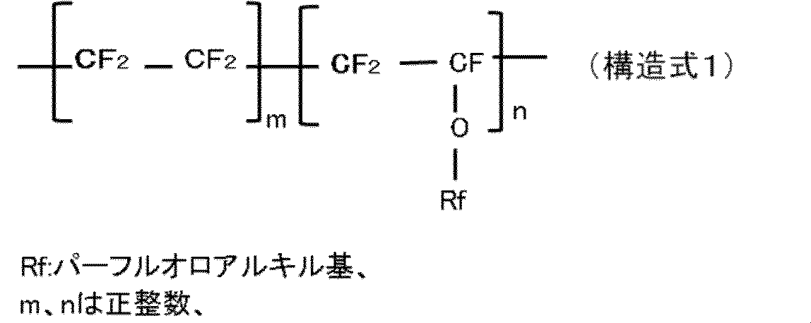
- a film of perfluoroalkoxyalkane (hereinafter referred to as "PFA”) represented by the following structural formula 1 is provided on the outermost surface of at least one of the outer wall surface of the rotating shaft and the inner wall surface of the seal housing First rotation mechanism).
- PFA of the present invention is a copolymer of tetrafluoroethylene and perfluoroalkylvinylether, which has a structure as shown in Structural Formula 1.
- Rf include an alkyl group having two or more fluorine atoms, such as a totally fluorinated alkyl group.
- the carbon number of Rf is not particularly limited, but is preferably 1 or more, preferably 2 or more, and usually 12 or less, preferably 6 or less.
- the weight average molecular weight of the PFA of the present invention is not particularly limited, but it is preferable to satisfy the melting point and density characteristics as described above.
- the film of the PFA is a film derived from remelting (a second rotation mechanism).
- a method of manufacturing a rotary mechanism of a gas exhaust pump comprising: a rotary shaft of a screw rotor and a seal housing rotatably mounting the rotary shaft. Prepare at least one of the rotary shaft on which the PFA coating film is provided and the seal housing on which the PFA coating film is provided on the inner wall surface, and expose the prepared member to a temperature atmosphere higher than the PFA melting temperature.
- At least the free surface area of the coating film is melted and then exposed to a temperature lower than the melting temperature of PFA to solidify at least a portion which becomes the free surface area, and then the melting temperature of PFA or the temperature exceeding the melting temperature of PFA
- exposing to an atmosphere at a temperature of at least a part of the free surface area and then lowering the temperature to a temperature sufficiently lower than the melting temperature of PFA characterized in that it comprises a step of increasing the smoothness of the free surface of the solid film made PFA (manufacturing method of the first rotary mechanism).
- a fourth aspect of the present invention is a gas exhaust pump including the rotation mechanism of the first or second aspect (first gas exhaust pump).
- the fifth aspect of the present invention is characterized in that the method for manufacturing the gas exhaust pump includes the steps included in the method for manufacturing the rotary mechanism of the third aspect (a first gas exhaust pump Production method).
- the sixth aspect of the present invention is characterized in that, in the method of manufacturing the gas exhaust pump, the rotary mechanism of the first or second aspect is used as an assembly part in the assembling step (a first gas Second manufacturing method of exhaust pump).
- the amount of use of the seal gas is much smaller than that of the conventional similar pump, and the rotation abnormality occurs even when operated at high speed continuously for a long time It is possible to maintain the expected turning performance without coming.
- the rotation mechanism according to the present invention is composed of a rotation shaft 105 and a seal housing 108.
- the rotating shaft 105 and the seal housing 108 are disposed with a predetermined gap 117 therebetween.
- At least one of the outer surface (outer wall surface 119) of the rotating shaft 105 and the inner surface (inner wall surface 118) of the seal housing 108 is provided with a PFA film represented by Structural Formula 1.
- FIG. 1 the example which provided the PFA film
- the PFA film 120 provided on at least one surface of the rotating shaft 105 and the seal housing 108 (both together referred to as "rotational mechanism member") is melted after coating PFA on the wall surface forming at least the gap 117 of the rotational mechanism member By forming through the process of and remelting, high smoothness is imparted to the free surface.
- the PFA of structural formula 1 adopted in the present invention is manufactured and sold by many companies. Among them, in the present invention, those having a melting point of 298 to 310 ° C. and a density of 2.12 to 2.17 are preferable. Also, when it is necessary to consider the use at high temperatures, it is desirable to select the highest continuous use temperature, preferably at least 260 ° C.
- the thermal conductivity be, for example, 0.25 W / m ⁇ k or more.
- the melt viscosity of PFA is an important factor in forming a film with high surface smoothness and no undulation. If the melt viscosity is too high, it will be difficult to obtain high surface smoothness and waviness is likely to occur.
- the melt viscosity of PFA is preferably 10 g / 10 min or more, more preferably 20 g / 10 min or more, in accordance with ASTM D3307.
- ASTM D3307 a somewhat high melt viscosity.
- AC-5539 for electrostatic coating polymer thick coating, powder
- Other AC series include AC-5600, ACX-21, ACX-31, ACX-31 WH, ACX-34, and ACX-41.
- AD-2CRE painted film thickness: 10 to 15 ⁇ m
- AW-5000 L painted film thickness: 30 to 40 ⁇ m
- AD-2CRE is recommended to be used after filtration of paint with a wire mesh of 100 to 150 mesh, and AW-5000L with a wire mesh of 60 to 80 mesh, respectively.
- the air spray conditions are a nozzle diameter of 1.0 mm ⁇ of a spray gun and an atomization pressure of 0.2 MPa.
- the coating conditions of AW-5000L preferably, the nozzle diameter of the spray gun is 1.0 to 1.2 mm ⁇ and the atomization pressure is 0.2 to 0.4 MPa as air spray conditions.
- primers for water system ED-1939D21L, EK-1908S21L, EK-1909S21L, EK-1959S21L, EK-1983S21L, EK-1208M1L, EK-1209BKEL, EK-1209M10L, EK-1283S1L, TC as a solvent-based primer -1509 M1, TC-1559 M2, TC-11000, and the like.
- the coating conditions of the primer coating are, for example, the nozzle diameter of the spray gun 1.0 to 1.2 mm ⁇ , the atomization pressure 0.2 to 0.4 MPa, or the nozzle diameter of the spray gun 1.0 to 1.5 mm ⁇ , atomization
- the pressure is 0.2 to 0.3 MPa. Drying is performed, for example, at a temperature of 80 to 90 ° C. and for a time of 10 to 15 minutes.
- MP-102 micro powder, for top coat
- MP-103 micro powder, for top coat
- MP-300 fluorinated powder, for top coat
- MP-310 fluorinated powder, for top coat
- MP-630 conductive powder
- MP-642 conductive powder
- MP-620 high thermal conductivity
- MP-621 thermal conductivity
- MP-623 high thermal conductivity
- MP-501 for articles that can not be electrostatically coated due to complex shapes
- MP-502 complex For articles that can not be electrostatically coated due to their shape
- SL-800BK with carbon filler
- SL-800LT with glass filler
- MP-103, MP-300 and MP-310 are preferable in the present invention because the obtained film is excellent in planar smoothness.
- MP-310 is particularly preferable because spherulite control is excellent at about 5 ⁇ m in terms of micro and uniformity.
- SL-800BK is preferable in the present invention in terms of heat dissipation because it has good heat conductivity and excellent heat dissipation.
- MP-630, 642 conductive micropowder
- PFA material is also used as a preferred PFA material in the present invention in terms of good thermal conductivity and excellent heat dissipation.
- Rf in structural formula 1 is particularly preferably PFA of “—CF 2 CF 2 CF 3”, and the molecular weight: several hundred thousand to one million and the melting point: 300
- the viscosity is ⁇ 310 ° C
- the viscosity is 104-105 poise (380 ° C)
- the maximum continuous use temperature is 260 ° C.
- PFA primer PL-902 series sold as general aqueous general purpose primers and PFA primers PL-910 series sold as primers excellent in heat resistance and corrosion resistance are preferable. Specifically, it is sold under the brand names of PL-902YL, PL-902BN, PL-902AL, PL-910YL, PL-910BN, PL-910AL, and PL-914AL.
- NK-108 lubricity, standard film thickness 50 ⁇ m, heat resistant temperature 260 ° C
- NK-372, 379 lubrication, antistatic, standard film thickness 100, 300 ⁇ m, heat resistant temperature 260 ° C
- NK-013, 013 C abrasion resistant Standard film thickness 300 ⁇ m, heat resistant temperature 150 ° C.
- NF-015 standard film thickness 50 ⁇ m
- NF-015 EC standard film thickness 40 ⁇ m, antistatic
- NF-020AC standard film thickness 600 ⁇ m, antistatic
- a metal base material for a member to be added which has good heat conductivity and is suitable for processing, such as stainless steel, aluminum metal such as aluminum or aluminum alloy Be done.
- the rotary shaft and the seal housing are engaged via the angular bearing so that the rotary shaft can freely rotate, but when the high speed rotation is maintained for a long time, the rotary shaft and the angular roller Since frictional heat is generated between the bearings, it is desirable to select a substrate with good thermal conductivity in order to further enhance the heat dissipation effect of the rotary shaft and the seal housing.
- an aluminum-based metal As such a substrate, it is desirable to select an aluminum-based metal because it is lightweight, but it is desirable to select a material that is as hard as possible and has a small thermal expansion coefficient.
- a base material made of aluminum an aluminum alloy containing other metals besides pure aluminum is employed in the present invention.
- the aluminum alloy in the present invention is made of a metal whose main component is aluminum.
- the metal containing aluminum as its main component is a metal containing usually 50% by mass or more of aluminum, preferably the metal contains 80% by mass or more of aluminum, more preferably 90% by mass or more of aluminum, and still more preferably 94% by mass. It is desirable to include% or more.
- a preferable metal contained in the aluminum alloy at least one metal selected from the group consisting of magnesium, titanium and zirconium can be mentioned. Among them, magnesium is particularly preferable because it has an advantage of improving the strength of the aluminum alloy.
- the aluminum alloy may be a metal mainly composed of high purity aluminum in which the content of a specific element (iron, copper, manganese, zinc, chromium) is suppressed. It is preferable that the sum total of content of these specific elements is 1.0 mass% or less, More preferably, it is 0.5 mass% or less, More preferably, it is 0.3 mass% or less.
- a specific element iron, copper, manganese, zinc, chromium
- the aluminum alloy containing high purity aluminum as a main component may contain one or more kinds of other metals capable of forming an alloy with aluminum, if necessary.
- Such metal is not particularly limited as long as it is other than the above-mentioned specific element, but preferable metals include at least one or more metals selected from the group consisting of magnesium, titanium and zirconium.
- magnesium is particularly preferable because it has an advantage of improving the strength of the aluminum alloy.
- the magnesium concentration is not particularly limited as long as it can form an alloy with aluminum, but in order to bring about a sufficient improvement in strength, it is usually at least 0.5 mass%, preferably at least 1.0 mass%, more preferably Preferably, it is 1.5% by mass or more.
- the content is preferably 6.5% by mass or less, more preferably 5.0% by mass, still more preferably 4.5% by mass or less, and most preferably 3% by mass It is below.
- the aluminum alloy in the present invention may contain other metal components as a crystal modifier in addition to the above-mentioned metals.
- the material is not particularly limited as long as it has a sufficient effect on crystal control, but preferably zirconium or the like is used.
- the individual content of the metal other than aluminum which is positively contained in the aluminum alloy is usually 0.01% by mass or more, preferably 0, with respect to the entire aluminum alloy.
- the content is preferably 0.05% by mass or more, more preferably 0.1% by mass or more.
- the lower limit of this content is necessary to sufficiently develop the characteristics of the contained metal.
- the content is usually 20% by mass or less, preferably 10% by mass or less, more preferably 6% by mass or less, particularly preferably 4.5% by mass or less, and most preferably 3% by mass or less. This upper limit is necessary to maintain a uniform solid solution of aluminum and other metal components other than aluminum and maintain good material properties.
- the base material (also referred to as "workpiece") to be processed as a rotating mechanism member for a screw pump according to the present invention is provided with a PFA film for forming a wall surface which constitutes a passage of seal gas. It is preferable that the PFA film mounting surface be smoothed by means of electrolytic polishing, mechanical polishing, or both, to give a desired smoothness.
- the smoothness of the polishing surface at this stage is preferably not more than the average particle diameter of the PFA powder.
- the PFA film is not provided directly on the polished surface of the base material, this may not be the case.
- a film (referred to as an "underlying film") made of Al 2 O 3 or Ni or NiF 2 is in advance base material. It is desirable to provide it on the PFA membrane installation surface of If a film made of Ni or NiF 2 is provided in advance on the PFA film mounting surface of the base material, the effect of suppressing the thermal decomposition of PFA is large when melting or remelting the PFA film provided thereon Therefore, a film of good quality can be obtained even if the melting temperature is set higher than other base materials. Furthermore, since the Ni film has high corrosion resistance and high adhesion to the PFA film, it is preferable as a base film for the PFA film.
- Ni film on the PFA film setting surface of the substrate for example, electroless nickel plating, plasma sputtering in which Ni is sputtered to form a film is adopted, and in addition, Ni MOCVD using an organic complex can also be employed.
- the plating solution contains a reducing agent
- P (phosphorus) or B (boron) can be contained in the obtained Ni film depending on the reducing agent used.
- hypophosphite is used as the reducing agent
- P (phosphorus) can be contained in the obtained Ni film
- DMAB dimethylamine borane
- the hardness of the film can be increased and the electric resistance of the film can be reduced as compared to the case where P (phosphorus) is contained in the Ni film. You can use it according to your needs.
- the use of hydrazine as the reductant is advantageous as it does not generate hydrogen gas during the reaction as in the case of hypophosphorous acid or DMAB.
- the amount of P (phosphorus) contained in the Ni film can be appropriately determined depending on the application of the reaction vessel, but the chemical composition is preferably Ni: 83 to 98%, P: 2 to 15%, others: It is desirable to set it to 0 to 2%. In the case of B (boron), it is desirable that Ni: 97 to 99.7%, B: 0.3 to 3%, others: 0 to 2.7% in chemical composition.
- the electroless nickel plating may be carried out by itself because it is commercially available or can be prepared by itself, but it may be processed by a third party based on the specification. The objective is achieved.
- Commercially available electroless nickel plating solutions are manufactured or sold by, for example, Tool System Co., Ltd., World Metal Co., Ltd., Metal Processing Technology Research Institute, Inc., Okuno Pharmaceutical Co., Ltd., Uemura Kogyo Co., Ltd., and the like.
- the free surface of the Ni film provided on the PFA film mounting surface of the workpiece may be fluorinated.
- a base material provided with a Ni film on the surface is set in a vacuum vessel, and after reaching a predetermined degree of vacuum, F 2 gas is supplied into the vacuum vessel to make the surface of the Ni film F 2 gas You can expose it to In this case, the entire Ni film can be made NiF 2 film by controlling the exposure time to F 2 gas, or a two-layer structure can be made with the lower part being a Ni film and the upper part being a NiF 2 film. .
- the distribution of F atoms in the thickness direction of the film can be changed.
- the adhesion with the substrate and the adhesion with the PFA film can be further strengthened.
- P (phosphorus) or B (boron) having the above-mentioned chemical composition is applied to the NiF 2 film obtained by fluorinating the Ni film containing P (phosphorus) or B (boron) as described above. Needless to say, it is contained in the film.
- a Ni film and a Ni-based film are provided as a base film, after electroless plating, annealing is performed at a desired temperature in an atmosphere such as a rare gas or a nitrogen gas for a desired time to obtain a film as a substrate.
- This method is a preferred primer post-treatment method in the present invention because adhesion and hardness can be greatly enhanced.
- annealing it is preferable to perform annealing for about 1 hour, for example, in a temperature range of 260 to 350 ° C. in a nitrogen atmosphere, for example.
- An anodic oxidation method capable of forming a nonporous Al 2 O 3 film is preferably employed to provide an Al 2 O 3 film as a base film on the PFA film mounting surface of a workpiece made of aluminum.
- the film formed by the anodic oxidation method is formed by an anodic oxidation method described later on at least the PFA film mounting surface of the workpiece.
- the Al 2 O 3 anodic oxide film is a film made of an oxide of a metal mainly composed of aluminum, and can easily be formed to a thickness of 10 nm or more. Since this film is a passive film, it exhibits high performance as a protective film when formed on the inner surface of the aluminum reaction container main body.
- the film thickness of the Al 2 O 3 anodic oxide film is preferably 100 ⁇ m or less. If the film thickness is large, it is easy to crack and release outgassing. Therefore, the film thickness of the Al 2 O 3 anodic oxide film is more preferably 10 ⁇ m or less, still more preferably 1 ⁇ m or less, still more preferably 0.8 ⁇ m or less, particularly preferably 0.6 ⁇ m or less. The lower limit of the film thickness is preferably 10 nm or more. If the film thickness is too thin beyond this range, sufficient corrosion resistance can not be obtained. The film thickness of the Al 2 O 3 anodic oxide film is more preferably 20 nm or more, still more preferably 30 nm or more.
- the nonporous Al 2 O 3 film according to the present invention is excellent in corrosion resistance even though it is a thin film with respect to a porous Al 2 O 3 film having a porous structure conventionally used, and it has fine pores and pores. There is an advantage that it does not adsorb or hardly adsorbs water and the like because it has none or almost no (substantially no).
- the Al 2 O 3 anodic oxide film can be obtained by anodizing the inner surface of the aluminum container body or structure using a chemical solution having a pH of 4 to 10. According to this method, there is an advantage that a dense and non-porous anodic oxide film can be easily obtained.
- this method has the advantage of being able to form a dense and smooth anodic oxide film because it has the function of repairing defects caused by the non-uniformity of the metal surface.
- the lower limit of the pH value of the chemical conversion solution is 4 or more as described above, preferably 5 or more, more preferably 6 or more.
- the upper limit of the pH value of the chemical conversion solution is usually 10 or less, preferably 9 or less, more preferably 8 or less.
- the pH value should be neutral or near neutral, or be as neutral as possible. Is desirable.
- the chemical conversion solution be in the range of pH 4 to 10 in order to buffer the concentration fluctuation of various substances during anodic oxidation to keep the pH within the predetermined range (buffering action). Therefore, it is desirable to include a compound such as an acid or a salt exhibiting a buffer action (hereinafter sometimes referred to as "compound (A)").
- the type of such a compound is not particularly limited, but is preferably at least one selected from the group consisting of oxalic acid, phosphoric acid and organic carboxylic acids and salts thereof, from the viewpoint of high solubility in a chemical conversion solution and good dissolution stability. is there. More preferably, it is an organic carboxylic acid or a salt thereof having little residual of boron and phosphorus in the anodic oxide film.
- the concentration of these compounds (A) may be appropriately selected according to the purpose, but is usually 0.01% by mass or more, preferably 0.1% by mass or more, and more preferably 1% by mass, based on the whole of the chemical conversion solution. And above. It is desirable to increase the conductivity to sufficiently form the anodic oxide film. However, the content is usually 30% by mass or less, preferably 15% by mass or less, more preferably 10% by mass or less. In order to keep the performance of the anodic oxide film high and to reduce the cost, 10% by mass or less is desirable.
- the chemical conversion solution in the present invention preferably contains a non-aqueous solvent.
- a chemical conversion solution containing a non-aqueous solvent When a chemical conversion solution containing a non-aqueous solvent is used, the time required for constant current chemical formation can be shortened compared to an aqueous solution-based chemical conversion solution, and there is an advantage that processing can be performed with high throughput.
- OH ions generated by the electrolysis of water etch the anodic oxide film to make it porous, so a main solvent with a small dielectric constant that can suppress the electrolysis of water is used. It is preferred to use.
- non-aqueous solvent is not particularly limited as long as it can be anodically oxidized well and has sufficient solubility in a solute, but a solvent having one or more alcoholic hydroxyl groups and / or one or more phenolic hydroxyl groups Or aprotic organic solvents are preferred. Among them, a solvent having an alcoholic hydroxyl group is preferable in terms of storage stability.
- Examples of the compound having an alcoholic hydroxyl group include monohydric alcohols such as methanol, ethanol, propanol, isopropanol, 1-butanol, 2-ethyl-1-hexanol and cyclohexanol; ethylene glycol, propylene glycol, butane-1,4 -Dihydric alcohols such as diol, diethylene glycol, triethylene glycol and tetraethylene glycol; and polyhydric alcohols having three or more valences such as glycerin and pentaerythritol can be used.
- numerator can also be used.
- those having two or more alcoholic hydroxyl groups are preferable in terms of water miscibility and vapor pressure, dihydric alcohols and trihydric alcohols are more preferable, and ethylene glycol, propylene glycol and diethylene glycol are particularly preferable.
- These compounds having an alcoholic hydroxyl group and / or a phenolic hydroxyl group may further have other functional groups in the molecule.
- a solvent having an alkoxy group together with an alcoholic hydroxyl group can also be used, such as methyl cellosolve and cellosolve.
- aprotic organic solvent either a polar solvent or a nonpolar solvent may be used.
- the polar solvent is not particularly limited, but, for example, cyclic carboxylic acid esters such as ⁇ -butyrolactone, ⁇ -valerolactone and ⁇ -valerolactone; linear carboxylic acid esters such as methyl acetate, ethyl acetate and methyl propionate Cyclic carbonates such as ethylene carbonate, propylene carbonate, butylene carbonate, vinylene carbonate; linear carbonates such as dimethyl carbonate, ethyl methyl carbonate, diethyl carbonate, N-methyl formamide, N-ethyl formamide, N, N- Amides such as dimethylformamide, N, N-diethylformamide, N-methylacetamide, N, N-dimethylacetamide, N-methylpyrrolidone, acetonitrile, glutaronitrile, adiponitrile, methoxyaceto Ni
- the non-aqueous solvent is contained in a proportion of usually 10% by mass or more, preferably 30% by mass or more, more preferably 50% by mass or more, particularly preferably 55% by mass or more based on the whole chemical conversion solution, usually 95% by mass or less Preferably it is 90 mass% or less, Especially preferably, it is contained in the ratio of 85 mass% or less.
- the content thereof is usually 1% by mass or more, preferably 5% by mass or more, more preferably 10% by mass as the lower limit based on the whole of the chemical conversion solution.
- the upper limit is usually 85% by mass or less, preferably 50% by mass or less, and particularly preferably 40% by mass or less.
- the lower limit value of the ratio of water to the non-aqueous solvent is preferably 1% by mass or more, preferably 5% by mass or more, more preferably 7% by mass or more, particularly preferably 10% by mass or more.
- the upper limit is usually 90% by mass or less, preferably 60% by mass or less, more preferably 50% by mass or less, and particularly preferably 40% by mass or less.
- the chemical conversion solution may contain other additives as needed.
- it may contain an additive for improving the film forming property and film characteristics of the anodic oxide film.
- the additive is not particularly limited, and can be used by adding one or more substances selected from additives used in known chemical conversion solutions and other substances. At this time, the addition amount of the additive is not particularly limited, and may be an appropriate amount in consideration of the effects, cost and the like.
- the electrolytic method for anodic oxidation is not particularly limited.
- the current waveform for example, in addition to direct current, a pulse method in which the applied voltage is periodically interrupted, PR method in which the polarity is reversed, other alternating current or AC / DC superimposition, incomplete rectification, modulation current such as triangular wave can be used. But preferably using a direct current.
- the control method of the current and voltage of the anodic oxidation is not particularly limited, and the conditions under which the oxide film is formed on the inner surface of the aluminum alloy container main body can be appropriately combined.
- the current density is usually 0.001 mA / cm 2 or more, preferably 0.01 mA / cm 2 or more.
- the current density is usually 100 mA / cm 2 or less, preferably 10 mA / cm 2 or less.
- the formation voltage Vf is usually 3 V or more, preferably 10 V or more, more preferably 20 V or more. Since the obtained oxide film thickness is related to the formation voltage Vf, it is preferable to apply the above voltage or more in order to give the oxide film a certain thickness. However, the voltage is usually 1000 V or less, preferably 700 V or less, and more preferably 500 V or less. Since the obtained oxide film has high insulation, in order to form a good quality oxide film without causing high dielectric breakdown, it is preferable to carry out below the above-mentioned voltage.
- an alternating current with a constant peak current value may be used until the formation voltage, and a method of switching to the direct current voltage and holding for a predetermined time when the formation voltage is reached may be used.
- the temperature at the time of anodic oxidation is a temperature range in which the chemical conversion solution stably exists as a liquid. Usually, it is ⁇ 20 ° C. or higher, preferably 5 ° C. or higher, and more preferably 10 ° C. or higher. It is preferable to process above the said temperature in consideration of production, energy efficiency, etc. at the time of anodic oxidation. However, it is usually 150 ° C. or less, preferably 100 ° C. or less, and more preferably 80 ° C. or less. It is preferable to process below the said temperature, in order to maintain the composition of a chemical conversion liquid and to perform uniform anodic oxidation.
- the anodic oxidation is performed in the first step of arranging the inner surface of the aluminum reaction container main body or its structure and the counter electrode (for example, platinum) in the chemical conversion solution, the aluminum reaction container main body or its structure And a second step of applying a negative current to the electrode and supplying a constant current for a predetermined time, and a predetermined voltage for a predetermined voltage between the aluminum reaction container main body or its structure and the electrode It is preferable to include the third step of applying.
- the predetermined time of the second step is until the voltage between the aluminum reaction container main body or its structure and the predetermined electrode reaches a predetermined value (for example, 200 V when ethylene glycol is used). It is preferable to set it as
- the predetermined time of the third step is set until the current between the aluminum alloy container main body or the structure thereof and a predetermined electrode reaches a predetermined value.
- the current value decreases rapidly when the voltage reaches the above predetermined value, and then gradually decreases with time (referred to as “residual current”), but for example, it becomes 24 or less when the constant voltage processing ends below the predetermined current value. It takes time.
- residual current the film quality of the obtained Al 2 O 3 anodic oxide film becomes equivalent to that of the heat-treated one.
- the less the residual current the better the film quality of the Al 2 O 3 anodic oxide film.
- the constant voltage treatment in order to improve the productivity, it is desirable to stop the constant voltage treatment for an appropriate time and to apply a heat treatment (annealing) in the next step.
- the heat treatment is preferably performed at 150 ° C. or higher, more preferably at about 300 ° C. for 0.5 to 1 hour.
- constant voltage treatment may be continued, and if long, heat treatment may be switched.
- a current of usually 0.01 to 100 mA, preferably 0.1 to 10 mA, and more preferably 0.5 to 2 mA per square cm.
- the voltage is set to a voltage such that the formation liquid does not cause electrolysis.
- the nonporous Al 2 O 3 anodic oxide film formed during the chemical conversion treatment has an amorphous structure as a whole. It is considered that there are almost no grain boundaries such as crystals. Further, by adding a compound having a buffer action or using a non-aqueous solvent as a solvent, a trace amount of carbon component is taken into the anodic oxide film, and the bonding strength of Al-O is weakened. Thereby, it is presumed that the amorphous structure of the whole film is stabilized.
- the Al 2 O 3 anodic oxide film produced as described above be subjected to heat treatment for the purpose of completely removing water in the film.
- the anodic oxide film of Al formed on an aluminum alloy base material mainly containing high purity aluminum containing substantially no specific element has high thermal stability, and it is difficult to form voids, gas pools and the like. There is. Therefore, even when annealing is performed at about 300 ° C. or more, almost no voids or seams are generated in the anodic oxide film of Al, so that the elution of aluminum into the reaction solution due to the generation of particles and the exposure of aluminum can be suppressed.
- the temperature of the heat treatment is not particularly limited, but is usually 100 ° C. or higher, preferably 200 ° C. or higher, and more preferably 250 ° C. or higher.
- the temperature is 600 ° C. or less, preferably 550 ° C. or less, and more preferably 500 ° C. or less. It is desirable to carry out the treatment at the above temperature in order to maintain the amorphous structure of the Al 2 O 3 anodic oxide film and maintain the surface flatness.
- the heat treatment time is not particularly limited, but may be appropriately set in consideration of surface roughness due to heat treatment, productivity, etc., but is usually 1 minute or more, preferably 5 minutes or more, particularly preferably 15 It is more than a minute.
- it is preferable to process for the above-mentioned time or more. However, it is usually 180 minutes or less, preferably 120 minutes or less, more preferably 60 minutes or less. It is desirable to process within the above time to maintain the Al 2 O 3 anodic oxide film structure and surface flatness.
- the gas atmosphere in the furnace at the time of the annealing treatment is not particularly limited, but usually, nitrogen, oxygen or a mixed gas of these, etc. can be used appropriately. Among them, an atmosphere having an oxygen concentration of 18 vol% or more is preferable, a condition of 20 vol% or more is more preferable, and a condition having an oxygen concentration of 100 vol% is the most preferable.
- the thickness of the undercoating film is such that the smoothness of the surface on which the PFA film is provided can be sufficiently secured as desired, the smoothness of the PFA film mounting surface of the base material, and the average particle diameter of the PFA powder used Or, in consideration of the average particle diameter of the PFA particles dispersed in the PFA paint, etc., it is selected according to the need.
- it is preferably 0.1 to 30 ⁇ m, more preferably 1 to 20 ⁇ m, still more preferably 2 to 15 ⁇ m.
- PFA film formation surface In order to provide the PFA film on the PFA film installation surface of the workpiece or on the base film surface (both are collectively referred to as “PFA film formation surface”), it is described in the later described experiments 1, 2 and examples. However, it is preferable to do as follows.
- PFA film When forming a PFA film, there are some PFA prepared in the form of fine powder for electrostatic coating and those in the same liquid as common paints. In the present invention, it is preferable to use a fine powder of electrostatic coating for easy coating with uniform thickness even if the shape of the workpiece is somewhat complicated asperity.
- a coating method in the case of a liquid paint like the general paint, it is desirable to coat by spray coating, but depending on the substrate, it is painted by dip coating, dip spin coating, roll coating, and spin flow coating Those are also adopted appropriately. In addition, it is desirable that the powder coating be coated by electrostatic powder coating or electrostatic flow immersion.
- the PFA paint coated in this way is baked onto the PFA film-formed surface of the workpiece, but at that time, the PFA coating is given a process of melting and remelting, and finally the PFA with desired smoothness performance. A coating is obtained.
- the desired thickness can be obtained by repeatedly performing “(7) Top coat (PFA) coating ⁇ (8) preliminary drying ⁇ (9) primary baking (melting)” in the above process.
- the top coat layer can be formed.
- the coating thickness per one time is the form of PFA (powder or paint), the viscosity at the time of melt processing, the dispersion concentration and particle size of PFA in the case of paint, the particle size of powder in the case of powder, etc. It is decided appropriately by
- the thickness is preferably 1 to 100 ⁇ m.
- the primary firing temperature in the initial and intermediate coating is set as the intermediate primary firing temperature
- the primary firing temperature in the final coating is set as the final primary firing temperature.
- the intermediate primary firing temperature and the final primary firing temperature may be set to the same temperature, but preferably, the intermediate primary firing temperature is set lower than the final primary firing temperature It is desirable to
- the processing of (3), (5) and (6) may be omitted in some cases. For example, if adhesion is sufficient between the surface of the workpiece and the topcoat surface even if the topcoat is provided directly on the surface of the workpiece, the processing of (3), (5), (6) Can be omitted, and if the substrate and the top coat are strongly adhered by the primer coating, the processing of (3) can be omitted.
- the primary firing temperature and the firing time in the present invention are important factors for obtaining sufficient smoothness in the secondary firing to achieve the object of the present invention, and the PFA and the metal workpiece to be used, It can be appropriately determined according to the specification of the primer to be adopted as needed.
- the temperature and time of the primary firing are the impurities (low molecular weight components, non-fluorinated terminal groups) contained in the PFA material (available as powder or paint) by primary firing from the coated PFA film. It is desirable that the temperature and time be sufficient to discharge the components having the composition, products in the process of synthesis, additives such as surfactants, etc. out of the membrane.
- the upper limit of the primary firing temperature is a temperature at which PFA having a molecular weight necessary to form a PFA film giving high smoothness does not decompose (referred to as “PFA decomposition temperature”) or a temperature slightly higher than its decomposition temperature It is desirable to write “Th”. Th is determined in relation to the time for holding the PFA coating film at that temperature in the primary firing.
- the Th in the present invention is preferably set to 30 to 70 ° C. higher than the melting point of PFA used. If the set temperature is too low, sufficient smoothness may not be obtained in the secondary firing, and if too high, PFA decomposition may be promoted. More preferably, the temperature is 35 to 60 ° C., and even more preferably 40 to 50 ° C.
- the primary firing time in the present invention comprises a time for raising the temperature to the primary firing temperature (primary firing temperature rising time) and a time for maintaining the primary firing temperature (primary firing temperature holding time).
- the temperature rising speed is controlled by the control device so that the heat is transmitted to any part of the PFA coating film and the PFA coating film is uniformly fired.
- the primary firing temperature holding time is the time to ensure that the entire free surface of the PFA coating film is melted as uniformly as possible so that the local non-uniformity can not be seen visually.
- the primary firing temperature holding time depends on the thickness and size of the PFA coating film, it can be appropriately determined according to the thickness and size of the PFA coating film, but preferably 10 It is desirable that the time is set to 50 minutes, more preferably 15 to 40 minutes.
- the firing temperature in the primary firing is The temperature rising speed to the firing temperature and the holding time at the firing temperature are appropriately determined in consideration of the thickness and the size of the base material, PAF and PFA coating film.
- the impurities contained in the PFA material are decomposed and removed from the PFA film. It is thought that the smoothness of the PFA film subjected to the secondary firing is significantly improved by removing the extra impurities from the PFA film in the primary firing.
- the primary firing is performed in a gas atmosphere in which oxygen is mixed with a rare gas, such as a 20 vol% O 2 / Ar gas atmosphere.
- the present invention is not limited to this, and oxygen gas alone may be used, or a nitrogen / oxygen mixed gas may be used. Instead of nitrogen, a mixed gas of NO and NO 2 mixed with oxygen may be used. NO and NO 2 may be used alone. Instead of oxygen gas, ozone can also be used.
- the sample is cooled to a temperature (referred to as "Tl") below the melting point of the PFA used and solidified (primary cooling and solidification).
- Tl a temperature below the melting point of the PFA used and solidified (primary cooling and solidification).
- the temperature Tl below the melting point at this time is preferably lower than the melting point of PFA used, preferably 5 to 60 ° C, more preferably 10 to 50 ° C, and still more preferably 20 to 50 ° C.
- the primary firing temperature is appropriately selected according to the above range with respect to the lowest temperature in the temperature range of the range.
- the temperature rise speed to raise the temperature from the above melting point (primary cooling and solidification temperature) Tl to the secondary firing temperature and the holding time at the secondary firing temperature are determined by freeing the PFA film obtained by secondary cooling to room temperature It is set such that the smoothness of the surface is sufficiently ensured.
- the secondary firing temperature is a temperature for remelting the PFA film once solidified through the primary firing treatment, and solidified through the temperature lowering process to the room temperature where the PFA coating film subjected to the primary firing treatment is applied next Temperature which promotes smoothing at the time of
- the secondary firing is preferably performed at the melting point of PFA used or at a temperature within 15 ° C. higher than the melting point. More preferably, it is carried out at a temperature slightly different from the melting point of PFA used or the melting point around it.
- Rf in Structural Formula 1 is “—CF 2 CF 2 CF 3 ” (melting point is 310 ° C.)
- PFA fine powder is electrostatically applied to a PFA film-forming surface of a workpiece. And heat to 345 ° C. at a programmed heating rate, and hold this 345 ° C. state for 30 minutes (melting step).
- This melting step is performed in a 20 vol% O 2 / Ar gas atmosphere.
- the atmosphere is switched to a 100 vol% argon atmosphere, the temperature is lowered at a predetermined rate to 280 ° C., and when the temperature reaches 280 ° C., the temperature is maintained for 30 minutes. Subsequently, it is heated again to 310 ° C. at a predetermined rate (re-melting step), and this temperature is maintained for 30 minutes. After holding for 30 minutes, the temperature is lowered to room temperature by stopping heating and leaving it to stand naturally. Through such a process, a PFA film can be formed in which the free surface has extremely good smoothness.
- a temperature in the range of 295 ° C. to 315 ° C. can be selected as the temperature of the remelting step.
- the smoothness is best at a temperature slightly different from the melting point at or around 310 ° C.
- the temperature is in the range of 305 ° C. to 315 ° C. It is desirable to remelt at temperature.
- the mirror-finished surface of the substrate 1 was subjected to the following treatment, and then immersed in a bath of the electroless plating solution (A) to form a Ni film.
- the base material 1 was immersed in a commercially available degreaser (OPC-370 Condiclean M (trade name), Okuno Seiyaku Kogyo Co., Ltd.) at 60 ° C. for 5 minutes. Then, it was pulled up from the degreasing agent, and the mirror-finished surface was sufficiently washed with semiconductor ultrapure water. Thereafter, it was immersed for 5 minutes at 25 ° C. in a commercially available catalyst imparting agent (OPC-80 Catalyst (trademark), manufactured by Okuno Pharmaceutical Co., Ltd.). Then, it was pulled up from the catalyst-applying agent, and the mirror-finished surface was sufficiently washed with semiconductor ultrapure water.
- OPC-370 Condiclean M trade name
- the substrate 1 thus treated was immersed in the electroless plating solution (A) for 70 minutes. Next, it was pulled up from the electroless plating solution (A) and thoroughly washed with semiconductor ultrapure water. As a result of visual observation, the Ni film was uniformly formed on the entire mirror-finished surface, and the free surface was extremely smooth when touched with a finger.
- a precoat material (primer) is applied under the following conditions on the surface of the Ni film (free surface of Ni film) of the substrate 1 subjected to such treatment and the surface (mirror surface processed surface) on which the smoothness of the substrate 2 is measured. Then let dry.
- Precoat material EK-1908S21L (manufactured by Daikin Industries, Ltd.) Coating conditions: Nozzle diameter of spray gun ⁇ 1.2 mm ⁇ Atomization pressure ........... 0.3 MPa Drying conditions: 85 ° C, 15 minutes
- the substrate is accommodated in an infrared heating furnace and made of quartz In a container (quartz container).
- Top coat material AC-5600 (made by Daikin Industries, Ltd.)
- Electrostatic coating device made by Lansburg Co., Ltd.
- Hand gun Across REA 90 / L
- High pressure controller-9040 Number of times of recoating .... 3 times Coating amount per one ... 120 ⁇ 10 ⁇ m
- Intermediate firing between coatings ⁇ approximately 340 ° C, 15 minutes
- the infrared heating furnace used in this experiment always used 100% argon at a flow rate of 1 l / min inside the quartz container installed even when not used Maintain the internal cleanliness.
- thermocouple is attached to the outer periphery of the quartz vessel, and the temperature controller controls the output of the infrared light source so that the temperature is programmed based on the temperature information from the thermocouple.
- the quartz vessel is provided with a gas pipe for introducing a gas from the outside of the furnace, and for example, the furnace is introduced with a gas such as 100 vol% argon or 20 vol% oxygen mixed into the furnace.
- a gas such as 100 vol% argon or 20 vol% oxygen mixed into the furnace.
- the structure is such that the inside can be adjusted to the desired atmosphere.
- the gas was switched to an Ar 100 vol% gas, the gas was flowed at a flow rate of 5 l / min for 10 minutes, and the temperature of the quartz vessel was brought to 280 ° C. This state was maintained for 30 minutes. Visual observation of the PFA-treated surfaces of the substrates 1 and 2 revealed surface irregularities.
- the flow rate of Ar 100 vol% gas was changed to 1 l / min, and the temperature was raised from 280 ° C. to 310 ° C. in 6 minutes. When the temperature reached 310 ° C., the output of the infrared light source was controlled and held for 30 minutes. Thereafter, the quartz container was taken out, and the substrates 1 and 2 were housed in a desiccator and naturally cooled.
- the substrates 1 and 2 were naturally cooled to room temperature and then set in a surface roughness measuring device to measure the smoothness of the PFA surface.
- the PFA film on the substrate 1 will be referred to as Sample 1-1
- the PFA film on the substrate 2 as Sample 1-2.
- the free surface of the PFA film of each sample was divided into 5 parallel portions (for convenience referred to as the X-axis direction) every 2 cm, and each divided surface was measured on a straight line from end to end of the sample.
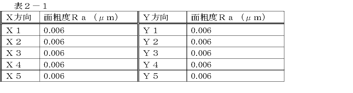
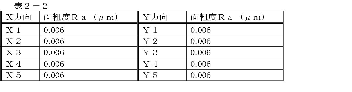
- Experiment 2 A sample for smoothness measurement by subjecting each substrate to a Ni treatment or PFA treatment in the same manner as in Experiment 1 except that the plate-like substrate in Experiment 1 was replaced by a semi-cylindrical substrate having a cylindrical concave surface as the inner surface. Obtained 2-1 (Ni-treated) and 2-2 (Ni-treated). The smoothness was measured in the same manner as in Experiment 1 for these. The results are shown in Table 2-1 and Table 2-2.
- Experiment 3 Experiment and smoothness measurement of presence or absence of remelting of PFA film Prepare two plate-like SUS substrates (SUS316L-EP: 2 cm ⁇ 5 cm) which are mirror-polished and prepare the same as in Experiment 1, and prepare the same on the mirror-polished surface of the SUS substrate. A Ni film was provided. When the surface roughness of the mirror-polished surface and the Ni film surface of the two SUS substrates was measured in the same manner as in Experiment 1, substantially the same results as in Experiment 1 were obtained.
- a SUA substrate in which PFA powder was electrostatically applied to a quartz crucible was placed in a quartz container and placed in a quartz container, and firing was performed according to the following procedure.
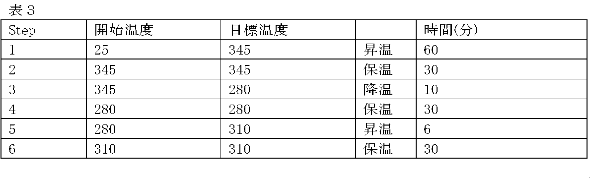
- (1) Flow 20% O 2 / Ar at a flow rate of 1 l / min and raise the temperature from room temperature to 345 ° C. in 1 hour.
- (2) The atmosphere is maintained at 345 ° C. for 30 minutes.
- (3) Flow 100% of Ar at a flow rate of 5 l / min and lower to 280 ° C. in 10 minutes.
- the sample 3-2 is moved to the unheated position so that the subsequent heating history (remelting) does not occur.
- the temperature program is shown below.
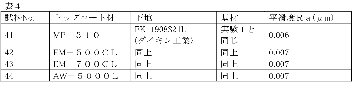
- Experiment 4 A PFA film is provided on the mirror-polished surface of the plate-like SUS substrate in the same manner as in Experiment 1 except that the topcoat material is changed to the conditions described in Table 4. The smoothness was measured. The results are shown in Table 4.
- Top coat material MP-310 Mitsubishi Chemical Company, Inc.
- EM-500CL Mitsubishi Chemical Company, Inc.
- EM-700CL Mitsubishi Chemical Company, Inc.
- AW-5000L Daikin Industries, Ltd.
- the rotating shaft 105 and the cylindrical seal housing 108 were produced as follows.
- a lubricating oil supply passage 109 was provided inside the rotary shaft 105.
- Several sets of rotating shafts and seal housings were prepared.
- SUS316L As a substrate, SUS316L was used.
- the cut surface was subjected to a cleaning treatment in the same manner as in Experiment 1 and then subjected to electropolishing to perform mirror finish.
- the electropolished rotating shaft and the seal housing were degreased and subjected to ultrapure water cleaning to clean the electropolished surface.
- the rotation shaft thus treated and the seal housing were mirror-finished (the rotation shaft is on the outer wall surface, and the seal housing is on the inner wall surface) I also prepared.
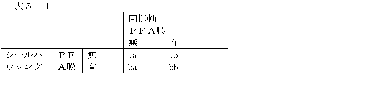
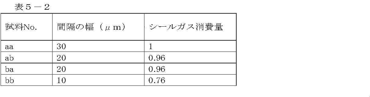
- the diameter of the rotating shaft, the inner diameter of the seal housing, and the PFA film thickness are such that the width of the gap between the outermost surface of the rotating shaft and the innermost surface of the seal housing when assembling the pump is the width shown in Table 5-2.
- the rotary shaft and the seal housing of each sample were processed.
- the rotary shaft and the seal housing prepared as above are paired, and four combinations as shown in Table 5-1 are made, and each is alternately incorporated into a screw pump, and the consumption of seal gas and continuous rotation I did a test.
- the results are shown in Table 5-2.
- the seal gas consumption is a relative value when the sample 11 is "1".
- Each of the pumps assembled by incorporating the rotary mechanism members (in this embodiment, the rotary shaft and the seal housing in this embodiment) of the samples aa, ab, ba and bb, respectively, in the initial stage even after continuous rotation for 10,000 hours. The smooth rotation of the state was maintained and no trouble occurred.
- the pump according to the present invention can significantly reduce the consumption of seal gas, the gas processing cost for recycling of the gas used in the processing process can be significantly reduced. In addition, it can greatly contribute to the reuse of valuable and expensive gases such as Kr and Xe, and is adopted as a high efficiency pump in a resource recycling type system.
- Screw pump 101 Female screw rotor 102 ⁇ Male screw rotor 103 ⁇ Screw tooth groove portion 104 ⁇ Screw male and female tooth groove meshing portion 105 ⁇ Rotating shaft 106 .... stator 107 ... angular bearings 108 ... seal housing 109 .... lubricating oil supply passage 110 ... base plate 111 .... lubricant 112 ...
Landscapes
- Engineering & Computer Science (AREA)
- Mechanical Engineering (AREA)
- General Engineering & Computer Science (AREA)
- Applications Or Details Of Rotary Compressors (AREA)
- Addition Polymer Or Copolymer, Post-Treatments, Or Chemical Modifications (AREA)
- Treatments Of Macromolecular Shaped Articles (AREA)
- Other Surface Treatments For Metallic Materials (AREA)
- Compressors, Vaccum Pumps And Other Relevant Systems (AREA)
Abstract
Description

AC-5539(静電塗装高分子厚塗り用、紛体)
AC系列としては、この他には、AC-5600、ACX-21、ACX-31、ACX-31WH、ACX-34、ACX-41が挙げられる。
EM-500CL(水性トップコート用)、EM-500GN(水性トップコート用)、EM-700CL(水性トップコート用)、EM-700GN(水性トップコート用)、EM-700GY(水性トップコート用)が挙げられ、これらは、複雑な形状のためで静電塗装が出来ない物品向きである。
NK-108(潤滑性、標準膜厚50μm、耐熱温度260℃)、NK-372,379(潤滑、帯電防止、標準膜厚100、300μm、耐熱温度260℃)、NK-013,013C(耐摩耗、標準膜厚300μm、耐熱温度150℃)が挙げられる。
NF-015(標準膜厚50μm)、NF-015EC(標準膜厚40μm、帯電防止)、NF-020AC(標準膜厚600μm、帯電防止)が挙げられる。
(1)金属基材(被塗装材)(電解研磨処理済)の準備 → (2)脱脂またはカラ焼き → (3)粗面化処理(ブラスト処理)又は/及び下地膜形成 ⇒ (4)清浄化⇒ (5)プライマー塗装 → (6)予備乾燥 → (7)トップコート(PFA)塗装 → (8)予備乾燥 → (9)一次焼成(溶融) → (10)一次冷却(使用するPFAの融点より低くする) → (11)二次焼成(再溶融) → (12)二次冷却(室温)
鏡面研磨処理した後、所定の洗浄処理を施した板状のSUS基材(SUS316LーEP:10x10mm2、厚さ2mm)を2枚(基材1,2)、用意した。これらの基材の鏡面加工面の表面平滑度を市販の面粗さ測定装置(Veeco社製 dektak 6M)で測定したところ、何れも面粗度Raは、0.006μmであった。
無電解メッキ液(A):硫酸ニッケル・・・・・・・26.3g/l
次亜リン酸ナトリウム・・・21.2g/l
クエン酸・・・・・・・・・25.0g/l
酢酸・・・・・・・・・・・12.5g/l
ロッセル塩・・・・・・・・16.0g/l
尿素・・・・・・・・・・・12.5g/l
pH・・・・・・・・・・・6.0
浴温・・・・・・・・・・・80℃
塗装条件:スプレーガンのノズル径・・・・・1.2mmφ
霧化圧力・・・・・・・・・・・・0.3MPa
乾燥条件:85℃、15分
静電塗装装置(ランズバーグ株式会社製):ハンドガン・・・・・REA90/L
高圧コントローラ・・9040
重ね塗り回数・・・・3回
一回当たりの塗装量・・・・120±10μm
塗装間での中間焼成・・・・・約340℃、15分
本実験で使用した赤外線加熱炉は、未使用時でも、石英容器の設置された内部に常に100%アルゴンを1l/minの流量で流して内部の清浄度を保っている。
測定結果が、表1に示される。

実験1における板状基材に代えて、内面が円筒凹面の半円筒基材にした以外は、実験1と同様にして、各基材をNi処理やPFA処理を施して平滑度測定用の試料2-1(Ni処理が施されている)、2-2(Ni処理が施されてない)を得た。これらについて、実験1と同様にして平滑度を測定した。その結果を表2-1及び表2-2に示す。
鏡面研磨がされている板状SUS基板(SUS316L―EP:2cm×5cm)を2枚(試料3-1,3-2)用意し、実験1と同様にしてSUS基板の鏡面研磨した面上にNi膜を設けた。実験1と同様に、2枚のSUS基板の鏡面研磨面とNi膜面の表面粗さを測定したところ、実験1と略同様の結果を得た。
委託先:日本フッソ工業株式会社
トップコート材:ACX-31(ダイキン工業株式会社製)
塗装法:静電塗装
PFA塗装厚:20μm
(1)20%O2/Arを1l/minの流量で流し室温から345℃まで1時間で昇温する。
(2)雰囲気はそのままで345℃を30分間保持する。
(3)Ar100%を5l/minの流量で流し10分で280℃に下げる。この段階で、試料3-2は、不加熱位置に移動させ、その後の加熱履歴(再溶融)が生じないようにする。
(4)雰囲気はそのままで280℃を30分間保持する
(5)雰囲気をAr100%、1l/minの流量に変えて6分で280℃から310℃まで昇温する。
(6)雰囲気はそのままで310℃を30分間保持する。
(7)加熱をOFFにし石英製の簀の子(試料3-1の)を不加熱位置に移動させて自然放冷させる。
試料3-1:Ra=0.061μm、PV=0.302μm
試料3-2:Ra=0.354μm、PV=2.141μm
トップコート材を変え、表4に記載の条件にした以外は、実験1と同様にして板状SUS基材の鏡面研磨面上にPFA膜を設けて、実験1と同様にしてPFA膜表面の平滑度を測定した。結果は、表4に示す。
トップコート材
MP-310(三井・デュポンフロロケミカル社)
EM-500CL(三井・デュポンフロロケミカル社),
EM-700CL(三井・デュポンフロロケミカル社)
AW-5000L(ダイキン工業株式会社)
101・・・・雌スクリューローター
102・・・・雄スクリューローター
103・・・・スクリュー歯溝部
104・・・・スクリュー雌雄歯溝噛合部
105・・・・回転軸
106・・・・ステータ
107・・・・アンギュラーベアリング
108・・・・シールハウジング
109・・・・潤滑油供給路
110・・・・ベースプレート
111・・・・潤滑油
112・・・・潤滑油貯留部
113・・・・シール部材
114・・・シールガス供給路
115・・・・シールガス排出路
116・・・・軸受ボディ
117・・・・間隙
118・・・・シールハウジング内壁面
119・・・・回転軸外表面
120・・・・PFA膜
Claims (6)
- スクリューロ-ターに固設し又は前記スクリューロ-ターと一体的に成形されていて、前記スクリューローターを回転するために回転駆動手段に回転自在に係合する回転軸と、
前記回転軸を回転自在に挟持して前記回転軸の高速回転を可能とする構造を有するシールハウジングと
を有するガス排気用ポンプの回転機構において、
前記回転軸の外壁面および前記シールハウジングの内壁面の少なくとも一方の最表面に下記の構造式1で示すPFAの膜を有することを特徴とする回転機構。
- 前記PFAの膜が再溶融由来の膜であることを特徴とする請求項1記載の回転機構。
- スクリューロ-ターの回転軸と前記回転軸を回転自在に取り付けて収容するシールハウジングとを備えるガス排気用ポンプの回転機構の製造方法において、
外壁面にPFAの塗装膜が設けてある回転軸および内壁表面にPFAの塗装膜が設けてあるシールハウジングの少なくとも一方を用意し、
用意された方の部材を、PFAの溶融温度より高い温度雰囲気に晒して前記塗装膜の少なくとも自由表面領域を溶融し、
その後、PFAの溶融温度より低い温度に晒して少なくとも自由表面領域となる部分を固化し、
次いで、PFAの溶融温度またはPFAの溶融温度を越した辺りの温度の雰囲気に晒して少なくとも自由表面領域となる部分を再溶融し、
その後、PFAの溶融温度より十分低い温度に下げることで、PFAからなる固体膜の自由表面の平滑性を高める工程を含むことを特徴とする製造方法。 - 請求項1又は2に記載の回転機構を備えるガス排気用ポンプ。
- ガス排気用ポンプの製造方法において、請求項3記載の回転機構の製造方法に含まれる工程を含むことを特徴とする製造方法。
- ガス排気用ポンプの製造方法において、組み立ての工程において請求項1又は2記載の回転機構を組立部品として使用することを特徴とする製造方法。
Priority Applications (3)
| Application Number | Priority Date | Filing Date | Title |
|---|---|---|---|
| KR1020147003140A KR101454579B1 (ko) | 2011-07-08 | 2012-06-27 | 가스 배기용 펌프의 회전 기구 및 그 제조 방법, 및 그 회전 기구를 구비하는 가스 배기용 펌프 및 그 제조 방법 |
| JP2013523787A JP5582253B2 (ja) | 2011-07-08 | 2012-06-27 | ガス排気用ポンプの回転機構およびその製造方法、並びにその回転機構を備えるガス排気用ポンプ及びその製造方法 |
| US14/131,299 US20140186162A1 (en) | 2011-07-08 | 2012-06-27 | Rotation mechanism for gas exhaust pump, manufacturing method of the same, gas exhaust pump having rotation mechanism, and manufacturing method of the same |
Applications Claiming Priority (2)
| Application Number | Priority Date | Filing Date | Title |
|---|---|---|---|
| JP2011-152020 | 2011-07-08 | ||
| JP2011152020 | 2011-07-08 |
Publications (1)
| Publication Number | Publication Date |
|---|---|
| WO2013008399A1 true WO2013008399A1 (ja) | 2013-01-17 |
Family
ID=47505710
Family Applications (1)
| Application Number | Title | Priority Date | Filing Date |
|---|---|---|---|
| PCT/JP2012/004179 Ceased WO2013008399A1 (ja) | 2011-07-08 | 2012-06-27 | ガス排気用ポンプの回転機構およびその製造方法、並びにその回転機構を備えるガス排気用ポンプ及びその製造方法 |
Country Status (4)
| Country | Link |
|---|---|
| US (1) | US20140186162A1 (ja) |
| JP (2) | JP5582253B2 (ja) |
| KR (1) | KR101454579B1 (ja) |
| WO (1) | WO2013008399A1 (ja) |
Families Citing this family (3)
| Publication number | Priority date | Publication date | Assignee | Title |
|---|---|---|---|---|
| WO2013008399A1 (ja) * | 2011-07-08 | 2013-01-17 | 国立大学法人東北大学 | ガス排気用ポンプの回転機構およびその製造方法、並びにその回転機構を備えるガス排気用ポンプ及びその製造方法 |
| CN112263850B (zh) * | 2020-09-30 | 2022-04-26 | 青岛双瑞海洋环境工程股份有限公司 | 用于次氯酸钠发生器的气液分离装置 |
| CN114812199B (zh) * | 2022-06-22 | 2023-10-27 | 宁夏三元中泰冶金有限公司 | 一种硅铁矿热炉的电极控制系统 |
Citations (4)
| Publication number | Priority date | Publication date | Assignee | Title |
|---|---|---|---|---|
| JPS61197794A (ja) * | 1985-02-25 | 1986-09-02 | Hitachi Ltd | 容積形オイルフリ−式ガス圧送ポンプ |
| JPS62165067A (ja) * | 1986-01-14 | 1987-07-21 | Japan Steel Works Ltd:The | 耐食性を具えた圧力容器の製造方法 |
| JPH0693988A (ja) * | 1992-09-11 | 1994-04-05 | Hitachi Ltd | ドライスクリュ圧縮機 |
| JP2001323817A (ja) * | 2000-05-16 | 2001-11-22 | Ishikawajima Harima Heavy Ind Co Ltd | 機械駆動式過給機のシール構造 |
Family Cites Families (12)
| Publication number | Priority date | Publication date | Assignee | Title |
|---|---|---|---|---|
| US4722664A (en) * | 1981-06-05 | 1988-02-02 | The Duriron Company, Inc. | Lined corrosion resistant pump |
| JPS6323774A (ja) * | 1986-07-15 | 1988-02-01 | Samitsuto Jushi Kogyo Kk | ふつ素樹脂のライニング方法 |
| JPS63212547A (ja) * | 1987-02-28 | 1988-09-05 | 住友電気工業株式会社 | 弗素樹脂を被覆した鉄箔 |
| US5401149A (en) * | 1992-09-11 | 1995-03-28 | Hitachi, Ltd. | Package-type screw compressor having coated rotors |
| JPH0763179A (ja) * | 1993-08-27 | 1995-03-07 | Ishikawajima Harima Heavy Ind Co Ltd | リショルム型コンプレッサ |
| IT1309299B1 (it) * | 1999-06-23 | 2002-01-22 | Samputensili Spa | Compressore rotativo a vite per gas refrigerante da utilizzare in unimpianto di condizionamento o refrigerazione di piccola potenza. |
| JP2004190605A (ja) * | 2002-12-12 | 2004-07-08 | Toshiba Kyaria Kk | 流体機械 |
| JP4250585B2 (ja) * | 2004-12-07 | 2009-04-08 | 日本ピラー工業株式会社 | メカニカルシール装置 |
| JP2007039711A (ja) * | 2005-08-01 | 2007-02-15 | Nippon Kanizen Kk | フッ素樹脂膜を有するめっき皮膜およびその製造方法 |
| JP4812886B2 (ja) * | 2009-11-12 | 2011-11-09 | 住友電工ファインポリマー株式会社 | フッ素樹脂被覆ローラまたはベルトの製造方法 |
| JP4992136B2 (ja) * | 2010-03-23 | 2012-08-08 | 住友電工ファインポリマー株式会社 | 定着ユニット用部材の製造方法及び定着ユニット用部材 |
| WO2013008399A1 (ja) * | 2011-07-08 | 2013-01-17 | 国立大学法人東北大学 | ガス排気用ポンプの回転機構およびその製造方法、並びにその回転機構を備えるガス排気用ポンプ及びその製造方法 |
-
2012
- 2012-06-27 WO PCT/JP2012/004179 patent/WO2013008399A1/ja not_active Ceased
- 2012-06-27 US US14/131,299 patent/US20140186162A1/en not_active Abandoned
- 2012-06-27 JP JP2013523787A patent/JP5582253B2/ja not_active Expired - Fee Related
- 2012-06-27 KR KR1020147003140A patent/KR101454579B1/ko not_active Expired - Fee Related
-
2014
- 2014-03-26 JP JP2014064493A patent/JP5942101B2/ja not_active Expired - Fee Related
Patent Citations (4)
| Publication number | Priority date | Publication date | Assignee | Title |
|---|---|---|---|---|
| JPS61197794A (ja) * | 1985-02-25 | 1986-09-02 | Hitachi Ltd | 容積形オイルフリ−式ガス圧送ポンプ |
| JPS62165067A (ja) * | 1986-01-14 | 1987-07-21 | Japan Steel Works Ltd:The | 耐食性を具えた圧力容器の製造方法 |
| JPH0693988A (ja) * | 1992-09-11 | 1994-04-05 | Hitachi Ltd | ドライスクリュ圧縮機 |
| JP2001323817A (ja) * | 2000-05-16 | 2001-11-22 | Ishikawajima Harima Heavy Ind Co Ltd | 機械駆動式過給機のシール構造 |
Also Published As
| Publication number | Publication date |
|---|---|
| US20140186162A1 (en) | 2014-07-03 |
| KR20140033503A (ko) | 2014-03-18 |
| JP5942101B2 (ja) | 2016-06-29 |
| JP2014177630A (ja) | 2014-09-25 |
| KR101454579B1 (ko) | 2014-10-23 |
| JP5582253B2 (ja) | 2014-09-03 |
| JPWO2013008399A1 (ja) | 2015-02-23 |
Similar Documents
| Publication | Publication Date | Title |
|---|---|---|
| CN102264952A (zh) | 金属的电解陶瓷涂布方法、金属的电解陶瓷涂布用电解液以及金属材料 | |
| US8282807B2 (en) | Metal member having a metal oxide film and method of manufacturing the same | |
| CN103205789B (zh) | 镁锂合金表面微弧氧化自组装超疏复合涂层的方法 | |
| JP5942101B2 (ja) | 膜表面の平滑化処理法 | |
| CN112981488B (zh) | 一种航空铝合金表面制备润滑及耐磨复合涂层 | |
| Dang et al. | Evaluation of microwave plasma oxidation treatments for the fabrication of photoactive un-doped and carbon-doped TiO2 coatings | |
| JP5499410B2 (ja) | ガス排気用ポンプのステータ及びその製造方法、並びにそのステータを備えるポンプ及びその製造方法及び組立方法 | |
| JP5499411B2 (ja) | ガス排気用ポンプシステム及びガス排気方法 | |
| US8642187B2 (en) | Structural member to be used in apparatus for manufacturing semiconductor or flat display, and method for producing the same | |
| US8637862B2 (en) | Device housing and method for making the same | |
| Al Bosta et al. | Effect of anodic current density on characteristics and low temperature IR emissivity of ceramic coating on aluminium 6061 alloy prepared by microarc oxidation | |
| JP5441082B2 (ja) | ガス排気用ポンプのスクリューローター及びその製造方法、並びにそのスクリューローターを備えるガス排気用ポンプ及びその製造方法及び組立方法 | |
| WO2013008369A1 (ja) | 製造プロセス用の処理槽及びその製造法 | |
| KR20210049686A (ko) | 플라즈마 처리 챔버 내부 부품 및 이의 제조 방법 | |
| TW201404944A (zh) | 金屬氧化層之製造方法 | |
| Liu et al. | Effect of Sintering Time on the Corrosion Resistance of PTFE Coatings on AZ31 Mg Alloy | |
| KR101593671B1 (ko) | 엘엠 가이드의 텅스텐 코팅방법 | |
| AU2024228114A1 (en) | Plasma electrolytic deposition surface coatings for oxide-forming alloys | |
| JP5605638B2 (ja) | 処理装置 | |
| Knospe | Pre-treatment of aluminium with plasma in air |
Legal Events
| Date | Code | Title | Description |
|---|---|---|---|
| 121 | Ep: the epo has been informed by wipo that ep was designated in this application |
Ref document number: 12810854 Country of ref document: EP Kind code of ref document: A1 |
|
| ENP | Entry into the national phase |
Ref document number: 2013523787 Country of ref document: JP Kind code of ref document: A |
|
| NENP | Non-entry into the national phase |
Ref country code: DE |
|
| ENP | Entry into the national phase |
Ref document number: 20147003140 Country of ref document: KR Kind code of ref document: A |
|
| WWE | Wipo information: entry into national phase |
Ref document number: 14131299 Country of ref document: US |
|
| 122 | Ep: pct application non-entry in european phase |
Ref document number: 12810854 Country of ref document: EP Kind code of ref document: A1 |