WO2013002182A1 - 船舶の空気潤滑システム、摩擦抵抗低減型船舶及びその製造方法 - Google Patents
船舶の空気潤滑システム、摩擦抵抗低減型船舶及びその製造方法 Download PDFInfo
- Publication number
- WO2013002182A1 WO2013002182A1 PCT/JP2012/066163 JP2012066163W WO2013002182A1 WO 2013002182 A1 WO2013002182 A1 WO 2013002182A1 JP 2012066163 W JP2012066163 W JP 2012066163W WO 2013002182 A1 WO2013002182 A1 WO 2013002182A1
- Authority
- WO
- WIPO (PCT)
- Prior art keywords
- air
- ship
- seawater
- air blowing
- chamber
- Prior art date
- Legal status (The legal status is an assumption and is not a legal conclusion. Google has not performed a legal analysis and makes no representation as to the accuracy of the status listed.)
- Ceased
Links
Images


















Classifications
-
- B—PERFORMING OPERATIONS; TRANSPORTING
- B63—SHIPS OR OTHER WATERBORNE VESSELS; RELATED EQUIPMENT
- B63B—SHIPS OR OTHER WATERBORNE VESSELS; EQUIPMENT FOR SHIPPING
- B63B1/00—Hydrodynamic or hydrostatic features of hulls or of hydrofoils
- B63B1/32—Other means for varying the inherent hydrodynamic characteristics of hulls
- B63B1/34—Other means for varying the inherent hydrodynamic characteristics of hulls by reducing surface friction
- B63B1/38—Other means for varying the inherent hydrodynamic characteristics of hulls by reducing surface friction using air bubbles or air layers gas filled volumes
-
- B—PERFORMING OPERATIONS; TRANSPORTING
- B63—SHIPS OR OTHER WATERBORNE VESSELS; RELATED EQUIPMENT
- B63B—SHIPS OR OTHER WATERBORNE VESSELS; EQUIPMENT FOR SHIPPING
- B63B1/00—Hydrodynamic or hydrostatic features of hulls or of hydrofoils
- B63B1/32—Other means for varying the inherent hydrodynamic characteristics of hulls
- B63B1/34—Other means for varying the inherent hydrodynamic characteristics of hulls by reducing surface friction
- B63B1/38—Other means for varying the inherent hydrodynamic characteristics of hulls by reducing surface friction using air bubbles or air layers gas filled volumes
- B63B2001/387—Other means for varying the inherent hydrodynamic characteristics of hulls by reducing surface friction using air bubbles or air layers gas filled volumes using means for producing a film of air or air bubbles over at least a significant portion of the hull surface
-
- B—PERFORMING OPERATIONS; TRANSPORTING
- B63—SHIPS OR OTHER WATERBORNE VESSELS; RELATED EQUIPMENT
- B63J—AUXILIARIES ON VESSELS
- B63J2/00—Arrangements of ventilation, heating, cooling, or air-conditioning
- B63J2/12—Heating; Cooling
-
- Y—GENERAL TAGGING OF NEW TECHNOLOGICAL DEVELOPMENTS; GENERAL TAGGING OF CROSS-SECTIONAL TECHNOLOGIES SPANNING OVER SEVERAL SECTIONS OF THE IPC; TECHNICAL SUBJECTS COVERED BY FORMER USPC CROSS-REFERENCE ART COLLECTIONS [XRACs] AND DIGESTS
- Y02—TECHNOLOGIES OR APPLICATIONS FOR MITIGATION OR ADAPTATION AGAINST CLIMATE CHANGE
- Y02T—CLIMATE CHANGE MITIGATION TECHNOLOGIES RELATED TO TRANSPORTATION
- Y02T70/00—Maritime or waterways transport
- Y02T70/10—Measures concerning design or construction of watercraft hulls
Definitions
- the present invention relates to a ship, and more particularly to a frictional resistance reduced ship.
- a hull frictional resistance reduction device is disclosed in Japanese Patent Application Laid-Open No. 2010-120607 (Patent Document 1).
- the hull frictional resistance reduction device reduces the frictional resistance of a navigating hull by generating bubbles from a plurality of air ejection hole groups formed on the bottom of the ship and forming a bubble film on the bottom of the ship.
- Each of the plurality of air ejection hole groups includes a plurality of air ejection holes arranged in the ship width direction of the hull.
- the plurality of air ejection hole groups include at least a central air ejection hole group and a pair of side air ejection hole groups.
- the central air ejection hole group is formed at the center in the ship width direction on the bow side.
- the pair of side air ejection hole groups are formed on the stern side of the central air ejection hole group and on both sides in the ship width direction.
- the length in the ship width direction of the central air ejection hole group is longer than the length in the ship width direction of the side air ejection hole group.
- an air supply device such as a blower is mounted to blow out air into the water.
- the air supply device pressurizes air to blow out air against water pressure. Therefore, the air at the outlet of the air supply device is hot. If the hot air is blown out into the water without cooling, the deterioration of the coating film on the hull surface may be accelerated.
- An object of the present invention is to provide a ship air lubrication system, a frictional resistance reduced ship, and a method for manufacturing the same, in which deterioration of a coating film is suppressed.
- An air lubrication system for a ship includes an air supply device, an air blowing unit that blows out air supplied from the air supply device, and an air cooler that cools the air using seawater. It has.
- the air supply device pressurizes air to blow out air against water pressure. Therefore, the air at the outlet of the air supply device is hot. If the hot air is blown out into the water without cooling, the deterioration of the coating film on the hull surface may be accelerated. The cooler suppresses the deterioration of the coating film.
- the air lubrication system of the ship further includes a seawater intake unit that takes in the seawater.
- the air blowing section and the seawater intake section are disposed on the bow bottom.
- the seawater intake portion is disposed closer to the bow than the air blowing portion.
- the seawater intake section is arranged at the bottom of the bow, the piping connecting the seawater intake section and the air cooler can be shortened. Since the seawater intake section is arranged on the bow side from the air blowing section, the air blown out by the air blowing section is prevented from being mixed into the seawater taken from the seawater intake section.
- the air lubrication system of the ship further includes a seawater intake unit that takes in the seawater.
- the air blowing portions are disposed on both sides of the ship side portion of the bow bottom.
- the seawater intake part is disposed at the deepest position in the ship width direction of the bow bottom.
- the seawater intake part is disposed between the air blowing parts.
- the seawater intake section is arranged at the bottom of the bow, the piping connecting the seawater intake section and the air cooler can be shortened.
- the seawater intake part is located at the deepest position in the ship width direction at the bow bottom and the seawater intake part is located between the air blowing parts, so the air blown out by the air blowing part is mixed into the seawater taken from the seawater intake part Is prevented.
- the air cooler includes a heat exchanger that exchanges heat between the air and the seawater.
- the air cooler includes a nozzle that sprays seawater into the air.
- the air cooler includes an air outlet that blows out the air into the seawater.
- the air cooler includes an air pipe arranged in a ballast tank for storing the seawater.
- the air flows through the air pipe.
- a frictional resistance reduction type ship includes an air supply device, an air blowing unit that blows air supplied from the air supply device into water, an air cooler that cools the air using seawater, And a hull provided with the air blowing portion.
- a method for manufacturing a frictional resistance-reducing ship in which an air blowing part is provided in the ship, a seawater intake part is provided in the ship, and air is supplied to the air blowing part.
- the air supply device pressurizes air to blow out air against water pressure. Therefore, the air at the outlet of the air supply device is hot. If the hot air is blown out into the water without cooling, the deterioration of the coating film on the hull surface may be accelerated. The cooler suppresses the deterioration of the coating film.
- the air blowing portion is disposed on the bow bottom.
- the seawater intake portion is disposed on the bow bottom.
- the air blowing part is arranged or the seawater so that the seawater intake part is closer to the bow than the air blowing part. Arrange the intake.
- the seawater intake section is arranged at the bottom of the bow, the piping connecting the seawater intake section and the air cooler can be shortened. Therefore, the construction period when the ship is modified to produce a frictional resistance reduced ship is shortened. Since the seawater intake section is arranged on the bow side from the air blowing section, the air blown out by the air blowing section is prevented from being mixed into the seawater taken from the seawater intake section.
- the air blowing portions are arranged on both sides of the ship side portion of the bow bottom.
- the seawater intake portion is disposed at the deepest position in the ship width direction of the bow bottom.
- the air blowing part is arranged such that the seawater intake part is arranged between the air blowing parts or Place a seawater intake.
- the seawater intake section is arranged at the bottom of the bow, the piping connecting the seawater intake section and the air cooler can be shortened. Therefore, the construction period when the ship is modified to produce a frictional resistance reduced ship is shortened. Since the seawater intake is located at the deepest position in the ship width direction at the bow bottom and the seawater intake is located between the air outlets, the air blown out by the air outlet is mixed into the seawater taken from the seawater intake. Is prevented.
- providing the air blowing portion in the ship includes forming a first opening in a hull outer plate of the ship and inserting the air blowing portion into the first opening from the outside of the ship. And attaching the air blowing portion to the first opening.
- Providing the seawater intake portion in the ship includes forming a second opening in a hull outer plate of the ship, inserting the seawater intake from the outside of the ship into the second opening, and the seawater. Attaching an intake to the second opening.
- a ship air lubrication method includes pressurizing air to generate pressurized air, cooling the pressurized air using seawater, and removing the pressurized air from a hull. Blowing out into the water.
- a ship air lubrication system a frictional resistance reduced ship, and a method for manufacturing the same, in which deterioration of a coating film is suppressed.
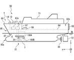
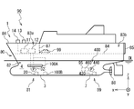
- FIG. 1A is a side view of a frictional resistance reduction type ship according to the first embodiment of the present invention.
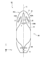
- FIG. 1B is a bottom view of the frictional resistance reduction ship.
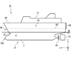
- FIG. 2 is a side view of a ship to be modified to a frictional resistance reduced ship.
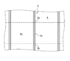
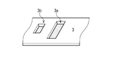
- FIG. 3 is a plan view of the hull outer plate provided on the bow portion of the ship's bow and on the side of the bottom of the ship as seen from the inside of the ship.
- FIG. 4 is a plan view of the hull outer plate provided on the bow bottom flat portion of the ship as viewed from inside the ship.
- FIG. 1A is a side view of a frictional resistance reduction type ship according to the first embodiment of the present invention.
- FIG. 1B is a bottom view of the frictional resistance reduction ship.
- FIG. 2 is a side view of a ship to be modified to a frictional resistance reduced ship.
- FIG. 3 is a plan view of the hull outer plate provided on the bow portion of the ship's
- FIG. 5 is a schematic cross-sectional view of an air blowing portion to be provided on the bow portion of the bottom of the ship.
- FIG. 6 is a schematic cross-sectional view of an air blowing portion to be provided on the bow bottom flat portion.
- FIG. 7 is a schematic perspective view of the seawater intake portion.
- FIG. 8 is a schematic diagram showing a process of forming an opening in a hull outer plate provided on the bow bottom flat portion.
- FIG. 9 is a schematic diagram showing a process of forming an opening in a hull outer plate provided on the side of the bow portion of the bottom of the ship.
- FIG. 10 is a schematic diagram showing a process of attaching an air blowing part to an opening formed in the hull outer plate of the bow part of the bottom of the ship.
- FIG. 10 is a schematic diagram showing a process of attaching an air blowing part to an opening formed in the hull outer plate of the bow part of the bottom of the ship.
- FIG. 11 is a schematic diagram showing a process of attaching an air blowing part to an opening formed in the hull outer plate of the bow part flat bottom.
- FIG. 12 is a schematic diagram showing a process of attaching the seawater intake part to the opening formed in the hull outer plate of the bow bottom flat part.
- FIG. 13 is a schematic diagram illustrating a process of installing a device such as an air supply device and a process of providing a partition wall.
- FIG. 14 is a schematic diagram illustrating a piping process and a wiring process.
- FIG. 15A is a side view of the air blowing part for the bow part of the bottom of the ship according to the second embodiment of the present invention.
- FIG. 15A is a side view of the air blowing part for the bow part of the bottom of the ship according to the second embodiment of the present invention.
- FIG. 15B is a cross-sectional view of the air blowing portion for the side portion of the bow portion of the ship's bottom.
- FIG. 15C is a bottom view of the air blowing part for the bow part of the ship's bottom.
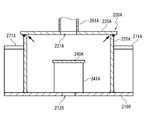
- FIG. 16 is a cross-sectional view of an air blowing portion according to a comparative example.
- FIG. 17A is a side view of an air blowing portion for a bow portion bottom flat portion according to the second embodiment.
- FIG. 17B is a cross-sectional view of the air blowing portion for the bow portion bottom flat portion.
- FIG. 17C is a bottom view of the air blowing portion for the bow portion flat bottom portion.
- FIG. 17A is a side view of an air blowing portion for a bow portion bottom flat portion according to the second embodiment.
- FIG. 17B is a cross-sectional view of the air blowing portion for the bow portion bottom flat portion.
- FIG. 17C is a bottom view of the air blowing portion for the bow portion flat bottom
- FIG. 18 is a schematic diagram showing a process of attaching the air blowing portion for the bow portion of the bottom of the ship to the bottom of the ship body on the side of the hull of the bottom portion of the ship's bottom.
- FIG. 19A is a side view of the air blowing portion for the bow portion of the bottom of the ship according to the third embodiment of the present invention.
- FIG. 19B is a cross-sectional view of the air blowing portion for the side portion of the bow portion of the ship's bottom.
- FIG. 19C is a bottom view of the air blowing portion for the bow portion at the bottom of the ship.
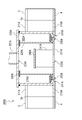
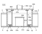
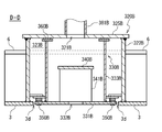
- FIG. 20A is a side view of the air blowing portion for the bow portion bottom flat portion according to the third embodiment.
- FIG. 20B is a cross-sectional view of the air blowing portion for the bow portion flat bottom portion.
- FIG. 20C is a bottom view of the air blowing portion for the bow portion flat bottom portion.
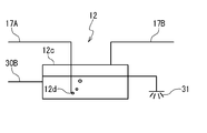
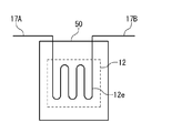
- FIG. 21 is a schematic view of an air cooler according to the fourth embodiment of the present invention.
- FIG. 22 is a schematic view of an air cooler according to the fifth embodiment of the present invention.
- FIG. 23 is a schematic view of an air cooler according to the sixth embodiment of the present invention.
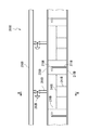
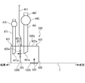
- FIG. 24 is a side view of a frictional resistance reduction ship according to the seventh embodiment of the present invention.
- FIG. 25 is a schematic view of a cooling system for a frictional resistance reduction ship according to a seventh embodiment.
- FIG. 26 is a side view of a ship to be modified to the frictional resistance reduction ship according to the seventh embodiment.
- FIG. 27 is a schematic diagram of a cooling system for a ship to be modified to the frictional resistance reduction ship according to the seventh embodiment.
- FIG. 28 is a schematic view of a cooling system according to the eighth embodiment of the present invention.
- the frictional resistance reduction ship is a ferry, but the frictional resistance reduction ship may be a ship other than a ferry.
- a frictional resistance reduction type ship 90 includes a hull 80, an air lubrication system 1, an upper structure 71, a rudder 72, and a propeller 88.
- a ship length direction (front-rear direction), a ship width direction (left-right direction) of the hull 80, and directions perpendicular thereto are shown as an x direction, a y direction, and a z direction, respectively.
- a line in contact with the water surface of the hull 80 floating on the still water surface is defined as a draft line DL.
- the term “boat bottom” means a portion of the hull 80 below the waterline DL.
- the hull 80 includes a bow bottom 80a, an air supply equipment room 83a, a hold 83b, a vehicle deck 84, a ramp 85, a deck exposing portion 86, a bulkhead 87, a hull outer plate 3, and a hull outer plate 4.
- the bow portion bottom 80 a includes a bow portion bottom flat portion 81 and a bow portion bottom side portion 82.
- the hull outer plate 3 is provided on the bow bottom flat portion 81.
- the hull skin 4 is provided on the bow side ship side portion 82.
- the air supply equipment room 83a is arranged on the bow side from the hold 83b.
- the air supply equipment room 83a and the boathouse 83b are partitioned by a partition wall 87.
- the vehicle deck 84 forms the floor surface of the air supply equipment room 83a and the hold 83b.
- the ramp 85 is used for the automobile 99 to get on and off the hold 83b.
- the deck exposure unit 86 is, for example, the upper deck of the bow, and is disposed above the air supply equipment room 83a.
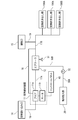
- the air lubrication system 1 includes an air supply device 11, an air cooler 12, a ventilating cylinder 13, an air suction port 14, an air blowing unit 100 ⁇ / b> A, an air blowing unit 100 ⁇ / b> B, a seawater intake unit 20, and a pump 32. .
- the air blowing part 100 ⁇ / b> A is arranged on the bow part bottom side ship side part 82.
- the air blowing part 100 ⁇ / b> B and the seawater intake part 20 are disposed on the bow bottom flat part 81.
- the air supply device 11 and the air cooler 12 are installed in the air supply device chamber 83a.
- the ventilation tube 13 and the air suction port 14 are installed in the deck exposure part 86.
- the ventilating cylinder 13 is connected to the air supply device room 83a and used to ventilate the air supply device room 83a.
- the air inlet 14 is connected to the air supply device 11.
- the air supply device 11 is connected to the air blowing units 100 ⁇ / b> A and 100 ⁇ / b> B via the air cooler 12.
- the seawater intake unit 20 is connected to the air cooler 12 via the pump 32.
- the seawater intake unit 20 and the air blowing unit 100B are disposed on, for example, the center line C, and are disposed on the ship bottom flat part 70 as a flat part of the ship bottom of the hull 80.
- the ship bottom flat part 70 includes a bow part ship bottom flat part 81.
- the bow bottom flat portion 81 is disposed at the deepest position in the y direction (the width direction) of the bow bottom 80a.
- the seawater intake part 20 is arranged on the bow side from the air blowing part 100B.
- the air blowing portions 100A are respectively arranged on both sides of the bow portion bottom side portion 82. When viewed from below, the seawater intake unit 20 is disposed between the air blowing units 100A provided on both sides.
- the air supply device 11 pressurizes the air sucked from the air suction port 14 to generate pressurized air, and supplies the pressurized air to the air blowing units 100A and 100B via the air cooler 12.
- the pump 32 supplies seawater taken from the seawater intake unit 20 to the air cooler 12.
- the air cooler 12 cools pressurized air using seawater.
- the air cooler 12 is, for example, a heat exchanger that exchanges heat between pressurized air and seawater.
- the air cooler 12 may be configured to cool the pressurized air by spraying seawater in the pressurized air, and may be configured to cool the pressurized air by blowing the pressurized air into the seawater. Also good.
- the air blowing units 100A and 100B blow out the pressurized air supplied from the air supply device 11 into the water.
- the air blowing units 100A and 100B blow out the pressurized air after cooling from the hull 80 into the water.
- the hull 80 is covered with bubbles formed by the air blown from the air blowing portions 100A and 100B, and the frictional resistance of the hull 80 is reduced.
- the cargo hold 83b in which the cargo such as the automobile 99 is mounted and the air supply device room 83a in which devices such as the air supply device 11 are installed are partitioned by the partition wall 87, fire prevention measures related to the air supply device 11 are taken. Applied. Further, the air blowing portions 100 ⁇ / b> A and 100 ⁇ / b> B are arranged at the bow portion of the hull 80 in order to increase the area covered with the bubbles of the hull 80. Since the air supply device chamber 83a in which the air supply device 11 is installed is on the bow side from the hold 83b, the piping length connecting the air supply device 11 and the air blowing portions 100A and 100B is shortened. Therefore, the construction period for the piping is shortened.
- the air supply device 11 pressurizes air to blow out air into the water against the water pressure. Therefore, the air at the outlet of the air supply device 11 is hot. If the hot air is blown out into the water without cooling, the deterioration of the paint film of the hull 80 may be accelerated. By blowing out the air cooled by the air cooler 12 into the water, deterioration of the coating film is suppressed.
- the seawater intake section 20 is disposed on the bow side from the air blowing section 100B, the air blown out by the air blowing section 100B is prevented from being mixed into the seawater taken from the seawater intake section 20. Further, since the seawater intake unit 20 is disposed at the deepest position in the y direction (ship width direction) of the bow portion bottom 80a and the seawater intake unit 20 is disposed between the air blowing units 100A when viewed from below, the air blowing unit. The air blown out by 100A is prevented from being mixed into the seawater taken from the seawater intake unit 20. Therefore, the seawater intake function of the pump 32 is prevented from being lowered, and the cooling capacity of the air cooler 12 is prevented from being lowered.
- the ship 91 includes a hull 80, an upper structure 71, a rudder 72, and a propeller 88.
- the hull 80 includes a bow bottom 80 a, a hold 83, a vehicle deck 84, a ramp 85, a deck exposure unit 86, a hull outer plate 3, and a hull outer plate 4.
- the bow portion bottom 80 a includes a bow portion bottom flat portion 81 and a bow portion bottom side portion 82.
- the hull outer plate 3 is provided on the bow bottom flat portion 81.
- the hull skin 4 is provided on the bow side ship side portion 82.
- the vehicle deck 84 forms the floor of the hold 83.
- the hold 83 is used for mounting a car.
- the ramp 85 is used for an automobile to get on and off the hold 83.
- the deck exposing portion 86 is, for example, the upper deck of the bow portion, and is disposed above the bow side portion of the hold 83.
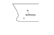
- FIG. 3 is a plan view of the hull skin 4 of the bow bottom ship side part 82 as seen from the inside of the ship.
- a plurality of frames 5 are provided along the hull outer plate 4.
- the plurality of frames 5 are parallel to each other.
- the frame 5 is formed in a plane perpendicular to the x direction.
- an opening is formed in the opening forming region 4c.
- the outline of the opening forming region 4c is indicated by a one-dot chain line.
- the opening forming region 4 c extends in the x direction across the plurality of frames 5.
- the contour line of the opening forming region 4 c intersects the frame 5 at positions 5 a and 5 b in the longitudinal direction of the frame 5.
- the frame 5 includes a removal portion 5c between the positions 5a and 5b.
- the removed portion 5c is cut off.
- end portions 5a and 5b corresponding to the positions 5a and 5b are formed on the frame 5, respectively.
- FIG. 4 is a plan view of the hull outer plate 3 of the bow bottom flat portion 81 as viewed from the inside of the ship.
- a plurality of longitudinal members 6 are provided along the hull outer plate 3.
- the plurality of stringers 6 are parallel to each other.
- the longitudinal member 6 is formed to extend in the x direction.
- an opening is formed in the opening forming region 3c.
- the outline of the opening forming region 3c is indicated by a one-dot chain line.
- the opening forming region 3 c extends in the y direction across the plurality of longitudinal members 6.
- the contour line of the opening forming region 3 c intersects the longitudinal member 6 at positions 6 a and 6 b in the longitudinal direction of the longitudinal member 6.
- the stringer 6 includes a removal portion 6c between the positions 6a and 6b.
- the removed portion 6c is cut off.
- end portions 6 a and 6 b corresponding to the positions 6 a and 6 b are formed in the longitudinal member 6.
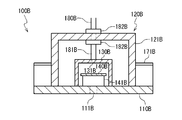
- the air blowing part 100A is manufactured. Specifically, first, a bottom plate 110A, a chamber 120A, an air blowing chamber 130A, a diffusion plate 140A, a support 141A, a structural member 171A, pipes 180A and 181A, and a flange 182A are prepared.
- the bottom plate 110A is a metal plate having substantially the same shape as the opening 4a formed in the hull outer plate 4 described later. This is because the bottom plate 110A is fitted into the opening 4a and the periphery of the bottom plate 110A is coupled to the hull outer plate 4 by welding or the like.
- the bottom plate 110A is, for example, a rectangular metal plate. However, the bottom plate 110A may have a shape slightly larger than the opening 4a. In this case, the overlapping portions are joined by a method such as welding, bolts, or rivets.
- the bottom plate 110A is formed with a plurality of air blowing holes 111A that are a plurality of through holes for blowing out air. Since it is necessary for the bottom plate 110 ⁇ / b> A to have a function as the hull outer plate 4, it is preferable that the bottom plate 110 ⁇ / b> A is formed of a plate having the same material and thickness as the hull outer plate 4.
- the diffusion plate 140A is attached to the bottom plate 110A via the support portion 141A so that the diffusion plate 140A faces the plurality of air blowing holes 111A at a predetermined distance.
- the air blowing chamber 130A is, for example, a rectangular parallelepiped metal chamber.
- An air inlet 131A as a through hole is formed on one surface (hereinafter also referred to as a first surface).
- Another surface (hereinafter also referred to as a second surface) facing the first surface is opened (opened) to be coupled to the bottom plate 110A.
- the pipe 181A is coupled to the air blowing chamber 130A so that the pipe 181A is connected to the air inlet 131A.
- the bottom plate 110A is coupled to the second surface of the air blowing chamber 130A so that the diffusion plate 140A and the plurality of air blowing holes 111A are covered with the air blowing chamber 130A.
- the diffusion plate 140A is disposed between the air inlet 131A and the air blowing hole 111A.
- the chamber 120A is coupled to the bottom plate 110A so as to cover the air blowing chamber 130A. Since the air blowing hole 111A is formed in the bottom plate 110A, in the state where the bottom plate 110A is coupled to the hull outer plate 4 of the bow part bottom side ship side 82 and the air blowing part 100A is attached to the opening 4a as described later.
- the air blowing chamber 130 ⁇ / b> A may be considered part of the bow bottom ship side 82. In that case, if the material, thickness, strength, etc. of the air blowing chamber 130A are not equivalent to the hull outer plate 4, the air blowing chamber 130A may not be officially recognized as a part of the bow bottom ship side portion 82. .
- the material of the chamber 120A, its thickness, strength, and the like are equivalent to those of the hull outer plate 4 so that the chamber 120A is publicly recognized as a recess structure of the bow bottom ship side portion 82.
- the chamber 120A is preferably large enough so that workers can work in it.
- the piping 181A is taken out from the chamber 120A through the flange 182A and connected to the piping 180A. Air supplied through the pipes 180A and 181A flows into the air blowing chamber 130A from the air inlet 131A. The inflowing air hits the diffusion plate 140A and diffuses, and then blows out from the air blowing hole 111A. The diffusion plate 140A prevents an increase in the flow rate of air blown from the air blowing holes 111A arranged in front of the air inlet 131A, and as a result, air is blown uniformly from the plurality of air blowing holes 111A. .
- the structural member 171A has a shape corresponding to the frame 5.
- the structural member 171A is welded to the wall material 121A and the bottom plate 110A of the chamber 120A.
- the structural member 171A includes a first structural member 171A disposed on one side of the chamber 120A and a second structural member 171A disposed on the other side of the chamber 120A.
- the chamber 120A is disposed between the first and second structural members 171A.
- the air blowing part 100B is manufactured. Specifically, first, a bottom plate 110B, a chamber 120B, an air blowing chamber 130B, a diffusion plate 140B, a support portion 141B, a structural member 171B, pipes 180B and 181B, and a flange 182B are prepared.
- the bottom plate 110B is a metal plate having substantially the same shape as the opening 3a formed in the hull outer plate 3 described later. This is because the bottom plate 110B is fitted into the opening 3a and the periphery of the bottom plate 110B is joined to the hull outer plate 3 by welding or the like.
- the bottom plate 110B is, for example, a rectangular metal plate. However, the bottom plate 110B may have a shape slightly larger than the opening 3a. In this case, the overlapping portions are joined by a method such as welding, bolts, or rivets.
- a plurality of air blowing holes 111B which are a plurality of through holes for blowing out air, are formed in the bottom plate 110B. Since the bottom plate 110 ⁇ / b> B needs to have a function as the hull outer plate 3, the bottom plate 110 ⁇ / b> B is preferably formed of a plate having the same material and thickness as the hull outer plate 3.
- the diffusion plate 140B is attached to the bottom plate 110B via the support portion 141B so that the diffusion plate 140B faces the plurality of air blowing holes 111B at a predetermined distance.
- the air blowing chamber 130B is, for example, a rectangular parallelepiped metal chamber.
- An air inlet 131B as a through hole is formed on one surface (hereinafter also referred to as a first surface).
- Another surface (hereinafter also referred to as a second surface) facing the first surface is opened (opened) in order to be coupled to the bottom plate 110B.
- the pipe 181B is coupled to the air blowing chamber 130B so that the pipe 181B is connected to the air inlet 131B.
- the bottom plate 110B is coupled to the second surface of the air blowing chamber 130B so that the diffusion plate 140B and the plurality of air blowing holes 111B are covered with the air blowing chamber 130B.
- the diffusion plate 140B is disposed between the air inlet 131B and the air blowing hole 111B.
- the chamber 120B is coupled to the bottom plate 110B so as to cover the air blowing chamber 130B. Since the air blowing hole 111B is formed in the bottom plate 110B, in a state where the bottom plate 110B is coupled to the hull outer plate 3 of the bow flat bottom portion 81 and the air blowing portion 100B is attached to the opening 3a as described later,
- the air blowing chamber 130 ⁇ / b> B may be regarded as a part of the bow bottom flat portion 81. In that case, if the material of the air blowing chamber 130B, its thickness, strength, etc. are not equivalent to the hull outer plate 3, the air blowing chamber 130B may not be officially recognized as part of the bow bottom flat portion 81. .
- the chamber 120B is publicly recognized as the recess structure of the bow bottom flat portion 81. Chamber 120B is preferably large enough so that workers can work in it.
- the piping 181B is taken out from the chamber 120B through the flange 182B and connected to the piping 180B.
- the air supplied through the pipes 180B and 181B flows into the air blowing chamber 130B from the air inlet 131B.
- the inflowing air hits the diffusion plate 140B and diffuses, and then blows out from the air blowing hole 111B.
- the diffusion plate 140B prevents an increase in the flow rate of air blown from the air blowing holes 111B disposed in front of the air inlet 131B, and as a result, air is blown uniformly from the plurality of air blowing holes 111B. .
- the structural member 171B has a shape corresponding to the longitudinal member 6.
- the structural member 171B is welded to the wall surface material 121B and the bottom plate 110B of the chamber 120B.
- the structural member 171B includes a first structural member 171B disposed on one side of the chamber 120B and a second structural member 171B disposed on the other side of the chamber 120B.
- the chamber 120B is disposed between the first and second structural members 171B.
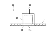
- the seawater intake unit 20 is manufactured. Specifically, first, a bottom plate 21, a sea chest 22, and a pipe 23 are prepared.
- the bottom plate 21 is a metal plate having substantially the same shape as the opening 3b formed in the hull outer plate 3 described later. This is because the bottom plate 21 is fitted into the opening 3b and the periphery of the bottom plate 21 is coupled to the hull outer plate 3 by welding or the like.
- the bottom plate 21 is, for example, a rectangular metal plate. However, the bottom plate 21 may have a shape slightly larger than the opening 3b. In this case, the overlapping portions are joined by a method such as welding, bolts, or rivets.
- the bottom plate 21 is formed with a seawater intake 21a which is a through hole for taking in seawater. In order to prevent foreign matter from entering the seawater intake portion 20, a lattice (not shown) is provided at the seawater intake port 21a. Since the bottom plate 21 needs to have a function as the hull outer plate 3, it is preferable that the bottom plate 21 is formed of a plate having the same material and thickness as the hull outer plate 3.
- the sea chest 22 is a rectangular parallelepiped metal chamber, for example.
- a seawater outlet as a through hole is formed on one surface (hereinafter also referred to as a first surface).
- the other surface (hereinafter also referred to as the second surface) facing the first surface is opened (opened) in order to be coupled to the bottom plate 21.
- the pipe 23 is coupled to the sea chest 22 so that the pipe 23 is connected to the seawater outlet.
- the bottom plate 21 is coupled to the second surface of the sea chest 22 so that the seawater intake port 21 a is covered with the sea chest 22. Seawater that has flowed into the sea chest 22 from the seawater intake port 21 a is supplied to the air cooler 12 through the pipe 23.
- another pipe (not shown) may be connected to the sea chest 22.
- the seawater intake 21a is formed in the bottom plate 21, in a state where the bottom plate 21 is coupled to the hull outer plate 3 of the bow bottom flat portion 81 and the seawater intake portion 20 is attached to the opening 3b as described later,
- the sea chest 22 needs to be publicly recognized as a part of the bow bottom flat portion 81. Accordingly, it is preferable that the material of the sea chest 22, its thickness, strength, and the like are equivalent to those of the hull outer plate 3. By doing so, the sea chest 22 is publicly recognized as a recess structure of the bow bottom flat portion 81.
- openings 3 a and 3 b are formed in the hull outer plate 3 of the bow bottom flat portion 81.
- the openings 3a and 3b are formed so that the opening 3b is closer to the bow than the opening 3a.
- the opening 3a is formed in the above-described opening forming region 3c.
- the cut portion 6 c is cut out from each longitudinal member 6, and ends 6 a and 6 b are formed on the longitudinal member 6.
- an opening 4 a is formed in the hull outer plate 4 of the bow bottom ship side portion 82.
- the opening 4a is formed in the above-described opening forming region 4c.
- the cut portion 5 c is cut from each frame 5, and end portions 5 a and 5 b are formed in the frame 5.
- the production of the air blowing part 100A and the formation of the opening 4a in the hull outer plate 4 may be performed first or may be performed simultaneously.
- Either the production of the air blowing portion 100B or the formation of the opening 3a in the hull outer plate 3 may be performed first or may be performed simultaneously.
- Either the production of the seawater intake portion 20 or the formation of the opening 3b in the hull outer plate 3 may be performed first or may be performed simultaneously.
- the dock use period is shortened by manufacturing the air blowing unit 100A, the air blowing unit 100B, and the seawater intake unit 20 in advance before putting the ship 91 in the dock.
- an air blowing part 100A is attached to the opening 4a formed in the hull outer plate 4.
- the air blowing portion 100A is inserted into the opening 4a of the hull outer plate 4 from the outside of the hull 80 toward the inside of the vessel.
- the chamber 120A is inserted toward the inside of the ship and the bottom plate 110A is inserted toward the outside of the ship. And it inserts to the position where the outer surface of the bottom plate 110A and the outer surface of the hull outer plate 4 are connected smoothly (without a step).
- the chamber 120A is disposed on the inner side of the ship, and the bottom plate 110A is fitted into the opening 4a with almost no gap.
- the bottom plate 110A is joined to the hull outer plate 4 by welding or the like, the first structural member 171A is joined to the end portion 5a of the frame 5 by welding or the like, and the second structural member 171A is joined to the end portion 5b of the frame 5. Connect by welding.
- the outer surface of the bottom plate 110A and the outer surface of the hull outer plate 4 are joined so as to form the same surface.
- the opening 4a has a shape slightly smaller than the bottom plate 110A
- the overlapping portions are joined by welding, bolts, rivets, or the like, and polished so as to smooth the step between the bottom plate 110A and the hull outer plate 4.
- the hull outer plate 4 and the bottom plate 110 ⁇ / b> A of the vessel 91 form the hull outer plate 4 of the frictional resistance reduction type vessel 90.
- the structural member 171 ⁇ / b> A to the frame 5 the frame 5 and the structural member 171 ⁇ / b> A of the ship 91 form a frame of the frictional resistance reduced ship 90.
- an air blowing portion 100 ⁇ / b> B is attached to the opening 3 a formed in the hull outer plate 3.
- the air blowing portion 100B is inserted into the opening 3a of the hull outer plate 3 from the outside of the hull 80 toward the inside of the vessel.
- the chamber 120B is inserted toward the inside of the ship and the bottom plate 110B is inserted toward the outside of the ship. And it inserts to the position where the outer surface of the bottom plate 110B and the outer surface of the hull outer plate 3 are smoothly connected (without a step).
- the chamber 120B is disposed on the inner side of the ship, and the bottom plate 110B is fitted into the opening 3a with almost no gap.
- the bottom plate 110B is joined to the hull outer plate 3 by welding or the like, the first structural member 171B is joined to the end 6a of the longitudinal member 6 by welding or the like, and the second structural member 171B is joined to the longitudinal member 6
- the end 6b is connected by welding or the like.
- the outer surface of the bottom plate 110B and the outer surface of the hull outer plate 3 are joined so as to form the same surface.
- the opening 3a has a shape slightly smaller than the bottom plate 110B, the overlapping portions are joined by welding, bolts, rivets, or the like, and polished so as to smooth the step between the bottom plate 110B and the hull outer plate 3.
- the hull outer plate 3 and the bottom plate 110 ⁇ / b> B of the ship 91 form the hull outer plate 3 of the frictional resistance reduction type ship 90.
- the structural member 171 ⁇ / b> B By connecting the structural member 171 ⁇ / b> B to the longitudinal member 6, the longitudinal member 6 and the structural member 171 ⁇ / b> B of the ship 91 form a longitudinal member of the frictional resistance reduced ship 90.
- the seawater intake 20 is attached to the opening 3 b formed in the hull outer plate 3. Specifically, the seawater intake portion 20 is inserted into the opening 3 b of the hull outer plate 3 from the outside of the hull 80 toward the inside of the vessel. At that time, the sea chest 22 is inserted toward the inside of the ship and the bottom plate 21 is inserted toward the outside of the ship. And it inserts to the position where the outer surface of the bottom plate 21 and the outer surface of the hull outer plate 3 are smoothly connected (without a step). As a result, the sea chest 22 is arranged on the inner side of the ship, and the bottom plate 21 is fitted into the opening 3b with almost no gap.
- the bottom plate 21 is joined to the hull outer plate 3 by welding or the like.
- the outer surface of the bottom plate 21 and the outer surface of the hull outer plate 3 are joined so as to form the same surface.
- the opening 3b has a shape slightly smaller than the bottom plate 21, the overlapping portions are joined by welding, bolts, rivets, or the like, and polished so as to smooth the step between the bottom plate 21 and the hull outer plate 3.
- the air blowing portion 100A, the air blowing portion 100B, and the seawater intake portion 20 are inserted into the opening 4a, the opening 3a, and the opening 3b from the outside of the ship, respectively.
- This method shortens the construction period in the case of manufacturing a frictional resistance-reduced ship 90 by remodeling a ship whose internal structure has already been completed, such as the ship 91.
- the opening 3b to which the seawater intake part 20 is attached is arranged on the bow side from the opening 3a to which the air blowing part 100B is attached, the air blown out by the air blowing part 100B is mixed into the seawater taken from the seawater intake part 20 It is prevented.
- Openings 4a to which the air blowing portion 100A is attached are formed on both sides of the bow bottom ship side portion 82, and the openings 3b to which the seawater intake portion 20 is attached are in the y direction (ship width direction) of the bow bottom flat portion 81.
- the opening 3b and the opening 4a are formed so as to be formed at the deepest portion and the opening 3b is disposed between the openings 4a. Therefore, the air blown out by the air blowing unit 100A is prevented from being mixed into the seawater taken in from the seawater intake unit 20.
- a partition wall 87 is provided so as to partition the hold 83 into a bow side portion 83a and a stern side portion 83b.
- the partition wall 87 is made of, for example, steel.
- the vehicle deck 84 forms the floor surface of the bow side portion 83a and the stern side portion 83b.
- the air supply device 11 and the air cooler 12 are installed on the bow side portion 83a.
- the air supply device 11 and the air cooler 12 are installed on the vehicle deck 84. Since the vehicle deck 84 has sufficient strength, the reinforcement work for installing the air supply device 11 and the air cooler 12 can be minimized.
- the ventilation cylinder 13 and the air inlet 14 are installed in the deck exposure part 86. Ventilation tube 13 is connected to bow side portion 83a.
- the bow side portion 83a is partitioned from the stern side portion 83b by the partition wall 87, but the bow side portion 83a is ventilated by the ventilation tube 13.
- the bow side portion 83a and the stern side portion 83b are used as the air supply equipment room 83a and the hold 83b in the frictional resistance reduction type ship 90, respectively. Since the bow-side portion 83a of the hold 83 is generally narrow in the y direction, there is little reduction in the capacity that can be used as a hold.
- the pump 32 is installed in the hull 80, the exhaust port 15 is installed in the deck exposure part 86, and the control panel 40 is installed in the bow side (air supply equipment room) 83a of the hold 83.
- the control panel 40 has a function of controlling the air supply device 11.
- the control panel 40 is an inverter panel, for example.
- the air supply device 11 includes a blower 11a that pressurizes air and a motor 11b that drives the blower 11a.
- the air suction port 14 and the inlet of the blower 11 a are connected by an air suction line 16.
- the outlet of the blower 11a and the air inlet of the air cooler 12 are connected by an air discharge line 17A.
- An air discharge line 17 ⁇ / b> B is connected to the air outlet of the air cooler 12.
- the pipe 180A of the air blowing part 100A is connected to the air discharge line 17B.
- the pipe 180B of the air blowing part 100B is connected to the air discharge line 17B.
- the exhaust port 15 and the air discharge line 17 ⁇ / b> B are connected by an exhaust line 19.
- the air discharge line 17B and the blower 11a are connected by an air return line 18.
- the piping 23 of the seawater intake unit 20 and the inlet of the pump 32 are connected by a cooling seawater line 30A. It is preferable to provide a strainer (not shown) in the cooling seawater line 30A.
- the outlet of the pump 32 and the seawater inlet of the air cooler 12 are connected by a cooling seawater line 30B.
- the seawater outlet of the air cooler 12 and the drain outlet 31 are connected.
- the control panel 40 and the motor 11b are connected with an electric wire.
- the air lubrication system 1 includes an exhaust port 15, a control panel 40, an air suction line 16, an air discharge line 17A, an air discharge line 17B, an exhaust line 19, an air return line 18, and a cooling seawater line 30A.
- a cooling seawater line 30B and a drain port 31 are provided.
- the seawater intake section 20 is disposed on the bow bottom 80a, the piping lengths of the cooling seawater lines 30A and 30B can be shortened. Therefore, the construction period in the case of manufacturing a frictional resistance reduced ship 90 by remodeling a ship having an internal structure already completed like the ship 91 is shortened.
- the air supply device 11 supplies the air sucked from the air suction port 14 to the air blowing portions 100A and 100B via the air cooler 12.
- the pump 32 supplies air taken from the seawater intake unit 20 to the air cooler 12.
- the air cooler 12 cools air using seawater.
- the drain port 31 has a function of draining seawater used for air cooling out of the ship.
- the air blowing parts 100A and 100B blow out the cooled air into the water.
- the air return line 18 has a function of partially returning the air cooled by the air cooler 12 from the air discharge line 17B to the blower 11a.
- the exhaust port 15 has a function of partially releasing the air cooled by the air cooler 12 into the atmosphere.
- connecting the air suction port 14 and the blower 11a with the air suction line 16 and connecting the motor 11b and the control panel 40 with an electric wire can be performed on the quay.
- the ship air lubrication system, the frictional resistance reduction type ship, and the manufacturing method thereof according to the present embodiment are the same as those of the ship according to the first embodiment in that the air blowing parts 100A and 100B are replaced with the air blowing parts 200A and 200B, respectively. It is different from the air lubrication system, the frictional resistance reduction type ship and its manufacturing method.
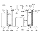
- an air blowing portion 200A includes a bottom plate 210A, an outer chamber 220A, an inner chamber 230A, a diffusion plate 240A, a support portion 241A, a structural member 270A, a structural member 271A, and a pipe 280A. And a branch pipe 281A and a valve 282A.
- the branch pipe 281A is branched from the pipe 280A.
- the valve 282A is provided in the branch pipe 281A.
- a plurality of inner chambers 230A are arranged inside the outer chamber 220A.
- a plurality of diffusion plates 240A and a plurality of branch pipes 281A are provided corresponding to the plurality of inner chambers 230A, respectively.
- the structural member 270A is disposed between the adjacent inner chambers 230A in the outer chamber 220A.
- the structural member 271A is disposed outside the outer chamber 220A.
- the pipe 280A is provided in parallel to the arrangement direction of the plurality of inner chambers 230A.
- the bottom plate 210A is a metal plate having substantially the same shape as the opening 4a formed in the hull outer plate 4. This is because the bottom plate 210A is fitted into the opening 4a and the periphery of the bottom plate 210A is joined to the hull outer plate 4 by welding or the like.
- the bottom plate 210A is, for example, a rectangular metal plate. However, the bottom plate 210A may have a shape slightly larger than the opening 4a. In this case, the overlapping portions are joined by a method such as welding, bolts, or rivets.
- the bottom plate 210 ⁇ / b> A needs to have a function as the hull outer plate 4, the bottom plate 210 ⁇ / b> A is preferably formed of a plate having the same material and thickness as the hull outer plate 4.
- the bottom plate 210A has a plurality of openings 211A corresponding to the plurality of inner chambers 230A, respectively.
- the outer chamber 220A is, for example, a rectangular parallelepiped metal chamber.
- a plurality of air inlets 221A as a plurality of through holes are formed in the upper surface member 225A forming one surface (hereinafter also referred to as a first surface).
- the plurality of air inlets 221A are formed corresponding to the plurality of inner chambers 230A, respectively.
- Another surface (hereinafter also referred to as a second surface) facing the first surface is opened (opened) in order to be coupled to the bottom plate 210A.
- the outer chamber 220A includes a pair of wall surfaces 222A. When the upper surface member 225A is regarded as a ceiling, the pair of wall surface materials 222A correspond to a pair of wall surfaces facing each other.
- the plurality of branch pipes 281A are coupled to the outer chamber 220A so that the plurality of branch pipes 281A are respectively connected to the plurality of air inlets 221A.
- the bottom plate 210A is coupled to the second surface of the outer chamber 220A so that the plurality of openings 211A are covered with the outer chamber 220A.
- the plurality of air inlets 221A face the plurality of openings 211A, respectively.
- the inner chamber 230A includes a cylindrical portion 233A that is open (opened) on both sides, and an air blowing plate 231A that closes one side of the cylindrical portion 233A.
- the inner chamber 230A is, for example, a metal chamber.
- a plurality of air blowing holes 232A are formed in the air blowing plate 231A.
- the diffusion plate 240A is disposed inside the inner chamber 230A.
- the diffusion plate 240A is attached to the air blowing plate 231A via the support portion 241A so that the diffusion plate 240A faces the plurality of air blowing holes 232A at a predetermined distance.
- the inner chamber 230A is attached to the outer chamber 220A with a screw part 250A in a state where the inner chamber 230A is disposed inside the outer chamber 220A so as to cover the air inlet 221A.
- the cylindrical portion 223A is disposed between the pair of wall surface materials 222A
- the sealing material 260A is disposed between the inner chamber 230A and the outer chamber 220A
- the inner chamber 230A is interposed via the sealing material 260A by the screw component 250A.
- the air blowing plate 231A is disposed in the opening 211A formed in the bottom plate 210A
- the diffusion plate 240A is disposed between the air inlet 221A and the air blowing hole 232A.
- the structural member 271A has a shape corresponding to the frame 5.
- the structural member 271A is coupled to the wall surface material 222A and the bottom plate 210A of the outer chamber 220A by welding or the like.
- the structural member 271A includes a first structural member 271A disposed on one side of the outer chamber 220A and a second structural member 271A disposed on the other side of the outer chamber 220A.
- the outer chamber 220A is disposed between the first and second structural members 271A.
- the first and second structural members 271A are arranged corresponding to the structural member 270A.
- the air supplied through the pipe 280A and the branch pipe 281A flows into the inner chamber 230A from the air inlet 221A.
- the inflowing air hits the diffusion plate 240A and diffuses, and then blows out from the air blowing hole 232A.
- the diffusion plate 240A prevents an increase in the flow rate of air blown from the air blowing holes 232A disposed in front of the air inlet 221A. As a result, air is blown uniformly from the plurality of air blowing holes 232A. .
- the air blowing portion 200A can blow out air from a wide range.
- the upper surface material 225A is joined to the wall material 222A by welding or the like to form the outer chamber 220A.
- the branch pipe 281A is coupled to the upper surface member 225A so as to be connected to the air inlet 221A.
- the structural member 271A is coupled to the bottom plate 210A and the wall surface material 222A by welding or the like.
- the inner chamber 230A to which the diffusion plate 240A is attached in advance is placed from the opening 211A of the bottom plate 210A to the outer chamber 220A with the other side (opening side) of the cylindrical portion 233A facing the top plate 225A (air inlet 221A). And is attached to the outer chamber 220A with a threaded part 250A. At that time, the screw member 250A is tightened in a state where the sealant 260A is disposed between the inner chamber 230A and the outer chamber 220A, and the inner chamber 230A is pressed against the outer chamber 220A.
- the outer chamber 220A is attached in a state where the bottom plate 110A is coupled to the hull outer plate 4 of the neck bottom side ship side portion 82 and the air blowing portion 200A is attached to the opening 4a as described later. May be considered part of the neck bottom side 82. In that case, it is preferable that the material, thickness, strength, and the like of the outer chamber 220A are equivalent to those of the hull skin 4 so that the outer chamber 220A is publicly recognized as a part of the neck bottom ship side portion 82. .
- the inner chamber 230A is attached to the outer chamber 220A with the screw part 250A, it is possible to weld the inside of the outer chamber 220A before attaching the inner chamber 230A to the outer chamber 220A. .
- the hermeticity and strength of the outer chamber 220A are improved.
- the outer chamber 220A may be large enough to allow a worker to insert a tool from the opening 211A and perform welding work, and may not be large enough to allow people to enter and exit. Therefore, it is easy to manufacture the air blowing portion 200A and attach the air blowing portion 200A to the opening 4a of the hull outer plate 4.
- the construction period for manufacturing the frictional resistance reduction type ship 90 is shortened, and in particular, the use period of the dock is shortened. It is also possible to remove the inner chamber 230A from the outer chamber 220A and perform maintenance of the air blowing part 200A.
- the diffusion plate 240A since the diffusion plate 240A is attached not to the outer chamber 220A but to the inner chamber 230A, the diffusion plate 240A does not get in the way when welding the inside of the outer chamber 220A.
- the effect of this embodiment becomes more apparent.
- the inner chamber 230A is not used, and the bottom plate 210X is used instead of the bottom plate 210A.
- An air blowing hole 212X is formed in the bottom plate 210X.
- the diffusion plate 240A is attached to the bottom plate 210X via the support portion 241A, and the wall surface material 222A is welded to the bottom plate 210X. Thereafter, the upper surface material 225A is welded to the wall surface material 222A to form the outer chamber 220A.
- the air blowing hole 212X is small, it is impossible to insert a tool into the outer chamber 220A and weld the inside of the outer chamber 220A. For example, the part pointed by the arrow in the figure cannot be welded.
- air blowing portion 200B includes bottom plate 210B, outer chamber 220B, inner chamber 230B, diffusion plate 240B, support portion 241B, structural member 270B, structural member 271B, and piping 280B. And a branch pipe 281B and a valve 282B.
- the branch pipe 281B is branched from the pipe 280B.
- the valve 282B is provided in the branch pipe 281B.
- a plurality of inner chambers 230B are arranged inside the outer chamber 220B.
- a plurality of diffusion plates 240B and a plurality of branch pipes 281B are provided corresponding to the plurality of inner chambers 230B, respectively.
- the structural member 270B is disposed between the adjacent inner chambers 230B in the outer chamber 220B.
- the structural member 271B is disposed outside the outer chamber 220B.
- the pipe 280B is provided in parallel to the arrangement direction of the plurality of inner chambers 230B.
- the bottom plate 210B is a metal plate having substantially the same shape as the opening 3a formed in the hull outer plate 3. This is because the bottom plate 210B is fitted into the opening 3a and the periphery of the bottom plate 210B is coupled to the hull outer plate 3 by welding or the like.
- the bottom plate 210B for example, a rectangular metal plate.
- the bottom plate 210B may have a shape slightly larger than the opening 3a. In this case, the overlapping portions are joined by a method such as welding, bolts, or rivets.
- the bottom plate 210 ⁇ / b> B needs to have a function as the hull outer plate 3
- the bottom plate 210 ⁇ / b> B is preferably formed of a plate having the same material and thickness as the hull outer plate 3.
- a plurality of openings 211B are formed in the bottom plate 210B corresponding to the plurality of inner chambers 230B, respectively.
- the outer chamber 220B is, for example, a rectangular parallelepiped metal chamber.
- a plurality of air inlets 221 ⁇ / b> B as a plurality of through holes are formed in the upper surface member 225 ⁇ / b> B forming one surface (hereinafter also referred to as a first surface).
- the plurality of air inlets 221B are formed corresponding to the plurality of inner chambers 230B, respectively.
- Another surface (hereinafter also referred to as a second surface) facing the first surface is opened (opened) in order to be coupled to the bottom plate 210B.
- the outer chamber 220B includes a pair of wall surfaces 222B.
- the pair of wall surface materials 222B correspond to a pair of wall surfaces facing each other.
- the plurality of branch pipes 281B are coupled to the outer chamber 220B so that the plurality of branch pipes 281B are connected to the plurality of air inlets 221B, respectively.
- the bottom plate 210B is coupled to the second surface of the outer chamber 220B so that the plurality of openings 211B are covered with the outer chamber 220B.
- the plurality of air inlets 221B face the plurality of openings 211B, respectively.
- the inner chamber 230B includes a cylindrical portion 233B that is open (opened) on both sides, and an air blowing plate 231B that closes one side of the cylindrical portion 233B.
- the inner chamber 230B is, for example, a metal chamber.
- a plurality of air blowing holes 232B are formed in the air blowing plate 231B.
- the diffusion plate 240B is disposed inside the inner chamber 230B.
- the diffusion plate 240B is attached to the air blowing plate 231B via the support portion 241B so that the diffusion plate 240B faces the plurality of air blowing holes 232B at a predetermined distance.
- the inner chamber 230B is attached to the outer chamber 220B with a screw part 250B in a state where the inner chamber 230B is disposed inside the outer chamber 220B so as to cover the air inlet 221B.
- the cylindrical portion 223B is disposed between the pair of wall surface members 222B
- the sealing material 260B is disposed between the inner chamber 230B and the outer chamber 220B
- the inner chamber 230B is interposed via the sealing material 260B by the screw component 250B.
- the air blowing plate 231B is disposed in the opening 211B formed in the bottom plate 210B
- the diffusion plate 240B is disposed between the air inlet 221B and the air blowing hole 232B.
- the structural member 271B has a shape corresponding to the longitudinal member 6.
- the structural member 271B is coupled to the wall surface material 222B and the bottom plate 210B of the outer chamber 220B by welding or the like.
- the structural member 271B includes a first structural member 271B disposed on one side of the outer chamber 220B and a second structural member 271B disposed on the other side of the outer chamber 220B.
- the outer chamber 220B is disposed between the first and second structural members 271B.
- the first and second structural members 271B are arranged corresponding to the structural member 270B.
- the inflowing air hits the diffusion plate 240B and diffuses, and then blows out from the air blowing hole 232B.
- the diffusion plate 240B prevents an increase in the flow rate of air blown from the air blowing holes 232B disposed in front of the air inlet 221B, and as a result, air is blown uniformly from the plurality of air blowing holes 232B. .
- the air blowing unit 200B can blow out air from a wide range.
- the air blowing unit 200B After the wall material 222B and the structural member 270B are joined to the bottom plate 210B by welding or the like, the upper surface material 225B is joined to the wall material 222B by welding or the like to form the outer chamber 220B.
- the branch pipe 281B is coupled to the upper surface material 225B so as to be connected to the air inlet 221B.
- the structural member 271B is coupled to the bottom plate 210B and the wall surface material 222B by welding or the like.
- a tool is inserted from the opening 211B formed in the bottom plate 210B to weld the inside of the outer chamber 220B.
- the inner chamber 230B to which the diffusion plate 240B is attached in advance is placed from the opening 211B of the bottom plate 210B to the outer chamber 220B with the other side (opening side) of the cylindrical portion 233B facing the top plate 225B (air inlet 221B). And is attached to the outer chamber 220B with a threaded part 250B. At that time, the screw member 250B is tightened in a state where the sealing material 260B is disposed between the inner chamber 230B and the outer chamber 220B, and the inner chamber 230B is pressed against the outer chamber 220B.
- the outer chamber 220B may be regarded as a part of the bow bottom flat portion 81.
- the material, thickness, strength, and the like of the outer chamber 220B may be equivalent to those of the hull skin 3 so that the outer chamber 220B is publicly recognized as a part of the bow bottom flat portion 81. preferable.
- the inner chamber 230B is attached to the outer chamber 220B with the screw part 250B, it is possible to weld the inside of the outer chamber 220B before attaching the inner chamber 230B to the outer chamber 220B. .
- the sealing property and strength of the outer chamber 220B are improved.
- the outer chamber 220B may be large enough to allow a worker to insert a tool from the opening 211B and perform welding work, and may not be large enough to allow people to enter and exit. Therefore, manufacture of the air blowing part 200B and attachment of the air blowing part 200B to the opening 3a of the hull outer plate 3 are easy.
- the construction period for manufacturing the frictional resistance reduction type ship 90 is shortened, and in particular, the use period of the dock is shortened. Further, it is possible to perform maintenance of the air blowing part 200B by removing the inner chamber 230B from the outer chamber 220B.
- the diffusion plate 240B since the diffusion plate 240B is attached not to the outer chamber 220B but to the inner chamber 230B, the diffusion plate 240B does not get in the way when welding the inside of the outer chamber 220B.
- an air blowing part 200 ⁇ / b> A is attached to the opening 4 a formed in the hull outer plate 4.
- the air blowing portion 200 ⁇ / b> A is inserted into the opening 4 a of the hull outer plate 4 from the outside of the hull 80 toward the inside of the vessel.
- the outer chamber 220A is inserted toward the inside of the ship and the bottom plate 210A is inserted toward the outside of the ship. And it inserts to the position where the outer surface of the bottom plate 210A and the outer surface of the hull outer plate 4 are connected smoothly (without a step).
- the outer chamber 220A is disposed inside the ship, and the bottom plate 210A fits into the opening 4a with almost no gap.
- the bottom plate 210A is joined to the hull outer plate 4 by welding or the like, the first structural member 271A is joined to the end portion 5a of the frame 5 by welding or the like, and the second structural member 271A is joined to the end portion 5b of the frame 5. Connect by welding.
- the outer surface of the bottom plate 210A and the outer surface of the hull outer plate 4 are joined so as to form the same surface.
- the opening 4a has a shape slightly smaller than the bottom plate 210A
- the overlapping portions are joined by welding, bolts, rivets, or the like, and polished so as to smooth the step between the bottom plate 210A and the hull outer plate 4.
- the hull outer plate 4 and the bottom plate 210A of the vessel 91 form the hull outer plate 4 of the frictional resistance reduction type vessel 90 by coupling the bottom plate 210A to the hull outer plate 4.
- the frame 5 and the structural member 271 ⁇ / b> A of the ship 91 form a frame of the frictional resistance reduced ship 90.
- the wall surface material 222A of the outer chamber 220A is formed to extend across the frame 5.
- the outer chamber 220A and the structural member 271A enhance the structure of the air blowing part 200A before the air blowing part 200A is attached to the opening 4a, and the friction resistance reducing type after the air blowing part 200A is attached to the opening 4a.
- the hull strength of the ship 90 is improved.
- the air supply device 11 and the air blowing part 200A are connected by connecting the pipe 280A of the air blowing part 200A to the air discharge line 17B. Thereby, the plurality of air inlets 221 ⁇ / b> A are connected to the air supply device 11.
- the air blowing portion 200A including the pipe 280A and the plurality of branch pipes 281A is attached to the opening 4a, the construction period in the dock is shortened.
- the method of attaching the air blowing part 200B to the opening 3a formed in the hull outer plate 3 is the same as the case of the air blowing part 200A.
- the air blowing portion 200B is inserted into the opening 3a of the hull outer plate 3 from the outside of the hull 80 toward the inside of the vessel.
- the outer chamber 220B is inserted toward the inside of the ship and the bottom plate 210B is inserted toward the outside of the ship. And it inserts to the position where the outer surface of the bottom plate 210B and the outer surface of the hull outer plate 3 are connected smoothly (without a step).
- the outer chamber 220B is disposed inside the ship, and the bottom plate 210B fits into the opening 3a with almost no gap.
- the bottom plate 210B is joined to the hull outer plate 3 by welding or the like, the first structural member 271B is joined to the end portion 6a of the longitudinal member 6 by welding or the like, and the second structural member 271B is joined to the longitudinal member 6.
- the end 6b is connected by welding or the like.
- the outer surface of the bottom plate 210B and the outer surface of the hull outer plate 3 are joined so as to form the same surface.
- the opening 3a has a shape slightly smaller than the bottom plate 210B
- the overlapping portions are joined by welding, bolts, rivets, or the like, and polished so as to smooth the step between the bottom plate 210B and the hull outer plate 3.
- the hull outer plate 3 and the bottom plate 210B of the vessel 91 form the hull outer plate 3 of the frictional resistance reduction type vessel 90.
- the structural member 271 ⁇ / b> B By connecting the structural member 271 ⁇ / b> B to the longitudinal member 6, the longitudinal member 6 and the structural member 271 ⁇ / b> B of the ship 91 form a longitudinal member of the frictional resistance reduced ship 90.
- the wall surface material 222B of the outer chamber 220B is formed so as to extend across the longitudinal member 6.
- the outer chamber 220B and the structural member 271B strengthen the structure of the air blowing part 200B before the air blowing part 200B is attached to the opening 3a, and the frictional resistance reduction type after the air blowing part 200B is attached to the opening 3a.
- the hull strength of the ship 90 is improved.
- the air supply unit 11 and the air blowing part 200B are connected by connecting the pipe 280B of the air blowing part 200B to the air discharge line 17B. Thereby, the plurality of air inlets 221 ⁇ / b> B are connected to the air supply device 11.
- the air blowing portion 200B including the pipe 280B and the plurality of branch pipes 281B is attached to the opening 3a, the construction period in the dock is shortened.
- the air blowing portions 100A and 100B are replaced with the air blowing portions 300A and 300B, respectively, and the opening 3a is formed in the hull outer plate 3.
- a plurality of openings are formed so as not to cut the longitudinal member 6, and instead of forming the openings 4a in the hull outer plate 4, a plurality of openings are formed so as not to cut the frame 5.
- the manufacturing method according to the present embodiment is suitable for manufacturing the frictional resistance reduced ship 90 as a new shipbuilding.
- the air blowing section 300A includes an outer chamber 320A, an inner chamber 330A, a diffusion plate 340A, a support section 341A, a pipe 380A, a branch pipe 381A, and a valve 382A.
- the branch pipe 381A is branched from the pipe 380A.
- the valve 382A is provided in the branch pipe 381A.
- the plurality of outer chambers 320 ⁇ / b> A are arranged in a direction (for example, the x direction) intersecting the frame 5.
- One outer chamber 320 ⁇ / b> A is provided between adjacent frames 5.
- a plurality of inner chambers 330A are respectively disposed inside the plurality of outer chambers 320A.
- a plurality of branch pipes 281A are provided corresponding to the plurality of outer chambers 320A, respectively.
- a plurality of diffusion plates 340A are provided corresponding to the plurality of inner chambers 330A, respectively.
- the pipe 380A is provided in parallel to the arrangement direction of the plurality of outer chambers 320A. That is, the pipe 380A is parallel to the arrangement direction of the plurality of inner chambers 330A.
- the outer chamber 320A is, for example, a rectangular parallelepiped metal chamber.
- the outer chamber 320A includes an upper surface material 325A that forms one surface (hereinafter also referred to as a first surface) and a pair of wall surface materials 323A.
- the top surface member 325 ⁇ / b> A is regarded as a ceiling
- the pair of wall surface materials 323 ⁇ / b> A correspond to a pair of wall surfaces facing each other in a direction intersecting the frame 5.
- the hull outer plate 4 has a plurality of openings 4d as a plurality of through holes corresponding to the plurality of inner chambers 330A, respectively.
- the plurality of openings 4d are formed in the opening forming region 4c.
- the plurality of openings 4d correspond to the plurality of outer chambers 320A, respectively.
- An air inlet 321A is formed in the upper surface member 325A of the outer chamber 320A.
- Another surface (hereinafter also referred to as a second surface) facing the first surface of the outer chamber 320A is opened (opened) so as to be coupled to the hull outer plate 4.
- the outer chamber 320A includes a pair of wall surfaces 322A.
- the pair of wall surface materials 322 ⁇ / b> A correspond to a pair of wall surfaces facing each other in the longitudinal direction of the frame 5.
- the branch pipe 381A is coupled to the upper surface member 325A of the outer chamber 320A so that the branch pipe 381A is connected to the air inlet 321A.
- the hull skin 4 is coupled to the second surface of the outer chamber 320A so that the opening 4d is covered by the outer chamber 320A.
- the outer chamber 320A is coupled to the hull skin 4 from the inside of the ship.
- the air inlet 321A faces the opening 4d.
- the inner chamber 330A includes a cylindrical portion 333A that is open (opened) on both sides, and an air blowing plate 331A that closes one side of the cylindrical portion 333A.
- the inner chamber 330A is, for example, a metal chamber.
- a plurality of air blowing holes 332A are formed in the air blowing plate 331A.
- the diffusion plate 340A is disposed inside the inner chamber 330A.
- the diffusion plate 340A is attached to the air blowing plate 331A via the support portion 341A so that the diffusion plate 340A faces the plurality of air blowing holes 332A at a predetermined distance.
- the inner chamber 330A With the inner chamber 330A disposed inside the outer chamber 320A so as to cover the air inlet 321A, the inner chamber 330A is attached to the outer chamber 320A with a screw part 350A.
- the cylindrical portion 323A is disposed between the pair of wall surface materials 322A and between the pair of wall surface materials 323A
- the sealing material 360A is disposed between the inner chamber 330A and the outer chamber 320A
- the inner chamber is formed by the screw component 350A.
- 330A is pressed against the outer chamber 320A through the sealant 360A
- the air blowing plate 331A is disposed in the opening 4d formed in the hull outer plate 4
- the diffusion plate 340A is disposed between the air inlet 321A and the air blowing hole 332A. Placed in.
- an opening 4d is formed in a portion between adjacent frames 5 of the hull outer plate 4.
- the frame 5 is not cut by the air blowing part 300A.
- the air supplied through the pipe 380A and the branch pipe 381A flows into the inner chamber 330A from the air inlet 321A.
- the inflowing air hits the diffusion plate 340A and diffuses, and then blows out from the air blowing hole 332A.
- the diffusion plate 340A prevents an increase in the flow rate of air blown from the air blowing holes 332A arranged in front of the air inlet 321A, and as a result, air is blown uniformly from the plurality of air blowing holes 232A. .
- the air blowing unit 300A can blow out air from a wide range.
- the upper surface material 325A is joined to the wall materials 322A and 323A by welding or the like to form the outer chamber 320A.
- the branch pipe 381A is coupled to the upper surface member 225A so as to be connected to the air inlet 321A.
- a tool is inserted from the opening 4d formed in the hull outer plate 4 to weld the inside of the outer chamber 320A.
- the inner chamber 330A to which the diffusion plate 340A is attached in advance, is opened in the hull outer plate 4 with the other side (opening side) of the cylindrical portion 333A facing the upper surface plate 325A (air inlet 321A). 4d is inserted into the outer chamber 320A and attached to the outer chamber 320A with a screw part 350A.
- the screw member 350A is tightened in a state where the sealant 360A is disposed between the inner chamber 330A and the outer chamber 320A, and the inner chamber 330A is pressed against the outer chamber 320A.
- the outer chamber 320A may be regarded as a part of the bow bottom ship side part 82.
- the material, thickness, strength, and the like of the outer chamber 320A may be equivalent to those of the hull skin 4 so that the outer chamber 320A is publicly recognized as a part of the bow bottom ship side portion 82. preferable.
- the air supply device 11 and the air blowing part 300A are connected by connecting the pipe 380A of the air blowing part 300A to the air discharge line 17B. Thereby, the plurality of air inlets 321 ⁇ / b> A are connected to the air supply device 11.
- the air blowing section 300B includes an outer chamber 320B, an inner chamber 330B, a diffusion plate 340B, a support section 341B, a pipe 380B, a branch pipe 381B, and a valve 382B.
- the branch pipe 381B is branched from the pipe 380B.
- the valve 382B is provided in the branch pipe 381B.
- the plurality of outer chambers 320 ⁇ / b> B are arranged in a direction (for example, the y direction) intersecting the longitudinal member 6.
- One outer chamber 320B is provided between the adjacent stringers 6.
- a plurality of inner chambers 330B are respectively disposed inside the plurality of outer chambers 320B.
- a plurality of branch pipes 281B are provided corresponding to the plurality of outer chambers 320B, respectively.
- a plurality of diffusion plates 340B are provided corresponding to the plurality of inner chambers 330B, respectively.
- the pipe 380B is provided in parallel to the arrangement direction of the plurality of outer chambers 320B. That is, the pipe 380B is parallel to the arrangement direction of the plurality of inner chambers 330B.
- the outer chamber 320B is a rectangular parallelepiped metal chamber, for example.
- the outer chamber 320B includes an upper surface material 325B that forms one surface (hereinafter also referred to as a first surface) and a pair of wall surface materials 323B.
- the pair of wall surface materials 323B correspond to a pair of wall surfaces facing each other in a direction intersecting with the longitudinal member 6.
- the hull outer plate 3 is formed with a plurality of openings 3d as a plurality of through holes corresponding to the plurality of inner chambers 330B, respectively.
- the plurality of openings 3d are formed in the opening forming region 3c. Therefore, the opening 3b is disposed on the bow side from the plurality of openings 3d.
- the plurality of openings 3d correspond to the plurality of outer chambers 320B, respectively.
- An air inflow port 321B is formed in the upper surface member 325B of the outer chamber 320B.
- Another surface (hereinafter also referred to as a second surface) facing the first surface of the outer chamber 320B is opened (opened) so as to be coupled to the hull outer plate 3.
- the outer chamber 320B includes a pair of wall surfaces 322B.
- the pair of wall surface materials 322B correspond to a pair of wall surfaces facing each other in the longitudinal direction of the longitudinal member 6.
- the branch pipe 381B is coupled to the upper surface member 325B of the outer chamber 320B so that the branch pipe 381B is connected to the air inlet 321B.
- the hull skin 3 is coupled to the second surface of the outer chamber 320B so that the opening 3d is covered by the outer chamber 320B.
- the outer chamber 320B is coupled to the hull skin 3 from the inside of the ship.
- the air inlet 321b faces the opening 3d.
- the inner chamber 330B includes a cylindrical portion 333B that is open (opened) on both sides, and an air blowing plate 331B that closes one side of the cylindrical portion 333B.
- the inner chamber 330B is, for example, a metal chamber.
- a plurality of air blowing holes 332B are formed in the air blowing plate 331B.
- the diffusion plate 340B is disposed inside the inner chamber 330B.
- the diffusion plate 340B is attached to the air blowing plate 331B via the support portion 341B so that the diffusion plate 340B faces the plurality of air blowing holes 332B at a predetermined distance.
- the inner chamber 330B is attached to the outer chamber 320B with a screw part 350B in a state where the inner chamber 330B is disposed inside the outer chamber 320B so as to cover the air inlet 321B.
- the cylindrical portion 323B is disposed between the pair of wall surface materials 322B and between the pair of wall surface materials 323B
- the sealing material 360B is disposed between the inner chamber 330B and the outer chamber 320B
- the inner chamber is formed by the screw component 350B.
- the air blowing plate 331B is disposed in the opening 3d formed in the hull outer plate 3
- the diffusion plate 340B is located between the air inlet 321B and the air blowing hole 332B. Placed in.
- an opening 3 d is formed in a portion between adjacent longitudinal members 6 of the hull outer plate 3.
- the stringer 6 is not cut by the air blowing part 300B.
- the inflowing air hits the diffusion plate 340B and diffuses, and then blows out from the air blowing hole 332B.
- the diffusion plate 340B prevents an increase in the flow rate of air blown from the air blowing holes 332B disposed in front of the air inlet 321B, and as a result, air is blown uniformly from the plurality of air blowing holes 232B. .
- the air blowing unit 300B can blow out air from a wide range.
- the air blowing unit 300B After the wall materials 322B and 323B are joined to the hull outer plate 3 by welding or the like, the upper surface material 325B is joined to the wall materials 322B and 323B by welding or the like to form the outer chamber 320B.
- the branch pipe 381B is coupled to the upper surface material 225B so as to be connected to the air inlet 321B.
- a tool is inserted from the opening 3d formed in the hull outer plate 3 to weld the inside of the outer chamber 320B.
- the outer chamber 320B may be regarded as a part of the bow flat bottom portion 81.
- the material, thickness, strength, and the like of the outer chamber 320B may be equivalent to those of the hull skin 3 so that the outer chamber 320B is publicly recognized as a part of the bow portion bottom flat portion 81. preferable.
- the air supply device 11 and the air blowing part 300B are connected by connecting the pipe 380B of the air blowing part 300B to the air discharge line 17B. Thereby, the plurality of air inlets 321 ⁇ / b> B are connected to the air supply device 11.
- the frame 5 is not cut by the air blowing portion 300A, and the longitudinal member 6 is not cut by the air blowing portion 300B. Therefore, it is easy to ensure the hull strength of the frictional resistance reduced ship 90.
- the ship air lubrication system, the frictional resistance reduction type ship, and the manufacturing method thereof according to the present embodiment are the same as the ship air lubrication system, the frictional resistance reduction type ship, and the method according to the first to third embodiments. Different from the manufacturing method.
- the air cooler 12 includes a duct 12a and a nozzle 12b.
- the nozzle 12b is disposed in the duct 12a.
- the outlet of the blower 11a and the air inlet of the duct 12a are connected by an air discharge line 17A.
- An air discharge line 17B is connected to the air outlet of the duct 12a.
- the outlet of the pump 32 and the nozzle 12b are connected by a cooling seawater line 30B.
- the seawater outlet of the duct 12a and the drain outlet 31 are connected.
- Air supplied from the air supply device 11 flows into the duct 12a.
- the nozzle 12b sprays seawater supplied from the pump 32 into the air to cool the air.
- the cooled air is supplied to the air blowing parts 100A, 100B, 200A, 200B, 300A, or 300B through the air discharge line 17B. Seawater used for cooling the air is drained out of the ship through a drain port 31.
- the ship air lubrication system, the frictional resistance reduction type ship, and the manufacturing method thereof according to the present embodiment are the same as the ship air lubrication system, the frictional resistance reduction type ship, and the method according to the first to third embodiments. Different from the manufacturing method.
- the air cooler 12 includes a seawater tank 12c and an air outlet 12d.
- the air outlet 12d is disposed in the seawater tank 12c.
- the outlet of the blower 11a and the air outlet 12d are connected by an air discharge line 17A.
- An air discharge line 17B is connected to the air outlet of the seawater tank 12c.
- the outlet of the pump 32 and the seawater inlet of the seawater tank 12c are connected by a cooling seawater line 30B.
- the seawater outlet of the seawater tank 12c and the drain 31 are connected.
- Seawater is supplied from the pump 32 to the seawater tank 12c.
- the seawater tank 12c stores a certain amount of seawater.
- the drain port 31 discharges the seawater overflowing from the seawater tank 12c to the outside of the ship.
- the air outlet 12d blows air supplied from the air supply device 11 into seawater.
- the air cooled by the seawater is supplied to the air blowing parts 100A, 100B, 200A, 200B, 300A, or 300B through the air discharge line 17B.
- the ship air lubrication system, the frictional resistance reduction type ship, and the manufacturing method thereof according to the present embodiment are the same as the ship air lubrication system, the frictional resistance reduction type ship, and the method according to the first to third embodiments. Different from the manufacturing method.
- a ballast tank 50 for storing ballast seawater is provided in the hull 80.
- the air cooler 12 includes an air pipe 12e disposed in the ballast tank.
- the outlet of the blower 11a and the inlet of the air pipe 12e are connected by an air discharge line 17A.
- An air discharge line 17B is connected to the outlet of the air pipe 12e.
- the air supplied from the air supply device 11 is cooled by seawater in the ballast tank 50 when flowing in the air pipe 12e.
- the cooled air is supplied to the air blowing parts 100A, 100B, 200A, 200B, 300A, or 300B through the air discharge line 17B.
- the frictional resistance reduction type ship according to the present embodiment includes the following configuration in addition to the configuration of the frictional resistance reduction type ship according to the first to sixth embodiments.
- the frictional resistance reduction ship 90 includes a cooling system 400.
- the hull 80 includes a stern part bottom 89 and a hull outer plate 7 provided on the stern part bottom 89.
- the cooling system 400 includes a sea chest 420 as a seawater intake unit, a seawater pump 440, and a cooler 460.
- the sea chest 420 is disposed on the stern part bottom 89.
- the seawater pump 440 sucks seawater from the stern part bottom 89 through the sea chest 420 and supplies it to the cooler 460.
- the cooler 460 cools the cooling target device 95 using seawater.
- the cooling target device 95 is, for example, a main machine that drives the propeller 88.
- the sea chest 420 may be provided at a place other than the stern part bottom 89.
- the cooling capacity of the cooler 460 decreases.
- the frictional resistance reduction type ship 90 in order to reduce the frictional resistance of the hull 80, air is blown into the water from the air blowing parts 100A and 100B (200A and 200B or 300A and 300B). Therefore, the amount of air flowing into the sea chest 420 increases. It is necessary to prevent air from entering the cooling seawater supplied to the cooler 460.
- the cooling system 400 includes a seawater pump 470, a seawater suction pipe 441, a seawater supply pipe 442, a seawater suction pipe 471, air vent pipes 451 to 453, and air separation. Instruments 454 and 455.
- the seawater pumps 440 and 470 are, for example, spiral pumps.
- the air separators 454 and 455 are, for example, cyclone air separators.
- the sea chest 420 includes chambers 421 to 424, partition walls 425 to 427, and a car template 435.
- the ceiling 420a of the sea chest 420 forms the ceiling of each of the chambers 421 to 424.
- the floor 420b of the sea chest 420 forms the respective floors of the chambers 421 to 424.
- the floor 420b forms the same plane as the hull outer plate 7 provided on the stern part bottom 89.
- the chambers 421 and 422 are separated by a partition wall 425.
- Chambers 422 and 423 are partitioned by a partition wall 426.
- the chambers 423 and 424 are separated by a partition wall 427.
- the car template 435 is provided so as to protrude downward from the ceiling 423 a of the chamber 423, and is disposed between the partition wall 426 and the partition wall 427.
- the chamber 422 is disposed on the bow side of the chamber 421, the chamber 423 is disposed on the bow side of the chamber 422, and the chamber 424 is disposed on the bow side of the chamber 423.
- a seawater inlet 430 is formed in the floor 424 b of the chamber 424.
- a seawater passage port 427 a is formed in the partition wall 427, a seawater passage port 426 a is formed in the partition wall 426, and a seawater passage port 425 a is formed in the partition wall 425.
- the seawater passage ports 425a to 427a are away from the ceiling 420a and away from the floor 420b.
- the lower end of the car template 435 is disposed at a position lower than the lower end of the seawater passage port 427a and the lower end of the seawater passage port 426a.
- the seawater suction pipe 441 extends downward from the ceiling 422a of the chamber 422.
- a seawater suction port 441 a is formed at the lower end of the seawater suction pipe 441.
- the seawater inlet 441a is disposed in the chamber 422 at a position lower than the seawater passages 425a and 426a.
- Seawater suction pipe 441 is connected to a suction port of seawater pump 440.
- the seawater supply pipe 442 connects the discharge port of the seawater pump 440 and the seawater inlet of the cooler 460.
- the seawater suction pipe 471 extends downward from the ceiling 421a of the chamber 421.
- a seawater suction port 471 a is formed at the lower end of the seawater suction pipe 471.
- the seawater inlet 471a is disposed in the chamber 421 at a position lower than the seawater passage 425a.
- Seawater suction pipe 471 is connected to the suction port of seawater pump 470.
- Air vents 431 and 432 are formed in the ceiling 422 a of the chamber 422.
- the air vent pipe 451 connects the air vent 431 and the air separator 454.
- the air vent tube 452 connects the air vent 432 and the air separator 455.
- the chamber 423 includes a portion 423c between the car template 435 and the partition wall 427 and a portion 423d between the car template 435 and the partition wall 426.
- the ceiling 423a of the chamber 423 includes a portion corresponding to the portion 423c.
- An air vent 433 is formed in a portion corresponding to the portion 423c of the ceiling 423a.
- the air vent tube 453 connects the air vent 433 and the air separator 455.
- Seawater is taken into the chamber 424 from the stern bottom 89 through the seawater inlet 430. Seawater flows from the chamber 424 into the portion 423c of the chamber 423 through the seawater passage port 427a. Seawater passes under the car template 435 and flows from the portion 423 c of the chamber 423 to the portion 423 d of the chamber 423. Seawater flows into the chamber 422 from the portion 423d of the chamber 423 through the seawater passage port 426a.
- the seawater pump 440 sucks a part of the seawater that has flowed into the chamber 422 from the seawater suction port 441 a and supplies the sear to the cooler 460.
- the cooler 460 cools the cooling target device 95 using the supplied seawater.
- the seawater pump 470 sucks the seawater that has flowed into the chamber 421 from the seawater suction port 471a and supplies the seawater to, for example, a sanitary tank.
- Air accumulated in the vicinity of the ceiling of the portion 423c of the chamber 423 is discharged out of the ship via the air vent pipe 453 and the air separator 455.
- the air separator 455 separates air and seawater.
- the separated seawater is discharged, for example, by a pipe of a scapper (not shown).
- the car template 435 prevents air from moving from the portion 423 c of the chamber 423 to the portion 423 d. As a result, the amount of air flowing into the chamber 422 is reduced.
- the lower end of the car template 435 is disposed at a position lower than the lower end of the seawater passage port 427a and the lower end of the seawater addition port 426a, so that the car template 435 passes through the lower side of the chamber 423 and the portions 423c to 423d The amount of air that moves to is further reduced.
- the air collected in the vicinity of the ceiling 422a of the chamber 422 is discharged to the outside of the ship via the air vent pipe 451 and the air separator 454, and is discharged to the outside of the ship via the air vent pipe 452 and the air separator 455.
- the air separator 454 separates air and seawater.
- the separated seawater is discharged, for example, by a pipe of a scapper (not shown). Since air is exhausted by the two air vent pipes 451 and 452, air is efficiently exhausted from the chamber 422. Since the seawater suction port 441a is disposed at a position lower than the seawater passage port 426a, the downward flow of the seawater can be formed in the chamber 422 so that the flow velocity thereof is slower than the rising speed of the bubbles. Since a descending flow of seawater is formed, air is prevented from flowing into the seawater inlet 441a.
- the seawater suction port 471a is disposed at a position lower than the seawater passage port 425a, the downward flow of the seawater can be formed in the chamber 421 so that the flow velocity is slower than the rising speed of the bubbles. Therefore, the air is prevented from flowing into the seawater inlet 471a. As a result, the seawater pump 470 is prevented from being damaged by the air mixed in the seawater.
- the ship 91 includes a cooling system 500.
- the hull 80 includes a stern part bottom 89 and a hull outer plate 7 provided on the stern part bottom 89.
- the cooling system 500 includes a sea chest 520 as a seawater intake unit, a seawater pump 440, and a cooler 460.
- the sea chest 520 is disposed on the stern part bottom 89.
- the seawater pump 440 sucks seawater from the stern part bottom 89 through the sea chest 520 and supplies it to the cooler 460.
- the cooler 460 cools the cooling target device 95 using seawater.
- the cooling target device 95 is, for example, a main machine that drives the propeller 88.
- cooling system 500 includes seawater pump 470, seawater suction pipe 441, seawater supply pipe 442, seawater suction pipe 471, and air vent pipe 451.
- the sea chest 520 includes chambers 421 and 422 and partition walls 425 and 426.
- the ceiling 520a of the sea chest 520 forms the ceiling of each of the chambers 421 and 422.
- the floor 520b of the sea chest 520 forms the respective floor of the chambers 421 and 422.
- the floor 520 b forms the same surface as the hull skin 7 provided on the stern part bottom 89.
- the chambers 421 and 422 are separated by a partition wall 425.
- the partition wall 426 forms the outer wall surface of the sea chest 520.
- the chamber 422 is disposed on the bow side of the chamber 421.
- a seawater intake 530 is formed in the floor 422 b of the chamber 422.
- a seawater passage port 425 a is formed in the partition wall 425. The seawater passage port 425a is away from the ceiling 520a and away from the floor 520b.
- the seawater suction pipe 441 extends downward from the ceiling 422a of the chamber 422.
- a seawater suction port 441 a is formed at the lower end of the seawater suction pipe 441.
- the seawater inlet 441a is disposed in the chamber 422 at a position lower than the seawater passage 425a.
- Seawater suction pipe 441 is connected to a suction port of seawater pump 440.
- the seawater supply pipe 442 connects the discharge port of the seawater pump 440 and the seawater inlet of the cooler 460.
- the seawater suction pipe 471 extends downward from the ceiling 421a of the chamber 421.
- a seawater suction port 471 a is formed at the lower end of the seawater suction pipe 471.
- the seawater inlet 471a is disposed in the chamber 421 at a position lower than the seawater passage 425a.
- Seawater suction pipe 471 is connected to the suction port of seawater pump 470.
- An air vent 431 is formed in the ceiling 422 a of the chamber 422.
- the air vent pipe 451 is connected to the air vent 431.
- Seawater is taken into the chamber 422 from the stern bottom 89 through the seawater intake 530.
- the seawater pump 440 sucks a part of the seawater that has flowed into the chamber 422 from the seawater suction port 441 a and supplies the sear to the cooler 460.
- the cooler 460 cools the cooling target device 95 using the supplied seawater.
- the remainder of the seawater that has flowed into the chamber 422 passes through the seawater passage port 425a and flows into the chamber 421.
- the seawater pump 470 sucks the seawater that has flowed into the chamber 421 from the seawater suction port 471a and supplies the seawater to, for example, a sanitary tank.
- the manufacturing method of the frictional resistance reduction ship according to the present embodiment includes the following steps in addition to the processes of the manufacturing method of the frictional resistance reduction ship according to the first to sixth embodiments.
- the sea chest 520 is expanded to form a sea chest 420.
- the chamber 423 is formed on the bow side of the chamber 422.
- the chambers 422 and 423 are partitioned by a partition wall 426.
- a seawater passage port 426 a is formed in the partition wall 426.
- a chamber 424 is formed on the bow side of the chamber 423.
- the chambers 423 and 424 are partitioned by a partition wall 427.
- a seawater passage port 427 a is formed in the partition wall 427.
- the seawater intake 530 is closed, and the seawater intake 430 is formed in the floor 424 b of the chamber 424.
- a car template 435 is provided between the partition wall 426 and the partition wall 427 and protrudes downward from the ceiling of the chamber 423.
- the chamber 423 includes a portion 423 c between the car template 435 and the partition wall 427.
- the air vent 433 is formed in a portion corresponding to the portion 423c of the ceiling 423a of the chamber 423.
- An air vent tube 453 is connected to the air vent port 433.
- An air separator 455 is connected to the air vent tube 453.
- An air vent 432 is formed in the ceiling 422 a of the chamber 422.
- An air vent tube 452 is connected to the air vent port 432.
- An air separator 455 is connected to the air vent tube 452.
- An air separator 454 is connected to the air vent pipe 451.
- the seawater suction pipe 441 is extended so that the seawater suction inlet 441a of the seawater suction pipe 441 is disposed at a position lower than the seawater passage openings 425a and 426a.
- the seawater suction pipe 471 is extended so that the seawater suction opening 471a of the seawater suction pipe 471 is disposed at a position lower than the seawater passage opening 425a.
- the frictional resistance reduction ship according to an eighth embodiment of the present invention includes the following configuration.
- a ballast tank 50 for storing ballast seawater is provided in the hull 80.
- An air vent pipe 51 is connected to the upper part of the ballast tank 50.
- the cooling system 400 according to the present embodiment further includes a seawater supply pipe 443, a seawater pump 490, a seawater suction pipe 491, a seawater supply pipe 492, an overflow drain pipe 480, and drain ports 481 and 482.
- the seawater supply pipe 443 connects the discharge port of the seawater pump 440 and the ballast tank 50.
- the seawater suction pipe 491 connects the suction port of the seawater pump 490 and the ballast tank 50.
- the seawater supply pipe 492 connects the discharge port of the seawater pump 490 and the seawater inlet of the cooler 460.
- the seawater outlet of the cooler 460 is connected to the drain outlet 482.
- the overflow drain pipe 480 connects the ballast tank 50 and the drain port 481.
- the seawater pump 440 supplies seawater sucked from the seawater inlet 441a of the seawater inlet pipe 441 to the ballast tank 50 through the seawater supply pipe 443.
- the seawater pump 490 supplies seawater sucked from the ballast tank 50 through the seawater suction pipe 491 to the cooler 460 through the seawater supply pipe 492.
- Seawater that has flowed out of the cooler 460 is discharged out of the ship through a drain outlet 482.
- the overflow drain pipe 480 discharges the seawater overflowing from the ballast tank 50 from the drain port 481 to the outside of the ship. Air enters and exits the ballast tank 50 through the air vent pipe 51.
- air is separated from seawater in the ballast tank 50. Therefore, air can be prevented from being mixed into the seawater supplied to the cooler 460.
- the ship 91 to be modified includes a ballast tank 50.
- An air vent pipe 51 is connected to the upper part of the ballast tank 50.
- the cooling system 500 included in the ship 91 includes an overflow drain pipe 480 and drain ports 481 and 482.
- the overflow drain pipe 480 connects the drain port 481 and the ballast tank 50.
- the drain port 482 is connected to the seawater outlet of the cooler 460.
- the manufacturing method of the frictional resistance reduced ship according to the present embodiment includes the following steps in addition to the process of the manufacturing method of the frictional resistance reduced ship according to the seventh embodiment.
- the discharge port of the seawater pump 440 and the ballast tank 50 are connected by the seawater supply pipe 443.
- the suction port of the seawater pump 490 and the ballast tank 50 are connected by a seawater suction pipe 491.
- the discharge port of the seawater pump 490 and the seawater inlet of the cooler 460 are connected by a seawater supply pipe 492.
- the ship air lubrication system, the frictional resistance reduction ship and the manufacturing method thereof according to the present invention have been described above with reference to the embodiments.
- the present invention is not limited to the above embodiments. Combinations of the above embodiments, and modifications to the above embodiments are also included in the present invention.
- the frictional resistance reduction type ship according to the first to eighth embodiments may be manufactured by modifying an existing ship or may be manufactured as a new ship.
Landscapes
- Physics & Mathematics (AREA)
- Fluid Mechanics (AREA)
- Chemical & Material Sciences (AREA)
- Engineering & Computer Science (AREA)
- Combustion & Propulsion (AREA)
- Mechanical Engineering (AREA)
- Ocean & Marine Engineering (AREA)
- Filling Or Discharging Of Gas Storage Vessels (AREA)
- Structures Of Non-Positive Displacement Pumps (AREA)
Abstract
船舶の空気潤滑システムは、空気供給装置と、空気吹き出し部及びと、エアクーラとを具備する。空気吹き出し部及びは、空気供給装置から供給される空気を水中に吹き出す。エアクーラは、海水を用いてその空気を冷却する。
Description
本発明は、船舶に関し、特に摩擦抵抗低減型船舶に関する。
船舶の船体に作用する摩擦抵抗を低減する一手法として、空気(気泡)を水中に吹き出して船体表面を気泡で覆う方法が知られている。
関連する技術として、特開2010-120607号公報(特許文献1)に船体摩擦抵抗低減装置が開示されている。船体摩擦抵抗低減装置は、船底に形成された複数の空気噴出孔群から気泡を発生させて船底に気泡膜を形成することにより、航行する船体の摩擦抵抗を低減する。複数の空気噴出孔群の各々は、船体の船幅方向に並んだ複数の空気噴出孔を含む。複数の空気噴出孔群は、少なくとも、中央空気噴出孔群と、一対の側方空気噴出孔群とを含む。中央空気噴出孔群は、船首側の船幅方向中央に形成される。一対の側方空気噴出孔群は、中央空気噴出孔群の船尾側且つ船幅方向の両側方に形成される。中央空気噴出孔群の船幅方向の長さは、側方空気噴出孔群の船幅方向の長さより長い。
摩擦抵抗低減型船舶においては、空気を水中に吹き出すためにブロアのような空気供給装置が搭載される。空気供給装置は、水圧に抗して空気を吹き出すために空気を加圧する。そのため、空気供給装置の出口における空気は高温である。その高温空気を冷却せずに水中に吹き出すと、船体表面の塗装膜の劣化が加速されるおそれがある。
本発明の目的は、塗装膜の劣化が抑制される船舶の空気潤滑システム、摩擦抵抗低減型船舶及びその製造方法を提供することである。
本発明の第1の観点による船舶の空気潤滑システムは、空気供給装置と、前記空気供給装置から供給される空気を水中に吹き出す空気吹き出し部と、海水を用いて前記空気を冷却するエアクーラとを具備する。
空気供給装置は、水圧に抗して空気を吹き出すために空気を加圧する。そのため、空気供給装置の出口における空気は高温である。その高温空気を冷却せずに水中に吹き出すと、船体表面の塗装膜の劣化が加速されるおそれがある。クーラにより塗装膜の劣化が抑制される。
好ましくは、上記船舶の空気潤滑システムは、前記海水を取り入れる海水取入部を更に具備する。前記空気吹き出し部及び前記海水取入部は船首部船底に配置される。前記海水取入部は前記空気吹き出し部より船首側に配置される。
海水取入部が船首部船底に配置されるため、海水取入部とエアクーラとを接続する配管を短くすることができる。空気吹き出し部より船首側に海水取入部が配置されるため、海水取入部から取り入れられる海水に空気吹き出し部が吹き出した空気が混入することが防止される。
好ましくは、上記船舶の空気潤滑システムは、前記海水を取り入れる海水取入部を更に具備する。前記空気吹き出し部は船首部船底の船側部の両舷にそれぞれ配置される。前記海水取入部は前記船首部船底の船幅方向の最深位置に配置される。前記海水取入部は前記空気吹き出し部の間に配置される。
海水取入部が船首部船底に配置されるため、海水取入部とエアクーラとを接続する配管を短くすることができる。海水取入部が船首部船底の船幅方向の最深位置に配置され、海水取入部が空気吹き出し部の間に配置されるため、空気吹き出し部が吹き出した空気が海水取入部から取り入れられる海水に混入することが防止される。
好ましくは、前記エアクーラは、前記空気と前記海水とを熱交換する熱交換器を備える。
好ましくは、前記エアクーラは、前記空気中に海水を噴霧するノズルを備える。
好ましくは、前記エアクーラは、前記海水中に前記空気を吹き出す空気吹き出し口を備える。
好ましくは、前記エアクーラは、前記海水を貯えるバラストタンク内に配置される空気配管を備える。前記空気配管を前記空気が流れる。
本発明の第2の観点による摩擦抵抗低減型船舶は、空気供給装置と、前記空気供給装置から供給される空気を水中に吹き出す空気吹き出し部と、海水を用いて前記空気を冷却するエアクーラと、前記空気吹き出し部が設けられる船体とを具備する。
本発明の第3の観点による摩擦抵抗低減型船舶の製造方法は、空気吹き出し部を船舶に設けることと、海水取入部を前記船舶に設けることと、前記空気吹き出し部に空気を供給する空気供給装置を前記船舶に設けることと、前記海水取入部から取り入れた海水を用いて前記空気を冷却するエアクーラを前記船舶に設けることとを具備する。
空気供給装置は、水圧に抗して空気を吹き出すために空気を加圧する。そのため、空気供給装置の出口における空気は高温である。その高温空気を冷却せずに水中に吹き出すと、船体表面の塗装膜の劣化が加速されるおそれがある。クーラにより塗装膜の劣化が抑制される。
好ましくは、前記空気吹き出し部を前記船舶に設けることにおいて、前記空気吹き出し部を船首部船底に配置する。前記海水取入部を前記船舶に設けることにおいて、前記海水取入部を前記船首部船底に配置する。前記空気吹き出し部を前記船舶に設けること又は前記海水取入部を前記船舶に設けることにおいて、前記海水取入部が前記空気吹き出し部より船首側になるように、前記空気吹き出し部を配置し又は前記海水取入部を配置する。
海水取入部が船首部船底に配置されるため、海水取入部とエアクーラとを接続する配管を短くすることができる。したがって、船舶を改造して摩擦抵抗低減型船舶を製造する場合の工期が短縮される。空気吹き出し部より船首側に海水取入部が配置されるため、海水取入部から取り入れられる海水に空気吹き出し部が吹き出した空気が混入することが防止される。
好ましくは、前記空気吹き出し部を前記船舶に設けることにおいて、前記空気吹き出し部を船首部船底の船側部の両舷にそれぞれ配置する。前記海水取入部を前記船舶に設けることにおいて、前記海水取入部を前記船首部船底の船幅方向の最深位置に配置する。前記空気吹き出し部を前記船舶に設けること又は前記海水取入部を前記船舶に設けることにおいて、前記海水取入部が前記空気吹き出し部の間に配置されるように、前記空気吹き出し部を配置し又は前記海水取入部を配置する。
海水取入部が船首部船底に配置されるため、海水取入部とエアクーラとを接続する配管を短くすることができる。したがって、船舶を改造して摩擦抵抗低減型船舶を製造する場合の工期が短縮される。海水取入部が船首部船底の船幅方向の最深位置に配置され、海水取入部が空気吹き出し部の間に配置されるため、海水取入部から取り入れられる海水に空気吹き出し部が吹き出した空気が混入することが防止される。
好ましくは、前記空気吹き出し部を前記船舶に設けることは、前記船舶の船体外板に第1開口部を形成することと、前記空気吹き出し部を船外から前記第1開口部に挿入することと、前記空気吹き出し部を前記第1開口部に取り付けることとを備える。前記海水取入部を前記船舶に設けることは、前記船舶の船体外板に第2開口部を形成することと、前記海水取入部を船外から前記第2開口部に挿入することと、前記海水取入部を前記第2開口部に取り付けることとを備える。
空気吹き出し部を船外から第1開口部に挿入し、海水取入部を船外から第2開口部に挿入するため、船舶を改造して摩擦抵抗低減型船舶を製造する場合の工期が短縮される。
本発明の第4の観点による船舶の空気潤滑方法は、空気を加圧して加圧空気を生成することと、海水を用いて前記加圧空気を冷却することと、前記加圧空気を船体から水中に吹き出すこととを具備する。
本発明によれば、塗装膜の劣化が抑制される船舶の空気潤滑システム、摩擦抵抗低減型船舶及びその製造方法が提供される。
本発明の上記目的、他の目的、効果、及び特徴は、添付される図面として連携して実施の形態の記述から、より明らかになる。
図1Aは、本発明の第1の実施形態に係る摩擦抵抗低減型船舶の側面図である。
図1Bは、摩擦抵抗低減型船舶の底面図である。
図2は、摩擦抵抗低減型船舶に改造されるべき船舶の側面図である。
図3は、船舶の船首部船底船側部に設けられた船体外板を船内から見た平面図である。
図4は、船舶の船首部船底平坦部に設けられた船体外板を船内から見た平面図である。
図5は、船首部船底船側部に設けられるべき空気吹き出し部の概略断面図である。
図6は、船首部船底平坦部に設けられるべき空気吹き出し部の概略断面図である。
図7は、海水取入部の概略斜視図である。
図8は、船首部船底平坦部に設けられた船体外板に開口部を形成する工程を示す模式図である。
図9は、船首部船底船側部に設けられた船体外板に開口部を形成する工程を示す模式図である。
図10は、船首部船底船側部の船体外板に形成された開口部に空気吹き出し部を取り付ける工程を示す模式図である。
図11は、船首部船底平坦部の船体外板に形成された開口部に空気吹き出し部を取り付ける工程を示す模式図である。
図12は、船首部船底平坦部の船体外板に形成された開口部に海水取入部を取り付ける工程を示す模式図である。
図13は、空気供給装置等の機器を設置する工程及び隔壁を設ける工程を示す模式図である。
図14は、配管工程及び配線工程を示す模式図である。
図15Aは、本発明の第2の実施形態に係る船首部船底船側部用空気吹き出し部の側面図である。
図15Bは、船首部船底船側部用空気吹き出し部の断面図である。
図15Cは、船首部船底船側部用空気吹き出し部の底面図である。
図16は、比較例に係る空気吹き出し部の断面図である。
図17Aは、第2の実施形態に係る船首部船底平坦部用空気吹き出し部の側面図である。
図17Bは、船首部船底平坦部用空気吹き出し部の断面図である。
図17Cは、船首部船底平坦部用空気吹き出し部の底面図である。
図18は、船首部船底船側部の船体外板に形成された開口部に船首部船底船側部用空気吹き出し部を取り付ける工程を示す模式図である。
図19Aは、本発明の第3の実施形態に係る船首部船底船側部用空気吹き出し部の側面図である。
図19Bは、船首部船底船側部用空気吹き出し部の断面図である。
図19Cは、船首部船底船側部用空気吹き出し部の底面図である。
図20Aは、第3の実施形態に係る船首部船底平坦部用空気吹き出し部の側面図である。
図20Bは、船首部船底平坦部用空気吹き出し部の断面図である。
図20Cは、船首部船底平坦部用空気吹き出し部の底面図である。
図21は、本発明の第4の実施形態に係るエアクーラの概略図である。
図22は、本発明の第5の実施形態に係るエアクーラの概略図である。
図23は、本発明の第6の実施形態に係るエアクーラの概略図である。
図24は、本発明の第7の実施形態に係る摩擦抵抗低減型船舶の側面図である。
図25は、第7の実施形態に係る摩擦抵抗低減型船舶の冷却システムの概略図である。
図26は、第7の実施形態に係る摩擦抵抗低減型船舶に改造されるべき船舶の側面図である。
図27は、第7の実施形態に係る摩擦抵抗低減型船舶に改造されるべき船舶の冷却システムの概略図である。
図28は、本発明の第8の実施形態に係る冷却システムの概略図である。
添付図面を参照して、本発明による船舶の空気潤滑システム、摩擦抵抗低減型船舶及びその製造方法を実施するための形態を以下に説明する。以下の説明において摩擦抵抗低減型船舶はフェリーであるが、摩擦抵抗低減型船舶はフェリー以外の船舶であってもよい。
(第1の実施形態)
以下、本発明の第1の実施形態に係る船舶の空気潤滑システム、摩擦抵抗低減型船舶及びその製造方法を説明する。
以下、本発明の第1の実施形態に係る船舶の空気潤滑システム、摩擦抵抗低減型船舶及びその製造方法を説明する。
図1Aを参照して、本実施形態に係る摩擦抵抗低減型船舶90は、船体80と、空気潤滑システム1と、上部構造71と、舵72と、プロペラ88とを備える。船体80の船長方向(前後方向)、船幅方向(左右方向)及びそれらいずれにも垂直な方向が、それぞれx方向、y方向及びz方向として示されている。静水面に浮いている船体80の水面と接する線を喫水線DLとする。用語「船底」は、船体80の喫水線DLより下の部分を意味する。
船体80は、船首部船底80aと、空気供給機器室83aと、船倉83bと、車両甲板84と、ランプ85と、甲板暴露部86と、隔壁87と、船体外板3と、船体外板4とを備える。船首部船底80aは、船首部船底平坦部81と、船首部船底船側部82とを備える。船体外板3は船首部船底平坦部81に設けられる。船体外板4は船首部船底船側部82に設けられる。空気供給機器室83aは、船倉83bより船首側に配置される。空気供給機器室83a及び船倉83bは隔壁87によって仕切られている。車両甲板84は、空気供給機器室83a及び船倉83bの床面を形成する。ランプ85は、自動車99が船倉83bに乗り降りするために使用される。甲板暴露部86は、例えば、船首部の上甲板であり、空気供給機器室83aの上方に配置される。
空気潤滑システム1は、空気供給装置11と、エアクーラ12と、通風筒13と、空気吸い込み口14と、空気吹き出し部100Aと、空気吹き出し部100Bと、海水取入部20と、ポンプ32とを備える。空気吹き出し部100Aは、船首部船底船側部82に配置される。空気吹き出し部100B及び海水取入部20は、船首部船底平坦部81に配置される。空気供給装置11及びエアクーラ12は、空気供給機器室83aに設置される。通風筒13及び空気吸い込み口14は、甲板暴露部86に設置される。通風筒13は、空気供給機器室83aに接続され、空気供給機器室83aを換気するために用いられる。空気吸い込み口14は空気供給装置11に接続される。空気供給装置11は、エアクーラ12を介して空気吹き出し部100A及び100Bに接続される。海水取入部20は、ポンプ32を介してエアクーラ12に接続される。
図1Bを参照して、海水取入部20及び空気吹き出し部100Bは、例えば、センターラインC上に配置され、船体80の船底の平坦な部分としての船底平坦部70に配置される。船底平坦部70は船首部船底平坦部81を含む。船首部船底平坦部81は、船首部船底80aのy方向(船幅方向)の最深位置に配置される。海水取入部20は空気吹き出し部100Bより船首側に配置される。空気吹き出し部100Aは、船首部船底船側部82の両舷にそれぞれ配置される。下から見て海水取入部20は、両舷に設けられた空気吹き出し部100Aの間に配置される。
空気供給装置11は、空気吸い込み口14から吸い込んだ空気を加圧して加圧空気を生成し、その加圧空気をエアクーラ12を介して空気吹き出し部100A及び100Bに供給する。ポンプ32は、海水取入部20から取り入れられた海水をエアクーラ12に供給する。エアクーラ12は、海水を用いて加圧空気を冷却する。エアクーラ12は、例えば、加圧空気と海水を熱交換する熱交換器である。或いは、エアクーラ12は、加圧空気中に海水を散布して加圧空気を冷却するように構成されてもよく、海水中に加圧空気を吹き出して加圧空気を冷却するように構成されてもよい。空気吹き出し部100A及び100Bは、空気供給装置11から供給された加圧空気を水中に吹き出す。空気吹き出し部100A及び100Bは、冷却後の加圧空気を船体80から水中に吹き出す。空気吹き出し部100A及び100Bから吹き出された空気により形成される気泡で船体80が覆われて、船体80の摩擦抵抗が低減される。
ここで、自動車99等の貨物が搭載される船倉83bと空気供給装置11等の機器が設置される空気供給機器室83aとが隔壁87で仕切られるため、空気供給装置11に関連した防火対策が施される。また、船体80の気泡で覆われる面積を大きくするために空気吹き出し部100A及び100Bは船体80の船首部に配置される。空気供給装置11が設置される空気供給機器室83aが船倉83bより船首側であるため、空気供給装置11と空気吹き出し部100A及び100Bとを接続する配管長が短くなる。そのため、その配管のための工期が短縮される。
空気供給装置11は、水圧に抗して空気を水中に吹き出すために空気を加圧する。そのため、空気供給装置11の出口における空気は高温である。その高温空気を冷却せずに水中に吹き出すと、船体80の塗装膜の劣化が加速されるおそれがある。エアクーラ12によって冷却された空気を水中に吹き出すことで、塗装膜の劣化が抑制される。
海水取入部20が空気吹き出し部100Bより船首側に配置されるため、空気吹き出し部100Bが吹き出した空気が海水取入部20から取り入れられる海水に混入することが防止される。更に、船首部船底80aのy方向(船幅方向)の最深位置に海水取入部20が配置され、下から見て海水取入部20が空気吹き出し部100Aの間に配置されるため、空気吹き出し部100Aが吹き出した空気が海水取入部20から取り入れられる海水に混入することが防止される。そのため、ポンプ32の海水取入機能低下が防止され、エアクーラ12の冷却能力の低下が防がれる。
次に、摩擦抵抗低減型船舶90の製造方法に含まれる工程を説明する。
ここでは、図2に示された船舶91を改造して摩擦抵抗低減型船舶90を製造する方法を説明する。船舶91は、船体80と、上部構造71と、舵72と、プロペラ88とを備える。船体80について、上述のようにx方向、y方向及びz方向が定義される。船体80は、船首部船底80aと、船倉83と、車両甲板84と、ランプ85と、甲板暴露部86と、船体外板3と、船体外板4とを備える。船首部船底80aは、船首部船底平坦部81と、船首部船底船側部82とを備える。船体外板3は船首部船底平坦部81に設けられる。船体外板4は船首部船底船側部82に設けられる。車両甲板84は船倉83の床面を形成する。船倉83は、自動車を搭載するために利用される。ランプ85は、自動車が船倉83に乗り降りするために使用される。甲板暴露部86は、例えば、船首部の上甲板であり、船倉83の船首側部分の上方に配置される。
図3は、船首部船底船側部82の船体外板4を船内から見た平面図である。船体外板4に沿って複数のフレーム5が設けられている。複数のフレーム5は互いに平行である。フレーム5は、x方向に垂直な平面内に形成されている。船舶91を摩擦抵抗低減型船舶90に改造するために、開口部形成領域4cに開口部が形成される。開口部形成領域4cの輪郭線が一点鎖線で示されている。開口部形成領域4cは、複数のフレーム5にまたがってx方向に延びている。開口部形成領域4cの輪郭線は、フレーム5の長手方向の位置5a及び5bにおいて、フレーム5と交差している。フレーム5は、位置5a及び5bの間の除去部分5cを含む。開口部形成領域4cに開口部を形成する際、除去部分5cが切り取られる。このとき、位置5a及び5bにそれぞれ対応する端部5a及び5bがフレーム5に形成される。
図4は、船首部船底平坦部81の船体外板3を船内から見た平面図である。船体外板3に沿って複数の縦通材6が設けられている。複数の縦通材6は互いに平行である。縦通材6は、x方向に延びるように形成されている。船舶91を摩擦抵抗低減型船舶90に改造するために、開口部形成領域3cに開口部が形成される。開口部形成領域3cの輪郭線が一点鎖線で示されている。開口部形成領域3cは、複数の縦通材6にまたがってy方向に延びている。開口部形成領域3cの輪郭線は、縦通材6の長手方向の位置6a及び6bにおいて、縦通材6と交差している。縦通材6は、位置6a及び6bの間の除去部分6cを含む。開口部形成領域3cに開口部を形成する際、除去部分6cが切り取られる。このとき、位置6a及び6bにそれぞれ対応する端部6a及び6bが縦通材6に形成される。
図5に示すように、空気吹き出し部100Aを製作する。具体的には、まず、底板110Aと、チャンバ120Aと、空気吹き出しチャンバ130Aと、拡散板140Aと、支持部141Aと、構造部材171Aと、配管180A及び181Aと、フランジ182Aとを準備する。
底板110Aは、後述される船体外板4に形成される開口部4aとほぼ同じ形状を有する金属板である。底板110Aを開口部4aに嵌めて底板110Aの周辺を溶接等により船体外板4に結合するためである。底板110Aは、例えば、矩形形状の金属板である。ただし、底板110Aは、開口部4aよりやや大きい形状としてもよい。この場合、重なり部分を溶接、ボルト、リベット等の方法で結合する。底板110Aには、空気を吹き出すための複数の貫通孔である複数の空気吹き出し孔111Aが形成されている。底板110Aは、船体外板4としての機能も有する必要があるため、船体外板4と同一材料且つ同一厚みの板で形成されることが好ましい。
拡散板140Aが所定の距離を隔てて複数の空気吹き出し孔111Aと向かい合うように、拡散板140Aを支持部141Aを介して底板110Aに取り付ける。
空気吹き出しチャンバ130Aは、例えば直方体形状の金属チャンバである。一つの面(以下、第1面ともいう)に貫通孔としての空気流入口131Aが形成されている。第1面と向かい合う他の一つの面(以下、第2面ともいう)は、底板110Aと結合するために開放(開口)されている。配管181Aが空気流入口131Aに接続されるように、配管181Aを空気吹き出しチャンバ130Aに結合する。拡散板140A及び複数の空気吹き出し孔111Aが空気吹き出しチャンバ130Aに覆われるように、底板110Aを空気吹き出しチャンバ130Aの第2面に結合する。ここで、拡散板140Aは、空気流入口131Aと空気吹き出し孔111Aとの間に配置される。
空気吹き出しチャンバ130Aを覆うように、チャンバ120Aを底板110Aに結合する。底板110Aに空気吹き出し孔111Aが形成されているため、後述するように底板110Aを船首部船底船側部82の船体外板4に結合して空気吹き出し部100Aを開口部4aに取り付けた状態において、空気吹き出しチャンバ130Aが船首部船底船側部82の一部とみなされる可能性がある。その場合、空気吹き出しチャンバ130Aの材料、その厚み及び強度などが船体外板4と同等ではない場合、空気吹き出しチャンバ130Aが船首部船底船側部82の一部として公的に認められない場合がある。そのため、チャンバ120Aの材料、その厚み及び強度などを、船体外板4と同等のものとすることにより、チャンバ120Aを船首部船底船側部82のレセス構造として公的に認められるようにする。チャンバ120Aは、その中で作業員が作業をできるように十分大きいことが好ましい。
配管181Aをフランジ182Aを介してチャンバ120Aから外に取り出し、配管180Aに接続する。配管180A及び181Aを通って供給される空気は、空気流入口131Aから空気吹き出しチャンバ130A内に流入する。その流入空気は、拡散板140Aにぶつかって拡散した後、空気吹き出し孔111Aから外に吹き出す。拡散板140Aにより、空気流入口131Aの正面に配置される空気吹き出し孔111Aから吹き出される空気流量が多くなることが防止され、その結果、複数の空気吹き出し孔111Aから均一に空気が吹き出される。
構造部材171Aは、フレーム5に対応する形状を有している。構造部材171Aをチャンバ120Aの壁面材121A及び底板110Aに溶接する。構造部材171Aは、チャンバ120Aの一方側に配置される第1の構造部材171Aと、チャンバ120Aの他方側に配置される第2の構造部材171Aとを含む。チャンバ120Aは第1及び第2の構造部材171Aの間に配置される。
図6に示すように、空気吹き出し部100Bを製作する。具体的には、まず、底板110Bと、チャンバ120Bと、空気吹き出しチャンバ130Bと、拡散板140Bと、支持部141Bと、構造部材171Bと、配管180B及び181Bと、フランジ182Bとを準備する。
底板110Bは、後述される船体外板3に形成される開口部3aとほぼ同じ形状を有する金属板である。底板110Bを開口部3aに嵌めて底板110Bの周辺を溶接等により船体外板3に結合するためである。底板110Bは、例えば、矩形形状の金属板である。ただし、底板110Bは、開口部3aよりやや大きい形状としてもよい。この場合、重なり部分を溶接、ボルト、リベット等の方法で結合する。底板110Bには、空気を吹き出すための複数の貫通孔である複数の空気吹き出し孔111Bが形成されている。底板110Bは、船体外板3としての機能も有する必要があるため、船体外板3と同一材料且つ同一厚みの板で形成されることが好ましい。
拡散板140Bが所定の距離を隔てて複数の空気吹き出し孔111Bと向かい合うように、拡散板140Bを支持部141Bを介して底板110Bに取り付ける。
空気吹き出しチャンバ130Bは、例えば直方体形状の金属チャンバである。一つの面(以下、第1面ともいう)に貫通孔としての空気流入口131Bが形成されている。第1面と向かい合う他の一つの面(以下、第2面ともいう)は、底板110Bと結合するために開放(開口)されている。配管181Bが空気流入口131Bに接続されるように、配管181Bを空気吹き出しチャンバ130Bに結合する。拡散板140B及び複数の空気吹き出し孔111Bが空気吹き出しチャンバ130Bに覆われるように、底板110Bを空気吹き出しチャンバ130Bの第2面に結合する。ここで、拡散板140Bは、空気流入口131Bと空気吹き出し孔111Bとの間に配置される。
空気吹き出しチャンバ130Bを覆うように、チャンバ120Bを底板110Bに結合する。底板110Bに空気吹き出し孔111Bが形成されているため、後述するように底板110Bを船首部船底平坦部81の船体外板3に結合して空気吹き出し部100Bを開口部3aに取り付けた状態において、空気吹き出しチャンバ130Bが船首部船底平坦部81の一部とみなされる可能性がある。その場合、空気吹き出しチャンバ130Bの材料、その厚み及び強度などが船体外板3と同等ではない場合、空気吹き出しチャンバ130Bが船首部船底平坦部81の一部として公的に認められない場合がある。そのため、チャンバ120Bの材料、その厚み及び強度などを、船体外板3と同等のものとすることにより、チャンバ120Bを船首部船底平坦部81のレセス構造として公的に認められるようにする。チャンバ120Bは、その中で作業員が作業をできるように十分大きいことが好ましい。
配管181Bをフランジ182Bを介してチャンバ120Bから外に取り出し、配管180Bに接続する。配管180B及び181Bを通って供給される空気は、空気流入口131Bから空気吹き出しチャンバ130B内に流入する。その流入空気は、拡散板140Bにぶつかって拡散した後、空気吹き出し孔111Bから外に吹き出す。拡散板140Bにより、空気流入口131Bの正面に配置される空気吹き出し孔111Bから吹き出される空気流量が多くなることが防止され、その結果、複数の空気吹き出し孔111Bから均一に空気が吹き出される。
構造部材171Bは、縦通材6に対応する形状を有している。構造部材171Bをチャンバ120Bの壁面材121B及び底板110Bに溶接する。構造部材171Bは、チャンバ120Bの一方側に配置される第1の構造部材171Bと、チャンバ120Bの他方側に配置される第2の構造部材171Bとを含む。チャンバ120Bは第1及び第2の構造部材171Bの間に配置される。
図7に示すように、海水取入部20を製作する。具体的には、まず、底板21と、シーチェスト22と、配管23とを準備する。
底板21は、後述される船体外板3に形成される開口部3bとほぼ同じ形状を有する金属板である。底板21を開口部3bに嵌めて底板21の周辺を溶接等により船体外板3に結合するためである。底板21は、例えば、矩形形状の金属板である。ただし、底板21は、開口部3bよりやや大きい形状としてもよい。この場合、重なり部分を溶接、ボルト、リベット等の方法で結合する。底板21には、海水を取り入れるための貫通孔である海水取入口21aが形成されている。異物が海水取入部20に侵入することを防止するため、海水取入口21aには図示されない格子が設けられる。底板21は、船体外板3としての機能も有する必要があるため、船体外板3と同一材料且つ同一厚みの板で形成されることが好ましい。
シーチェスト22は、例えば直方体形状の金属チャンバである。一つの面(以下、第1面ともいう)に貫通孔としての海水流出口が形成されている。第1面と向かい合う他の一つの面(以下、第2面ともいう)は、底板21と結合するために開放(開口)されている。配管23が海水流出口に接続されるように、配管23をシーチェスト22に結合する。海水取入口21aがシーチェスト22に覆われるように、底板21をシーチェスト22の第2面に結合する。海水取入口21aからシーチェスト22内に流入した海水は、配管23を通って上述のエアクーラ12に供給される。尚、配管23に加えて、他の図示されない配管がシーチェスト22に接続されていてもよい。
底板21に海水取入口21aが形成されているため、後述するように底板21を船首部船底平坦部81の船体外板3に結合して海水取入部20を開口部3bに取り付けた状態において、シーチェスト22を船首部船底平坦部81の一部と公的に認めてもらう必要がある。そこで、シーチェスト22の材料、その厚み及び強度などを、船体外板3と同等のものとすることが好ましい。そのようにすることで、シーチェスト22を船首部船底平坦部81のレセス構造として公的に認められるようにする。
以下、船舶91をドックに入れた状態で行う工程を説明する。
図8を参照して、船首部船底平坦部81の船体外板3に開口部3a及び3bを形成する。ここで、開口部3bが開口部3aより船首側になるように、開口部3a及び3bを形成する。開口部3aは、上述の開口部形成領域3cに形成される。このとき、各縦通材6から切除部分6cが切り取られ、その縦通材6に端部6a及び6bが形成される。
図9を参照して、船首部船底船側部82の船体外板4に開口部4aを形成する。開口部4aは、上述の開口部形成領域4cに形成される。このとき、各フレーム5から切除部分5cが切り取られ、そのフレーム5に端部5a及び5bが形成される。
空気吹き出し部100Aの製作と、船体外板4での開口部4aの形成とは、どちらを先に行ってもよいし、同時進行で行ってもよい。空気吹き出し部100Bの製作と、船体外板3での開口部3aの形成とは、どちらを先に行ってもよいし、同時進行で行ってもよい。海水取入部20の製作と、船体外板3での開口部3bの形成とは、どちらを先に行ってもよいし、同時進行で行ってもよい。ただし、船舶91をドックに入れる前に、予め空気吹き出し部100A、空気吹き出し部100B、及び海水取入部20を製作しておくことで、ドックの使用期間が短縮される。
図10に示すように、船体外板4に形成された開口部4aに空気吹き出し部100Aを取り付ける。具体的には、空気吹き出し部100Aを、船体80の船外から船内に向かって、船体外板4の開口部4aに挿入する。そのとき、チャンバ120Aを船内側に向け、底板110Aを船外側に向けて挿入する。且つ、底板110Aの外側の表面と、船体外板4の外側の表面とが滑らかに(段差なく)つながる位置まで挿入する。それにより、チャンバ120Aが船内側に配置され、底板110Aが開口部4aに殆ど隙間なくはまり込む。その後、底板110Aを船体外板4に溶接等により結合し、第1の構造部材171Aをフレーム5の端部5aに溶接等により結合し、第2の構造部材171Aをフレーム5の端部5bに溶接等により結合する。このとき、底板110Aの外側の表面と船体外板4の外側の表面とが同一面を形成するように結合する。なお、開口部4aが底板110Aよりやや小さい形状の場合、重なり部分を溶接、ボルト、リベット等の方法で結合するとともに、底板110Aと船体外板4の段差を滑らかにするように研磨等する。船体外板4に底板110Aを結合することで、船舶91の船体外板4及び底板110Aは、摩擦抵抗低減型船舶90の船体外板4を形成する。フレーム5に構造部材171Aを結合することで、船舶91のフレーム5及び構造部材171Aは、摩擦抵抗低減型船舶90のフレームを形成する。
図11に示すように、船体外板3に形成された開口部3aに空気吹き出し部100Bを取り付ける。具体的には、空気吹き出し部100Bを、船体80の船外から船内に向かって、船体外板3の開口部3aに挿入する。そのとき、チャンバ120Bを船内側に向け、底板110Bを船外側に向けて挿入する。且つ、底板110Bの外側の表面と、船体外板3の外側の表面とが滑らかに(段差なく)つながる位置まで挿入する。それにより、チャンバ120Bが船内側に配置され、底板110Bが開口部3aに殆ど隙間なくはまり込む。その後、底板110Bを船体外板3に溶接等により結合し、第1の構造部材171Bを縦通材6の端部6aに溶接等により結合し、第2の構造部材171Bを縦通材6の端部6bに溶接等により結合する。このとき、底板110Bの外側の表面と船体外板3の外側の表面とが同一面を形成するように結合する。なお、開口部3aが底板110Bよりやや小さい形状の場合、重なり部分を溶接、ボルト、リベット等の方法で結合するとともに、底板110Bと船体外板3の段差を滑らかにするように研磨等する。船体外板3に底板110Bを結合することで、船舶91の船体外板3及び底板110Bは、摩擦抵抗低減型船舶90の船体外板3を形成する。縦通材6に構造部材171Bを結合することで、船舶91の縦通材6及び構造部材171Bは、摩擦抵抗低減型船舶90の縦通材を形成する。
図12に示すように、船体外板3に形成された開口部3bに海水取入部20を取り付ける。具体的には、海水取入部20を、船体80の船外から船内に向かって、船体外板3の開口部3bに挿入する。そのとき、シーチェスト22を船内側に向け、底板21を船外側に向けて挿入する。且つ、底板21の外側の表面と、船体外板3の外側の表面とが滑らかに(段差なく)つながる位置まで挿入する。それにより、シーチェスト22が船内側に配置され、底板21が開口部3bに殆ど隙間なくはまり込む。その後、底板21を船体外板3に溶接等により結合する。このとき、底板21の外側の表面と船体外板3の外側の表面とが同一面を形成するように結合する。なお、開口部3bが底板21よりやや小さい形状の場合、重なり部分を溶接、ボルト、リベット等の方法で結合するとともに、底板21と船体外板3の段差を滑らかにするように研磨等する。
ここで、空気吹き出し部100A、空気吹き出し部100B、及び海水取入部20がそれぞれ船外から開口部4a、開口部3a、及び開口部3bに挿入される。この方法は、船舶91のように既に内部構造が出来上がっている船舶を改造して摩擦抵抗低減型船舶90を製造する場合の工期を短縮する。
海水取入部20が取り付けられる開口部3bが空気吹き出し部100Bが取り付けられる開口部3aより船首側に配置されるため、海水取入部20から取り入れられる海水に空気吹き出し部100Bが吹き出した空気が混入することが防止される。
空気吹き出し部100Aが取り付けられる開口部4aが船首部船底船側部82の両舷に形成され、海水取入部20が取り付けられる開口部3bが船首部船底平坦部81のy方向(船幅方向)の最深部に形成され、開口部3bが開口部4aの間に配置されるように開口部3b及び開口部4aが形成される。そのため、海水取入部20から取り入れられる海水に空気吹き出し部100Aが吹き出した空気が混入することが防止される。
図13に示すように、船倉83を船首側部分83aと船尾側部分83bとに仕切るように隔壁87を設ける。隔壁87は、例えば鋼鉄製である。車両甲板84は、船首側部分83a及び船尾側部分83bの床面を形成する。船首側部分83aに空気供給装置11及びエアクーラ12を設置する。ここで、空気供給装置11及びエアクーラ12を車両甲板84上に設置する。車両甲板84は十分な強度を有するため、空気供給装置11及びエアクーラ12を設置するための補強工事を最小限に抑えることができる。甲板暴露部86に通風筒13及び空気吸込口14を設置する。通風筒13は、船首側部分83aに接続される。隔壁87により船首側部分83aが船尾側部分83bから仕切られるが、通風筒13により船首側部分83aの換気が行われる。船首側部分83a及び船尾側部分83bは、摩擦抵抗低減型船舶90において、それぞれ空気供給機器室83a及び船倉83bとして使用される。船倉83の船首側部分83aは一般的にy方向の幅が狭いため、船倉として利用可能な容量の減少が少なくて済む。
図14を参照して、船体80内にポンプ32を設置し、排気口15を甲板暴露部86に設置し、コントロールパネル40を船倉83の船首側部分(空気供給機器室)83aに設置する。コントロールパネル40は、空気供給装置11を制御する機能を有する。コントロールパネル40は、例えば、インバータパネルである。空気供給装置11は、空気を加圧するブロア11aと、ブロア11aを駆動するモータ11bとを備える。空気吸込口14とブロア11aの入口とを空気吸い込みライン16で接続する。ブロア11aの出口とエアクーラ12の空気入口とを空気吐出ライン17Aで接続する。エアクーラ12の空気出口に空気吐出ライン17Bを接続する。空気吹き出し部100Aの配管180Aを空気吐出ライン17Bに接続する。空気吹き出し部100Bの配管180Bを空気吐出ライン17Bに接続する。排気口15と空気吐出ライン17Bとを排気ライン19で接続する。空気吐出ライン17Bとブロア11aとを空気戻しライン18で接続する。海水取入部20の配管23とポンプ32の入口とを冷却海水ライン30Aで接続する。冷却海水ライン30Aにストレーナ(不図示)を設けることが好ましい。ポンプ32の出口とエアクーラ12の海水入口とを冷却海水ライン30Bで接続する。エアクーラ12の海水出口と排水口31とを接続する。コントロールパネル40とモータ11bとを電線で接続する。空気潤滑システム1は、排気口15と、コントロールパネル40と、空気吸い込みライン16と、空気吐出ライン17Aと、空気吐出ライン17Bと、排気ライン19と、空気戻しライン18と、冷却海水ライン30Aと、冷却海水ライン30Bと、排水口31とを備える。
ここで、海水取入部20が船首部船底80aに配置されるため、冷却海水ライン30A及び30Bの配管長を短くすることができる。したがって、船舶91のように既に内部構造が出来上がっている船舶を改造して摩擦抵抗低減型船舶90を製造する場合の工期が短縮される。
空気供給装置11は、空気吸込口14から吸い込んだ空気をエアクーラ12を介して空気吹き出し部100A及び100Bに供給する。ポンプ32は、海水取入部20から取り入れた空気をエアクーラ12に供給する。エアクーラ12は、海水を用いて空気を冷却する。排水口31は、空気の冷却に用いられた海水を船外に排水する機能を有する。空気吹き出し部100A及び100Bは、冷却された空気を水中に吹き出す。空気戻しライン18は、エアクーラ12で冷却された空気を部分的に空気吐出ライン17Bからブロア11aに戻す機能を有する。排気口15は、エアクーラ12で冷却された空気を部分的に大気中に放出する機能を有する。
以上のようにして、摩擦抵抗低減型船舶の製造方法が実施される。
尚、上記工程の一部を船舶91を艤装岸壁に係留した状態で実行してもよい。例えば、空気吸込口14とブロア11aとを空気吸い込みライン16で接続すること、モータ11bとコントロールパネル40とを電線で接続することは、艤装岸壁で実行することが可能である。
(第2の実施形態)
以下、本発明の第2の実施形態に係る船舶の空気潤滑システム、摩擦抵抗低減型船舶及びその製造方法を説明する。本実施形態に係る船舶の空気潤滑システム、摩擦抵抗低減型船舶及びその製造方法は、空気吹き出し部100A及び100Bがそれぞれ空気吹き出し部200A及び200Bで置き換えられる点で第1の実施形態に係る船舶の空気潤滑システム、摩擦抵抗低減型船舶及びその製造方法と異なる。
以下、本発明の第2の実施形態に係る船舶の空気潤滑システム、摩擦抵抗低減型船舶及びその製造方法を説明する。本実施形態に係る船舶の空気潤滑システム、摩擦抵抗低減型船舶及びその製造方法は、空気吹き出し部100A及び100Bがそれぞれ空気吹き出し部200A及び200Bで置き換えられる点で第1の実施形態に係る船舶の空気潤滑システム、摩擦抵抗低減型船舶及びその製造方法と異なる。
図15Aを参照して、空気吹き出し部200Aは、底板210Aと、外側チャンバ220Aと、内側チャンバ230Aと、拡散板240Aと、支持部241Aと、構造部材270Aと、構造部材271Aと、配管280Aと、分岐配管281Aと、バルブ282Aとを備える。分岐配管281Aは配管280Aから分岐している。バルブ282Aは分岐配管281Aに設けられる。外側チャンバ220Aの内側に複数の内側チャンバ230Aが配置される。複数の内側チャンバ230Aにそれぞれ対応して、複数の拡散板240A及び複数の分岐配管281Aが設けられる。構造部材270Aは、外側チャンバ220A内において、隣り合う内側チャンバ230Aの間に配置される。構造部材271Aは外側チャンバ220Aの外側に配置される。配管280Aは、複数の内側チャンバ230Aの配列方向に平行に設けられる。
図15Bを参照して、底板210Aは、船体外板4に形成される開口部4aとほぼ同じ形状を有する金属板である。底板210Aを開口部4aに嵌めて底板210Aの周辺を溶接等により船体外板4に結合するためである。底板210Aは、例えば、矩形形状の金属板である。ただし、底板210Aは、開口部4aよりやや大きい形状としてもよい。この場合、重なり部分を溶接、ボルト、リベット等の方法で結合する。底板210Aは、船体外板4としての機能も有する必要があるため、船体外板4と同一材料且つ同一厚みの板で形成されることが好ましい。底板210Aには、複数の内側チャンバ230Aにそれぞれ対応して、複数の開口211Aが形成されている。
外側チャンバ220Aは、例えば直方体形状の金属チャンバである。一つの面(以下、第1面ともいう)を形成する上面材225Aに複数の貫通孔としての複数の空気流入口221Aが形成されている。複数の空気流入口221Aは、複数の内側チャンバ230Aにそれぞれ対応して形成されている。第1面と向かい合う他の一つの面(以下、第2面ともいう)は、底板210Aと結合するために開放(開口)されている。外側チャンバ220Aは、一対の壁面材222Aを備える。上面材225Aを天井に見立てると、一対の壁面材222Aは互いに向かい合う一対の壁面に対応する。複数の分岐配管281Aがそれぞれ複数の空気流入口221Aに接続されるように、複数の分岐配管281Aが外側チャンバ220Aに結合されている。複数の開口211Aが外側チャンバ220Aに覆われるように、底板210Aが外側チャンバ220Aの第2面に結合されている。ここで、複数の空気流入口221Aがそれぞれ複数の開口211Aと向かい合っている。
内側チャンバ230Aは、両側が開放(開口)された筒部233Aと、筒部233Aの一方側を閉じる空気吹き出し板231Aとを備える。内側チャンバ230Aは、例えば金属チャンバである。空気吹き出し板231Aに複数の空気吹き出し孔232Aが形成されている。拡散板240Aは、内側チャンバ230Aの内側に配置されている。拡散板240Aが所定の距離を隔てて複数の空気吹き出し孔232Aと向かい合うように、拡散板240Aが支持部241Aを介して空気吹き出し板231Aに取り付けられている。内側チャンバ230Aが空気流入口221Aを覆うように外側チャンバ220Aの内側に配置された状態で、内側チャンバ230Aが外側チャンバ220Aにねじ部品250Aで取り付けられている。ここで、一対の壁面材222Aの間に筒部223Aが配置され、内側チャンバ230Aと外側チャンバ220Aとの間にシール材260Aが配置され、ねじ部品250Aによって内側チャンバ230Aがシール材260Aを介して外側チャンバ220Aに押し付けられ、空気吹き出し板231Aが底板210Aに形成された開口211Aに配置され、拡散板240Aが空気流入口221Aと空気吹き出し孔232Aとの間に配置される。
構造部材271Aは、フレーム5に対応する形状を有している。構造部材271Aは外側チャンバ220Aの壁面材222A及び底板210Aに溶接等により結合されている。構造部材271Aは、外側チャンバ220Aの一方側に配置される第1の構造部材271Aと、外側チャンバ220Aの他方側に配置される第2の構造部材271Aとを含む。外側チャンバ220Aは第1及び第2の構造部材271Aの間に配置される。
図15Cを参照して、第1及び第2の構造部材271Aは、構造部材270Aに対応して配置される。
配管280A及び分岐配管281Aを通って供給される空気は、空気流入口221Aから内側チャンバ230A内に流入する。その流入空気は、拡散板240Aにぶつかって拡散した後、空気吹き出し孔232Aから外に吹き出す。拡散板240Aにより、空気流入口221Aの正面に配置される空気吹き出し孔232Aから吹き出される空気流量が多くなることが防止され、その結果、複数の空気吹き出し孔232Aから均一に空気が吹き出される。
また、外側チャンバ220Aと内側チャンバ230Aの間がシール材260Aでシールされるため、空気流入口221Aから内側チャンバ230A内に流入した空気のほとんど全てが空気吹き出し板231Aに形成された複数の空気吹き出し孔232Aから吹き出され、内側チャンバ230Aと外側チャンバ220Aの間から空気が漏れて空気吹き出し板231Aと底板210Aとの間の隙間から吹き出すことが防止される。すなわち、設計どおりに空気が空気吹き出し孔232Aから吹き出される。
また、複数の内側チャンバ230Aから空気が吹き出されるため、空気吹き出し部200Aは広い範囲から空気を吹き出すことができる。
以下、空気吹き出し部200Aを製作する方法を説明する。底板210Aに壁面材222A及び構造部材270Aを溶接等により結合した後、上面材225Aを溶接等により壁面材222Aに結合して外側チャンバ220Aを形成する。空気流入口221Aに接続されるように分岐配管281Aを上面材225Aに結合する。構造部材271Aを溶接等により底板210A及び壁面材222Aに結合する。内側チャンバ230Aを外側チャンバ220Aに取り付ける前に、底板210Aに形成された開口211Aから工具を挿入して外側チャンバ220Aの内側を溶接する。その後、予め拡散板240Aが取り付けられた内側チャンバ230Aを、筒部233Aの他方側(開口側)を上面板225A(空気流入口221A)に向けた状態で、底板210Aの開口211Aから外側チャンバ220A内に挿入し、ねじ部品250Aで外側チャンバ220Aに取り付ける。その際、内側チャンバ230Aと外側チャンバ220Aとの間にシール材260Aが配置された状態でねじ部品250Aを締め付けて内側チャンバ230Aを外側チャンバ220Aに押し付ける。
底板210Aに開口211Aが形成されているため、後述するように底板110Aを首部船底船側部82の船体外板4に結合して空気吹き出し部200Aを開口部4aに取り付けた状態において、外側チャンバ220Aが首部船底船側部82の一部とみなされる可能性がある。その場合、外側チャンバ220Aが首部船底船側部82の一部として公的に認められるように、外側チャンバ220Aの材料、その厚み及び強度などを、船体外板4と同等のものとすることが好ましい。
本実施形態によれば、内側チャンバ230Aが外側チャンバ220Aに対してねじ部品250Aで取り付けられるため、内側チャンバ230Aを外側チャンバ220Aに取り付ける前に、外側チャンバ220Aの内側を溶接することが可能である。外側チャンバ220Aの内側を溶接することで、外側チャンバ220Aの密閉性及び強度が向上する。外側チャンバ220Aは、作業員が開口211Aから工具を入れて溶接作業ができる程度の大きさでよく、人の出入りが可能なほど大きくなくてもよい。そのため、空気吹き出し部200Aの製作及び空気吹き出し部200Aの船体外板4の開口部4aへの取り付けが容易である。したがって、摩擦抵抗低減型船舶90を製造するための工期が短縮され、特にドックの使用期間が短縮される。また、内側チャンバ230Aを外側チャンバ220Aから取り外して空気吹き出し部200Aのメンテナンスを行うことも可能である。
更に、拡散板240Aが外側チャンバ220Aではなく内側チャンバ230Aに取り付けられているため、外側チャンバ220Aの内側を溶接するときに拡散板240Aが邪魔にならない。
図16に示す比較例を参照することで、本実施形態による効果がより明らかになる。この比較例においては、内側チャンバ230Aが用いられず、底板210Aのかわりに底板210Xが用いられる。底板210Xには空気吹き出し孔212Xが形成されている。ここで、拡散板240Aを支持部241Aを介して底板210Xに取り付け、壁面材222Aを底板210Xに溶接する。その後、上面材225Aを壁面材222Aに溶接して外側チャンバ220Aを形成する。この場合、空気吹き出し孔212Xが小さいために、外側チャンバ220A内に工具を挿入して外側チャンバ220Aの内側を溶接することができない。例えば、図中矢印で指された部分を溶接することができない。
図17Aを参照して、空気吹き出し部200Bは、底板210Bと、外側チャンバ220Bと、内側チャンバ230Bと、拡散板240Bと、支持部241Bと、構造部材270Bと、構造部材271Bと、配管280Bと、分岐配管281Bと、バルブ282Bとを備える。分岐配管281Bは配管280Bから分岐している。バルブ282Bは分岐配管281Bに設けられる。外側チャンバ220Bの内側に複数の内側チャンバ230Bが配置される。複数の内側チャンバ230Bにそれぞれ対応して、複数の拡散板240B及び複数の分岐配管281Bが設けられる。構造部材270Bは、外側チャンバ220B内において、隣り合う内側チャンバ230Bの間に配置される。構造部材271Bは外側チャンバ220Bの外側に配置される。配管280Bは、複数の内側チャンバ230Bの配列方向に平行に設けられる。
図17Bを参照して、底板210Bは、船体外板3に形成される開口部3aとほぼ同じ形状を有する金属板である。底板210Bを開口部3aに嵌めて底板210Bの周辺を溶接等により船体外板3に結合するためである。底板210B、例えば、矩形形状の金属板である。ただし、底板210Bは、開口部3aよりやや大きい形状としてもよい。この場合、重なり部分を溶接、ボルト、リベット等の方法で結合する。底板210Bは、船体外板3としての機能も有する必要があるため、船体外板3と同一材料且つ同一厚みの板で形成されることが好ましい。底板210Bには、複数の内側チャンバ230Bにそれぞれ対応して、複数の開口211Bが形成されている。
外側チャンバ220Bは、例えば直方体形状の金属チャンバである。一つの面(以下、第1面ともいう)を形成する上面材225Bに複数の貫通孔としての複数の空気流入口221Bが形成されている。複数の空気流入口221Bは、複数の内側チャンバ230Bにそれぞれ対応して形成されている。第1面と向かい合う他の一つの面(以下、第2面ともいう)は、底板210Bと結合するために開放(開口)されている。外側チャンバ220Bは、一対の壁面材222Bを備える。上面材225Bを天井に見立てると、一対の壁面材222Bは互いに向かい合う一対の壁面に対応する。複数の分岐配管281Bがそれぞれ複数の空気流入口221Bに接続されるように、複数の分岐配管281Bが外側チャンバ220Bに結合されている。複数の開口211Bが外側チャンバ220Bに覆われるように、底板210Bが外側チャンバ220Bの第2面に結合されている。ここで、複数の空気流入口221Bがそれぞれ複数の開口211Bと向かい合っている。
内側チャンバ230Bは、両側が開放(開口)された筒部233Bと、筒部233Bの一方側を閉じる空気吹き出し板231Bとを備える。内側チャンバ230Bは、例えば金属チャンバである。空気吹き出し板231Bに複数の空気吹き出し孔232Bが形成されている。拡散板240Bは、内側チャンバ230Bの内側に配置されている。拡散板240Bが所定の距離を隔てて複数の空気吹き出し孔232Bと向かい合うように、拡散板240Bが支持部241Bを介して空気吹き出し板231Bに取り付けられている。内側チャンバ230Bが空気流入口221Bを覆うように外側チャンバ220Bの内側に配置された状態で、内側チャンバ230Bが外側チャンバ220Bにねじ部品250Bで取り付けられている。ここで、一対の壁面材222Bの間に筒部223Bが配置され、内側チャンバ230Bと外側チャンバ220Bとの間にシール材260Bが配置され、ねじ部品250Bによって内側チャンバ230Bがシール材260Bを介して外側チャンバ220Bに押し付けられ、空気吹き出し板231Bが底板210Bに形成された開口211Bに配置され、拡散板240Bが空気流入口221Bと空気吹き出し孔232Bとの間に配置される。
構造部材271Bは、縦通材6に対応する形状を有している。構造部材271Bは外側チャンバ220Bの壁面材222B及び底板210Bに溶接等により結合されている。構造部材271Bは、外側チャンバ220Bの一方側に配置される第1の構造部材271Bと、外側チャンバ220Bの他方側に配置される第2の構造部材271Bとを含む。外側チャンバ220Bは第1及び第2の構造部材271Bの間に配置される。
図17Cを参照して、第1及び第2の構造部材271Bは、構造部材270Bに対応して配置される。
配管280B及び分岐配管281Bを通って供給される空気は、空気流入口221Bから内側チャンバ230B内に流入する。その流入空気は、拡散板240Bにぶつかって拡散した後、空気吹き出し孔232Bから外に吹き出す。拡散板240Bにより、空気流入口221Bの正面に配置される空気吹き出し孔232Bから吹き出される空気流量が多くなることが防止され、その結果、複数の空気吹き出し孔232Bから均一に空気が吹き出される。
また、外側チャンバ220Bと内側チャンバ230Bの間がシール材260Bでシールされるため、空気流入口221Bから内側チャンバ230B内に流入した空気のほとんど全てが空気吹き出し板231Bに形成された複数の空気吹き出し孔232Bから吹き出され、内側チャンバ230Bと外側チャンバ220Bの間から空気が漏れて空気吹き出し板231Bと底板210Bとの間の隙間から吹き出すことが防止される。すなわち、設計どおりに空気が空気吹き出し孔232Bから吹き出される。
また、複数の内側チャンバ230Bから空気が吹き出されるため、空気吹き出し部200Bは広い範囲から空気を吹き出すことができる。
以下、空気吹き出し部200Bを製作する方法を説明する。底板210Bに壁面材222B及び構造部材270Bを溶接等により結合した後、上面材225Bを溶接等により壁面材222Bに結合して外側チャンバ220Bを形成する。空気流入口221Bに接続されるように分岐配管281Bを上面材225Bに結合する。構造部材271Bを溶接等により底板210B及び壁面材222Bに結合する。内側チャンバ230Bを外側チャンバ220Bに取り付ける前に、底板210Bに形成された開口211Bから工具を挿入して外側チャンバ220Bの内側を溶接する。その後、予め拡散板240Bが取り付けられた内側チャンバ230Bを、筒部233Bの他方側(開口側)を上面板225B(空気流入口221B)に向けた状態で、底板210Bの開口211Bから外側チャンバ220B内に挿入し、ねじ部品250Bで外側チャンバ220Bに取り付ける。その際、内側チャンバ230Bと外側チャンバ220Bとの間にシール材260Bが配置された状態でねじ部品250Bを締め付けて内側チャンバ230Bを外側チャンバ220Bに押し付ける。
底板210Bに開口211Bが形成されているため、後述するように底板110Bを船首部船底平坦部81の船体外板3に結合して空気吹き出し部200Bを開口部3aに取り付けた状態において、外側チャンバ220Bが船首部船底平坦部81の一部とみなされる可能性がある。その場合、外側チャンバ220Bが船首部船底平坦部81の一部として公的に認められるように、外側チャンバ220Bの材料、その厚み及び強度などを、船体外板3と同等のものとすることが好ましい。
本実施形態によれば、内側チャンバ230Bが外側チャンバ220Bに対してねじ部品250Bで取り付けられるため、内側チャンバ230Bを外側チャンバ220Bに取り付ける前に、外側チャンバ220Bの内側を溶接することが可能である。外側チャンバ220Bの内側を溶接することで、外側チャンバ220Bの密閉性及び強度が向上する。外側チャンバ220Bは、作業員が開口211Bから工具を入れて溶接作業ができる程度の大きさでよく、人の出入りが可能なほど大きくなくてもよい。そのため、空気吹き出し部200Bの製作及び空気吹き出し部200Bの船体外板3の開口部3aへの取り付けが容易である。したがって、摩擦抵抗低減型船舶90を製造するための工期が短縮され、特にドックの使用期間が短縮される。また、内側チャンバ230Bを外側チャンバ220Bから取り外して空気吹き出し部200Bのメンテナンスを行うことも可能である。
更に、拡散板240Bが外側チャンバ220Bではなく内側チャンバ230Bに取り付けられているため、外側チャンバ220Bの内側を溶接するときに拡散板240Bが邪魔にならない。
図18に示すように、船体外板4に形成された開口部4aに空気吹き出し部200Aを取り付ける。具体的には、空気吹き出し部200Aを、船体80の船外から船内に向かって、船体外板4の開口部4aに挿入する。そのとき、外側チャンバ220Aを船内側に向け、底板210Aを船外側に向けて挿入する。且つ、底板210Aの外側の表面と、船体外板4の外側の表面とが滑らかに(段差なく)つながる位置まで挿入する。それにより、外側チャンバ220Aが船内側に配置され、底板210Aが開口部4aに殆ど隙間なくはまり込む。その後、底板210Aを船体外板4に溶接等により結合し、第1の構造部材271Aをフレーム5の端部5aに溶接等により結合し、第2の構造部材271Aをフレーム5の端部5bに溶接等により結合する。このとき、底板210Aの外側の表面と船体外板4の外側の表面とが同一面を形成するように結合する。なお、開口部4aが底板210Aよりやや小さい形状の場合、重なり部分を溶接、ボルト、リベット等の方法で結合するとともに、底板210Aと船体外板4の段差を滑らかにするように研磨等する。
船体外板4に底板210Aを結合することで、船舶91の船体外板4及び底板210Aは、摩擦抵抗低減型船舶90の船体外板4を形成する。フレーム5に構造部材271Aを結合することで、船舶91のフレーム5及び構造部材271Aは、摩擦抵抗低減型船舶90のフレームを形成する。空気吹き出し部200Aを船体外板4の開口部4aに取り付けた状態において、外側チャンバ220Aの壁面材222Aがフレーム5をまたいで延びるように形成されている。そのため、外側チャンバ220A及び構造部材271Aにより、空気吹き出し部200Aを開口部4aに取り付ける前における空気吹き出し部200Aの構造が強化され、空気吹き出し部200Aを開口部4aに取り付けた後において摩擦抵抗低減型船舶90の船殻強度が向上する。
空気吹き出し部200Aを開口部4aに取り付けた後、空気吹き出し部200Aの配管280Aを空気吐出ライン17Bに接続することで、空気供給装置11と空気吹き出し部200Aとが接続される。これにより、複数の空気流入口221Aが空気供給装置11に接続される。
ここで、配管280A及び複数の分岐配管281Aを備えた空気吹き出し部200Aを開口部4aに取り付けているため、ドック内の工事期間が短縮される。
船体外板3に形成された開口部3aに空気吹き出し部200Bを取り付ける方法は、空気吹き出し部200Aの場合と同様である。具体的には、空気吹き出し部200Bを、船体80の船外から船内に向かって、船体外板3の開口部3aに挿入する。そのとき、外側チャンバ220Bを船内側に向け、底板210Bを船外側に向けて挿入する。且つ、底板210Bの外側の表面と、船体外板3の外側の表面とが滑らかに(段差なく)つながる位置まで挿入する。それにより、外側チャンバ220Bが船内側に配置され、底板210Bが開口部3aに殆ど隙間なくはまり込む。その後、底板210Bを船体外板3に溶接等により結合し、第1の構造部材271Bを縦通材6の端部6aに溶接等により結合し、第2の構造部材271Bを縦通材6の端部6bに溶接等により結合する。このとき、底板210Bの外側の表面と船体外板3の外側の表面とが同一面を形成するように結合する。なお、開口部3aが底板210Bよりやや小さい形状の場合、重なり部分を溶接、ボルト、リベット等の方法で結合するとともに、底板210Bと船体外板3の段差を滑らかにするように研磨等する。
船体外板3に底板210Bを結合することで、船舶91の船体外板3及び底板210Bは、摩擦抵抗低減型船舶90の船体外板3を形成する。縦通材6に構造部材271Bを結合することで、船舶91の縦通材6及び構造部材271Bは、摩擦抵抗低減型船舶90の縦通材を形成する。空気吹き出し部200Bを船体外板3の開口部3aに取り付けた状態において、外側チャンバ220Bの壁面材222Bが縦通材6をまたいで延びるように形成されている。そのため、外側チャンバ220B及び構造部材271Bにより、空気吹き出し部200Bを開口部3aに取り付ける前における空気吹き出し部200Bの構造が強化され、空気吹き出し部200Bを開口部3aに取り付けた後において摩擦抵抗低減型船舶90の船殻強度が向上する。
空気吹き出し部200Bを開口部3aに取り付けた後、空気吹き出し部200Bの配管280Bを空気吐出ライン17Bに接続することで、空気供給装置11と空気吹き出し部200Bとが接続される。これにより、複数の空気流入口221Bが空気供給装置11に接続される。
ここで、配管280B及び複数の分岐配管281Bを備えた空気吹き出し部200Bを開口部3aに取り付けているため、ドック内の工事期間が短縮される。
(第3の実施形態)
以下、本発明の第3の実施形態に係る船舶の空気潤滑システム、摩擦抵抗低減型船舶及びその製造方法を説明する。本実施形態に係る船舶の空気潤滑システム、摩擦抵抗低減型船舶及びその製造方法は、空気吹き出し部100A及び100Bがそれぞれ空気吹き出し部300A及び300Bで置き換えられる点、船体外板3に開口部3aが形成されるかわりに複数の開口が縦通材6を切らないように形成される点、船体外板4に開口部4aが形成されるかわりに複数の開口がフレーム5を切らないように形成される点で第1の実施形態に係る船舶の空気潤滑システム、摩擦抵抗低減型船舶及びその製造方法と異なる。本実施形態に係る製造方法は、摩擦抵抗低減型船舶90を新造船として製造する場合に好適である。
以下、本発明の第3の実施形態に係る船舶の空気潤滑システム、摩擦抵抗低減型船舶及びその製造方法を説明する。本実施形態に係る船舶の空気潤滑システム、摩擦抵抗低減型船舶及びその製造方法は、空気吹き出し部100A及び100Bがそれぞれ空気吹き出し部300A及び300Bで置き換えられる点、船体外板3に開口部3aが形成されるかわりに複数の開口が縦通材6を切らないように形成される点、船体外板4に開口部4aが形成されるかわりに複数の開口がフレーム5を切らないように形成される点で第1の実施形態に係る船舶の空気潤滑システム、摩擦抵抗低減型船舶及びその製造方法と異なる。本実施形態に係る製造方法は、摩擦抵抗低減型船舶90を新造船として製造する場合に好適である。
図19Aを参照して、空気吹き出し部300Aは、外側チャンバ320Aと、内側チャンバ330Aと、拡散板340Aと、支持部341Aと、配管380Aと、分岐配管381Aと、バルブ382Aとを備える。分岐配管381Aは配管380Aから分岐している。バルブ382Aは分岐配管381Aに設けられる。複数の外側チャンバ320Aが、フレーム5に交差する方向(例えばx方向)に配列される。隣り合うフレーム5の間に一つの外側チャンバ320Aが設けられる。複数の外側チャンバ320Aの内側に複数の内側チャンバ330Aがそれぞれ配置される。複数の外側チャンバ320Aにそれぞれ対応して複数の分岐配管281Aが設けられる。複数の内側チャンバ330Aにそれぞれ対応して、複数の拡散板340Aが設けられる。配管380Aは、複数の外側チャンバ320Aの配列方向に平行に設けられる。すなわち、配管380Aは、複数の内側チャンバ330Aの配列方向に平行である。
外側チャンバ320Aは、例えば直方体形状の金属チャンバである。外側チャンバ320Aは、一つの面(以下、第1面ともいう)を形成する上面材325Aと、一対の壁面材323Aとを備える。上面材325Aを天井に見立てると、一対の壁面材323Aは、フレーム5に交差する方向に互いに向かい合う一対の壁面に対応する。
図19Bを参照して、船体外板4には、複数の内側チャンバ330Aにそれぞれ対応して、複数の貫通孔としての複数の開口4dが形成されている。複数の開口4dは、開口部形成領域4c内に形成される。複数の開口4dは、複数の外側チャンバ320Aにそれぞれ対応する。外側チャンバ320Aの上面材325Aに空気流入口321Aが形成されている。外側チャンバ320Aの第1面と向かい合う他の一つの面(以下、第2面ともいう)は、船体外板4と結合するために開放(開口)されている。外側チャンバ320Aは、一対の壁面材322Aを備える。上面材325Aを天井に見立てると、一対の壁面材322Aは、フレーム5の長手方向に互いに向かい合う一対の壁面に対応する。分岐配管381Aが空気流入口321Aに接続されるように、分岐配管381Aが外側チャンバ320Aの上面材325Aに結合されている。開口4dが外側チャンバ320Aに覆われるように、船体外板4が外側チャンバ320Aの第2面に結合されている。外側チャンバ320Aは船内側から船体外板4に結合されている。ここで、空気流入口321Aが開口4dと向かい合っている。
内側チャンバ330Aは、両側が開放(開口)された筒部333Aと、筒部333Aの一方側を閉じる空気吹き出し板331Aとを備える。内側チャンバ330Aは、例えば金属チャンバである。空気吹き出し板331Aに複数の空気吹き出し孔332Aが形成されている。拡散板340Aは、内側チャンバ330Aの内側に配置されている。拡散板340Aが所定の距離を隔てて複数の空気吹き出し孔332Aと向かい合うように、拡散板340Aが支持部341Aを介して空気吹き出し板331Aに取り付けられている。内側チャンバ330Aが空気流入口321Aを覆うように外側チャンバ320Aの内側に配置された状態で、内側チャンバ330Aが外側チャンバ320Aにねじ部品350Aで取り付けられている。ここで、一対の壁面材322Aの間且つ一対の壁面材323Aの間に筒部323Aが配置され、内側チャンバ330Aと外側チャンバ320Aとの間にシール材360Aが配置され、ねじ部品350Aによって内側チャンバ330Aがシール材360Aを介して外側チャンバ320Aに押し付けられ、空気吹き出し板331Aが船体外板4に形成された開口4dに配置され、拡散板340Aが空気流入口321Aと空気吹き出し孔332Aとの間に配置される。
図19Cに示されるように、船体外板4の隣り合うフレーム5の間の部分に開口4dが形成されている。フレーム5は空気吹き出し部300Aによって切られない。
配管380A及び分岐配管381Aを通って供給される空気は、空気流入口321Aから内側チャンバ330A内に流入する。その流入空気は、拡散板340Aにぶつかって拡散した後、空気吹き出し孔332Aから外に吹き出す。拡散板340Aにより、空気流入口321Aの正面に配置される空気吹き出し孔332Aから吹き出される空気流量が多くなることが防止され、その結果、複数の空気吹き出し孔232Aから均一に空気が吹き出される。
また、外側チャンバ320Aと内側チャンバ330Aの間がシール材360Aでシールされるため、空気流入口321Aから内側チャンバ330A内に流入した空気のほとんど全てが空気吹き出し板331Aに形成された複数の空気吹き出し孔332Aから吹き出され、内側チャンバ330Aと外側チャンバ320Aの間から空気が漏れて空気吹き出し板331Aと船体外板4との間の隙間から吹き出すことが防止される。すなわち、設計どおりに空気が空気吹き出し孔332Aから吹き出される。
また、複数の内側チャンバ330Aから空気が吹き出されるため、空気吹き出し部300Aは広い範囲から空気を吹き出すことができる。
以下、空気吹き出し部300Aを製作する方法を説明する。船体外板4に壁面材322A及び323Aを溶接等により結合した後、上面材325Aを溶接等により壁面材322A及び323Aに結合して外側チャンバ320Aを形成する。空気流入口321Aに接続されるように分岐配管381Aを上面材225Aに結合する。内側チャンバ330Aを外側チャンバ320Aに取り付ける前に、船体外板4に形成された開口4dから工具を挿入して外側チャンバ320Aの内側を溶接する。その後、予め拡散板340Aが取り付けられた内側チャンバ330Aを、筒部333Aの他方側(開口側)を上面板325A(空気流入口321A)に向けた状態で、船体外板4に形成された開口4dから外側チャンバ320A内に挿入し、ねじ部品350Aで外側チャンバ320Aに取り付ける。その際、内側チャンバ330Aと外側チャンバ320Aとの間にシール材360Aが配置された状態でねじ部品350Aを締め付けて内側チャンバ330Aを外側チャンバ320Aに押し付ける。
船首部船底船側部82の船体外板4に開口4dが形成されているため、外側チャンバ320Aが船首部船底船側部82の一部とみなされる可能性がある。その場合、外側チャンバ320Aが船首部船底船側部82の一部として公的に認められるように、外側チャンバ320Aの材料、その厚み及び強度などを、船体外板4と同等のものとすることが好ましい。
空気吹き出し部300Aを製作した後、空気吹き出し部300Aの配管380Aを空気吐出ライン17Bに接続することで、空気供給装置11と空気吹き出し部300Aとが接続される。これにより、複数の空気流入口321Aが空気供給装置11に接続される。
図20Aを参照して、空気吹き出し部300Bは、外側チャンバ320Bと、内側チャンバ330Bと、拡散板340Bと、支持部341Bと、配管380Bと、分岐配管381Bと、バルブ382Bとを備える。分岐配管381Bは配管380Bから分岐している。バルブ382Bは分岐配管381Bに設けられる。複数の外側チャンバ320Bが、縦通材6に交差する方向(例えばy方向)に配列される。隣り合う縦通材6の間に一つの外側チャンバ320Bが設けられる。複数の外側チャンバ320Bの内側に複数の内側チャンバ330Bがそれぞれ配置される。複数の外側チャンバ320Bにそれぞれ対応して複数の分岐配管281Bが設けられる。複数の内側チャンバ330Bにそれぞれ対応して、複数の拡散板340Bが設けられる。配管380Bは、複数の外側チャンバ320Bの配列方向に平行に設けられる。すなわち、配管380Bは、複数の内側チャンバ330Bの配列方向に平行である。
外側チャンバ320Bは、例えば直方体形状の金属チャンバである。外側チャンバ320Bは、一つの面(以下、第1面ともいう)を形成する上面材325Bと、一対の壁面材323Bとを備える。上面材325Bを天井に見立てると、一対の壁面材323Bは、縦通材6に交差する方向に互いに向かい合う一対の壁面に対応する。
図20Bを参照して、船体外板3には、複数の内側チャンバ330Bにそれぞれ対応して、複数の貫通孔としての複数の開口3dが形成されている。複数の開口3dは、開口部形成領域3c内に形成される。したがって、開口部3bは複数の開口3dより船首側に配置される。複数の開口3dは、複数の外側チャンバ320Bにそれぞれ対応する。外側チャンバ320Bの上面材325Bに空気流入口321Bが形成されている。外側チャンバ320Bの第1面と向かい合う他の一つの面(以下、第2面ともいう)は、船体外板3と結合するために開放(開口)されている。外側チャンバ320Bは、一対の壁面材322Bを備える。上面材325Bを天井に見立てると、一対の壁面材322Bは、縦通材6の長手方向に互いに向かい合う一対の壁面に対応する。分岐配管381Bが空気流入口321Bに接続されるように、分岐配管381Bが外側チャンバ320Bの上面材325Bに結合されている。開口3dが外側チャンバ320Bに覆われるように、船体外板3が外側チャンバ320Bの第2面に結合されている。外側チャンバ320Bは船内側から船体外板3に結合されている。ここで、空気流入口321bが開口3dと向かい合っている。
内側チャンバ330Bは、両側が開放(開口)された筒部333Bと、筒部333Bの一方側を閉じる空気吹き出し板331Bとを備える。内側チャンバ330Bは、例えば金属チャンバである。空気吹き出し板331Bに複数の空気吹き出し孔332Bが形成されている。拡散板340Bは、内側チャンバ330Bの内側に配置されている。拡散板340Bが所定の距離を隔てて複数の空気吹き出し孔332Bと向かい合うように、拡散板340Bが支持部341Bを介して空気吹き出し板331Bに取り付けられている。内側チャンバ330Bが空気流入口321Bを覆うように外側チャンバ320Bの内側に配置された状態で、内側チャンバ330Bが外側チャンバ320Bにねじ部品350Bで取り付けられている。ここで、一対の壁面材322Bの間且つ一対の壁面材323Bの間に筒部323Bが配置され、内側チャンバ330Bと外側チャンバ320Bとの間にシール材360Bが配置され、ねじ部品350Bによって内側チャンバ330Bがシール材360Bを介して外側チャンバ320Bに押し付けられ、空気吹き出し板331Bが船体外板3に形成された開口3dに配置され、拡散板340Bが空気流入口321Bと空気吹き出し孔332Bとの間に配置される。
図20Cに示されるように、船体外板3の隣り合う縦通材6の間の部分に開口3dが形成されている。縦通材6は空気吹き出し部300Bによって切られない。
配管380B及び分岐配管381Bを通って供給される空気は、空気流入口321Bから内側チャンバ330B内に流入する。その流入空気は、拡散板340Bにぶつかって拡散した後、空気吹き出し孔332Bから外に吹き出す。拡散板340Bにより、空気流入口321Bの正面に配置される空気吹き出し孔332Bから吹き出される空気流量が多くなることが防止され、その結果、複数の空気吹き出し孔232Bから均一に空気が吹き出される。
また、外側チャンバ320Bと内側チャンバ330Bの間がシール材360Bでシールされるため、空気流入口321Bから内側チャンバ330B内に流入した空気のほとんど全てが空気吹き出し板331Bに形成された複数の空気吹き出し孔332Bから吹き出され、内側チャンバ330Bと外側チャンバ320Bの間から空気が漏れて空気吹き出し板331Bと船体外板3との間の隙間から吹き出すことが防止される。すなわち、設計どおりに空気が空気吹き出し孔332Bから吹き出される。
また、複数の内側チャンバ330Bから空気が吹き出されるため、空気吹き出し部300Bは広い範囲から空気を吹き出すことができる。
以下、空気吹き出し部300Bを製作する方法を説明する。船体外板3に壁面材322B及び323Bを溶接等により結合した後、上面材325Bを溶接等により壁面材322B及び323Bに結合して外側チャンバ320Bを形成する。空気流入口321Bに接続されるように分岐配管381Bを上面材225Bに結合する。内側チャンバ330Bを外側チャンバ320Bに取り付ける前に、船体外板3に形成された開口3dから工具を挿入して外側チャンバ320Bの内側を溶接する。その後、予め拡散板340Bが取り付けられた内側チャンバ330Bを、筒部333Bの他方側(開口側)を上面板325B(空気流入口321B)に向けた状態で、船体外板3に形成された開口3dから外側チャンバ320B内に挿入し、ねじ部品350Bで外側チャンバ320Bに取り付ける。その際、内側チャンバ330Bと外側チャンバ320Bとの間にシール材360Bが配置された状態でねじ部品350Bを締め付けて内側チャンバ330Bを外側チャンバ320Bに押し付ける。
船首部船底平坦部81の船体外板3に開口3dが形成されているため、外側チャンバ320Bが船首部船底平坦部81の一部とみなされる可能性がある。その場合、外側チャンバ320Bが船首部船底平坦部81の一部として公的に認められるように、外側チャンバ320Bの材料、その厚み及び強度などを、船体外板3と同等のものとすることが好ましい。
空気吹き出し部300Bを製作した後、空気吹き出し部300Bの配管380Bを空気吐出ライン17Bに接続することで、空気供給装置11と空気吹き出し部300Bとが接続される。これにより、複数の空気流入口321Bが空気供給装置11に接続される。
本実施形態によれば、フレーム5が空気吹き出し部300Aによって切られず、縦通材6が空気吹き出し部300Bによって切られない。したがって、摩擦抵抗低減型船舶90の船殻強度を確保することが容易である。
(第4の実施形態)
以下、本発明の第4の実施形態に係る船舶の空気潤滑システム、摩擦抵抗低減型船舶及びその製造方法を説明する。本実施形態に係る船舶の空気潤滑システム、摩擦抵抗低減型船舶及びその製造方法は、エアクーラ12の構成が第1乃至第3の実施形態に係る船舶の空気潤滑システム、摩擦抵抗低減型船舶及びその製造方法と異なる。
以下、本発明の第4の実施形態に係る船舶の空気潤滑システム、摩擦抵抗低減型船舶及びその製造方法を説明する。本実施形態に係る船舶の空気潤滑システム、摩擦抵抗低減型船舶及びその製造方法は、エアクーラ12の構成が第1乃至第3の実施形態に係る船舶の空気潤滑システム、摩擦抵抗低減型船舶及びその製造方法と異なる。
図21を参照して、エアクーラ12は、ダクト12aと、ノズル12bとを備える。ノズル12bはダクト12a内に配置される。ブロア11aの出口とダクト12aの空気入口とを空気吐出ライン17Aで接続する。ダクト12aの空気出口に空気吐出ライン17Bを接続する。ポンプ32の出口とノズル12bとを冷却海水ライン30Bで接続する。ダクト12aの海水出口と排水口31とを接続する。空気供給装置11から供給される空気がダクト12a内に流入する。ノズル12bは、ポンプ32から供給される海水を空気中に噴霧して空気を冷却する。冷却された空気は空気吐出ライン17Bを通って空気吹き出し部100A、100B、200A、200B、300A、又は300Bに供給される。空気の冷却に用いられた海水は排水口31によって船外に排水される。
(第5の実施形態)
以下、本発明の第5の実施形態に係る船舶の空気潤滑システム、摩擦抵抗低減型船舶及びその製造方法を説明する。本実施形態に係る船舶の空気潤滑システム、摩擦抵抗低減型船舶及びその製造方法は、エアクーラ12の構成が第1乃至第3の実施形態に係る船舶の空気潤滑システム、摩擦抵抗低減型船舶及びその製造方法と異なる。
以下、本発明の第5の実施形態に係る船舶の空気潤滑システム、摩擦抵抗低減型船舶及びその製造方法を説明する。本実施形態に係る船舶の空気潤滑システム、摩擦抵抗低減型船舶及びその製造方法は、エアクーラ12の構成が第1乃至第3の実施形態に係る船舶の空気潤滑システム、摩擦抵抗低減型船舶及びその製造方法と異なる。
図22を参照して、エアクーラ12は、海水タンク12cと、空気吹き出し口12dとを備える。空気吹き出し口12dは海水タンク12c内に配置される。ブロア11aの出口と空気吹き出し口12dとを空気吐出ライン17Aで接続する。海水タンク12cの空気出口に空気吐出ライン17Bを接続する。ポンプ32の出口と海水タンク12cの海水入口とを冷却海水ライン30Bで接続する。海水タンク12cの海水出口と排水口31とを接続する。ポンプ32から海水タンク12cに海水が供給される。海水タンク12cは一定量の海水を貯える。排水口31は海水タンク12cから溢れた海水を船外に排出する。ポンプ32が海水タンク12cに継続的に海水を供給するため、海水タンク12c内の海水が常に入れ替えられる。空気吹き出し口12dは、空気供給装置11から供給される空気を海水中に吹き出す。海水によって冷却された空気は、空気吐出ライン17Bを通って空気吹き出し部100A、100B、200A、200B、300A、又は300Bに供給される。
(第6の実施形態)
以下、本発明の第6の実施形態に係る船舶の空気潤滑システム、摩擦抵抗低減型船舶及びその製造方法を説明する。本実施形態に係る船舶の空気潤滑システム、摩擦抵抗低減型船舶及びその製造方法は、エアクーラ12の構成が第1乃至第3の実施形態に係る船舶の空気潤滑システム、摩擦抵抗低減型船舶及びその製造方法と異なる。
以下、本発明の第6の実施形態に係る船舶の空気潤滑システム、摩擦抵抗低減型船舶及びその製造方法を説明する。本実施形態に係る船舶の空気潤滑システム、摩擦抵抗低減型船舶及びその製造方法は、エアクーラ12の構成が第1乃至第3の実施形態に係る船舶の空気潤滑システム、摩擦抵抗低減型船舶及びその製造方法と異なる。
図23を参照して、バラスト海水を貯えるバラストタンク50が船体80内に設けられる。エアクーラ12は、バラストタンク内に配置される空気配管12eを備える。ブロア11aの出口と空気配管12eの入口とを空気吐出ライン17Aで接続する。空気配管12eの出口に空気吐出ライン17Bを接続する。空気供給装置11から供給される空気は、空気配管12e内を流れるときにバラストタンク50内の海水によって冷却される。冷却された空気は、空気吐出ライン17Bを通って空気吹き出し部100A、100B、200A、200B、300A、又は300Bに供給される。
(第7の実施形態)
以下、本発明の第7の実施形態に係る摩擦抵抗低減型船舶及びその製造方法を説明する。本実施形態に係る摩擦抵抗低減型船舶は、第1乃至第6の実施形態に係る摩擦抵抗低減型船舶の構成に加えて、下記の構成を備える。
以下、本発明の第7の実施形態に係る摩擦抵抗低減型船舶及びその製造方法を説明する。本実施形態に係る摩擦抵抗低減型船舶は、第1乃至第6の実施形態に係る摩擦抵抗低減型船舶の構成に加えて、下記の構成を備える。
図24を参照して、本実施形態に係る摩擦抵抗低減型船舶90は、冷却システム400を備える。船体80は、船尾部船底89と、船尾部船底89に設けられた船体外板7とを備える。冷却システム400は、海水取入部としてのシーチェスト420と、海水ポンプ440と、クーラ460とを備える。シーチェスト420は、船尾部船底89に配置される。海水ポンプ440は、シーチェスト420を介して船尾部船底89から海水を吸い込み、クーラ460に供給する。クーラ460は海水を用いて冷却対象機器95を冷却する。冷却対象機器95は、例えば、プロペラ88を駆動する主機である。尚、シーチェスト420は船尾部船底89以外の場所に設けられてもよい。
クーラ460に供給される冷却用海水に空気が混入すると、クーラ460の冷却能力が低下する。ここで、摩擦抵抗低減型船舶90では、船体80の摩擦抵抗を低減するために、空気吹き出し部100A及び100B(200A及び200B、又は、300A及び300B)から水中に空気を吹き出している。そのため、シーチェスト420に流入する空気量が多くなる。クーラ460に供給される冷却用海水に空気が混入することを防止する必要がある。
図25を参照して、冷却システム400を詳細に説明する。冷却システム400は、上述のシーチェスト420及び海水ポンプ440に加えて、海水ポンプ470と、海水吸込管441と、海水供給管442と、海水吸込管471と、空気抜管451~453と、空気分離器454及び455とを備える。海水ポンプ440及び470は、例えば、渦巻ポンプである。空気分離器454及び455は、例えば、サイクロン式空気分離器である。シーチェスト420は、チャンバ421~424と、隔壁425~427と、カーテンプレート435とを備える。シーチェスト420の天井420aは、チャンバ421~424のそれぞれの天井を形成する。シーチェスト420の床420bは、チャンバ421~424のそれぞれの床を形成する。床420bは、船尾部船底89に設けられた船体外板7と同一面を形成する。チャンバ421及び422は隔壁425によって仕切られている。チャンバ422及び423は隔壁426によって仕切られている。チャンバ423及び424は隔壁427によって仕切られている。カーテンプレート435は、チャンバ423の天井423aから下方に突き出すように設けられ、隔壁426と隔壁427との間に配置される。例えば、チャンバ421の船首側にチャンバ422が配置され、チャンバ422の船首側にチャンバ423が配置され、チャンバ423の船首側にチャンバ424が配置される。チャンバ424の床424bに海水取入口430が形成されている。隔壁427に海水通過口427aが形成され、隔壁426に海水通過口426aが形成され、隔壁425に海水通過口425aが形成されている。海水通過口425a~427aは、天井420aから離れており、且つ、床420bから離れている。カーテンプレート435の下端は、海水通過口427aの下端及び海水通過口426aの下端より低い位置に配置される。
海水吸込管441は、チャンバ422の天井422aから下方に延びている。海水吸込管441の下端に海水吸込口441aが形成されている。海水吸込口441aは、チャンバ422内であって海水通過口425a及び426aより低い位置に配置される。海水吸込管441は、海水ポンプ440の吸込口に接続される。海水供給管442は、海水ポンプ440の吐出口とクーラ460の海水入口とを接続する。海水吸込管471は、チャンバ421の天井421aから下方に延びている。海水吸込管471の下端に海水吸込口471aが形成されている。海水吸込口471aは、チャンバ421内であって海水通過口425aより低い位置に配置される。海水吸込管471は、海水ポンプ470の吸込口に接続される。チャンバ422の天井422aに空気抜き口431及び432が形成されている。空気抜管451は、空気抜き口431と空気分離器454とを接続する。空気抜管452は、空気抜き口432と空気分離器455とを接続する。チャンバ423は、カーテンプレート435と隔壁427との間の部分423cと、カーテンプレート435と隔壁426との間の部分423dとを含む。チャンバ423の天井423aは、部分423cに対応する部分を含む。天井423aの部分423cに対応する部分に空気抜き口433が形成されている。空気抜管453は、空気抜き口433と空気分離器455とを接続する。
海水取入口430を介して船尾部船底89からチャンバ424に海水が取り入れられる。海水は海水通過口427aを通過してチャンバ424からチャンバ423の部分423cに流入する。海水はカーテンプレート435の下方を通過してチャンバ423の部分423cからチャンバ423の部分423dに流入する。海水は海水通過口426aを通過してチャンバ423の部分423dからチャンバ422に流入する。海水ポンプ440は、チャンバ422に流入した海水の一部を海水吸込口441aから吸い込み、クーラ460に供給する。クーラ460は、供給された海水を用いて冷却対象機器95を冷却する。チャンバ422に流入した海水の残りは、海水通過口425aを通過してチャンバ421に流入する。海水ポンプ470は、チャンバ421に流入した海水を海水吸込口471aから吸い込み、例えばサニタリタンクに供給する。
ここで、海水とともに空気がシーチェスト420に流入する。チャンバ423の部分423cの天井近傍に溜まった空気は空気抜管453及び空気分離器455を経由して船外に排出される。空気分離器455は空気と海水とを分離する。分離された海水は、例えばスカッパー(不図示)のパイプにより排出される。カーテンプレート435は、空気がチャンバ423の部分423cから部分423dへ移動することを防止する。その結果、チャンバ422に流入する空気量が少なくなる。ここで、カーテンプレート435の下端が海水通過口427aの下端及び海水追加口426aの下端より低い位置に配置されることで、カーテンプレート435の下側を通過してチャンバ423の部分423cから部分423dに移動する空気量が更に少なくなる。
チャンバ422の天井422a近傍に溜まった空気は、空気抜管451及び空気分離器454を介して船外に排出され、空気抜管452及び空気分離器455を経由して船外に排出される。空気分離器454は空気と海水とを分離する。分離された海水は、例えばスカッパー(不図示)のパイプにより排出される。二本の空気抜管451及び452により空気が排出されるため、チャンバ422から効率的に空気が排出される。海水吸込口441aが海水通過口426aより低い位置に配置されるため、チャンバ422内において海水の下降流をその流速が気泡の上昇速度より遅くなるように形成することができる。海水の下降流が形成されるため、海水吸込口441aに空気が流入することが防止される。
したがって、クーラ460に供給される冷却用海水に空気が混入して冷却能力が低下することが防止される。また、海水に混入した空気により海水ポンプ440が損傷を受けることが防止される。
海水吸込口471aが海水通過口425aより低い位置に配置されるため、チャンバ421内において海水の下降流をその流速が気泡の上昇速度より遅くなるように形成することができる。したがって、海水吸込口471aに空気が流入することが防止される。その結果、海水に混入した空気により海水ポンプ470が損傷を受けることが防止される。
次に、本実施形態に係る摩擦抵抗低減型船舶の製造方法の一例として、船舶91を改造して摩擦抵抗低減型船舶90を製造する方法を説明する。
図26を参照して、船舶91は、冷却システム500を備える。船体80は、船尾部船底89と、船尾部船底89に設けられた船体外板7とを備える。冷却システム500は、海水取入部としてのシーチェスト520と、海水ポンプ440と、クーラ460とを備える。シーチェスト520は、船尾部船底89に配置される。海水ポンプ440は、シーチェスト520を介して船尾部船底89から海水を吸い込み、クーラ460に供給する。クーラ460は海水を用いて冷却対象機器95を冷却する。冷却対象機器95は、例えば、プロペラ88を駆動する主機である。
図27を参照して、冷却システム500は、シーチェスト520及び海水ポンプ440に加えて、海水ポンプ470と、海水吸込管441と、海水供給管442と、海水吸込管471と、空気抜管451とを備える。シーチェスト520は、チャンバ421及び422と、隔壁425及び426とを備える。シーチェスト520の天井520aは、チャンバ421及び422のそれぞれの天井を形成する。シーチェスト520の床520bは、チャンバ421及び422のそれぞれの床を形成する。床520bは、船尾部船底89に設けられた船体外板7と同一面を形成する。チャンバ421及び422は隔壁425によって仕切られている。隔壁426はシーチェスト520の外壁面を形成する。例えば、チャンバ421の船首側にチャンバ422が配置される。チャンバ422の床422bに海水取入口530が形成されている。隔壁425に海水通過口425aが形成されている。海水通過口425aは、天井520aから離れており、且つ、床520bから離れている。
海水吸込管441は、チャンバ422の天井422aから下方に延びている。海水吸込管441の下端に海水吸込口441aが形成されている。海水吸込口441aは、チャンバ422内であって海水通過口425aより低い位置に配置される。海水吸込管441は、海水ポンプ440の吸込口に接続される。海水供給管442は、海水ポンプ440の吐出口とクーラ460の海水入口とを接続する。海水吸込管471は、チャンバ421の天井421aから下方に延びている。海水吸込管471の下端に海水吸込口471aが形成されている。海水吸込口471aは、チャンバ421内であって海水通過口425aより低い位置に配置される。海水吸込管471は、海水ポンプ470の吸込口に接続される。チャンバ422の天井422aに空気抜き口431が形成されている。空気抜管451は、空気抜き口431に接続されている。
海水取入口530を介して船尾部船底89からチャンバ422に海水が取り入れられる。海水ポンプ440は、チャンバ422に流入した海水の一部を海水吸込口441aから吸い込み、クーラ460に供給する。クーラ460は、供給された海水を用いて冷却対象機器95を冷却する。チャンバ422に流入した海水の残りは、海水通過口425aを通過してチャンバ421に流入する。海水ポンプ470は、チャンバ421に流入した海水を海水吸込口471aから吸い込み、例えばサニタリタンクに供給する。
本実施形態に係る摩擦抵抗低減型船舶の製造方法は、第1乃至第6の実施形態に係る摩擦抵抗低減型船舶の製造方法の工程に加えて、下記の工程を備える。
シーチェスト520を拡張してシーチェスト420を形成する。より具体的には、チャンバ422の船首側にチャンバ423を形成する。ここで、チャンバ422及び423は隔壁426により仕切られる。隔壁426に海水通過口426aを形成する。チャンバ423の船首側にチャンバ424を形成する。ここで、チャンバ423及び424は隔壁427により仕切られる。隔壁427に海水通過口427aを形成する。海水取入口530を塞いで、チャンバ424の床424bに海水取入口430を形成する。隔壁426と隔壁427との間に配置され且つチャンバ423の天井から下方に突き出すようにカーテンプレート435を設ける。ここで、チャンバ423は、カーテンプレート435と隔壁427との間の部分423cを含む。
チャンバ423の天井423aの部分423cに対応する部分に空気抜き口433を形成する。空気抜き口433に空気抜管453を接続する。空気抜管453に空気分離器455を接続する。チャンバ422の天井422aに空気抜き口432を形成する。空気抜き口432に空気抜管452を接続する。空気抜管452に空気分離器455を接続する。空気抜管451に空気分離器454を接続する。海水吸込管441の海水吸込口441aが海水通過口425a及び426aより低い位置に配置されるように海水吸込管441を延長する。海水吸込管471の海水吸込口471aが海水通過口425aより低い位置に配置されるように海水吸込管471を延長する。
(第8の実施形態)
以下、本発明の第8の実施形態に係る摩擦抵抗低減型船舶及びその製造方法を説明する。本実施形態に係る摩擦抵抗低減型船舶は、第7の実施形態に係る摩擦抵抗低減型船舶の構成に加えて、下記の構成を備える。
以下、本発明の第8の実施形態に係る摩擦抵抗低減型船舶及びその製造方法を説明する。本実施形態に係る摩擦抵抗低減型船舶は、第7の実施形態に係る摩擦抵抗低減型船舶の構成に加えて、下記の構成を備える。
図28を参照して、本実施形態においては、バラスト海水を貯えるバラストタンク50が船体80内に設けられる。バラストタンク50の上部に空気抜管51が接続される。本実施形態に係る冷却システム400は、海水供給管443と、海水ポンプ490と、海水吸込管491と、海水供給管492と、オーバーフロー排水管480と、排水口481及び482とを更に備える。海水供給管443は、海水ポンプ440の吐出口とバラストタンク50とを接続する。海水吸込管491は、海水ポンプ490の吸込口とバラストタンク50とを接続する。海水供給管492は、海水ポンプ490の吐出口とクーラ460の海水入口とを接続する。クーラ460の海水出口は排水口482に接続される。オーバーフロー排水管480は、バラストタンク50と排水口481とを接続する。
海水ポンプ440は、海水吸込管441の海水吸込口441aから吸い込んだ海水を海水供給管443を介してバラストタンク50に供給する。海水ポンプ490は、海水吸込管491を介してバラストタンク50から吸い込んだ海水を海水供給管492を介してクーラ460に供給する。クーラ460から流出した海水は排水口482から船外に排出される。オーバーフロー排水管480は、バラストタンク50から溢れた海水を排水口481から船外に排出する。空気抜管51を介してバラストタンク50に空気が出入りする。
本実施形態によれば、バラストタンク50において海水から空気が分離される。したがって、クーラ460に供給される海水に空気が混入することが防がれる。
尚、クーラ460を用いて空気供給装置11から空気吹き出し部100A、100B、200A、200B、300A、又は300Bに供給される空気を冷却してもよい。
次に、本実施形態に係る摩擦抵抗低減型船舶の製造方法を説明する。
本実施形態において、改造対象である船舶91は、バラストタンク50を備える。バラストタンク50の上部に空気抜管51が接続される。船舶91が備える冷却システム500は、オーバーフロー排水管480と、排水口481及び482とを備える。オーバーフロー排水管480は排水口481とバラストタンク50とを接続する。排水口482は、クーラ460の海水出口に接続される。
本実施形態に係る摩擦抵抗低減型船舶の製造方法は、第7の実施形態に係る摩擦抵抗低減型船舶の製造方法の工程に加えて、下記の工程を備える。海水供給管443で海水ポンプ440の吐出口とバラストタンク50とを接続する。海水吸込管491で海水ポンプ490の吸込口とバラストタンク50とを接続する。海水供給管492で海水ポンプ490の吐出口とクーラ460の海水入口とを接続する。
以上、実施の形態を参照して本発明による船舶の空気潤滑システム、摩擦抵抗低減型船舶及びその製造方法を説明したが、本発明は上記実施の形態に限定されない。上記実施形態どうしの組合せ、及び、上記実施形態に変更を加えたものも本発明に含まれる。例えば、摩擦抵抗低減型船舶の製造方法の工程の順序を変更することが可能である。また、第1乃至第8の実施形態に係る摩擦抵抗低減型船舶は、既存の船舶を改造して製造してもよく、新造船として製造してもよい。
この出願は、2011年6月28日に出願された日本出願特願2011-143413号を基礎とする優先権を主張し、その開示の全てをここに取り込む。
Claims (13)
- 空気供給装置と、
前記空気供給装置から供給される空気を水中に吹き出す空気吹き出し部と、
海水を用いて前記空気を冷却するエアクーラと
を具備する
船舶の空気潤滑システム。 - 請求項1に記載の船舶の空気潤滑システムであって、
前記海水を取り入れる海水取入部を更に具備し、
前記空気吹き出し部及び前記海水取入部は船首部船底に配置され、
前記海水取入部は前記空気吹き出し部より船首側に配置される
船舶の空気潤滑システム。 - 請求項1又は2に記載の船舶の空気潤滑システムであって、
前記海水を取り入れる海水取入部を更に具備し、
前記空気吹き出し部は船首部船底の船側部の両舷にそれぞれ配置され、
前記海水取入部は前記船首部船底の船幅方向の最深位置に配置され、
前記海水取入部は前記空気吹き出し部の間に配置される
船舶の空気潤滑システム。 - 請求項1乃至3のいずれかに記載の船舶の空気潤滑システムであって、
前記エアクーラは、前記空気と前記海水とを熱交換する熱交換器を備える
船舶の空気潤滑システム。 - 請求項1乃至4のいずれかに記載の船舶の空気潤滑システムであって、
前記エアクーラは、前記空気中に海水を噴霧するノズルを備える
船舶の空気潤滑システム。 - 請求項1乃至5のいずれかに記載の船舶の空気潤滑システムであって、
前記エアクーラは、前記海水中に前記空気を吹き出す空気吹き出し口を備える
船舶の空気潤滑システム。 - 請求項1乃至6のいずれかに記載の船舶の空気潤滑システムであって、
前記エアクーラは、前記海水を貯えるバラストタンク内に配置される空気配管を備え、
前記空気配管を前記空気が流れる
船舶の空気潤滑システム。 - 空気供給装置と、
前記空気供給装置から供給される空気を水中に吹き出す空気吹き出し部と、
海水を用いて前記空気を冷却するエアクーラと、
前記空気吹き出し部が設けられる船体と
を具備する
摩擦抵抗低減型船舶。 - 空気吹き出し部を船舶に設けることと、
海水取入部を前記船舶に設けることと、
前記空気吹き出し部に空気を供給する空気供給装置を前記船舶に設けることと、
前記海水取入部から取り入れた海水を用いて前記空気を冷却するエアクーラを前記船舶に設けることと
を具備する
摩擦抵抗低減型船舶の製造方法。 - 請求項9に記載の摩擦抵抗低減型船舶の製造方法であって、
前記空気吹き出し部を前記船舶に設けることにおいて、前記空気吹き出し部を船首部船底に配置し、
前記海水取入部を前記船舶に設けることにおいて、前記海水取入部を前記船首部船底に配置し、
前記空気吹き出し部を前記船舶に設けること又は前記海水取入部を前記船舶に設けることにおいて、前記海水取入部が前記空気吹き出し部より船首側になるように、前記空気吹き出し部を配置し又は前記海水取入部を配置する
摩擦抵抗低減型船舶の製造方法。 - 請求項9又は10に記載の摩擦抵抗低減型船舶の製造方法であって、
前記空気吹き出し部を前記船舶に設けることにおいて、前記空気吹き出し部を船首部船底の船側部の両舷にそれぞれ配置し、
前記海水取入部を前記船舶に設けることにおいて、前記海水取入部を前記船首部船底の船幅方向の最深位置に配置し、
前記空気吹き出し部を前記船舶に設けること又は前記海水取入部を前記船舶に設けることにおいて、前記海水取入部が前記空気吹き出し部の間に配置されるように、前記空気吹き出し部を配置し又は前記海水取入部を配置する
摩擦抵抗低減型船舶の製造方法。 - 請求項9乃至11のいずれかに記載の摩擦抵抗低減型船舶の製造方法であって、
前記空気吹き出し部を前記船舶に設けることは、
前記船舶の船体外板に第1開口部を形成することと、
前記空気吹き出し部を船外から前記第1開口部に挿入することと、
前記空気吹き出し部を前記第1開口部に取り付けることと
を備え、
前記海水取入部を前記船舶に設けることは、
前記船舶の船体外板に第2開口部を形成することと、
前記海水取入部を船外から前記第2開口部に挿入することと、
前記海水取入部を前記第2開口部に取り付けることと
を備える
摩擦抵抗低減型船舶の製造方法。 - 空気を加圧して加圧空気を生成することと、
海水を用いて前記加圧空気を冷却することと、
前記加圧空気を船体から水中に吹き出すことと
を具備する
船舶の空気潤滑方法。
Applications Claiming Priority (2)
| Application Number | Priority Date | Filing Date | Title |
|---|---|---|---|
| JP2011143413A JP5216122B2 (ja) | 2011-06-28 | 2011-06-28 | 摩擦抵抗低減型船舶及びその製造方法 |
| JP2011-143413 | 2011-06-28 |
Publications (1)
| Publication Number | Publication Date |
|---|---|
| WO2013002182A1 true WO2013002182A1 (ja) | 2013-01-03 |
Family
ID=47424074
Family Applications (1)
| Application Number | Title | Priority Date | Filing Date |
|---|---|---|---|
| PCT/JP2012/066163 Ceased WO2013002182A1 (ja) | 2011-06-28 | 2012-06-25 | 船舶の空気潤滑システム、摩擦抵抗低減型船舶及びその製造方法 |
Country Status (2)
| Country | Link |
|---|---|
| JP (1) | JP5216122B2 (ja) |
| WO (1) | WO2013002182A1 (ja) |
Cited By (6)
| Publication number | Priority date | Publication date | Assignee | Title |
|---|---|---|---|---|
| WO2016038081A1 (en) * | 2014-09-11 | 2016-03-17 | Shell Internationale Research Maatschappij B.V. | Hydrocarbon processing plant with a side water intake system and method of operating such a plant |
| CN108064208A (zh) * | 2015-06-29 | 2018-05-22 | 三星重工业株式会社 | 摩擦阻力降低装置及包含该装置的船舶 |
| WO2018142805A1 (ja) * | 2017-01-31 | 2018-08-09 | 三菱重工業株式会社 | 船舶の摩擦低減装置 |
| WO2022073900A1 (en) * | 2020-10-09 | 2022-04-14 | Maersk A/S | Steam assisted air supply system for a hull of a vessel and a vessel comprising the air supply system |
| WO2022174476A1 (zh) * | 2021-02-19 | 2022-08-25 | 中船重工(上海)节能技术发展有限公司 | 适用于气层减阻船舶的供气系统及船舶 |
| EP4299430A4 (en) * | 2021-02-23 | 2025-06-11 | CSSC Shanghai Marine Energy Saving Technology co., Ltd. | Pressure stabilizing cavity structure applicable to air-layer drag reduction ship |
Families Citing this family (3)
| Publication number | Priority date | Publication date | Assignee | Title |
|---|---|---|---|---|
| KR102525946B1 (ko) * | 2015-12-08 | 2023-04-26 | 대우조선해양 주식회사 | 선저의 에어 챔버를 이용한 방재장치 |
| JP6698725B2 (ja) * | 2018-03-09 | 2020-05-27 | 三菱重工業株式会社 | Lngを利用する船舶用の気体潤滑システム、及び、lngを利用する船舶の運転方法 |
| JP7729888B2 (ja) * | 2020-11-23 | 2025-08-26 | ヒュンダイ ヘビー インダストリーズ カンパニー リミテッド | 船舶 |
Citations (6)
| Publication number | Priority date | Publication date | Assignee | Title |
|---|---|---|---|---|
| JPS5411547A (en) * | 1977-06-29 | 1979-01-27 | Izumi Kenkyusho | Method of making cooling gas |
| JPS5760188A (en) * | 1980-09-29 | 1982-04-10 | Ichirou Yoshizawa | Process and device for injection heated air into water as fine bubbles to heat water |
| JPH1089864A (ja) * | 1996-09-12 | 1998-04-10 | Nkk Corp | 熱交換装置 |
| JPH11348870A (ja) * | 1998-06-12 | 1999-12-21 | Ishikawajima Harima Heavy Ind Co Ltd | マイクロバブル装置への過給機からの空気供給装置 |
| JP2000168673A (ja) * | 1998-12-07 | 2000-06-20 | Ishikawajima Harima Heavy Ind Co Ltd | 摩擦抵抗低減船 |
| JP2008215650A (ja) * | 2007-02-28 | 2008-09-18 | Tokyo Electric Power Co Inc:The | 熱交換器 |
Family Cites Families (2)
| Publication number | Priority date | Publication date | Assignee | Title |
|---|---|---|---|---|
| JP3038324B2 (ja) * | 1997-07-08 | 2000-05-08 | ティーケイシッピングジャパン株式会社 | バラスト水自動換水システム |
| JP4509156B2 (ja) * | 2007-09-13 | 2010-07-21 | 三菱重工業株式会社 | 船舶 |
-
2011
- 2011-06-28 JP JP2011143413A patent/JP5216122B2/ja active Active
-
2012
- 2012-06-25 WO PCT/JP2012/066163 patent/WO2013002182A1/ja not_active Ceased
Patent Citations (6)
| Publication number | Priority date | Publication date | Assignee | Title |
|---|---|---|---|---|
| JPS5411547A (en) * | 1977-06-29 | 1979-01-27 | Izumi Kenkyusho | Method of making cooling gas |
| JPS5760188A (en) * | 1980-09-29 | 1982-04-10 | Ichirou Yoshizawa | Process and device for injection heated air into water as fine bubbles to heat water |
| JPH1089864A (ja) * | 1996-09-12 | 1998-04-10 | Nkk Corp | 熱交換装置 |
| JPH11348870A (ja) * | 1998-06-12 | 1999-12-21 | Ishikawajima Harima Heavy Ind Co Ltd | マイクロバブル装置への過給機からの空気供給装置 |
| JP2000168673A (ja) * | 1998-12-07 | 2000-06-20 | Ishikawajima Harima Heavy Ind Co Ltd | 摩擦抵抗低減船 |
| JP2008215650A (ja) * | 2007-02-28 | 2008-09-18 | Tokyo Electric Power Co Inc:The | 熱交換器 |
Cited By (9)
| Publication number | Priority date | Publication date | Assignee | Title |
|---|---|---|---|---|
| WO2016038081A1 (en) * | 2014-09-11 | 2016-03-17 | Shell Internationale Research Maatschappij B.V. | Hydrocarbon processing plant with a side water intake system and method of operating such a plant |
| CN108064208A (zh) * | 2015-06-29 | 2018-05-22 | 三星重工业株式会社 | 摩擦阻力降低装置及包含该装置的船舶 |
| EP3315396A4 (en) * | 2015-06-29 | 2019-01-23 | Samsung Heavy Industries Co., Ltd. | FRICTION RESISTANCE REDUCING DEVICE AND SHIP THEREFOR |
| US10266230B2 (en) | 2015-06-29 | 2019-04-23 | Samsung Heavy Industries Co., Ltd. | Frictional resistance-reducing device and ship including same |
| CN108064208B (zh) * | 2015-06-29 | 2020-08-07 | 三星重工业株式会社 | 摩擦阻力降低装置及包含该装置的船舶 |
| WO2018142805A1 (ja) * | 2017-01-31 | 2018-08-09 | 三菱重工業株式会社 | 船舶の摩擦低減装置 |
| WO2022073900A1 (en) * | 2020-10-09 | 2022-04-14 | Maersk A/S | Steam assisted air supply system for a hull of a vessel and a vessel comprising the air supply system |
| WO2022174476A1 (zh) * | 2021-02-19 | 2022-08-25 | 中船重工(上海)节能技术发展有限公司 | 适用于气层减阻船舶的供气系统及船舶 |
| EP4299430A4 (en) * | 2021-02-23 | 2025-06-11 | CSSC Shanghai Marine Energy Saving Technology co., Ltd. | Pressure stabilizing cavity structure applicable to air-layer drag reduction ship |
Also Published As
| Publication number | Publication date |
|---|---|
| JP2013010395A (ja) | 2013-01-17 |
| JP5216122B2 (ja) | 2013-06-19 |
Similar Documents
| Publication | Publication Date | Title |
|---|---|---|
| JP5216122B2 (ja) | 摩擦抵抗低減型船舶及びその製造方法 | |
| JP5087158B1 (ja) | 船舶の空気潤滑システム、摩擦抵抗低減型船舶及びその製造方法 | |
| JP5524294B2 (ja) | 摩擦抵抗低減型船舶 | |
| JP5087159B1 (ja) | 摩擦抵抗低減型船舶 | |
| JP5216121B2 (ja) | 摩擦抵抗低減型船舶、その製造方法、及び船舶の改造方法 | |
| US8516970B2 (en) | Device for reducing frictional resistance of ship body | |
| CN100519325C (zh) | 改造的双壳油轮和将现有单壳油轮改造为双壳油轮的方法 | |
| CN102448807B (zh) | 船舶的降低阻力装置 | |
| EP0903287A2 (en) | Ship with reduced skin friction and gas jetting device for the same | |
| CN100509543C (zh) | 改造的双壳油轮及将现有单壳油轮改造为双壳油轮的方法 | |
| CN116476971B (zh) | 一种气泡减阻系统及包括该系统的船舶 | |
| KR20170142199A (ko) | 문 풀 구비하는 선박 | |
| JP5138804B1 (ja) | 船舶 | |
| CN102171093A (zh) | 用于设置有空气腔的船舶的船型 | |
| KR20180106904A (ko) | 선박 | |
| JP2000296795A (ja) | 摩擦抵抗低減船 | |
| KR20130003927A (ko) | 선외 배출 해수박스 | |
| JP2859148B2 (ja) | ウォーターバラスト付きボート | |
| KR20220103513A (ko) | 선박의 공기윤활장치 | |
| JP5653703B2 (ja) | 気体回収装置及び摩擦抵抗低減型船舶 | |
| JP2003160091A (ja) | 船舶の摩擦低減装置 | |
| JP2014227089A (ja) | 船舶改造方法および摩擦抵抗低減船舶 | |
| JP2000296796A (ja) | 摩擦抵抗低減船および気体噴出装置 | |
| JPH0523993B2 (ja) | ||
| JP5087161B1 (ja) | 船舶及び船舶の保守点検方法 |
Legal Events
| Date | Code | Title | Description |
|---|---|---|---|
| 121 | Ep: the epo has been informed by wipo that ep was designated in this application |
Ref document number: 12803899 Country of ref document: EP Kind code of ref document: A1 |
|
| NENP | Non-entry into the national phase |
Ref country code: DE |
|
| 122 | Ep: pct application non-entry in european phase |
Ref document number: 12803899 Country of ref document: EP Kind code of ref document: A1 |