WO2013002018A1 - ランキンサイクル - Google Patents
ランキンサイクル Download PDFInfo
- Publication number
- WO2013002018A1 WO2013002018A1 PCT/JP2012/064992 JP2012064992W WO2013002018A1 WO 2013002018 A1 WO2013002018 A1 WO 2013002018A1 JP 2012064992 W JP2012064992 W JP 2012064992W WO 2013002018 A1 WO2013002018 A1 WO 2013002018A1
- Authority
- WO
- WIPO (PCT)
- Prior art keywords
- pressure
- refrigerant
- temperature
- cooling water
- rankine cycle
- Prior art date
- Legal status (The legal status is an assumption and is not a legal conclusion. Google has not performed a legal analysis and makes no representation as to the accuracy of the status listed.)
- Ceased
Links
Images



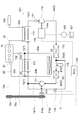
Classifications
-
- F—MECHANICAL ENGINEERING; LIGHTING; HEATING; WEAPONS; BLASTING
- F01—MACHINES OR ENGINES IN GENERAL; ENGINE PLANTS IN GENERAL; STEAM ENGINES
- F01K—STEAM ENGINE PLANTS; STEAM ACCUMULATORS; ENGINE PLANTS NOT OTHERWISE PROVIDED FOR; ENGINES USING SPECIAL WORKING FLUIDS OR CYCLES
- F01K23/00—Plants characterised by more than one engine delivering power external to the plant, the engines being driven by different fluids
- F01K23/02—Plants characterised by more than one engine delivering power external to the plant, the engines being driven by different fluids the engine cycles being thermally coupled
- F01K23/06—Plants characterised by more than one engine delivering power external to the plant, the engines being driven by different fluids the engine cycles being thermally coupled combustion heat from one cycle heating the fluid in another cycle
- F01K23/065—Plants characterised by more than one engine delivering power external to the plant, the engines being driven by different fluids the engine cycles being thermally coupled combustion heat from one cycle heating the fluid in another cycle the combustion taking place in an internal combustion piston engine, e.g. a diesel engine
-
- F—MECHANICAL ENGINEERING; LIGHTING; HEATING; WEAPONS; BLASTING
- F01—MACHINES OR ENGINES IN GENERAL; ENGINE PLANTS IN GENERAL; STEAM ENGINES
- F01K—STEAM ENGINE PLANTS; STEAM ACCUMULATORS; ENGINE PLANTS NOT OTHERWISE PROVIDED FOR; ENGINES USING SPECIAL WORKING FLUIDS OR CYCLES
- F01K15/00—Adaptations of plants for special use
- F01K15/02—Adaptations of plants for special use for driving vehicles, e.g. locomotives
-
- F—MECHANICAL ENGINEERING; LIGHTING; HEATING; WEAPONS; BLASTING
- F01—MACHINES OR ENGINES IN GENERAL; ENGINE PLANTS IN GENERAL; STEAM ENGINES
- F01K—STEAM ENGINE PLANTS; STEAM ACCUMULATORS; ENGINE PLANTS NOT OTHERWISE PROVIDED FOR; ENGINES USING SPECIAL WORKING FLUIDS OR CYCLES
- F01K25/00—Plants or engines characterised by use of special working fluids, not otherwise provided for; Plants operating in closed cycles and not otherwise provided for
- F01K25/08—Plants or engines characterised by use of special working fluids, not otherwise provided for; Plants operating in closed cycles and not otherwise provided for using special vapours
- F01K25/10—Plants or engines characterised by use of special working fluids, not otherwise provided for; Plants operating in closed cycles and not otherwise provided for using special vapours the vapours being cold, e.g. ammonia, carbon dioxide, ether
-
- F—MECHANICAL ENGINEERING; LIGHTING; HEATING; WEAPONS; BLASTING
- F01—MACHINES OR ENGINES IN GENERAL; ENGINE PLANTS IN GENERAL; STEAM ENGINES
- F01N—GAS-FLOW SILENCERS OR EXHAUST APPARATUS FOR MACHINES OR ENGINES IN GENERAL; GAS-FLOW SILENCERS OR EXHAUST APPARATUS FOR INTERNAL-COMBUSTION ENGINES
- F01N5/00—Exhaust or silencing apparatus combined or associated with devices profiting by exhaust energy
- F01N5/02—Exhaust or silencing apparatus combined or associated with devices profiting by exhaust energy the devices using heat
Definitions
- This invention relates to the Rankine cycle.
- the Rankine cycle is a heat exchanger that superheats the working fluid by exchanging heat between the heat medium containing heat exhausted from the internal combustion engine and the working fluid, and obtains power by expanding the working fluid in the superheated steam state.
- the expander rotates a rotating body such as a turbine by expanding the working fluid, thereby converting the energy at the time of expansion of the working fluid into a rotational driving force, and the converted rotational driving force is used as a generator or the like. To be transmitted as power.
- Patent Document 1 a refrigerant pump and a first heat exchanger that exchange heat between the refrigerant and the cooling water (heat medium) of the internal combustion engine in the middle of a flow path for sending the refrigerant (working fluid) to the expander, and the refrigerant And the Rankine cycle which has arrange
- the refrigerant pump is operated when the cooling water temperature reaches 90 ° C. or higher, and the refrigerant circulating through the Rankine cycle thereby exchanges heat with cooling water of about 90 to 100 ° C. in the first heat exchanger.
- the second heat exchanger exchanges heat with the exhaust gas of 300 to 400 ° C. to become superheated steam of about 120 to 130 ° C. and flows into the expander.
- the amount of heat absorbed by the refrigerant through heat exchange with the heat medium made of cooling water or exhaust gas varies greatly depending on the pressure of the refrigerant even if the temperature of the heat medium is constant. Furthermore, the amount of heat absorbed by the refrigerant in heat exchange varies depending on the temperature of the heat medium even if the pressure of the refrigerant is constant. Therefore, the amount of heat absorbed by the refrigerant through heat exchange with the heat medium is affected by the pressure of the refrigerant and the temperature of the heat medium.
- This invention was made in order to solve such a problem, and Rankine cycle which aims at increase of the heat absorption amount of the refrigerant
- the purpose is to provide.
- a Rankine cycle includes a first heat exchanger that exchanges heat between a working fluid and a low-temperature side heat medium in a circulation path of the working fluid, Heat exchanger for exchanging heat, fluid expander for generating driving force by expanding the working fluid, condenser for condensing the working fluid, and fluid pumping device for transferring the working fluid to the first heat exchanger
- the pressure detector that detects the pressure of the working fluid at the inlet of the fluid expander
- the temperature detector that detects the temperature of the low-temperature heat medium flowing into the first heat exchanger
- the fluid A pressure adjusting means for adjusting the pressure of the working fluid at the inlet of the expander; and a control device for controlling the pressure adjusting means.
- the control device operates according to the temperature of the low temperature side heat medium detected by the temperature detector. Saturated steam of fluid Calculating a target pressure to be under pressure or, as the pressure detected by the pressure detector reaches the target pressure,
- the heat absorption amount of the working fluid in the first heat exchanger can be increased by controlling the temperature of the heat medium in association with the pressure of the working fluid.
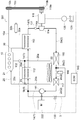
- Rankine cycle 101 according to an embodiment of the present invention and the configuration around it will be described.
- a vehicle (not shown) including an engine 10 includes a Rankine cycle 101.
- the Rankine cycle 101 forms a circulation path that sequentially connects the pump 111, the cooling water boiler 112, the waste gas boiler 113, the expander 114, the condenser 115, the receiver 116, and the subcooler 117, and the refrigerant that is the working fluid flows. It is supposed to be.
- the pump 111 is operated to pump a fluid, and in this embodiment, the liquid is pumped.
- the pump 111 shares its drive shaft 119 with the expander 114.
- a pulley 119b is coupled to the drive shaft 119 via an electromagnetic clutch 119a.
- the pulley 119b is connected to an engine pulley 10b connected to an engine drive shaft 10a extending from the engine 10 by a drive belt 10c.
- the electromagnetic clutch 119a can connect or disconnect the drive shaft 119 and the pulley 119b, and is electrically connected to the ECU 140, which is a vehicle control device, to control the connecting / disconnecting operation thereof. For this reason, the rotation speed of the pump 111 depends on the rotation speed of the engine 10 or the expander 114.
- the pump 111 constitutes a fluid pressure feeding device
- the engine drive shaft 10a, the engine pulley 10b, the drive belt 10c, the pulley 119b, the electromagnetic clutch 119a, and the drive shaft 119 constitute a power transmission mechanism.
- the discharge port on the downstream side of the pump 111 communicates with the refrigerant inlet of the cooling water boiler 112 via the flow path portions 1a and 1b.
- the cooling water for cooling the engine that flows through the cooling water circuit 20 of the engine 10 and the refrigerant flow and exchange heat with each other, whereby the refrigerant can be heated.
- the cooling water constitutes a low temperature side heat medium
- the cooling water boiler 112 constitutes a first heat exchanger.
- the cooling water circuit 20 extends from the engine 10 and is connected to a water pump 21 integral with the engine 10 to form a circulation flow path, a return-side water flow path 20b and 20c, and a feed-side water flow path 20a. And a radiator 22 provided between the return side water flow path 20b and a branch water flow path 20d branched from the middle of the feed side water flow path 20a and connected to the connecting portion of the return side water flow paths 20b and 20c. . And the cooling water boiler 112 is provided in the middle of the branched water flow path 20d.
- the water pump 21 sucks the cooling water from the return side water flow path 20 c and circulates the inside of the engine 10, and then flows out into the feed side water flow path 20 a to circulate the cooling water circuit 20.
- the radiator 22 cools the cooling water by exchanging heat between the cooling water flowing inside and the surrounding air.
- a thermostat 23 is provided at a connection portion between the branch water channel 20d and the return side water channels 20b and 20c.
- the thermostat 23 operates corresponding to the temperature of the cooling water.
- the return side water flow path 20b is used to raise the temperature of the low-temperature cooling water.
- the branch water flow path 20d is communicated with the return-side water flow path 20c, and the cooling water is not circulated to the radiator 22.
- the thermostat 23 communicates between the return-side water flow paths 20b and 20c and distributes the cooling water to the radiator 22 in order to cool the cooling water.
- the thermostat 23 gives priority to cooling of the cooling water, and therefore between the branch water channel 20d and the return side water channel 20c.
- the radiator 22 is circulated through all the cooling water.
- the refrigerant outlet of the cooling water boiler 112 communicates with the refrigerant inlet of the waste gas boiler 113 via the flow path portion 1c.
- the refrigerant flowing out of the cooling water boiler 112 and the exhaust gas of the exhaust system 30 of the engine 10 circulate and exchange heat with each other, whereby the refrigerant can be heated.
- the waste gas boiler 113 is provided in the middle of the exhaust flow path 30a which connects the engine 10 in the exhaust system 30 to the muffler 30b.
- the exhaust gas constitutes a high temperature side heat medium
- the waste gas boiler 113 constitutes a second heat exchanger.
- the refrigerant outlet of the waste gas boiler 113 communicates with the inlet of the expander 114 that is a fluid expander via the flow path portion 1d.
- the expander 114 rotates the drive shaft 119 together with a rotating body such as a turbine by expanding the high-temperature and high-pressure refrigerant after being heated by the cooling water boiler 112 and the waste gas boiler 113, thereby rotating driving force. It is a fluid device that gets the work by.
- an alternator 118 having a power generation function is provided between the expander 114 and the pump 111, and the alternator 118 shares a drive shaft 119.
- the rotational driving force generated by the expander 114 can integrally drive the alternator 118 and the pump 111 via the driving shaft 119, and the driving force of the pump 111 applied by the engine 10 is the driving shaft.
- the alternator 118 and the expander 114 can be integrally driven via 119.
- the flow path portions 1a, 1b, 1c, and 1d constitute the first flow path 1 that is a high-pressure side flow path of the refrigerant.
- the alternator 118 is electrically connected to the converter 120, and the converter 120 is electrically connected to the battery 121.
- the alternator 118 When the expander 114 rotates and drives the drive shaft 119, the alternator 118 generates an alternating current and sends it to the converter 120.
- the converter 120 converts the sent alternating current into a direct current and supplies it to the battery 121 for charging.
- the outlet of the expander 114 communicates with the inlet of the capacitor 115 through the flow path portion 2a.
- the refrigerant flows and exchanges heat with the air around the condenser 115, whereby the refrigerant can be cooled and condensed.
- the capacitor 115 constitutes a condenser.
- the outlet of the capacitor 115 communicates with the inlet of the receiver 116 via the flow path portion 2b, and further, the outlet of the receiver 116 communicates with the inlet of the subcooler 117 via the flow path portion 2c.
- the receiver 116 is a gas-liquid separator that includes a liquid refrigerant therein, and removes vapor components, moisture, foreign matters, and the like of the refrigerant contained in the refrigerant. Inside the subcooler 117, the liquid refrigerant sent from the receiver 116 flows and exchanges heat with the air around the subcooler 117, whereby the refrigerant can be supercooled.
- the outlet of the subcooler 117 communicates with the suction port of the pump 111 via the flow path portion 2d, and the refrigerant flowing out of the subcooler 117 is sucked by the pump 111 and pumped again to circulate through the Rankine cycle 101.
- the flow path portions 2a, 2b, 2c, and 2d constitute the second flow path 2 that is a low pressure side flow path of the refrigerant.
- the Rankine cycle 101 also includes a bypass channel 3 that communicates the channel portion 1 a of the first channel 1 with the second channel 2.
- a bypass channel 3 that communicates the channel portion 1 a of the first channel 1 with the second channel 2.
- one end of the bypass channel 3 is connected to the connecting portion of the channel 1a and the channel 1b of the first channel 1, and the other end of the bypass channel 3 is The second channel 2 is connected to the channel 2b.
- the Rankine cycle 101 includes a flow rate adjustment valve 130 that can open or close the bypass flow path 3 and adjust the cross-sectional area of the bypass flow path 3 in the middle of the bypass flow path 3. Yes.
- the flow rate adjusting valve 130 is electrically connected to the ECU 140 and its operation is controlled.
- the bypass flow path 3 and the flow rate adjusting valve 130 constitute a pressure adjusting means.
- the Rankine cycle 101 includes a pressure sensor 131 that detects the pressure of the refrigerant flowing through the flow path portion 1d in the vicinity of the inlet of the expander 114 in the flow path portion 1d of the first flow path 1.
- the pressure sensor 131 detects the pressure of the refrigerant at the inlet of the expander 114, that is, the pressure of the refrigerant flowing into the expander 114, and sends the detected refrigerant pressure information to the electrically connected ECU 140.
- the pressure of the refrigerant is the same between the flow path portions regardless of whether the flow rate adjustment valve 130 is opened or closed. It may be provided in any of 1a to 1c.
- the pressure sensor 131 constitutes a pressure detector.
- the Rankine cycle 101 includes a cooling water temperature sensor 132 that detects the temperature of the circulating cooling water between the engine 10 and the branch water passage 20d in the feed water passage 20a of the cooling water circuit 20.
- the cooling water temperature sensor 132 detects the temperature of the cooling water that is sent out from the engine 10 and before the heat exchange action is received by the cooling water boiler 112 or the radiator 22, and the temperature of the cooling water detected by the electrically connected ECU 140. Send information.
- the cooling water temperature sensor 132 constitutes a temperature detector.
- the water pump 21 is also operated to pump the cooling water.
- the cooling water pumped out from the engine 10 circulates through the cooling water circuit 20 and returns to the engine 10 again.
- the thermostat 23 shuts off the communication between the return side water flow paths 20b and 20c so that the cooling water is not cooled by the radiator 22 until the cooling water reaches the first operating temperature (90 ° C.) or higher.
- the branch water channel 20d is communicated with the return side water channel 20c.
- the cooling water exchanges heat with the refrigerant in the cooling water boiler 112.
- exhaust gas is discharged from the started engine 10 to the exhaust system 30.
- the discharged exhaust gas flows through the waste gas boiler 113 during the distribution process, and is then discharged from the muffler 30b to the outside of the vehicle.
- the exhaust gas exchanges heat with the refrigerant in the waste gas boiler 113.
- ECU 140 connects electromagnetic clutch 119a.
- the rotational driving force of the engine 10 is transmitted to the drive shaft 119 via the engine drive shaft 10a, the engine pulley 10b, the drive belt 10c, the pulley 119b, and the electromagnetic clutch 119a, whereby the drive shaft 119 is pumped.
- 111, the alternator 118, and the expander 114 are driven integrally.
- the driven pump 111 pumps the refrigerant in the liquid state toward the cooling water boiler 112, and the driven expander 114 rotates the rotating body such as a turbine, thereby causing the flow path of the first flow path 1 to flow.
- the refrigerant in the part 1 d is depressurized and sent to the flow path part 2 a of the second flow path 2.
- the refrigerant is subjected to adiabatic pressurization by being pumped by the pump 111.
- the temperature of the cooling water is assumed to be a temperature Tw1 (in this embodiment, 80 ° C.).
- Tw1 in this embodiment, 80 ° C.
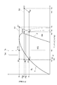
- FIG. 2 the state change of the refrigerant in the circulation process of the Rankine cycle 101 is shown on the ph diagram of the refrigerant.
- the ph diagram has an orthogonal coordinate system in which the vertical axis represents the refrigerant pressure (unit: MPa) and the horizontal axis represents the refrigerant enthalpy (unit: kJ / kg). Further, the region where the refrigerant is in the supercooled liquid state is indicated by the supercooled liquid region SL, the region where the refrigerant is in the wet steam state is indicated by the wet steam region WS, and the region where the refrigerant is in the superheated steam state is the superheated steam region. It is indicated by SS. A saturated liquid line ⁇ is shown at the boundary between the supercooled liquid region SL and the wet steam region WS, and a dry saturated vapor line ⁇ is shown at the boundary between the wet steam region WS and the superheated steam region SS.
- the refrigerant state changes along the first cycle S1 having a trapezoidal shape with the points A1, B1, C1, and D1 as vertices. proceed.
- the refrigerant raises its pressure from pressure P 1 to pressure P 2 and increases its temperature, and changes from the point A1 to the point B1.
- the refrigerant increases its enthalpy from ha to hb.
- the state of the refrigerant between point A1 and point B1 maintains a liquid state (supercooled liquid state) in the supercooled liquid region SL.
- the refrigerant changes from a point B1 to a point P 2 Te (a point between the point B1 and the point C1 in the first cycle S1), and increases its enthalpy to he.
- the point P 2 Te is an intersection of the isobaric line of the pressure P 2 and the isotherm of the temperature Te.
- the refrigerant in the state between point B1 of the point P 2 Te will remain liquid in the supercooled liquid region SL (supercooled liquid state).
- the refrigerant that has flowed out of the cooling water boiler 112 passes through the flow path portion 1c, flows into the waste gas boiler 113, is heated at an equal pressure by exchanging heat with the exhaust gas that circulates therein, and rises in temperature. It flows out as high-temperature and high-pressure superheated steam.
- the refrigerant is further raised the temperature to maintain the pressure in the pressure P 2.
- the refrigerant changes from the point P 2 Te to the state of the point C1, and increases its enthalpy to hc. Note that the state of the refrigerant between point P 2 Te and point C1 changes from the liquid state in the supercooled liquid region SL to the superheated steam state in the superheated steam region SS.
- the high-temperature and high-pressure refrigerant in the superheated steam state that has flowed out of the waste gas boiler 113 passes through the flow path portion 1 d and flows into the expander 114.
- the refrigerant adiabatically expands using the refrigerant pressure difference between the upstream-side channel portion 1 d and the downstream-side channel portion 2 a, and then flows out in a high-temperature and low-pressure superheated steam state.
- the expansion energy of the refrigerant is converted into rotational energy as regenerative energy and transmitted to the drive shaft 119.
- the refrigerant expands to reduce the pressure from the pressure P 2 to the pressure P 1 and to decrease the temperature. At this time, the refrigerant changes from the point C1 to the point D1, and reduces its enthalpy to hd. In addition, the state of the refrigerant
- the regenerative energy transmitted to the drive shaft 119 is not only applied as a rotational drive force to the alternator 118 and the pump 111 but also transmitted to the engine 10 to assist the rotational drive.
- Alternator 118 is operated by an applied rotational driving force to generate an alternating current, and the generated alternating current is converted into a direct current by converter 120 and then charged to battery 121.
- the superheated vapor refrigerant flowing out of the expander 114 passes through the flow path portion 2a and flows into the condenser 115, where it is cooled at an equal pressure by exchanging heat with the surrounding air, that is, outside air, and condensed. And flows out in a liquid state.
- the isobaric cooling step by the capacitor 115 the refrigerant lowers its temperature, to maintain the pressure in the pressure P 1.
- the refrigerant changes from a point D1 to a point F1 (a point between the point D1 and the point A1 in the first cycle S1), and reduces the enthalpy to hf. Note that the state of the refrigerant between the point D1 and the point F1 changes from the superheated steam state in the superheated steam region SS to the saturated liquid state.
- the liquid refrigerant flowing out of the condenser 115 passes through the flow path portion 2b and flows into the receiver 116, passes through the liquid refrigerant stored inside the receiver 116, and flows out into the flow path portion 2c.
- the refrigerant passes through the receiver 116, the vapor component, moisture, foreign matter, and the like of the refrigerant contained are removed.
- the refrigerant flowing out of the receiver 116 passes through the flow path portion 2c and flows into the subcooler 117, where it is further cooled at the same pressure (supercooled) by exchanging heat with the outside air in the subcooler 117. And flows out to the flow path portion 2d. Further, the refrigerant in the flow path portion 2d is sucked into the pump 111 and pumped again, and circulates through the Rankine cycle 101.
- the refrigerant In the isobaric cooling step by the sub-cooler 117, the refrigerant, the temperature further lowers, the pressure is maintained at the pressure P 1.
- the refrigerant changes from the point F1 to the state of the point A1, and reduces the enthalpy to ha.
- the state of the refrigerant between point F1 and point A1 changes from the saturated liquid state to the supercooled liquid state in the supercooled liquid region SL.
- the refrigerant increases the pressure from the pressure P 1 to the pressure P 3 and increases the temperature, and further increases the enthalpy from ha to hb2,
- the state changes from point A1 to point B2.
- the state of the refrigerant between point A1 and point B2 maintains a liquid state (supercooled liquid state).
- the refrigerant temperature is raised to a temperature Te by heat exchange with the cooling water temperature Tw1, to maintain the pressure in the pressure P 3.
- the refrigerant, from the point B2, and change in the state of (a point between point B2 and point C2 in the second cycle S2) P 3 Te point of the pressure P 3 and the temperature Te, the enthalpy in he2 increase.
- the pressure P 3 has a saturated vapor pressure less than Pse of the refrigerant in the temperature Te, thereby, the point P 3 Te, is located within the superheated steam region SS. For this reason, the state of the refrigerant between point B2 and point P 3 Te changes from the liquid state to the superheated vapor state through the wet vapor state, and the refrigerant includes latent heat of vaporization.
- the amount of heat absorbed by the refrigerant from the cooling water in the cooling water boiler 112 is obtained by multiplying the flow rate of the refrigerant in the cooling water boiler 112 by the amount of change in the enthalpy of the refrigerant before and after heat exchange. It is proportional to the pressure of the refrigerant in the boiler 112 multiplied by the amount of change in the enthalpy of the refrigerant before and after heat exchange. For this reason, the heat absorption amount of the refrigerant in the cooling water boiler 112 is also greatly increased in the second cycle S2 as compared with the first cycle S1.
- the refrigerant flowing out from the cooling water boiler 112 performs exhaust gas heat exchanger in the waste gas boiler 113, the refrigerant, the point P to maintain the pressure with further raise its temperature to a pressure P 3 3 Change from Te to point C2 and increase its enthalpy to hc2.
- the state of the refrigerant between point P 3 Te and point C2 maintains the superheated steam state.
- the adiabatic expansion process in which the refrigerant flowing out from the waste gas boiler 113 is expanded in expander 114, the refrigerant, from the point C2 to lower the temperature with decreasing pressure P 1 of the pressure from the pressure P 3 of the point D2 state And the enthalpy is reduced to hd2.
- coolant between the point C2 and the point D2 maintains a superheated steam state.
- the refrigerant pressure point F1 (first from point D2 and maintained at a pressure P 1 along with lowering the temperature
- the state changes to the state between the point D2 and the point A1 in the two cycles S2, and the enthalpy is reduced to hf.
- the state of the refrigerant between point D2 and point F1 changes from the superheated steam state to the saturated liquid state.
- the isobaric cooling step in which the refrigerant flowing out from the capacitor 115 performs outside air exchanges heat with sub-cooler 117 after passing through the receiver 116, the refrigerant in the point to maintain pressure in the pressure P 1 with further lowering the temperature
- the state changes from F1 to the state of point A1, and the enthalpy is reduced to ha.
- the state of the refrigerant between point F1 and point A1 changes from the saturated liquid state to the supercooled liquid state.
- the enthalpy ⁇ he2 obtained from the coolant by the cooling water boiler 112 in the second cycle S2 is significantly increased with respect to the enthalpy ⁇ he obtained from the coolant by the cooling water boiler 112 in the first cycle S1.
- the amount of heat absorbed by the coolant in the cooling water boiler 112 is also greatly increased in the second cycle S2 than in the first cycle S1.
- the increase in the amount of heat absorbed by the cooling water boiler 112 is caused by changing the refrigerant pressure in the cooling water boiler 112 (that is, the refrigerant pressure in the flow path portions 1a to 1d of the first flow path 1) and the refrigerant pressure at the temperature Te. This can be achieved by controlling the saturated vapor pressure Pse or less.
- the pressure of the refrigerant in the cooling water boiler 112 to a high pressure so as to be as close as possible to the saturated vapor pressure Pse, the upstream side flow passage portion 1d and the downstream side flow passage portion 2a. It is possible to ensure a high differential pressure of the refrigerant between the two and the amount of regenerative energy obtained in the expander 114.
- the ECU 140 sets the pressure of the refrigerant in the cooling water boiler 112, that is, the first pressure.
- the target pressure of the refrigerant pressure in the flow path portions 1a to 1d of the single flow path 1 is set based on the saturation vapor pressure Pse of the refrigerant at the temperature Te, and the flow pressure adjusting valve 130 is controlled so that the refrigerant pressure is changed to the target pressure.
- the ECU 140 sets the target pressure of the refrigerant based on the temperature Tw of the cooling water before heat exchange and the saturated vapor pressure Pse indicated by the refrigerant that has reached the temperature Te by exchanging heat with the cooling water. .
- the ECU 140 uses the coolant temperature detected by the coolant temperature sensor 132 and the refrigerant temperature and saturated vapor pressure stored in advance to make the detected coolant temperature the coolant temperature.
- the refrigerant that is, the saturated vapor pressure of the refrigerant corresponding to the cooling water temperature. Further, the ECU 140 sets a pressure obtained by reducing a predetermined amount of pressure ⁇ p from the calculated saturated vapor pressure as the target pressure of the refrigerant in the flow path portions 1a to 1d of the first flow path 1.
- This pressure ⁇ p is caused by heat loss due to the heat exchange capacity of the cooling water boiler 112, the thermal conductivity of the material, etc., and the cooling water temperature Tw before the heat exchange in the cooling water boiler 112 and the refrigerant temperature Te after the heat exchange. (Refer to FIG. 2) and preset in correspondence with the temperature difference ⁇ Te between them and stored in the ECU 140.
- ECU140 controls the opening degree of the flow regulating valve 130, The flow rate of the refrigerant flowing into the cooling water boiler 112 is changed, and control is performed so that the detected pressure of the pressure sensor 131 in the flow path portion 1d becomes the target pressure. That is, when the detected pressure of the pressure sensor 131 is lower than the target pressure, the ECU 140 decreases the opening degree of the flow rate adjustment valve 130 and increases the refrigerant flow rate of the flow path unit 1d, thereby increasing the flow rate of the flow path unit 1d. Increase refrigerant pressure.
- the ECU 140 increases the opening of the flow rate adjustment valve 130 to decrease the refrigerant flow rate of the flow path unit 1d, thereby reducing the flow rate of the flow path unit 1d. Reduce refrigerant pressure.
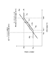
- the target pressure calculation method is changed depending on the temperature region of the cooling water, and the relationship between the target pressure and the cooling water temperature detected by the cooling water temperature sensor 132 in this case is shown in the graph of FIG. Is shown in FIG.
- the graph of FIG. 3 has an orthogonal coordinate system in which the vertical axis is the refrigerant pressure (unit is MPa) and the horizontal axis is the cooling water temperature (unit is ° C.).
- the relationship between the target pressure and the cooling water temperature is shown by a target pressure graph Pt which is a solid line graph, and the relationship between the saturated vapor pressure of the refrigerant corresponding to the cooling water temperature and the cooling water temperature is indicated by a one-dot chain line.
- the target saturated vapor pressure graph Pst is shown.
- the target pressure graph Pt the portion Pta corresponding to the range of the coolant temperature TwL1 to TwH is equal to the target saturation vapor pressure graph Pst in the negative direction of the refrigerant pressure (vertical axis negative direction).
- the target saturated vapor pressure graph Pst is translated by the temperature ⁇ Te in the positive direction of the cooling water temperature (the positive direction of the horizontal axis) in the present embodiment. Identical. Therefore, the target pressure of the part Pta is set by the above-described calculation method.
- the target pressure at the part Pta is lower than the saturated vapor pressure of the refrigerant corresponding to the cooling water temperature by a predetermined pressure ⁇ p, and increases with an increase in the cooling water temperature and decreases in the cooling water temperature. It decreases with this, and is proportional to the cooling water temperature.
- the ECU 140 adjusts the flow rate so that the detected pressure of the pressure sensor 131 becomes the target pressure on the target pressure graph Pt when the coolant temperature detected by the coolant temperature sensor 132 is in the range of the temperature TwL1 to TwH.
- the valve 130 is controlled.
- the temperature TwL1 constitutes a first predetermined temperature
- the temperature TwH constitutes a second predetermined temperature.
- a portion Ptb corresponding to a range lower than the cooling water temperature TwL1 is a horizontal straight line with the target pressure being constant, with the saturated vapor pressure PsL of the refrigerant at the temperature TwL as the target pressure. is there.
- the temperature TwL is a temperature set in advance as a low cooling water temperature that reduces the efficiency of the engine 10 when the temperature is lower than the temperature TwL, and is set to 60 ° C. in the present embodiment.
- temperature TwL1 is the cooling water temperature which hits the intersection of the site
- the temperature TwL1 is also a temperature obtained by adding the temperature ⁇ Te to the temperature TwL.
- the ECU 140 controls the flow rate adjustment valve 130 so that the pressure detected by the pressure sensor 131 does not become less than the saturated vapor pressure PsL of the refrigerant at the temperature TwL.
- the refrigerant having a pressure equal to or higher than the saturated vapor pressure PsL of the refrigerant at the temperature TwL (60 ° C.) always does not include latent heat of vaporization even if heat exchange is performed with the cooling water below the temperature TwL.
- the amount of heat absorbed from can be kept low. Therefore, the cooling water can be controlled so as not to be lower than the temperature TwL.
- the cooling water temperature varies as follows. .
- the cooling water temperature decreases and falls below the saturation temperature TwL of the refrigerant, the amount of heat that the refrigerant can absorb from the cooling water at the moment when the cooling water falls is greatly reduced, so that the cooling water reduces the amount of heat released to the refrigerant.
- the temperature drop stops and the temperature rises.
- the cooling water temperature exceeds the refrigerant saturation temperature TwL due to the temperature rise, the amount of heat absorbed by the refrigerant increases and the cooling water temperature decreases again.
- the cooling water is controlled so as not to drop below the refrigerant saturation temperature TwL.
- a part Ptc corresponding to the range exceeding the cooling water temperature TwH is a horizontal straight line that keeps the target pressure constant at the refrigerant target pressure PH corresponding to the cooling water temperature TwH.
- the cooling water temperature TwH is the temperature of the cooling water whose saturation vapor pressure corresponds to the upper limit pressure PH set for the piping of the first flow path 1 and the expander 114, and in this embodiment, the thermostat 23 starts to open. It is the same as the first operating temperature (90 ° C.).
- the ECU 140 controls the flow rate adjustment valve 130 so that the pressure detected by the pressure sensor 131 becomes the target pressure PH. Thereby, it can prevent that the 1st flow path 1 and the expander 114 are exposed to abnormally high pressure.
- the ECU 140 is described so as to calculate the target pressure by calculation.
- the graph of FIG. 3 may be stored as a map, and the target pressure may be calculated based on the stored map.
- the cooling water boiler 112 that exchanges heat between the refrigerant and the cooling water
- the waste gas boiler 113 that exchanges heat between the refrigerant and the exhaust gas.
- An expander 114 that generates a driving force by expanding the refrigerant, a condenser 115 that condenses the refrigerant, and a pump 111 that transfers the refrigerant to the cooling water boiler 112 are sequentially provided.
- the Rankine cycle 101 includes a pressure sensor 131 that detects the pressure of the refrigerant at the inlet of the expander 114, a cooling water temperature sensor 132 that detects the temperature of the cooling water flowing into the cooling water boiler 112, and a refrigerant at the inlet of the expander 114.
- the bypass flow path 3 and the flow rate adjusting valve 130 for adjusting the pressure of the ECU and the ECU 140 for controlling the flow rate adjusting valve 130 are provided.
- the ECU 140 calculates a target pressure that is equal to or lower than the saturated vapor pressure of the refrigerant corresponding to the temperature of the cooling water detected by the cooling water temperature sensor 132, and the flow rate so that the pressure detected by the pressure sensor 131 becomes the target pressure.
- the regulating valve 130 is controlled.
- the bypass flow path 3 and the flow rate adjustment valve 130 adjust the refrigerant pressure at the inlet of the expander 114 by adjusting the amount of refrigerant flowing into the cooling water boiler 112.
- the pressure of the refrigerant that exchanges heat with the cooling water in the cooling water boiler 112 is controlled to be a target pressure that is equal to or lower than the saturated vapor pressure of the refrigerant corresponding to the temperature of the cooling water.
- the amount of heat of the refrigerant after heat exchange with the cooling water is a large amount of heat including the latent heat of evaporation.
- the pressure of the refrigerant is controlled to be larger than the saturated vapor pressure of the refrigerant corresponding to the temperature of the cooling water, the amount of heat of the refrigerant after heat exchange with the cooling water becomes a small amount of heat not including the latent heat of evaporation. . Therefore, Rankine cycle 101 makes it possible to increase the amount of heat absorbed by the refrigerant from the cooling water in cooling water boiler 112 by controlling the temperature of the cooling water and the pressure of the refrigerant in association with each other as described above.
- the target pressure of the refrigerant is set to increase in accordance with the saturated vapor pressure of the refrigerant corresponding to the cooling water temperature, which rises as the cooling water temperature rises. Therefore, the coolant flow rate of the cooling water boiler 112 can be increased as the cooling water temperature increases. Therefore, in the cooling water boiler 112, the heat absorption amount of the refrigerant from the cooling water can be increased in accordance with the increase in the cooling water temperature, and the temperature increase of the cooling water can be suppressed.
- the bypass flow path 3 communicates the flow path portion 1 a of the refrigerant from the pump 111 to the cooling water boiler 112 to the second flow path 2 of the refrigerant from the expander 114 to the pump 111.
- the Rankine cycle 101 makes it possible to efficiently use the thermal energy acquired by the cooling water boiler 112 and the waste gas boiler 113.
- the bypass flow path 3 through which the refrigerant having a high density before being heated flows the necessary flow rate of the refrigerant can be secured even if the diameter and the flow rate adjustment valve 130 are small.
- the adjustment valve 130 can be downsized.
- the bypass flow path 3 connects the flow path section 1 a to the flow path section 2 b between the condenser 115 and the pump 111 in the second flow path 2 of the refrigerant from the expander 114 toward the pump 111. To do. As a result, the refrigerant flowing through the bypass flow path 3 flows downstream of the condenser 115, so that the pressure loss in the condenser 115 is not increased, and the refrigerant pressure in the flow path portion 2a between the expander 114 and the condenser 115 is increased. Can be suppressed.
- the differential pressure of the refrigerant between the upstream-side channel portion 1d and the downstream-side channel portion 2a of the expander 114 can be ensured high, sufficient regenerative energy obtained by the expander 114 is ensured. It becomes possible to do.
- the bypass flow path 3 connected between the condenser 115 and the subcooler 117 is pump cavitation (refrigeration of refrigerant) that occurs when the flow path section 1a is bypassed to the flow path section 2d between the subcooler 117 and the pump 111. ) Can be prevented.
- the bypass flow path 3 connected between the condenser 115 and the pump 111 is a refrigerant flowing into the condenser 115 that occurs when the flow path section 1a is bypassed to the flow path section 2a between the expander 114 and the condenser 115. It is possible to prevent a decrease in the amount of heat released from the capacitor 115 due to a decrease in the temperature of the inflowing refrigerant. This decrease in the heat dissipation amount in the capacitor 115 increases the pressure of the second flow path 2, and causes the refrigerant differential pressure between the upstream flow path section 1 d and the downstream flow path section 2 a of the expander 114. Therefore, the regenerative energy obtained by the expander 114 is reduced.
- PsL saturated vapor pressure of refrigerant at temperature TwL
- TwL1 TwL [60 ° C. at the cooling water temperature at which the efficiency of the engine 10 decreases) + ⁇ Te)
- TwL1 TwL [60 ° C. at the cooling water temperature at which the efficiency of the engine 10 decreases) + ⁇ Te
- the ECU 140 sets the target pressure to the temperature TwL ( The flow rate adjustment valve 130 is controlled so that the saturated vapor pressure PsL of the refrigerant at 60 ° C. and the detected pressure of the pressure sensor 131 is equal to or higher than the saturated vapor pressure PsL or the saturated vapor pressure PsL. It is not something.
- the ECU 140 sets the target pressure so as to increase from the saturated vapor pressure PsL of the refrigerant at the temperature TwL as the cooling water temperature decreases.
- the flow rate adjustment valve 130 may be controlled so that the detected pressure becomes the target pressure. Even with such control, the refrigerant has a pressure larger than the saturated vapor pressure of the refrigerant corresponding to the cooling water temperature, so that the latent heat of vaporization is converted into the amount of heat absorbed from the cooling water by heat exchange in the cooling water boiler 112. It can be excluded.
- the ECU 140 does not include control for changing the setting of the target pressure related to the cooling water temperature with the first predetermined temperature TwL1 as a boundary, and the target pressure of the part Ptb of the target pressure graph Pt is changed to the part Pta.
- the target pressure based on the saturated vapor pressure of the refrigerant corresponding to the cooling water temperature may be used.
- the ECU 140 includes the refrigerant saturated vapor pressure PsL corresponding to the coolant temperature TwL as a lower limit value of the target pressure, and adjusts the flow rate so that the pressure detected by the pressure sensor 131 does not fall below the saturated vapor pressure PsL.
- the valve 130 may be controlled.
- the refrigerant has a pressure larger than the saturated vapor pressure of the refrigerant corresponding to the cooling water temperature, the amount of heat absorbed from the cooling water by heat exchange in the cooling water boiler 112 is reduced to the latent heat of evaporation. Can be kept low.
- the ECU 140 determines the saturation vapor pressure PsL of the refrigerant at the temperature TwL (60 ° C.).
- the flow rate adjustment valve 130 may be controlled so that a constant pressure larger than the target pressure is set as the target pressure and the detected pressure of the pressure sensor 131 becomes the target pressure. Even with such control, the refrigerant can keep the amount of heat absorbed from the cooling water through heat exchange in the cooling water boiler 112 low without including latent heat of evaporation.
- the ECU 140 does not include control for changing the setting of the target pressure related to the cooling water temperature with the second predetermined temperature TwH (90 ° C.) as a boundary, and the target pressure of the part Ptc of the target pressure graph Pt. May be set as the target pressure based on the saturated vapor pressure of the refrigerant corresponding to the cooling water temperature in the same manner as the portion Pta.
- the ECU 140 uses the flow rate adjustment valve 130 to adjust the cross-sectional area of the bypass flow path 3, thereby detecting the pressure detected by the pressure sensor 131 (the pressure of the refrigerant flowing into the cooling water boiler 112). ) Is adjusted, but is not limited to this.
- the alternator 118 of the embodiment may be a motor generator 218 having functions of a motor and a generator.
- the ECU 140 may adjust the number of rotations of the pump 111 and the expander 114 by controlling the number of rotations of the drive shaft 119 driven by the motor generator 218 to adjust the detected pressure of the pressure sensor 131.
- FIG. 6 the alternator 118 of the embodiment may be a motor generator 218 having functions of a motor and a generator.
- the pump 111 may be driven by the motor 322 without being connected to the engine 10.
- the ECU 140 can adjust the rotational speed of the pump 111 and the detected pressure of the pressure sensor 131 by controlling the rotational speed of the motor 322.
- the expander 114 connects the drive shaft 114a and the pulley 119b that is rotationally driven by the engine 10 via the electromagnetic clutch 119a, and the alternator 118 shares the drive shaft 114a.
- the pump 111 is not connected to the alternator 118 and the expander 114, but is connected only to the pulley 119b, and the expander 114 and the alternator 118 are connected to each other by the drive shaft 114a. It may be.
- the ECU 140 can adjust the rotation speed of the expander 114 and adjust the detected pressure of the pressure sensor 131 by changing the load of the alternator 118.
- the expander 114 may be capable of arbitrarily changing the suction volume. By changing the suction volume, the flow rate (volume flow rate) of the refrigerant transferred by the expander 114 is changed, and accordingly, the refrigerant pressure in the upstream flow path of the expander 114 is changed. The pressure can be adjusted.
- the bypass flow path 3 communicates the flow path portion 1a of the first flow path 1 with the flow path portion 2b of the second flow path 2, but is not limited thereto. Not.
- the bypass flow path 3 may be connected to any of the flow path portions 2a, 2c, and 2d with respect to the second flow path 2.
- the Rankine cycle 101 of the embodiment includes the two heat exchangers of the cooling water boiler 112 and the waste gas boiler 113, but is not limited thereto, and may include three or more.
- the Rankine cycle 101 may include a heat exchanger between the refrigerant of the air conditioner and the refrigerant of the Rankine cycle 101.
- the heat exchanger between the cooling water of the motor used in the hybrid car and the refrigerant of the Rankine cycle 101 is provided. You may have.
- a target pressure that is equal to or lower than the saturated vapor pressure of the refrigerant corresponding to the temperature of the heat medium of the heat exchanger selected from the heat exchanger and the cooling water boiler 112 is set, and the first flow path is set based on the target pressure.
- the pressure of one refrigerant By controlling the pressure of one refrigerant, the heat absorption amount of the refrigerant in the selected heat exchanger can be increased.
Landscapes
- Engineering & Computer Science (AREA)
- Chemical & Material Sciences (AREA)
- Combustion & Propulsion (AREA)
- Mechanical Engineering (AREA)
- General Engineering & Computer Science (AREA)
- Engine Equipment That Uses Special Cycles (AREA)
- Control Of Turbines (AREA)
Abstract
ランキンサイクル101は、冷媒の循環路に、冷却水ボイラ112、廃ガスボイラ113、膨張機114、コンデンサ115、及びポンプ111が順次設けられている。ランキンサイクル101は、膨張機114の入口の冷媒の圧力を検出する圧力センサ131と、冷却水ボイラ112に流入する冷却水の温度を検出する冷却水温度センサ132と、膨張機114の入口の冷媒の圧力を調節するバイパス流路3及び流量調整弁130と、流量調整弁130を制御するECU140とを備える。ECU140は、冷却水温度センサ132が検出する冷却水温度に対応する冷媒の飽和蒸気圧以下となる目標圧力を算出し、圧力センサ131が検出する圧力が目標圧力となるように流量調整弁130を制御する。
Description
この発明は、ランキンサイクルに関する。
車両の内燃機関から排出される熱を発電機等の動力に変換するランキンサイクルを利用した技術が開発されている。
ランキンサイクルは、内燃機関から排出される熱を含む熱媒体と作動流体とを熱交換させることによって作動流体を過熱蒸気化する熱交換器、過熱蒸気状態の作動流体を膨張させることによって動力を得る膨張機、膨張した作動流体を冷却して液化するコンデンサ、及び液化した作動流体を熱交換器に圧送するポンプ等から構成される。そして、膨張機は、作動流体を膨張させることによってタービン等の回転体を回転させ、それにより作動流体の膨張時のエネルギーを回転駆動力に変換し、この変換された回転駆動力が発電機等に動力として伝達される。
ランキンサイクルは、内燃機関から排出される熱を含む熱媒体と作動流体とを熱交換させることによって作動流体を過熱蒸気化する熱交換器、過熱蒸気状態の作動流体を膨張させることによって動力を得る膨張機、膨張した作動流体を冷却して液化するコンデンサ、及び液化した作動流体を熱交換器に圧送するポンプ等から構成される。そして、膨張機は、作動流体を膨張させることによってタービン等の回転体を回転させ、それにより作動流体の膨張時のエネルギーを回転駆動力に変換し、この変換された回転駆動力が発電機等に動力として伝達される。
例えば、特許文献1には、冷媒ポンプが冷媒(作動流体)を膨張機に送る流路の途中に、冷媒及び内燃機関の冷却水(熱媒体)を熱交換させる第1熱交換器と、冷媒及び内燃機関の排気ガス(熱媒体)を熱交換させる第2熱交換器とをこの順で配置したランキンサイクルが記載されている。特許文献1のランキンサイクルでは、冷却水温度が90℃以上になると冷媒ポンプが稼動され、それによりランキンサイクルを循環する冷媒は、第1熱交換器で90~100℃程度の冷却水と熱交換を行って約90℃の高温の蒸気となった後、第2熱交換器で300~400℃の排気ガスと熱交換を行って120~130℃程度の過熱蒸気となり、膨張機に流入する。
しかしながら、冷却水又は排気ガスからなる熱媒体との熱交換で冷媒が吸収する熱量は、熱媒体の温度が一定であっても冷媒の圧力に応じて大きく変動する。さらに、熱交換で冷媒が吸収する熱量は、冷媒の圧力が一定であっても熱媒体の温度によって変動する。よって、熱媒体との熱交換で冷媒が吸収する熱量は、冷媒の圧力及び熱媒体の温度によって影響を受ける。排気ガス温度は、過熱蒸気状態の冷媒の温度に対して遙かに高いため、排気ガス温度の変動が排気ガスから冷媒が吸収する熱量に与える影響は、少ないが、比較的低い冷却水温度の変動は、冷却水から冷媒が吸収する熱量に大きい影響を与える。このため、冷却水温度と冷媒の圧力とを関連付けて制御されていない特許文献1のランキンサイクルでは、第1熱交換器における冷媒の吸熱量が大きく低下する可能性があるという問題がある。
この発明はこのような問題点を解決するためになされたものであり、熱媒体の温度と冷媒の圧力とを関連付けて制御することによって、熱交換器における冷媒の吸熱量の増大を図るランキンサイクルを提供することを目的とする。
上記の課題を解決するために、この発明に係るランキンサイクルは、作動流体の循環路に、作動流体と低温側熱媒体とを熱交換する第一熱交換器、作動流体と高温側熱媒体とを熱交換する第二熱交換器、作動流体を膨張させることによって駆動力を発生する流体膨張器、作動流体を凝縮させる凝縮器、及び、作動流体を第一熱交換器に移送する流体圧送装置が順次設けられたランキンサイクルにおいて、流体膨張器の入口の作動流体の圧力を検出する圧力検出器と、第一熱交換器に流入する低温側熱媒体の温度を検出する温度検出器と、流体膨張器の入口の作動流体の圧力を調節する圧力調整手段と、圧力調整手段を制御する制御装置とを備え、制御装置は、温度検出器によって検出される低温側熱媒体の温度に対応する作動流体の飽和蒸気圧以下となる目標圧力を算出し、圧力検出器によって検出される圧力が目標圧力となるように、圧力調整手段を制御する。
この発明に係るランキンサイクルによれば、熱媒体の温度と作動流体の圧力とを関連付けて制御することによって、第一熱交換器における作動流体の吸熱量を増大することが可能になる。
以下、この発明の実施の形態について添付図面に基づいて説明する。
実施の形態
まず、この発明の実施の形態に係るランキンサイクル101及びその周辺の構成を説明する。なお、以下の実施形態において、内燃機関すなわちエンジン10を搭載する車両にランキンサイクルを使用した場合の例について説明する。
図1を参照すると、エンジン10を備える図示しない車両は、ランキンサイクル101を備えている。
実施の形態
まず、この発明の実施の形態に係るランキンサイクル101及びその周辺の構成を説明する。なお、以下の実施形態において、内燃機関すなわちエンジン10を搭載する車両にランキンサイクルを使用した場合の例について説明する。
図1を参照すると、エンジン10を備える図示しない車両は、ランキンサイクル101を備えている。
ランキンサイクル101は、ポンプ111、冷却水ボイラ112、廃ガスボイラ113、膨張機114、コンデンサ115、レシーバ116及びサブクーラ117を順次環状に接続する循環路を形成しており、作動流体である冷媒が流通するようになっている。
ポンプ111は、稼動して流体を圧送するものであり、本実施の形態では、液体を圧送するものとする。ポンプ111は、その駆動軸119を膨張機114と共有している。さらに、駆動軸119には、電磁クラッチ119aを介してプーリ119bが連結されている。プーリ119bは、エンジン10から延びるエンジン駆動軸10aに連結されたエンジンプーリ10bと、駆動ベルト10cによって連結されている。電磁クラッチ119aは、駆動軸119とプーリ119bとを接続又は切断することができ、車両の制御装置であるECU140に電気的に接続されてその断接動作が制御される。このため、ポンプ111の回転数は、エンジン10又は膨張機114の回転数に依存する。
ここで、ポンプ111は流体圧送装置を構成し、エンジン駆動軸10a、エンジンプーリ10b、駆動ベルト10c、プーリ119b、電磁クラッチ119a及び駆動軸119は、動力伝達機構を構成している。
ここで、ポンプ111は流体圧送装置を構成し、エンジン駆動軸10a、エンジンプーリ10b、駆動ベルト10c、プーリ119b、電磁クラッチ119a及び駆動軸119は、動力伝達機構を構成している。
また、ポンプ111の下流側の吐出口は、流路部1a及び1bを介して冷却水ボイラ112の冷媒入口に連通している。冷却水ボイラ112の内部では、エンジン10の冷却水回路20を流通するエンジン冷却用の冷却水と冷媒とが流通して互いに熱交換し、それにより冷媒が加熱されることができる。
ここで、冷却水は低温側熱媒体を構成し、冷却水ボイラ112は第一熱交換器を構成している。
ここで、冷却水は低温側熱媒体を構成し、冷却水ボイラ112は第一熱交換器を構成している。
なお、冷却水回路20は、エンジン10から延びてエンジン10と一体のウォーターポンプ21に接続し循環流路を形成する送り側水流路20a並びに戻り側水流路20b及び20cと、送り側水流路20a及び戻り側水流路20bの間に設けられたラジエータ22と、送り側水流路20aの途中から分岐して戻り側水流路20b及び20cの連結部に接続する分岐水流路20dとを有している。そして、冷却水ボイラ112は、分岐水流路20dの途中に設けられている。また、ウォーターポンプ21は、冷却水を戻り側水流路20cから吸入してエンジン10の内部を循環させた後、送り側水流路20aに流出させて冷却水回路20を循環させる。ラジエータ22は、内部を流通する冷却水及び周囲の空気を熱交換させることによって冷却水を冷却する。また、分岐水流路20dと戻り側水流路20b及び20cとの接続部には、サーモスタット23が設けられている。
サーモスタット23は、冷却水の温度に対応して動作し、冷却水が第一動作温度(本実施の形態では90℃)未満では、低温の冷却水を昇温させるために、戻り側水流路20b及び20cの間の連通を遮断すると共に、分岐水流路20dを戻り側水流路20cに連通させ、冷却水をラジエータ22に流通させない。また、サーモスタット23は、冷却水が第一動作温度以上に昇温すると、冷却水を冷却するために、戻り側水流路20b及び20cの間も連通させて冷却水をラジエータ22に流通させる。そして、第一動作温度よりも高く設定された第二動作温度まで冷却水が昇温すると、サーモスタット23は、冷却水の冷却を優先するために、分岐水流路20d及び戻り側水流路20cの間の連通を遮断して、全ての冷却水にラジエータ22を流通させる。
冷却水ボイラ112の冷媒出口は、流路部1cを介して廃ガスボイラ113の冷媒入口に連通している。廃ガスボイラ113の内部では、冷却水ボイラ112から流出した冷媒と、エンジン10の排気系統30の排気ガスとが流通して互いに熱交換し、それにより冷媒が加熱されることができる。なお、廃ガスボイラ113は、排気系統30におけるエンジン10をマフラー30bに連通する排気流路30aの途中に介在して設けられている。
ここで、排気ガスは高温側熱媒体を構成し、廃ガスボイラ113は第二熱交換器を構成している。
ここで、排気ガスは高温側熱媒体を構成し、廃ガスボイラ113は第二熱交換器を構成している。
廃ガスボイラ113の冷媒出口は、流路部1dを介して流体膨張器である膨張機114の入口に連通している。膨張機114は、その内部で、冷却水ボイラ112及び廃ガスボイラ113で加熱された後の高温高圧の冷媒を膨張させることによってタービン等の回転体と共に駆動軸119を回転させ、それにより回転駆動力による仕事を得る流体機器である。また、膨張機114とポンプ111との間には、発電機能を有するオルタネータ118が設けられ、オルタネータ118は駆動軸119を共有している。よって、膨張機114が発生する回転駆動力は、駆動軸119を介してオルタネータ118及びポンプ111を一体に駆動することができ、また、エンジン10によって付与されるポンプ111の駆動力は、駆動軸119を介してオルタネータ118及び膨張機114を一体に駆動することができる。
なお、流路部1a、1b、1c及び1dは、冷媒の高圧側流路である第一流路1を構成している。
なお、流路部1a、1b、1c及び1dは、冷媒の高圧側流路である第一流路1を構成している。
また、オルタネータ118は、コンバータ120と電気的に接続され、さらに、コンバータ120は、バッテリ121と電気的に接続されている。そして、膨張機114が駆動軸119を回転駆動すると、オルタネータ118が交流電流を発生してコンバータ120に送り、コンバータ120は、送られた交流電流を直流電流に変換してバッテリ121に供給し充電させる。
また、膨張機114の出口は、流路部2aを介してコンデンサ115の入口に連通している。コンデンサ115の内部では、冷媒が流通してコンデンサ115の周囲の空気と熱交換し、それにより冷媒が冷却・凝縮されることができる。
ここで、コンデンサ115は、凝縮器を構成している。
ここで、コンデンサ115は、凝縮器を構成している。
コンデンサ115の出口は、流路部2bを介してレシーバ116の入口に連通し、さらに、レシーバ116の出口は、流路部2cを介してサブクーラ117の入口に連通している。
レシーバ116は、内部に液体の冷媒を含む気液分離器であり、冷媒に含まれる冷媒の蒸気成分、水分、異物等を除去するものである。
サブクーラ117の内部では、レシーバ116から送られる液体の冷媒が流通してサブクーラ117の周囲の空気と熱交換し、それにより冷媒が過冷却されることができる。
レシーバ116は、内部に液体の冷媒を含む気液分離器であり、冷媒に含まれる冷媒の蒸気成分、水分、異物等を除去するものである。
サブクーラ117の内部では、レシーバ116から送られる液体の冷媒が流通してサブクーラ117の周囲の空気と熱交換し、それにより冷媒が過冷却されることができる。
また、サブクーラ117の出口は、流路部2dを介してポンプ111の吸入口に連通し、サブクーラ117から流出した冷媒が、ポンプ111によって吸入されて再び圧送され、ランキンサイクル101を循環する。
なお、流路部2a、2b、2c及び2dは、冷媒の低圧側流路である第二流路2を構成している。
なお、流路部2a、2b、2c及び2dは、冷媒の低圧側流路である第二流路2を構成している。
また、ランキンサイクル101は、第一流路1の流路部1aを第二流路2に連通するバイパス流路3を有している。なお、本実施の形態では、バイパス流路3の一方の端部は、第一流路1の流路部1a及び流路部1bの連結部に接続され、バイパス流路3の他方の端部は、第二流路2の流路部2bに接続されている。さらに、ランキンサイクル101は、バイパス流路3の途中に、バイパス流路3の開放又は閉鎖が可能であり且つバイパス流路3の流路断面積の調節が可能な流量調整弁130を有している。なお、流量調整弁130は、ECU140に電気的に接続されてその動作が制御される。
ここで、バイパス流路3及び流量調整弁130は、圧力調整手段を構成している。
ここで、バイパス流路3及び流量調整弁130は、圧力調整手段を構成している。
また、ランキンサイクル101は、第一流路1の流路部1dにおける膨張機114の入口の近傍に、流路部1dを流通する冷媒の圧力を検出する圧力センサ131を有している。圧力センサ131は、膨張機114の入口の冷媒つまり膨張機114に流入する冷媒の圧力を検出し、電気的に接続されたECU140に、検出した冷媒の圧力情報を送る。なお、第一流路1の流路部1a~1dでは、流量調整弁130の開放及び閉鎖に関係なく、各流路部間で冷媒の圧力は同等であるため、圧力センサ131は、流路部1a~1cのいずれかに設けられてもよい。
ここで、圧力センサ131は圧力検出器を構成している。
ここで、圧力センサ131は圧力検出器を構成している。
また、ランキンサイクル101は、冷却水回路20の送り側水流路20aにおけるエンジン10から分岐水流路20dまでの間に、流通する冷却水の温度を検出する冷却水温度センサ132を有している。冷却水温度センサ132は、エンジン10から送り出され、冷却水ボイラ112又はラジエータ22で熱交換作用を受ける前の冷却水の温度を検出し、電気的に接続されたECU140に検出した冷却水の温度情報を送る。
ここで、冷却水温度センサ132は温度検出器を構成している。
ここで、冷却水温度センサ132は温度検出器を構成している。
次に、この発明の実施の形態に係るランキンサイクル101の動作を説明する。
図1を参照すると、エンジン10が始動されるとウォーターポンプ21も稼動して冷却水を圧送する。エンジン10から外部に圧送された冷却水は、冷却水回路20を循環し再びエンジン10に戻る。なお、エンジン10の始動直後のような低温の冷却水は、エンジン10の効率を低下させるため、早急に昇温させる必要がある。このため、サーモスタット23は、冷却水が第一動作温度(90℃)以上になるまで、ラジエータ22で冷却水が冷却されないように、戻り側水流路20b及び20cの間の連通を遮断すると共に、分岐水流路20dを戻り側水流路20cに連通させる。そして、冷却水は、冷却水ボイラ112において冷媒と熱交換を行う。
図1を参照すると、エンジン10が始動されるとウォーターポンプ21も稼動して冷却水を圧送する。エンジン10から外部に圧送された冷却水は、冷却水回路20を循環し再びエンジン10に戻る。なお、エンジン10の始動直後のような低温の冷却水は、エンジン10の効率を低下させるため、早急に昇温させる必要がある。このため、サーモスタット23は、冷却水が第一動作温度(90℃)以上になるまで、ラジエータ22で冷却水が冷却されないように、戻り側水流路20b及び20cの間の連通を遮断すると共に、分岐水流路20dを戻り側水流路20cに連通させる。そして、冷却水は、冷却水ボイラ112において冷媒と熱交換を行う。
また、始動したエンジン10からは、排気ガスが、排気系統30に排出される。排出された排気ガスは、その流通過程で廃ガスボイラ113の内部を流通した後、マフラー30bから車両の外部に排出される。そして、排気ガスは、廃ガスボイラ113において冷媒と熱交換を行う。
さらに、エンジン10が稼動すると、ECU140は、電磁クラッチ119aを接続させる。これにより、エンジン10の回転駆動力が、エンジン駆動軸10a、エンジンプーリ10b、駆動ベルト10c、プーリ119b及び電磁クラッチ119aを介して、駆動軸119に伝達し、それによって、駆動軸119が、ポンプ111、オルタネータ118及び膨張機114を一体に駆動する。
さらに、エンジン10が稼動すると、ECU140は、電磁クラッチ119aを接続させる。これにより、エンジン10の回転駆動力が、エンジン駆動軸10a、エンジンプーリ10b、駆動ベルト10c、プーリ119b及び電磁クラッチ119aを介して、駆動軸119に伝達し、それによって、駆動軸119が、ポンプ111、オルタネータ118及び膨張機114を一体に駆動する。
駆動されたポンプ111は、液体状態の冷媒を冷却水ボイラ112に向かって圧送し、また、駆動された膨張機114は、タービン等の回転体を回転させることによって、第一流路1の流路部1dの冷媒を降圧して第二流路2の流路部2aに送る。なお、冷媒は、ポンプ111によって圧送されることで、断熱加圧作用を受ける。
さらに、流量調整弁130がバイパス流路3を閉鎖している場合と、流量調整弁130がバイパス流路3を開放している場合とについて、ランキンサイクル101の動作及び冷媒の状態変化の推移を、図1及び図2をあわせて参照して説明する。なお、冷却水の温度は、温度Tw1(本実施の形態では、80℃とする)とする。
ここで、図2では、ランキンサイクル101の循環過程での冷媒の状態変化が、冷媒のp-h線図上に示されている。p-h線図は、縦軸を冷媒の圧力(単位をMPaとする)とし、横軸を冷媒のエンタルピ(単位をkJ/kgとする)とする直交座標系を有している。さらに、冷媒が過冷却液状態となる領域が過冷却液領域SLで示され、冷媒が湿り蒸気状態となる領域が湿り蒸気領域WSで示され、冷媒が過熱蒸気状態となる領域が過熱蒸気領域SSで示されている。そして、過冷却液領域SL及び湿り蒸気領域WSの境界には飽和液線αが示され、湿り蒸気領域WS及び過熱蒸気領域SSの境界には乾き飽和蒸気線βが示されている。
ここで、図2では、ランキンサイクル101の循環過程での冷媒の状態変化が、冷媒のp-h線図上に示されている。p-h線図は、縦軸を冷媒の圧力(単位をMPaとする)とし、横軸を冷媒のエンタルピ(単位をkJ/kgとする)とする直交座標系を有している。さらに、冷媒が過冷却液状態となる領域が過冷却液領域SLで示され、冷媒が湿り蒸気状態となる領域が湿り蒸気領域WSで示され、冷媒が過熱蒸気状態となる領域が過熱蒸気領域SSで示されている。そして、過冷却液領域SL及び湿り蒸気領域WSの境界には飽和液線αが示され、湿り蒸気領域WS及び過熱蒸気領域SSの境界には乾き飽和蒸気線βが示されている。
i)流量調整弁130がバイパス流路3を閉鎖している場合について
このとき、冷媒の状態変化が、点A1、B1、C1及びD1を頂点とする台形状をした第一サイクルS1に沿って進行する。
第一サイクルS1において、ポンプ111の圧送による断熱加圧工程では、冷媒は、その圧力を圧力P1から圧力P2へ上昇させると共に温度を上昇させ、点A1から点B1の状態に変化する。このとき、冷媒は、そのエンタルピをhaからhbに増加させる。なお、点A1から点B1の間の冷媒の状態は、過冷却液領域SL内で液体状態(過冷却液状態)を維持する。
このとき、冷媒の状態変化が、点A1、B1、C1及びD1を頂点とする台形状をした第一サイクルS1に沿って進行する。
第一サイクルS1において、ポンプ111の圧送による断熱加圧工程では、冷媒は、その圧力を圧力P1から圧力P2へ上昇させると共に温度を上昇させ、点A1から点B1の状態に変化する。このとき、冷媒は、そのエンタルピをhaからhbに増加させる。なお、点A1から点B1の間の冷媒の状態は、過冷却液領域SL内で液体状態(過冷却液状態)を維持する。
そして、ポンプ111によって圧送された液体状態の冷媒は、その全てが流路部1a及び1bを通過して冷却水ボイラ112に流入し、その内部を流通する冷却水と熱交換を行うことによって等圧加熱されて昇温し、液体状態(過冷却液状態)のまま流出する。
この冷却水ボイラ112による等圧加熱工程では、冷媒は、温度Tw1の冷却水と熱交換を行って温度を温度Te(Te<Tw1)まで上昇させ、圧力を圧力P2に維持する。なお、温度Tw1と温度Teとの差ΔTe(ΔTe=Tw1-Te)は、冷却水ボイラ112の熱交換容量、材料の熱伝導性等に起因する熱損失によるものであり、場合によっては差ΔTeを0(零)としてもよい。また、冷媒は、点B1から点P2Te(第一サイクルS1における点B1と点C1との間の点)の状態に変化し、そのエンタルピをheに増加させる。ちなみに、点P2Teは、圧力P2の等圧線と温度Teの等温線との交点である。そして、点B1から点P2Teの間の冷媒の状態は、過冷却液領域SL内で液体状態(過冷却液状態)を維持する。
この冷却水ボイラ112による等圧加熱工程では、冷媒は、温度Tw1の冷却水と熱交換を行って温度を温度Te(Te<Tw1)まで上昇させ、圧力を圧力P2に維持する。なお、温度Tw1と温度Teとの差ΔTe(ΔTe=Tw1-Te)は、冷却水ボイラ112の熱交換容量、材料の熱伝導性等に起因する熱損失によるものであり、場合によっては差ΔTeを0(零)としてもよい。また、冷媒は、点B1から点P2Te(第一サイクルS1における点B1と点C1との間の点)の状態に変化し、そのエンタルピをheに増加させる。ちなみに、点P2Teは、圧力P2の等圧線と温度Teの等温線との交点である。そして、点B1から点P2Teの間の冷媒の状態は、過冷却液領域SL内で液体状態(過冷却液状態)を維持する。
次に、冷却水ボイラ112から流出した冷媒は、流路部1cを通過して廃ガスボイラ113に流入し、その内部を流通する排気ガスと熱交換を行うことによって等圧加熱されて昇温し、高温高圧の過熱蒸気となって流出する。
この廃ガスボイラ113による等圧加熱工程では、冷媒は、その温度をさらに上昇させ、圧力を圧力P2に維持する。このとき、冷媒は、点P2Teから点C1の状態に変化し、そのエンタルピをhcに増加させる。なお、点P2Teから点C1の間の冷媒の状態は、過冷却液領域SL内の液体状態から過熱蒸気領域SS内の過熱蒸気状態に変化する。
この廃ガスボイラ113による等圧加熱工程では、冷媒は、その温度をさらに上昇させ、圧力を圧力P2に維持する。このとき、冷媒は、点P2Teから点C1の状態に変化し、そのエンタルピをhcに増加させる。なお、点P2Teから点C1の間の冷媒の状態は、過冷却液領域SL内の液体状態から過熱蒸気領域SS内の過熱蒸気状態に変化する。
さらに、廃ガスボイラ113から流出した高温高圧の過熱蒸気状態の冷媒は、流路部1dを通過して膨張機114に流入する。冷媒は、膨張機114において、上流側の流路部1dと下流側の流路部2aとの間の冷媒の圧力差を利用して断熱膨張した後、高温低圧の過熱蒸気状態で流出する。そして、膨張機114では、冷媒の膨張エネルギーが回生エネルギーとして回転エネルギーに変換され、駆動軸119に伝達する。
この膨張機114による断熱膨張工程では、冷媒は、膨張することによって圧力を圧力P2から圧力P1に低下させると共に温度を低下させる。このとき、冷媒は、点C1から点D1の状態に変化し、そのエンタルピをhdに減少させる。なお、点C1から点D1の間の冷媒の状態は、過熱蒸気領域SS内で過熱蒸気状態を維持する。
この膨張機114による断熱膨張工程では、冷媒は、膨張することによって圧力を圧力P2から圧力P1に低下させると共に温度を低下させる。このとき、冷媒は、点C1から点D1の状態に変化し、そのエンタルピをhdに減少させる。なお、点C1から点D1の間の冷媒の状態は、過熱蒸気領域SS内で過熱蒸気状態を維持する。
ここで、駆動軸119に伝達した回生エネルギーは、オルタネータ118及びポンプ111に回転駆動力として付与されるだけでなく、エンジン10に伝達してその回転駆動を補助する。オルタネータ118は、加えられる回転駆動力によって稼動して交流電流を生成し、生成された交流電流は、コンバータ120で直流電流に変換された後、バッテリ121に充電される。
また、膨張機114から流出した過熱蒸気状態の冷媒は、流路部2aを通過してコンデンサ115に流入し、コンデンサ115において周囲の空気すなわち外気と熱交換を行うことによって等圧冷却されて凝縮し、液体状態となって流出する。
このコンデンサ115による等圧冷却工程では、冷媒は、その温度を低下させ、圧力を圧力P1に維持する。このとき、冷媒は、点D1から点F1(第一サイクルS1における点D1と点A1との間の点)の状態に変化し、そのエンタルピをhfに減少させる。なお、点D1から点F1の間の冷媒の状態は、過熱蒸気領域SS内の過熱蒸気状態から飽和液状態に変化する。
このコンデンサ115による等圧冷却工程では、冷媒は、その温度を低下させ、圧力を圧力P1に維持する。このとき、冷媒は、点D1から点F1(第一サイクルS1における点D1と点A1との間の点)の状態に変化し、そのエンタルピをhfに減少させる。なお、点D1から点F1の間の冷媒の状態は、過熱蒸気領域SS内の過熱蒸気状態から飽和液状態に変化する。
さらに、コンデンサ115から流出した液体状態の冷媒は、流路部2bを通過してレシーバ116に流入し、レシーバ116の内部に貯められた液体冷媒中を通過して流路部2cに流出する。冷媒は、レシーバ116内を通過する際、含有する冷媒の蒸気成分、水分及び異物等が除去される。
そして、レシーバ116から流出した冷媒は、流路部2cを通過してサブクーラ117に流入し、サブクーラ117において外気と熱交換を行うことによってさらに等圧冷却(過冷却)され、過冷却液状態となって流路部2dに流出する。さらに、流路部2dの冷媒は、ポンプ111に吸入されて再度圧送され、ランキンサイクル101を循環する。
このサブクーラ117による等圧冷却工程では、冷媒は、その温度をさらに低下させ、圧力を圧力P1に維持する。このとき、冷媒は、点F1から点A1の状態に変化し、そのエンタルピをhaに減少させる。なお、点F1から点A1の間の冷媒の状態は、飽和液状態から過冷却液領域SL内の過冷却液状態に変化する。
このサブクーラ117による等圧冷却工程では、冷媒は、その温度をさらに低下させ、圧力を圧力P1に維持する。このとき、冷媒は、点F1から点A1の状態に変化し、そのエンタルピをhaに減少させる。なお、点F1から点A1の間の冷媒の状態は、飽和液状態から過冷却液領域SL内の過冷却液状態に変化する。
ii)流量調整弁130がバイパス流路3を開放している場合について
このとき、冷媒の状態変化が、点A1、B2、C2及びD2を頂点とする台形状をした第二サイクルS2に沿って進行する。
ポンプ111によって圧送された液体状態の冷媒は、その一部が流路部1aから流路部1bを通過して冷却水ボイラ112に流入して冷却水と熱交換を行い、その他が流路部1aからバイパス流路3を通過してコンデンサ115の下流の流路部2bに流入する。このため、流路部1bつまり冷却水ボイラ112を流通する冷媒の圧力は、圧力P2よりも低い圧力P3となる。また、バイパス流路3の冷媒が流路部2aに流入するとコンデンサ115の圧損が増加するが、バイパス流路3の冷媒が流路部2bに流入するため、膨張機114の下流側の流路部2aにおける冷媒の圧力の上昇が抑えられる。
このとき、冷媒の状態変化が、点A1、B2、C2及びD2を頂点とする台形状をした第二サイクルS2に沿って進行する。
ポンプ111によって圧送された液体状態の冷媒は、その一部が流路部1aから流路部1bを通過して冷却水ボイラ112に流入して冷却水と熱交換を行い、その他が流路部1aからバイパス流路3を通過してコンデンサ115の下流の流路部2bに流入する。このため、流路部1bつまり冷却水ボイラ112を流通する冷媒の圧力は、圧力P2よりも低い圧力P3となる。また、バイパス流路3の冷媒が流路部2aに流入するとコンデンサ115の圧損が増加するが、バイパス流路3の冷媒が流路部2bに流入するため、膨張機114の下流側の流路部2aにおける冷媒の圧力の上昇が抑えられる。
よって、第二サイクルS2において、ポンプ111による断熱加圧工程では、冷媒は、圧力P1から圧力P3に圧力を上昇させると共に温度を上昇させ、さらに、そのエンタルピをhaからhb2に増加させ、点A1から点B2の状態に変化する。なお、点A1から点B2の間の冷媒の状態は、液体状態(過冷却液状態)を維持する。
冷却水ボイラ112による等圧加熱工程では、冷媒は、温度Tw1の冷却水との熱交換によって温度を温度Teまで上昇させ、圧力を圧力P3に維持する。このとき、冷媒は、点B2から、圧力P3及び温度Teとする点P3Te(第二サイクルS2における点B2と点C2との間の点)の状態に変化し、そのエンタルピをhe2に増加させる。また、圧力P3が温度Teでの冷媒の飽和蒸気圧Pse未満となっており、それにより、点P3Te、は、過熱蒸気領域SS内に位置する。このため、点B2から点P3Teの間の冷媒の状態は、液体状態から湿り蒸気状態を経て過熱蒸気状態に変化し、冷媒は、蒸発潜熱を含むようになる。
なお、点B2から点P3Teの間において冷却水から冷媒が吸収するエンタルピは、エンタルピΔhe2(Δhe2=he2-hb2)であり冷媒の蒸発潜熱を含む大きいものとなっている。そして、エンタルピΔhe2は、第一サイクルS1の点B1から点P2Teの間において冷却水から冷媒が吸収するエンタルピであり冷媒の蒸発潜熱を含まないエンタルピΔhe(Δhe=he-hb)と比較すると、大幅に増大している。さらに、冷却水ボイラ112において冷却水から冷媒が吸収する熱量は、冷却水ボイラ112での冷媒の流量に熱交換前後での冷媒のエンタルピの変化量を乗じたものであり、それにより、冷却水ボイラ112での冷媒の圧力に熱交換前後での冷媒のエンタルピの変化量を乗じたものに比例する。このため、冷却水ボイラ112での冷媒の吸熱量も、第一サイクルS1と比較して第二サイクルS2で大きく増大する。
次に、冷却水ボイラ112から流出した冷媒が廃ガスボイラ113で排気ガスと熱交換を行う等圧加熱工程では、冷媒は、その温度をさらに上昇させると共に圧力を圧力P3に維持して点P3Teから点C2の状態に変化し、そのエンタルピをhc2に増加させる。なお、点P3Teから点C2の間の冷媒の状態は、過熱蒸気状態を維持する。
さらに、廃ガスボイラ113から流出した冷媒が膨張機114で膨張される断熱膨張工程では、冷媒は、圧力を圧力P3から圧力P1に低下させると共に温度を低下させて点C2から点D2の状態に変化し、そのエンタルピをhd2に減少させる。なお、点C2から点D2の間の冷媒の状態は、過熱蒸気状態を維持する。
さらに、廃ガスボイラ113から流出した冷媒が膨張機114で膨張される断熱膨張工程では、冷媒は、圧力を圧力P3から圧力P1に低下させると共に温度を低下させて点C2から点D2の状態に変化し、そのエンタルピをhd2に減少させる。なお、点C2から点D2の間の冷媒の状態は、過熱蒸気状態を維持する。
また、膨張機114から流出した冷媒がコンデンサ115で外気と熱交換を行う等圧冷却工程では、冷媒は、その温度を低下させると共に圧力を圧力P1に維持して点D2から点F1(第二サイクルS2における点D2と点A1との間の点)の状態に変化し、そのエンタルピをhfに減少させる。なお、点D2から点F1の間の冷媒の状態は、過熱蒸気状態から飽和液状態に変化する。
さらに、コンデンサ115から流出した冷媒がレシーバ116を経由した後にサブクーラ117で外気と熱交換を行う等圧冷却工程では、冷媒は、その温度をさらに低下させると共に圧力を圧力P1に維持して点F1から点A1の状態に変化し、そのエンタルピをhaに減少させる。なお、点F1から点A1の間の冷媒の状態は、飽和液状態から過冷却液状態に変化する。
さらに、コンデンサ115から流出した冷媒がレシーバ116を経由した後にサブクーラ117で外気と熱交換を行う等圧冷却工程では、冷媒は、その温度をさらに低下させると共に圧力を圧力P1に維持して点F1から点A1の状態に変化し、そのエンタルピをhaに減少させる。なお、点F1から点A1の間の冷媒の状態は、飽和液状態から過冷却液状態に変化する。
上述のように、第二サイクルS2において冷却水ボイラ112で冷却水から冷媒が得るエンタルピΔhe2は、第一サイクルS1において冷却水ボイラ112で冷却水から冷媒が得るエンタルピΔheに対して大幅に増加しており、それにより、冷却水ボイラ112で冷媒が吸収する熱量も、第一サイクルS1よりも第二サイクルS2で大きく増大する。この冷却水ボイラ112での吸熱量の増大は、冷却水ボイラ112での冷媒の圧力(つまり、第一流路1の流路部1a~1dでの冷媒の圧力)を、温度Teでの冷媒の飽和蒸気圧Pse以下に制御することによって達成することができる。さらに、冷却水ボイラ112での冷媒の圧力を、飽和蒸気圧Pseにできるだけ近くなるように高い圧力に制御することによって、膨張機114の上流側の流路部1dと下流側の流路部2aとの間における冷媒の差圧を高く確保することができ、それにより、膨張機114において得られる回生エネルギー量を高く確保することができる。
よって、冷却水ボイラ112で冷却水から冷媒が吸収する熱量を増大させると共に膨張機114で得られる回生エネルギー量を十分に確保するために、ECU140は、冷却水ボイラ112での冷媒の圧力つまり第一流路1の流路部1a~1dでの冷媒の圧力の目標圧力を、温度Teの冷媒の飽和蒸気圧Pseに基づき設定し、流量調整弁130を制御することによって上記冷媒の圧力が目標圧力となるように調節する。具体的には、ECU140は、熱交換前の冷却水の温度Twと、冷却水と熱交換することで温度Teとなった冷媒が示す飽和蒸気圧Pseとに基づき、冷媒の目標圧力を設定する。
図1を参照すると、ECU140は、冷却水温度センサ132が検出する冷却水温度と、予め記憶している冷媒温度及び飽和蒸気圧の関係とから、検出された冷却水温度を冷媒温度とする冷媒の飽和蒸気圧、つまり冷却水温度に対応する冷媒の飽和蒸気圧を算出する。さらに、ECU140は、算出した飽和蒸気圧から所定量の圧力Δpを低下させた圧力を第一流路1の流路部1a~1dにおける冷媒の目標圧力と設定する。この圧力Δpは、冷却水ボイラ112の熱交換容量、材料の熱伝導性等に起因する熱損失によって生じる、冷却水ボイラ112での熱交換前の冷却水温度Twと熱交換後の冷媒温度Te(図2参照)との間の温度差ΔTeに対応して予め設定されているものであり、ECU140に記憶されている。
そして、本実施の形態ではエンジン10と連結されたポンプ111の回転数を自在に制御することができないため、目標圧力の算出後、ECU140は、流量調整弁130の開度を制御することによって、冷却水ボイラ112に流入する冷媒の流量を変更し、流路部1dの圧力センサ131の検出圧力が目標圧力となるように制御する。すなわち、ECU140は、圧力センサ131の検出圧力が目標圧力よりも低い場合には、流量調整弁130の開度を減少させて流路部1dの冷媒流量を増加させることによって、流路部1dの冷媒圧力を上昇させる。また、ECU140は、圧力センサ131の検出圧力が目標圧力よりも高い場合には、流量調整弁130の開度を増大させて流路部1dの冷媒流量を減少させることによって、流路部1dの冷媒圧力を低下させる。
また、本実施の形態では、冷却水の温度領域によって目標圧力の算出方法を変更しており、この場合の目標圧力と冷却水温度センサ132が検出する冷却水温度との関係が図3のグラフに図示されている。図3のグラフは、縦軸を冷媒圧力(単位をMPaとする)とし、横軸を冷却水温度(単位を℃とする)とする直交座標系を有している。そして、目標圧力と冷却水温度との関係が、実線の折れ線グラフである目標圧力グラフPtで示され、冷却水温度に対応する冷媒の飽和蒸気圧と冷却水温度との関係が、一点鎖線の目標飽和蒸気圧グラフPstで示されている。
図1及び図3をあわせて参照すると、目標圧力グラフPtにおいて、冷却水温度TwL1以上TwH以下の範囲に対応する部位Ptaは、目標飽和蒸気圧グラフPstを冷媒圧力の負方向(縦軸負方向)に圧力Δpだけ平行移動させたものであり、さらに、本実施の形態では、目標飽和蒸気圧グラフPstを冷却水温度の正方向(横軸正方向)に温度ΔTeだけ平行移動させたものとも同一としている。よって、部位Ptaの目標圧力は、上述の算出方法により設定されるものとなる。すなわち、部位Ptaでの目標圧力は、冷却水温度に対応する冷媒の飽和蒸気圧よりも所定圧力Δpだけ低くしたものであり、冷却水温度の上昇に伴って上昇し且つ冷却水温度の低下に伴って低下し、冷却水温度と比例関係にある。
そして、ECU140は、冷却水温度センサ132が検出する冷却水温度が温度TwL1以上TwH以下の範囲にある場合、圧力センサ131の検出圧力が、目標圧力グラフPt上の目標圧力となるように流量調整弁130を制御する。
ここで、温度TwL1は第一所定温度を構成し、温度TwHは第二所定温度を構成している。
そして、ECU140は、冷却水温度センサ132が検出する冷却水温度が温度TwL1以上TwH以下の範囲にある場合、圧力センサ131の検出圧力が、目標圧力グラフPt上の目標圧力となるように流量調整弁130を制御する。
ここで、温度TwL1は第一所定温度を構成し、温度TwHは第二所定温度を構成している。
また、目標圧力グラフPtにおいて、冷却水温度TwL1未満の範囲に対応する部位Ptbは、温度TwLでの冷媒の飽和蒸気圧PsLを目標圧力とするもので、目標圧力を一定とする水平な直線である。温度TwLは、温度TwL未満の場合にエンジン10の効率を低下させる低い冷却水温度として予め設定された温度であり、本実施の形態では60℃としている。そして、温度TwL1は、部位Ptbと部位Ptaとの交点にあたる冷却水温度である。なお、温度TwL1は、温度TwLに温度ΔTeを加えた温度ともなっている。
そして、部位Ptbの温度領域では、ECU140は、圧力センサ131の検出圧力が温度TwLでの冷媒の飽和蒸気圧PsL未満とならないように、流量調整弁130を制御する。これにより、温度TwL(60℃)での冷媒の飽和蒸気圧PsL以上の圧力を有することになる冷媒は常に、温度TwL未満の冷却水と熱交換を行っても蒸発潜熱を含まず、冷却水から吸収する熱量を低く抑えることができる。よって、冷却水は、温度TwL未満とならないように制御されることが可能である。
具体的には、例えば、ECU140が、圧力センサ131の検出圧力を温度TwLでの冷媒の飽和蒸気圧PsLとなるように一定に保持する制御を行う場合、冷却水温度は以下のように変動する。冷却水温度が低下して冷媒の飽和温度TwLを下回ると、下回った瞬間に冷媒が冷却水から吸収できる熱量が大幅に減少し、それにより、冷却水は、冷媒への放熱量が減少するため温度低下が止まり、温度上昇に転じる。温度上昇によって冷却水温度が冷媒の飽和温度TwLを上回ると、冷媒が吸収する熱量が増加し、再び冷却水温度が低下する。上述のような作用によって、冷却水は、冷媒の飽和温度TwL以下に低下していかないように制御される。
また、目標圧力グラフPtにおいて、冷却水温度TwHを超える範囲に対応する部位Ptcは、冷却水温度TwHに対応する冷媒の目標圧力PHで、目標圧力を一定とする水平な直線である。冷却水温度TwHは、第一流路1の配管及び膨張機114に対して設定された上限圧力PHに飽和蒸気圧が対応する冷却水の温度であり、本実施の形態では、サーモスタット23が開き始める第一動作温度(90℃)と同一になっている。
そして、部位Ptcの温度領域では、ECU140は、圧力センサ131の検出圧力が目標圧力PHとなるように、流量調整弁130を制御する。これにより、第一流路1や膨張機114が異常高圧にさらされることを防止できる。
そして、部位Ptcの温度領域では、ECU140は、圧力センサ131の検出圧力が目標圧力PHとなるように、流量調整弁130を制御する。これにより、第一流路1や膨張機114が異常高圧にさらされることを防止できる。
また、上述では、ECU140は、目標圧力を計算によって算出するように記載していたが、図3のグラフをマップとして記憶し、記憶したマップに基づき目標圧力を算出してもよい。
上述のように、この発明の実施の形態に係るランキンサイクル101では、冷媒の循環路に、冷媒と冷却水とを熱交換する冷却水ボイラ112、冷媒と排気ガスとを熱交換する廃ガスボイラ113、冷媒を膨張させることによって駆動力を発生する膨張機114、冷媒を凝縮させるコンデンサ115、及び、冷媒を冷却水ボイラ112に移送するポンプ111が順次設けられている。ランキンサイクル101は、膨張機114の入口の冷媒の圧力を検出する圧力センサ131と、冷却水ボイラ112に流入する冷却水の温度を検出する冷却水温度センサ132と、膨張機114の入口の冷媒の圧力を調節するバイパス流路3及び流量調整弁130と、流量調整弁130を制御するECU140とを備える。ECU140は、冷却水温度センサ132によって検出される冷却水の温度に対応する冷媒の飽和蒸気圧以下となる目標圧力を算出し、圧力センサ131によって検出される圧力が目標圧力となるように、流量調整弁130を制御する。なお、バイパス流路3及び流量調整弁130は、冷却水ボイラ112への冷媒の流入量を調節することによって、膨張機114の入口の冷媒の圧力を調節する。
このとき、ランキンサイクル101では、冷却水ボイラ112で冷却水と熱交換を行う冷媒の圧力は、冷却水の温度に対応する冷媒の飽和蒸気圧以下の目標圧力になるように制御されるため、冷却水との熱交換後の冷媒の熱量は、その蒸発潜熱を含んだ大きい熱量となる。一方、冷媒の圧力を冷却水の温度に対応する冷媒の飽和蒸気圧よりも大きくなるように制御すると、冷却水との熱交換後の冷媒の熱量は、その蒸発潜熱を含まない小さい熱量となる。よって、ランキンサイクル101は、上述のように冷却水の温度と冷媒の圧力とを関連付けて制御することで、冷却水ボイラ112における冷却水から冷媒が吸収する熱量を増大することを可能にする。
さらに、ランキンサイクル101における上述の冷媒圧力の制御では、冷却水温度の上昇に伴って上昇する、冷却水温度に対応する冷媒の飽和蒸気圧に合わせて、冷媒の目標圧力を上昇させるように設定することができるため、冷却水温度の上昇に伴って冷却水ボイラ112の冷媒流量を増加させることができる。よって、冷却水ボイラ112では、冷却水温度の上昇に合わせて冷却水からの冷媒の吸熱量を増大させ、冷却水の温度上昇を抑えることができる。
また、ランキンサイクル101において、バイパス流路3は、ポンプ111から冷却水ボイラ112に向かう冷媒の流路部1aを、膨張機114からポンプ111に向かう冷媒の第二流路2に連通する。これによって、冷却水ボイラ112及び廃ガスボイラ113で加熱された冷媒は全て、膨張機114に流入するため、冷却水ボイラ112及び廃ガスボイラ113で取得した冷媒の熱エネルギーは、途中で廃棄されることなく膨張機114で膨張エネルギーに変換されて利用されることができる。従って、ランキンサイクル101は、冷却水ボイラ112及び廃ガスボイラ113で取得した熱エネルギーを効率的に利用することを可能にする。さらに、加熱される前の密度が高い冷媒が流通するバイパス流路3では、その直径及び流量調整弁130が小さくても必要な冷媒の流量を確保することができるため、バイパス流路3及び流量調整弁130の小型化を図ることが可能になる。
さらに、ランキンサイクル101において、バイパス流路3は、流路部1aを、膨張機114からポンプ111に向かう冷媒の第二流路2におけるコンデンサ115とポンプ111との間の流路部2bに接続する。これにより、バイパス流路3を流通する冷媒は、コンデンサ115の下流に流入するため、コンデンサ115での圧損を増加させず、膨張機114とコンデンサ115との間の流路部2aにおける冷媒の圧力の上昇を抑えることができる。よって、膨張機114の上流側の流路部1dと下流側の流路部2aとの間における冷媒の差圧を高く確保することができるため、膨張機114で得られる回生エネルギーを十分に確保することが可能になる。また、コンデンサ115とサブクーラ117との間に接続するバイパス流路3は、流路部1aをサブクーラ117及びポンプ111の間の流路部2dにバイパスさせた場合に発生するポンプキャビテーション(冷媒の泡立ち)を防ぐことができる。また、コンデンサ115とポンプ111との間に接続するバイパス流路3は、流路部1aを膨張機114及びコンデンサ115の間の流路部2aにバイパスさせた場合に起こるコンデンサ115への流入冷媒の温度低下を防ぐことができ、流入冷媒の温度低下によるコンデンサ115での放熱量の低下を抑えることが可能になる。このコンデンサ115での放熱量の低下は、第二流路2の圧力を上昇させ、膨張機114の上流側の流路部1dと下流側の流路部2aとの間における冷媒の差圧を低下させることとなり、膨張機114で得られる回生エネルギーを低下させる。
また、ランキンサイクル101において、ECU140は、冷却水温度センサ132によって検出される冷却水温度が第一所定温度TwL1(TwL1=TwL[60℃]+ΔTe)未満の場合、圧力センサ131によって検出される圧力が第一所定温度TwL1に対応する目標圧力PsL(温度TwLでの冷媒の飽和蒸気圧)以上となるように、流量調整弁130を制御する。これによって、冷却水の温度が温度TwL未満とならないように制御することが可能になる。
また、実施の形態では、冷却水温度が第一所定温度TwL1(TwL1=TwL[エンジン10の効率が低下する冷却水温度で60℃]+ΔTe)未満の場合、ECU140は、目標圧力を温度TwL(60℃)での冷媒の飽和蒸気圧PsLとし、圧力センサ131の検出圧力が飽和蒸気圧PsL以上或いは飽和蒸気圧PsLとなるように、流量調整弁130を制御していたが、これに限定されるものでない。
冷却水温度が第一所定温度TwL1未満の場合、ECU140は、目標圧力を、冷却水温度の低下に伴って温度TwLでの冷媒の飽和蒸気圧PsLから上昇させるように設定し、圧力センサ131の検出圧力が目標圧力となるように、流量調整弁130を制御してもよい。このような制御をしても、冷媒は、冷却水温度に対応する冷媒の飽和蒸気圧よりも大きい圧力を有するため、冷却水ボイラ112での熱交換で冷却水から吸収する熱量に蒸発潜熱を含ないものとすることができる。
冷却水温度が第一所定温度TwL1未満の場合、ECU140は、目標圧力を、冷却水温度の低下に伴って温度TwLでの冷媒の飽和蒸気圧PsLから上昇させるように設定し、圧力センサ131の検出圧力が目標圧力となるように、流量調整弁130を制御してもよい。このような制御をしても、冷媒は、冷却水温度に対応する冷媒の飽和蒸気圧よりも大きい圧力を有するため、冷却水ボイラ112での熱交換で冷却水から吸収する熱量に蒸発潜熱を含ないものとすることができる。
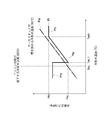
また、図4に示すように、ECU140は、第一所定温度TwL1を境界として冷却水温度に関する目標圧力の設定を変更する制御を備えず、目標圧力グラフPtの部位Ptbの目標圧力を、部位Ptaと同様にして冷却水温度に対応する冷媒の飽和蒸気圧に基づく目標圧力としてもよい。
また、ECU140は、冷却水の温度TwLに対応する冷媒の飽和蒸気圧PsLを目標圧力の下限値として備え、圧力センサ131によって検出される圧力が、飽和蒸気圧PsLを下回らないように、流量調整弁130を制御してもよい。このような制御をしても、冷媒は、冷却水温度に対応する冷媒の飽和蒸気圧よりも大きい圧力を有するため、冷却水ボイラ112での熱交換で冷却水から吸収する熱量を、蒸発潜熱を含まずに低く抑えることができる。
また、ECU140は、冷却水の温度TwLに対応する冷媒の飽和蒸気圧PsLを目標圧力の下限値として備え、圧力センサ131によって検出される圧力が、飽和蒸気圧PsLを下回らないように、流量調整弁130を制御してもよい。このような制御をしても、冷媒は、冷却水温度に対応する冷媒の飽和蒸気圧よりも大きい圧力を有するため、冷却水ボイラ112での熱交換で冷却水から吸収する熱量を、蒸発潜熱を含まずに低く抑えることができる。
また、図5に示すように、冷却水温度が第一所定温度TwL1(TwL1=TwL[60℃]+ΔTe)未満の場合、ECU140は、温度TwL(60℃)での冷媒の飽和蒸気圧PsLよりも大きい一定の圧力を目標圧力とし、圧力センサ131の検出圧力が目標圧力となるように、流量調整弁130を制御してもよい。このような制御をしても、冷媒は、冷却水ボイラ112での熱交換で冷却水から吸収する熱量を、蒸発潜熱を含まずに低く抑えることができる。
また、図4に示すように、ECU140は、第二所定温度TwH(90℃)を境界として冷却水温度に関する目標圧力の設定を変更する制御を備えず、目標圧力グラフPtの部位Ptcの目標圧力を、部位Ptaと同様にして冷却水温度に対応する冷媒の飽和蒸気圧に基づく目標圧力としてもよい。
また、実施の形態では、ECU140は、流量調整弁130を使用してバイパス流路3の流路断面積を調節することによって、圧力センサ131の検出圧力(冷却水ボイラ112に流入する冷媒の圧力)を調節していたが、これに限定されるものでない。
図6に示すように、ランキンサイクル201のポンプ111の駆動軸119がエンジン10と連結されない場合、実施の形態のオルタネータ118をモータ及び発電機の機能を有するモータジェネレータ218としてもよい。このとき、ECU140は、モータジェネレータ218が駆動する駆動軸119の回転数を制御することによって、ポンプ111及び膨張機114の回転数を調節し、圧力センサ131の検出圧力を調節してもよい。
また、図6において、ポンプ111とモータジェネレータ218との間の駆動軸119にクラッチを介在させる等して、ポンプ111と膨張機114とが個別に動作する場合は、ポンプ111を電動としてポンプ111への電力を制御することによってその回転数を調節する、又は、モータジェネレータ218の回転を制御して膨張機114の回転数を調節し、それにより圧力センサ131の検出圧力が調節されてもよい。
図6に示すように、ランキンサイクル201のポンプ111の駆動軸119がエンジン10と連結されない場合、実施の形態のオルタネータ118をモータ及び発電機の機能を有するモータジェネレータ218としてもよい。このとき、ECU140は、モータジェネレータ218が駆動する駆動軸119の回転数を制御することによって、ポンプ111及び膨張機114の回転数を調節し、圧力センサ131の検出圧力を調節してもよい。
また、図6において、ポンプ111とモータジェネレータ218との間の駆動軸119にクラッチを介在させる等して、ポンプ111と膨張機114とが個別に動作する場合は、ポンプ111を電動としてポンプ111への電力を制御することによってその回転数を調節する、又は、モータジェネレータ218の回転を制御して膨張機114の回転数を調節し、それにより圧力センサ131の検出圧力が調節されてもよい。
また、図7に示すランキンサイクル301のように、ポンプ111はエンジン10と連結されず、モータ322によって駆動されてもよい。ECU140は、モータ322の回転数を制御することによって、ポンプ111の回転数を調節し、圧力センサ131の検出圧力を調節できる。このとき、膨張機114は、その駆動軸114aと、エンジン10によって回転駆動されるプーリ119bとを電磁クラッチ119aを介して連結させ、さらに、オルタネータ118が駆動軸114aを共有している。
また、図8に示すランキンサイクル401のように、ポンプ111がオルタネータ118及び膨張機114と連結されずにプーリ119bとのみ連結され、膨張機114とオルタネータ118とが駆動軸114aによって連結されるようにしてもよい。このとき、ECU140は、オルタネータ118の負荷を変更することによって、膨張機114の回転数を調節し、圧力センサ131の検出圧力を調節できる。
また、膨張機114を、その吸入容積を任意に変更可能なものとしてもよい。吸入容積を変更することで、膨張機114が移送する冷媒の流量(体積流量)が変更され、それによって、膨張機114の上流側流路の冷媒圧力が変更されるため、圧力センサ131の検出圧力を調節できる。
また、膨張機114を、その吸入容積を任意に変更可能なものとしてもよい。吸入容積を変更することで、膨張機114が移送する冷媒の流量(体積流量)が変更され、それによって、膨張機114の上流側流路の冷媒圧力が変更されるため、圧力センサ131の検出圧力を調節できる。
また、実施の形態のランキンサイクル101において、バイパス流路3は、第一流路1の流路部1aを第二流路2の流路部2bに連通していたが、これに限定されるものでない。バイパス流路3は、第二流路2に対して、流路部2a、2c及び2dのいずれと接続されてもよい。
また、実施の形態のランキンサイクル101において、バイパス流路3は、複数あってもよい。
また、実施の形態のランキンサイクル101において、バイパス流路3は、複数あってもよい。
また、実施の形態のランキンサイクル101は、冷却水ボイラ112及び廃ガスボイラ113の2つの熱交換器を備えていたが、これに限定されるものでなく、3つ以上備えていてもよい。ランキンサイクル101は、エアコンディショナの冷媒とランキンサイクル101の冷媒との熱交換器を備えていてもよく、ハイブリッドカーにおいて使用されるモータの冷却水とランキンサイクル101の冷媒との熱交換器を備えていてもよい。このとき、これらの熱交換器及び冷却水ボイラ112のうちから選択した熱交換器の熱媒体の温度に対応する冷媒の飽和蒸気圧以下となる目標圧力を設定し、目標圧力に基づき第一流路1の冷媒の圧力を制御することによって、選択された熱交換器における冷媒の吸熱量を大きくすることができる。
3 バイパス流路(圧力調整手段)、10a エンジン駆動軸(動力伝達機構)、10b エンジンプーリ(動力伝達機構)、10c 駆動ベルト(動力伝達機構)、101,201,301,401 ランキンサイクル、111 ポンプ(流体圧送装置)、112 冷却水ボイラ(第一熱交換器)、113 廃ガスボイラ(第二熱交換器)、114 膨張機(流体膨張器)、115 コンデンサ(凝縮器)、119 駆動軸(動力伝達機構)、119a 電磁クラッチ(動力伝達機構)、119b プーリ(動力伝達機構)、130 流量調整弁(圧力調整手段)、131 圧力センサ(圧力検出器)、132 冷却水温度センサ(温度検出器)、140 ECU(制御装置)。
Claims (8)
- 作動流体の循環路に、作動流体と低温側熱媒体とを熱交換する第一熱交換器、作動流体と高温側熱媒体とを熱交換する第二熱交換器、作動流体を膨張させることによって駆動力を発生する流体膨張器、作動流体を凝縮させる凝縮器、及び、作動流体を前記第一熱交換器に移送する流体圧送装置が順次設けられたランキンサイクルにおいて、
前記流体膨張器の入口の作動流体の圧力を検出する圧力検出器と、
前記第一熱交換器に流入する低温側熱媒体の温度を検出する温度検出器と、
前記流体膨張器の入口の作動流体の圧力を調節する圧力調整手段と、
前記圧力調整手段を制御する制御装置とを備え、
前記制御装置は、前記温度検出器によって検出される低温側熱媒体の温度に対応する作動流体の飽和蒸気圧以下となる目標圧力を算出し、前記圧力検出器によって検出される圧力が前記目標圧力となるように、前記圧力調整手段を制御するランキンサイクル。 - 前記圧力調整手段は、前記第一熱交換器への作動流体の流入量を調節することによって、作動流体の圧力を調節する請求項1に記載のランキンサイクル。
- 前記圧力調整手段は、
前記流体圧送装置から前記第一熱交換器に向かう作動流体の流路を、前記流体膨張器から前記流体圧送装置に向かう作動流体の流路に連通するバイパスと、
前記バイパスにおける作動流体の流量を調節可能な流量調整弁とである請求項2に記載のランキンサイクル。 - 前記バイパスは、前記流体膨張器から前記流体圧送装置に向かう作動流体の流路における、前記凝縮器と前記流体圧送装置との間に接続する請求項3に記載のランキンサイクル。
- 前記制御装置は、前記温度検出器によって検出される低温側熱媒体の温度が第一所定温度未満の場合、前記圧力検出器によって検出される圧力が前記目標圧力よりも高くなるように、前記圧力調整手段を制御する請求項1~4のいずれか一項に記載のランキンサイクル。
- 前記制御装置は、前記温度検出器によって検出される低温側熱媒体の温度が第一所定温度未満の場合、前記圧力検出器によって検出される圧力が前記第一所定温度に対応する前記目標圧力以上となるように、前記圧力調整手段を制御する請求項1~4のいずれか一項に記載のランキンサイクル。
- 車両に搭載される請求項1~6のいずれか一項に記載のランキンサイクルにおいて、
前記流体圧送装置は、動力伝達機構を介して互いの駆動力を伝達可能に車両のエンジンに連結されるランキンサイクル。 - 前記流体圧送装置と前記流体膨張器とは、駆動軸を共有する請求項1~7のいずれか一項に記載のランキンサイクル。
Applications Claiming Priority (2)
| Application Number | Priority Date | Filing Date | Title |
|---|---|---|---|
| JP2011-146026 | 2011-06-30 | ||
| JP2011146026A JP2013011258A (ja) | 2011-06-30 | 2011-06-30 | ランキンサイクル |
Publications (1)
| Publication Number | Publication Date |
|---|---|
| WO2013002018A1 true WO2013002018A1 (ja) | 2013-01-03 |
Family
ID=47423917
Family Applications (1)
| Application Number | Title | Priority Date | Filing Date |
|---|---|---|---|
| PCT/JP2012/064992 Ceased WO2013002018A1 (ja) | 2011-06-30 | 2012-06-12 | ランキンサイクル |
Country Status (2)
| Country | Link |
|---|---|
| JP (1) | JP2013011258A (ja) |
| WO (1) | WO2013002018A1 (ja) |
Cited By (2)
| Publication number | Priority date | Publication date | Assignee | Title |
|---|---|---|---|---|
| JP2013044253A (ja) * | 2011-08-23 | 2013-03-04 | Mitsubishi Electric Corp | 排熱回生システム |
| FR3022496A1 (fr) * | 2014-06-19 | 2015-12-25 | Renault Sas | Systeme de propulsion pour vehicule automobile hybride comprenant des moyens de recuperation de l'energie thermique perdue |
Families Citing this family (2)
| Publication number | Priority date | Publication date | Assignee | Title |
|---|---|---|---|---|
| JP6610145B2 (ja) * | 2015-10-07 | 2019-11-27 | いすゞ自動車株式会社 | 発電装置及び発電装置の制御方法 |
| JP2019019797A (ja) * | 2017-07-20 | 2019-02-07 | パナソニック株式会社 | 熱電併給システム及び熱電併給システムの運転方法 |
Citations (10)
| Publication number | Priority date | Publication date | Assignee | Title |
|---|---|---|---|---|
| JP2006177266A (ja) * | 2004-12-22 | 2006-07-06 | Denso Corp | 熱機関の廃熱利用装置 |
| JP2007218456A (ja) * | 2006-02-14 | 2007-08-30 | Denso Corp | 車両用廃熱利用装置およびその制御方法 |
| JP2007322023A (ja) * | 2006-05-30 | 2007-12-13 | Denso Corp | 廃熱利用装置を備える冷凍装置 |
| JP2008267341A (ja) * | 2007-04-24 | 2008-11-06 | Toshiba Corp | 廃熱回収装置 |
| JP2009068459A (ja) * | 2007-09-14 | 2009-04-02 | Denso Corp | 廃熱利用装置 |
| JP2009097391A (ja) * | 2007-10-15 | 2009-05-07 | Toyota Motor Corp | 廃熱回収装置及びこれを備えたエンジン |
| WO2009101977A1 (ja) * | 2008-02-14 | 2009-08-20 | Sanden Corporation | 内燃機関の廃熱利用装置 |
| JP2010048129A (ja) * | 2008-08-20 | 2010-03-04 | Sanden Corp | 内燃機関の廃熱利用装置 |
| JP2010174848A (ja) * | 2009-02-02 | 2010-08-12 | Mitsubishi Electric Corp | 排熱回生システム |
| JP2011058502A (ja) * | 2004-12-07 | 2011-03-24 | Denso Corp | 熱発電装置、電源制御装置、及びその電力管理方法 |
-
2011
- 2011-06-30 JP JP2011146026A patent/JP2013011258A/ja active Pending
-
2012
- 2012-06-12 WO PCT/JP2012/064992 patent/WO2013002018A1/ja not_active Ceased
Patent Citations (10)
| Publication number | Priority date | Publication date | Assignee | Title |
|---|---|---|---|---|
| JP2011058502A (ja) * | 2004-12-07 | 2011-03-24 | Denso Corp | 熱発電装置、電源制御装置、及びその電力管理方法 |
| JP2006177266A (ja) * | 2004-12-22 | 2006-07-06 | Denso Corp | 熱機関の廃熱利用装置 |
| JP2007218456A (ja) * | 2006-02-14 | 2007-08-30 | Denso Corp | 車両用廃熱利用装置およびその制御方法 |
| JP2007322023A (ja) * | 2006-05-30 | 2007-12-13 | Denso Corp | 廃熱利用装置を備える冷凍装置 |
| JP2008267341A (ja) * | 2007-04-24 | 2008-11-06 | Toshiba Corp | 廃熱回収装置 |
| JP2009068459A (ja) * | 2007-09-14 | 2009-04-02 | Denso Corp | 廃熱利用装置 |
| JP2009097391A (ja) * | 2007-10-15 | 2009-05-07 | Toyota Motor Corp | 廃熱回収装置及びこれを備えたエンジン |
| WO2009101977A1 (ja) * | 2008-02-14 | 2009-08-20 | Sanden Corporation | 内燃機関の廃熱利用装置 |
| JP2010048129A (ja) * | 2008-08-20 | 2010-03-04 | Sanden Corp | 内燃機関の廃熱利用装置 |
| JP2010174848A (ja) * | 2009-02-02 | 2010-08-12 | Mitsubishi Electric Corp | 排熱回生システム |
Cited By (2)
| Publication number | Priority date | Publication date | Assignee | Title |
|---|---|---|---|---|
| JP2013044253A (ja) * | 2011-08-23 | 2013-03-04 | Mitsubishi Electric Corp | 排熱回生システム |
| FR3022496A1 (fr) * | 2014-06-19 | 2015-12-25 | Renault Sas | Systeme de propulsion pour vehicule automobile hybride comprenant des moyens de recuperation de l'energie thermique perdue |
Also Published As
| Publication number | Publication date |
|---|---|
| JP2013011258A (ja) | 2013-01-17 |
Similar Documents
| Publication | Publication Date | Title |
|---|---|---|
| JP5621721B2 (ja) | ランキンサイクル | |
| CN103154488B (zh) | 内燃机的废热利用装置 | |
| CN103748347B (zh) | 朗肯循环 | |
| US20110088397A1 (en) | Waste heat recovery system | |
| JP5338730B2 (ja) | 廃熱回生システム | |
| US20120073294A1 (en) | Rankine cycle system | |
| JP5333659B2 (ja) | 廃熱回生システム | |
| EP2345796A2 (en) | Waste heat recovery system | |
| KR101708109B1 (ko) | 폐열 회수 장치 및 폐열 회수 방법 | |
| JP5008441B2 (ja) | 内燃機関の廃熱利用装置 | |
| WO2009133620A1 (ja) | 内燃機関の廃熱利用装置 | |
| JP6344020B2 (ja) | 車両 | |
| JP2016056686A (ja) | 圧縮装置 | |
| JP2014231738A (ja) | 廃熱回生システム | |
| WO2012039225A1 (ja) | ランキンサイクル装置 | |
| JP5894756B2 (ja) | ランキンサイクルシステム | |
| JP2013011258A (ja) | ランキンサイクル | |
| JP6433749B2 (ja) | 熱エネルギー回収装置 | |
| JP4140543B2 (ja) | 廃熱利用装置 | |
| JP5571978B2 (ja) | ヒートポンプシステム | |
| JP4588644B2 (ja) | 廃熱利用装置を備える冷凍装置 | |
| JP2008184906A (ja) | 内燃機関の廃熱利用装置 | |
| CN109113819B (zh) | 热能回收系统及搭载该热能回收系统的船舶 | |
| JP5842668B2 (ja) | ランキンサイクル | |
| JP2013044239A (ja) | 車両用排熱回収装置 |
Legal Events
| Date | Code | Title | Description |
|---|---|---|---|
| 121 | Ep: the epo has been informed by wipo that ep was designated in this application |
Ref document number: 12804012 Country of ref document: EP Kind code of ref document: A1 |
|
| NENP | Non-entry into the national phase |
Ref country code: DE |
|
| 122 | Ep: pct application non-entry in european phase |
Ref document number: 12804012 Country of ref document: EP Kind code of ref document: A1 |