WO2012176797A1 - 通信システム - Google Patents
通信システム Download PDFInfo
- Publication number
- WO2012176797A1 WO2012176797A1 PCT/JP2012/065724 JP2012065724W WO2012176797A1 WO 2012176797 A1 WO2012176797 A1 WO 2012176797A1 JP 2012065724 W JP2012065724 W JP 2012065724W WO 2012176797 A1 WO2012176797 A1 WO 2012176797A1
- Authority
- WO
- WIPO (PCT)
- Prior art keywords
- server
- polling
- communication
- terminal
- home device
- Prior art date
Links
Images
Classifications
-
- H—ELECTRICITY
- H04—ELECTRIC COMMUNICATION TECHNIQUE
- H04L—TRANSMISSION OF DIGITAL INFORMATION, e.g. TELEGRAPHIC COMMUNICATION
- H04L61/00—Network arrangements, protocols or services for addressing or naming
- H04L61/09—Mapping addresses
- H04L61/25—Mapping addresses of the same type
- H04L61/2503—Translation of Internet protocol [IP] addresses
- H04L61/255—Maintenance or indexing of mapping tables
- H04L61/2553—Binding renewal aspects, e.g. using keep-alive messages
-
- H—ELECTRICITY
- H04—ELECTRIC COMMUNICATION TECHNIQUE
- H04L—TRANSMISSION OF DIGITAL INFORMATION, e.g. TELEGRAPHIC COMMUNICATION
- H04L67/00—Network arrangements or protocols for supporting network services or applications
- H04L67/01—Protocols
-
- H—ELECTRICITY
- H04—ELECTRIC COMMUNICATION TECHNIQUE
- H04L—TRANSMISSION OF DIGITAL INFORMATION, e.g. TELEGRAPHIC COMMUNICATION
- H04L63/00—Network architectures or network communication protocols for network security
- H04L63/02—Network architectures or network communication protocols for network security for separating internal from external traffic, e.g. firewalls
- H04L63/0281—Proxies
-
- H—ELECTRICITY
- H04—ELECTRIC COMMUNICATION TECHNIQUE
- H04L—TRANSMISSION OF DIGITAL INFORMATION, e.g. TELEGRAPHIC COMMUNICATION
- H04L61/00—Network arrangements, protocols or services for addressing or naming
- H04L61/09—Mapping addresses
- H04L61/25—Mapping addresses of the same type
- H04L61/2503—Translation of Internet protocol [IP] addresses
- H04L61/2514—Translation of Internet protocol [IP] addresses between local and global IP addresses
-
- H—ELECTRICITY
- H04—ELECTRIC COMMUNICATION TECHNIQUE
- H04L—TRANSMISSION OF DIGITAL INFORMATION, e.g. TELEGRAPHIC COMMUNICATION
- H04L61/00—Network arrangements, protocols or services for addressing or naming
- H04L61/09—Mapping addresses
- H04L61/25—Mapping addresses of the same type
- H04L61/2503—Translation of Internet protocol [IP] addresses
- H04L61/256—NAT traversal
-
- H—ELECTRICITY
- H04—ELECTRIC COMMUNICATION TECHNIQUE
- H04L—TRANSMISSION OF DIGITAL INFORMATION, e.g. TELEGRAPHIC COMMUNICATION
- H04L61/00—Network arrangements, protocols or services for addressing or naming
- H04L61/50—Address allocation
- H04L61/5007—Internet protocol [IP] addresses
- H04L61/5014—Internet protocol [IP] addresses using dynamic host configuration protocol [DHCP] or bootstrap protocol [BOOTP]
-
- H—ELECTRICITY
- H04—ELECTRIC COMMUNICATION TECHNIQUE
- H04L—TRANSMISSION OF DIGITAL INFORMATION, e.g. TELEGRAPHIC COMMUNICATION
- H04L67/00—Network arrangements or protocols for supporting network services or applications
- H04L67/50—Network services
- H04L67/60—Scheduling or organising the servicing of application requests, e.g. requests for application data transmissions using the analysis and optimisation of the required network resources
- H04L67/61—Scheduling or organising the servicing of application requests, e.g. requests for application data transmissions using the analysis and optimisation of the required network resources taking into account QoS or priority requirements
Definitions
- the present invention relates to a communication system that performs communication between a server and a terminal.
- a polling communication system provided with a polling server is known as a means for grasping the state of a terminal by a server in the following Patent Document 1 or the like.
- This polling communication system is a server system that is connected to a plurality of home devices and communicates with the plurality of home devices. Normally, home devices perform polling communication by being distributed to a plurality of polling servers. When an event for exchanging information with each home device occurs, the center server transmits a communication request of the home device to a plurality of polling servers. When the inquiry packet is transmitted to the polling server by the home device, the polling server returns a response packet indicating that there is a center server communication request. Thus, the home device makes a packet request to the center server, and the packet is transmitted from the center server to the home device.
- an object of the present invention is to provide a communication system capable of suppressing the amount of polling communication even when a terminal requests a plurality of services.
- a communication system includes a plurality of servers provided in the first network, a terminal provided in the second network, the first network, and the second network. And a relay device that relays packets communicated between the first network and the second network, and after receiving a communication request for the terminal from the server provided in the first network
- a polling server that returns a response signal indicating that there is a communication request from the server to the terminal when receiving a query signal from the terminal, the terminal responding that there is a communication request from the server Is received from the polling server, communication is started to the server that has transmitted the communication request.
- the polling server includes storage means for storing priority information indicating a priority with which the server communicates with the terminal, When the polling server receives an interrogation signal from the terminal, the polling server returns the response signal including the communication request from the server and the priority information to the terminal, and the terminal is included in the response signal.
- the communication start order for the server that made the communication request is determined based on the priority information.
- the server includes, in a communication request transmitted to the polling server, attribute information requested from a terminal serving as a communication partner, When a query signal is received from the terminal, the response signal is returned to the terminal including the communication request from the server and the attribute information, and the terminal returns the attribute information included in the response signal. Terminal information based on the request is transmitted to the server that has made the communication request.
- the polling server stores unique attribute information set in advance in the server, and the unique attribute information is included in the response signal. It is characterized by including.
- the fifth aspect includes confidentiality determination information indicating whether or not the polling server conceals information to be included in the response signal
- the polling server when a plurality of servers are connected to the polling server and the polling server receives a communication request from the server, the polling server sends a response signal indicating that there is a communication request from the server to the terminal. To start communication with the server from the terminal. According to such a communication system, the amount of polling communication can be suppressed even when the terminal requests a plurality of services.
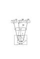
- FIG. 1 is a block diagram showing a configuration of a polling communication system shown as an embodiment of the present invention.
- FIG. 2 is a block diagram showing a state in which communication requests are generated from a plurality of service servers in the polling communication system shown as an embodiment of the present invention.
- FIG. 3 is a block diagram illustrating a state in which communication is started from a home device in order of priority with respect to a plurality of service servers in the polling communication system shown as an embodiment of the present invention.
- FIG. 4 is a sequence diagram showing signals exchanged between the units in the polling communication system shown as an embodiment of the present invention.
- FIG. 5 is a block diagram showing a polling communication system as a comparative example.
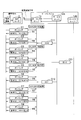
- FIG. 6 is a sequence diagram showing how the service server property information is stored in the polling server in the polling communication system shown as an embodiment of the present invention.
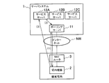
- the polling communication system to which the present invention is applied is configured, for example, as shown in FIG.
- This polling communication system includes a server system 1, an in-home device 2 in a customer premises, and a NAT (Network Address Translation) router 3 as a relay device.
- a server system 1 an in-home device 2 in a customer premises
- a NAT (Network Address Translation) router 3 as a relay device.
- the server system 1 is provided in a first network such as an IP network NW.
- the home device 2 is provided in a second network such as a customer home network different from the first network.
- the NAT router 3 is provided between the first network and the second network.
- the NAT router 3 since the NAT router 3 exists, the first network cannot communicate with the second network built in the customer premises. That is, with the global address transmitted from the first network, the packet does not reach the home device 2 to which the private address is assigned in the customer home. Therefore, in this polling communication system, it is necessary to start communication from the home device 2 to the service server 12. Therefore, polling communication is performed between the home device 2 and the polling server 11 in order for the home device 2 to recognize that the service server 12 has requested communication with the home device 2.
- the server system 1 includes a plurality of service servers 12A, 12B, and 12C (hereinafter simply referred to as “service server 12” when collectively referred to).
- the server system 1 also includes a polling server 11 that can communicate with a plurality of service servers 12.
- FIG. 1 shows an example in which three service servers 12A, 12B, and 12C are connected to a single polling server 11, the present invention is not limited to this.
- the service servers 12A, 12B, and 12C have different attributes (functions). That is, the service servers 12A, 12B, and 12C operate with different software, and exchange different information with the in-home device 2.
- the service server 12A has, for example, a service function for managing the security in the customer premises.
- the service server 12A acquires security information such as electric locks and security sensors related to security in the customer premises, and provides the security information to the portable terminal held by the user when an abnormality occurs.
- the service server 12B has, for example, a service function for remotely operating each device in the customer's home in response to a request from a mobile terminal or home device 2 held by the user.
- the service server 12B transmits a control signal to the home appliance 2 when a control signal for controlling an air conditioner or the like provided in the customer's home is supplied from a portable terminal held by the user.
- the service server 12C has, for example, a service function for managing the power of devices in the customer's home.
- the service server 12C acquires information such as the amount of power per unit time (such as one day or one hour) provided in the customer premises or instantaneous power, the service server 12C controls the premises equipment 2 to transmit the information.
- the polling server 11 can communicate with a plurality of service servers 12 included in the server system 1 in the first network.
- the polling server 11 performs polling communication with the home device 2 in the second network via the first network including the IP network NW.
- the polling server 11 receives a communication request for requesting communication with the home device 2 from the service server 12.
- the polling server 11 returns a response signal including the communication request to the home device 2 in response to receiving the inquiry signal in the polling communication from the home device 2.
- the home device 2 performs polling communication in which a question signal is transmitted to the polling server 11 every predetermined period and a response signal to the question signal is received.
- the in-home device 2 transmits a question signal to the polling server 11 connected to the plurality of service servers 12 in order to enjoy services provided by the plurality of service servers 12.
- the response signal includes a communication request
- the in-home device 2 performs direct communication with the service server 12 that has transmitted the communication request to the polling server 11.
- the in-home device 2 transmits a question signal to the polling server 11 via the NAT router 3 when a predetermined polling communication interval is reached.
- the polling server 11 determines whether or not a communication request is received from the service server 12 in response to receiving the question signal. When the communication request is not received from the service server 12, the polling server 11 returns a response signal including that there is no communication request to the home device 2.
- the service server 12A requesting connection with the home device 2 transmits a communication request to the polling server 11.
- the polling server 11 stores the received communication request.
- the home device 2 transmits a question signal to the polling server 11 according to the procedure (1).
- the polling server 11 receives the interrogation signal
- the polling server 11 receives the communication request from the service server 12A, and returns a response signal including the communication request to the home device 2.
- the home device 2 When the home device 2 receives a response signal including a communication request from the polling server 11, the home device 2 extracts the communication request included in the response signal. The in-home device 2 recognizes that the service server 12A requests communication by the communication request.
- step (3) the home device 2 transmits a packet request to the service server 12A in response to the communication request, and starts communication with the service server 12A that has transmitted the communication request.
- the service server 12 ⁇ / b> A can transmit a response packet to the home device 2 in response to receiving the packet request from the home device 2.
- the home device 2 acquires information such as the state of the electric lock in the home and the detection result of the security sensor or the camera. Thereby, the in-home device 2 can transmit the security information requested by the service server 12A.
- this polling communication system even when the home device 2 needs to communicate with a plurality of service servers 12, the polling communication is concentrated in the polling server 11. Thereby, the home device 2 does not need to perform polling communication for each service. Further, according to this polling communication system, communication requests can be aggregated with respect to the polling server 11 even when a plurality of service servers 12 request communication with the home appliance 2.
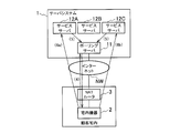
- communication requests may be transmitted from the plurality of service servers 12 to the server system 1 within a predetermined polling communication interval in which the home device 2 performs polling communication. Yes (procedure (5)).
- the home device 2 can recognize that it is necessary to start communication between the service server 12A and the service server 12C by the procedure (4).
- the in-home device 2 transmits a packet request to the service servers 12A and the server system 12C substantially simultaneously (procedures (6a) and (6b)).
- 6a) and (6b) substantially simultaneously
- the polling communication of the in-home device 2 and the service server 12 can be aggregated in the polling server 11, and compared with the case where the polling communication is performed from each in-home device 2 to each service server 12, respectively.
- the amount of communication can be reduced.
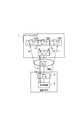
- the in-home device 2 may operate based on the priority information of the service server 12.
- the polling server 11 includes storage means for storing priority information indicating the priority with which the service server 12 communicates with the home device 2.
- This priority information is set by the attribute of the service server 12, for example.
- the priority of the service server 12 that handles security information with a high degree of urgency is “high”.
- the service server 12 that handles power information with low urgency is set to “low”.
- the priority information may be arbitrarily determined by a user who operates the home device 2.
- the polling server 11 When the polling server 11 receives the inquiry signal from the home device 2, the polling server 11 returns the response signal including the communication request and priority information from the service server 12 to the home device 2 (procedure (4)). At this time, the polling server 11 adds the priority information of the service server 12 together with the communication request of the service server 12 that has transmitted the communication request.
- the home device 2 determines the communication start order for the service server 12 that has requested communication based on the priority information included in the response signal.
- the home device 2 first transmits a packet request to the service server 12A (procedure (6)), and then to the server system 12C.
- the packet request is transmitted (procedure (7)).
- the home device 2 even when communication requests are generated from a plurality of service servers 12 within a predetermined polling communication interval performed by the home device 2, the home device 2 depends on the priority. Can start communication with a plurality of service servers 12. Therefore, it is possible to demonstrate an effect that a connection can be quickly secured from the home device 2 with the service server 12 having a high degree of urgency.
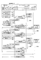
- the server system 1 includes two servers, a service server 12A and a service server 12B.
- the home device 2 transmits the inquiry signals C1 and C2 at every predetermined polling communication interval. Since there is no communication request from the service servers 12A and 12B to the polling server 11 within the period when the inquiry signals C1 and C2 are transmitted, the polling server 11 sends response signals R1 and R2 indicating that there is no communication request to the in-home equipment 2 Send to.
- the service server 12A transmits a communication request C11 to the polling server 11. Thereby, the polling server 11 stores the communication request of the service server 12A.
- the polling server 11 transmits a response signal R3 in response to the question signal C3 to the home device 2.
- the polling server 11 since the polling server 11 has received the communication request from the service server 12A first, the communication request transmitted from the service server 12A is included in the response signal R3.
- the home device 2 When the home device 2 receives the response signal R3 from the polling server 11, the home device 2 acquires a communication request from the response signal R3. Based on this communication request, the in-home device 2 recognizes that the service server 12A is requesting communication with itself. Thereby, the in-home device 2 transmits a packet request C12 for acquiring communication contents from the service server 12A to the service server 12A.
- the service server 12A acquires the packet request C12 from the home device 2.
- the service server 12A transmits data R12 toward the home device 2 in response to the packet request C12.
- Examples of the data directed to the home appliance 2 include a command for acquiring sensor values of various sensors provided in the customer's home, and a command for controlling an air conditioner, a lighting device, and a security device.
- the home device 2 acquires the data R12 directed to the home device 2 transmitted from the service server 12A via the NAT router 3.
- the in-home device 2 operates according to the data R12 in response to the acquisition of the data R12 directed to the in-home device 2, and acquires various sensor values, controls various devices, and the like.
- the polling server 11 transmits a response signal R4 to the in-home device 2 in response to the inquiry signal C4 from the in-home device 2.
- the response signal R4 includes that the service server 12B requests connection.
- the in-home device 2 can transmit the packet request C13 to the service server 12B, and can acquire the data R13 directed to the in-home device 2 from the service server 12B.
- the polling communication system even if the service server 12 cannot connect directly to the home device 2, the polling communication is performed from the home device 2, so that The service server 12 can be connected.
- communication requests C14 and C22 are transmitted from the two service servers 12A and 12B in the polling communication interval after the inquiry signal C5 and the response signal R5 are transmitted and received. is there.
- the polling server 11 stores two communication requests of the service server 12A and the service server 12B.
- the polling server 11 sends a response signal R6 including a request for communication transmitted from the service server 12A and the service server 12B to the home device 2. Send to.
- the polling server 11 may include the priority information of the service server 12 stored in advance in the response signal R6.
- the home device 2 can transmit packet requests C15 and C17 almost simultaneously, and can receive data R15 and R17 directed to the home device 2 from the service server 12A and the service server 12B.
- the in-home device 2 When the priority information is included in the response signal R6 and the service server 12A has a higher priority than the service server 12B, the in-home device 2 first transmits a packet request C15 to the service server 12A. The data R15 for the home device 2 is acquired. Thereafter, the in-home device 2 transmits a packet request C16 to the service server 12B and acquires data R16 directed to the in-home device 2.
- the amount of polling communication can be suppressed even when the home device 2 uses a plurality of services.
- the home device 2 must transmit a question signal to the three service servers 12 to obtain a response signal. Don't be.
- security information has a high degree of urgency, and polling communication needs to be performed with high frequency.
- polling communication system of the present application even if there are a plurality of service servers 12, polling communication may be performed with respect to a single polling server 11, and the communication amount can be suppressed.
- property information may be included in a communication request transmitted from the service server 12 to the polling server 11.
- This property information is information indicating the attributes of the service server 12.
- the property information includes information that the service server 12 requests from the home device 2 and contents that the service server 12 wants to control the home device 2.
- the polling server 11 When the polling server 11 receives the property information from the service server 12, the polling server 11 includes the communication request and the property information in the response signal that has received the inquiry signal from the home device 2 thereafter. Upon receiving the response signal, the home device 2 can acquire the property information included in the response signal. On the other hand, the home device 2 acquires the information (terminal information) of the home device 2 based on the property information and includes it in the packet request transmitted to the service server 12.
- the service server 12 can retrieve information on the home device 2 included in the packet request and acquire information based on the property information transmitted to the polling server 11 itself.
- the property information of the service server 12A is included in the communication request C11 in FIG.
- the polling server 11 stores the property information transmitted from the service server 12A together with the communication request. Thereafter, in response to the inquiry signal C3 being transmitted from the home device 2, the polling server 11 includes the property information in the response signal R3 and transmits the response signal R3 to the home device 2.
- the in-home device 2 refers to the property information and can directly return to the service server 12A by including information (terminal information) based on the property information in the packet request.
- the necessary property information can be included in the response signal transmitted from the polling server 11 to the in-home device 2, and the number of times of communication from the terminal to the service server 12 in response to the communication request is determined. Can be reduced. Therefore, according to this polling communication system, together with the above-described embodiment, it is possible to further suppress the compression of the communication band.
- the polling server 11 stores property information (unique attribute information) preset in the service server 12 and includes the property information in the response signal. Also good.
- This property information is default (initialization) property information designated by the service server 12A and the service server 12B.
- This default property information is information unique to the service server 12A and the service server 12B. This information includes, for example, numerically specified security information, power / energy information, and the like.
- the default property information of the service server 12A is “5”, and the default property information of the service server 12B is “7”.
- the home device 2 transmits a question signal C ⁇ b> 1 to the polling server 11. Even if there is no communication request, the polling server 11 stores the default property information of the service server 12A and the service server 12B in the response signal R1 to the question signal C1. Thereby, the in-home device 2 can acquire the default property information of the service server 12A and the service server 12B connected to the polling server 11. Thereafter, the same applies when the inquiry signal C2 and the response signal R2 are transmitted and received.
- the service server 12A transmits a communication request C11 including property information having a value “8” to the polling server 11 so as to transmit the changed information. To do.
- the polling server 11 Upon receiving the communication request C11 including the changed property information, the polling server 11 changes the property information of the service server 12A to “8” and stores it. Thereafter, a question signal C3 is transmitted from the home device 2, and the polling server 11 receives the question signal C3. The polling server 11 does not have a communication request and transmits a response signal R3 including the property information “8” changed by the service server 12A.
- the service server 12B transmits a communication request C21 including property information having a value “9” to the polling server 11 so as to transmit the changed information. To do.
- the polling server 11 When receiving the communication request C21 including the changed property information, the polling server 11 changes the property information of the service server 12B to “9” and stores it. Thereafter, a question signal C4 is transmitted from the home device 2, and the polling server 11 receives the question signal C4. The polling server 11 does not have a communication request and transmits a response signal R4 including the property information “9” changed by the service server 12B.
- the polling server 11 When the household device 2 transmits the inquiry signal C5 at the subsequent polling communication interval, the polling server 11 has no communication request, the property information of the service server 12A is “8”, and the property information of the service server 12B is “9”. "A response signal R5" is transmitted.
- the service server 12A transmits its property information “1” to the communication request C12. Thereby, the polling server 11 can further change the property information of the service server 12A.
- the service server 12 itself stores its own default property information in the polling server 11. Further, the service server 12 can store the changed property information in the polling server 11. Thus, when the polling server 11 receives the inquiry signal from the home device 2, the default property information of the service server 12 or the changed property information can be stored and transmitted in the response signal. Accordingly, the in-home device 2 can transmit terminal information based on the property information of the service server 12 to the service server 12.
- the polling server 11 responds to the inquiry signals C8 and C9 with the response signal R8, including the stored property information. R10 can be returned.
- the polling communication system can be connected to the service server 12 from the in-home device 2 based on the property information stored in the polling server 11 when there is a communication request from the service server 12. Therefore, according to this polling communication system, it is possible to suppress the communication amount between the in-home device 2 and the service server 12 and further suppress the tightness of the communication band.
- the polling server 11 has confidential determination information indicating whether or not information included in the response signal transmitted to the in-home device 2 is confidential.
- the polling server 11 returns a response signal including information to be included in the response signal to the home device 2 when the information to be included in the response signal does not need to be concealed due to the confidentiality determination information.
- the polling server 11 conceals the property information transmitted from the service server 12 together with the communication request or the property information stored in the polling server 11 as described above. For this reason, the polling server 11 compares the confidential determination information stored in advance with the property information.
- the confidentiality determination information is, for example, property information indicating the content of information communicated by the service server 12 connected to the polling server 11 and table data indicating whether the property information is confidential.
- the polling server 11 receives property information from the service server 12, the polling server 11 determines whether to hide the property information.
- the polling server 11 determines that the property information should be kept secret, the polling server 11 includes information indicating that the information exchanged with the service server 12 is kept secret in the response signal.
- the home device 2 When the home device 2 receives the response signal from the polling server 11, it can recognize that the information to conceal the information is included.
- the in-home device 2 transmits a packet request to the service server 12 using an encryption method and an encryption key set in advance with the service server 12. Thereby, the polling communication system can conceal what information is exchanged between the home device 2 and the service server 12.
- this polling communication system also conceals information transmitted from the service server 12 to the home device 2.
- the service server 12 transmits data destined for the home device 2 to the service server 12 using the encryption method and the encryption key set with the home device 2.
- the polling communication system can conceal what information is requested to the in-home device 2 by the service server 12.
- this polling communication system also conceals information transmitted from the home device 2 to the service server 12 as a result requested by the service server 12.
- the polling communication system can conceal the security information when the security information is transmitted from the home device 2 to the service server 12, for example.
- this polling communication system information exchanged between the polling server 11 and the home device 2 or between the home device 2 and the service server 12 can be concealed. Thereby, according to this polling communication system, even when a plurality of service servers 12 are connected to the polling server 11 and the in-home device 2 is connected to a single polling server 11, the information that the in-home device 2 communicates with Leakage can be suppressed.
Abstract
複数のサーバ12と、宅内機器2と、NATルータ3と、サーバ12から宅内機器2に対する通信要求を受信した後に宅内機器2から質問信号を受信した場合に、サーバ12からの通信要求があることの応答信号を宅内機器2に返信するポーリングサーバ11とを備え、宅内機器2は、サーバ12からの通信要求があることの応答信号をポーリングサーバ11から受信した場合に、当該通信要求を送信したサーバ12に対して通信を開始する。端末が複数のサービスを要求する場合あってもポーリング通信の通信量を抑制することができる。
Description
本発明は、サーバと端末との間で通信を行う通信システムに関する。
従来より、サーバによって端末の状態を把握するための手段として、ポーリングサーバを備えたポーリング通信システムが下記の特許文献1等で知られている。
このポーリング通信システムは、複数の宅内機器と接続されて、当該複数の宅内機器と通信するサーバシステムである。通常、宅内機器は、複数のポーリングサーバに分散して、ポーリング通信を行う。センターサーバは、各宅内機器と情報の授受を行うイベントが発生した場合に、当該宅内機器の通信要求を複数のポーリングサーバに送信する。宅内機器によってポーリングサーバに質問パケットが送信されると、ポーリングサーバはセンターサーバ通信要求があったことを表す応答パケットを返信する。これによって、宅内機器がセンターサーバにパケット要求をし、センターサーバから宅内機器にパケットが送信される。
しかしながら、従来のポーリング通信システムは、端末が複数のサービスサーバと接続する場合に、複数のサービスごとのポーリング通信をしていると、端末が要求するサービスが多くなるほどポーリング通信に要する通信量が多くなってしまう。
そこで、本発明は、上述した実情に鑑みて提案されたものであり、端末が複数のサービスを要求する場合あってもポーリング通信の通信量を抑制することができる通信システムを提供することを目的とする。
上記の課題を解決する第1の態様に係る通信システムは、前記第1ネットワークに設けられた複数のサーバと、前記第2ネットワークに設けられた端末と、前記第1ネットワークと前記第2ネットワークとの間に設けられ、前記第1ネットワークと前記第2ネットワークとの間で通信されるパケットを中継する中継装置と、前記第1ネットワークに設けられ前記サーバから前記端末に対する通信要求を受信した後に前記端末から質問信号を受信した場合に、前記サーバからの通信要求があることの応答信号を前記端末に返信するポーリングサーバとを備え、前記端末は、前記サーバからの通信要求があることの応答信号を前記ポーリングサーバから受信した場合に、当該通信要求を送信したサーバに対して通信を開始することを特徴とする。
第1の態様に係る通信システムであって、第2の態様は、前記ポーリングサーバは、前記サーバが前記端末との間で通信を行う優先度を示す優先度情報を記憶する記憶手段を備え、前記ポーリングサーバは、前記端末から質問信号を受信した場合に、前記応答信号に、前記サーバからの通信要求及び前記優先度情報を含めて前記端末に返信し、前記端末は、前記応答信号に含まれている優先度情報に基づいて前記通信要求をしたサーバに対する通信開始順序を決定することを特徴とする。
第1の態様に係る通信システムであって、第3の態様は、前記サーバは、前記ポーリングサーバに送信する通信要求に、通信相手となる端末に要求する属性情報を含め、前記ポーリングサーバは、前記端末から質問信号を受信した場合に、前記応答信号に、前記サーバからの通信要求及び前記属性情報を含めて前記端末に返信し、前記端末は、前記応答信号に含まれている属性情報に基づく端末情報を、前記通信要求をしたサーバに対して送信することを特徴とする。
第1の態様に係る通信システムであって、第4の態様は、前記ポーリングサーバは、前記サーバに予め設定された固有の属性情報を記憶しておき、前記応答信号に、前記固有の属性情報を含めることを特徴とする。
第3又は第4の何れかの態様に係る通信システムであって、第5の態様は、前記ポーリングサーバは、前記応答信号に含める情報を秘匿するか否かを示す秘匿判断情報を有し、前記応答信号に含める情報が前記秘匿判断情報によって秘匿が不要である場合に、当該応答信号に含める情報を含む応答信号を前記端末に返信することを特徴とする。
上述した態様の通信システムによれば、複数のサーバをポーリングサーバに接続し、ポーリングサーバがサーバから通信要求を受信した場合に、ポーリングサーバによって、サーバからの通信要求があることの応答信号を端末に返信し、端末からサーバに対して通信を開始する。このような通信システムによれば、端末が複数のサービスを要求する場合あってもポーリング通信の通信量を抑制することができる。
以下、本発明の実施の形態について図面を参照して説明する。
本発明を適用したポーリング通信システムは、例えば図1に示すように構成される。このポーリング通信システムは、サーバシステム1、顧客宅内の宅内機器2、及び、中継装置としてのNAT(Network Address Translation)ルータ3を備える。
このポーリング通信システムにおいて、サーバシステム1はIPネットワークNWといった第1ネットワークに設けられている。一方、宅内機器2は、第1ネットワークとは異なる顧客宅内ネットワークといった第2ネットワークに備えられる。NATルータ3は、第1ネットワークと第2ネットワークとの間に設けられている。
このポーリング通信システムにおいて、NATルータ3が存在するために、顧客宅内に構築された第2ネットワークへは、第1ネットワークからは通信できない。すなわち、第1ネットワークから送信されたグローバルアドレスでは、顧客宅内においてプライベートアドレスが付与されている宅内機器2にはパケットは届かない。したがって、このポーリング通信システムにおいては、宅内機器2からサービスサーバ12に対して通信を開始する必要がある。このため、サービスサーバ12が宅内機器2に対する通信を要求したことを宅内機器2が認識するために、宅内機器2とポーリングサーバ11との間でポーリング通信を行う。
このポーリング通信システムにおいて、サーバシステム1には、複数のサービスサーバ12A,12B,12C(以下、総称する場合には単に「サービスサーバ12」と呼ぶ。)が含まれる。また、サーバシステム1は、複数のサービスサーバ12と通信可能なポーリングサーバ11を備えている。なお、図1では、単一のポーリングサーバ11に対して3つのサービスサーバ12A,12B,12Cが接続されている例を示しているが、これに限るものではない。
サービスサーバ12A,12B,12Cは、それぞれ、異なる属性(機能)を備えている。すなわち、サービスサーバ12A,12B,12Cは、それぞれ異なるソフトウェアによって動作し、宅内機器2との間で異なる情報を授受する。
サービスサーバ12Aは、例えば、顧客宅内のセキュリティを管理するサービス機能を備えている。サービスサーバ12Aは、顧客宅内におけるセキュリティに関する電気錠、防犯センサ等のセキュリティ情報を取得し、異常が発生した時にユーザに保持される携帯端末にセキュリティ情報を提供する。
サービスサーバ12Bは、例えば、ユーザに保持された携帯端末や宅内機器2からの要求によって顧客宅内の各デバイスを遠隔操作するサービス機能を備えている。サービスサーバ12Bは、ユーザに保持された携帯端末から顧客宅内に備えられた空調装置等を制御する制御信号が供給された場合に、宅内機器2に対して制御信号を送信する。
サービスサーバ12Cは、例えば、顧客宅内のデバイスの電力等を管理するサービス機能を備えている。サービスサーバ12Cは、顧客宅内に備えられた単位時間(1日や1時間等)の電力量や、瞬間電力等の情報を取得するときに、当該情報を送信するよう宅内機器2を制御する。
ポーリングサーバ11は、第1ネットワークにおいてサーバシステム1に含まれる複数のサービスサーバ12と通信可能となっている。ポーリングサーバ11は、IPネットワークNWを含む第1ネットワークを介して第2ネットワークにおける宅内機器2との間でポーリング通信を行う。ポーリングサーバ11は、サービスサーバ12から宅内機器2との間で通信を要求する通信要求を受信する。ポーリングサーバ11は、サービスサーバ12から通信要求があった場合に、宅内機器2からポーリング通信における質問信号を受信したことに応じて、当該通信要求を含む応答信号を宅内機器2に返信する。
宅内機器2は、所定の期間ごとにポーリングサーバ11に対して質問信号を送信し、当該質問信号に対する応答信号を受信するという、ポーリング通信を行う。宅内機器2は、複数のサービスサーバ12が提供するサービスを享受するために、複数のサービスサーバ12に接続されたポーリングサーバ11に対して質問信号を送信する。宅内機器2は、応答信号に通信要求が含まれていた場合に、当該通信要求をポーリングサーバ11に送信したサービスサーバ12との間で直接通信を行う。
このようなポーリング通信システムの動作を、図1における手順(1)、(2)、(3)に沿って説明する。
先ず、手順(1)において、宅内機器2は、所定のポーリング通信間隔となると、NATルータ3を介して、質問信号をポーリングサーバ11に対して送信する。ポーリングサーバ11は、質問信号を受信したことに応じて、サービスサーバ12から通信要求を受信しているか否かを判定する。サービスサーバ12から通信要求を受信していない場合、ポーリングサーバ11は、通信要求がない旨を含む応答信号を宅内機器2に返信する。
一方、手順(2)において、宅内機器2との接続を要求するサービスサーバ12Aは、ポーリングサーバ11に対して通信要求を送信する。ポーリングサーバ11は、サービスサーバ12Aから通信要求を受信すると、当該受信した通信要求を記憶しておく。
その後、手順(1)によって、宅内機器2がポーリングサーバ11に質問信号を送信する。ポーリングサーバ11は、質問信号を受信すると、サービスサーバ12Aからの通信要求を受信しているので、当該通信要求を含む応答信号を宅内機器2に返信する。
宅内機器2は、ポーリングサーバ11から通信要求を含む応答信号を受信すると、当該応答信号に含まれる通信要求を取り出す。宅内機器2は、当該通信要求によって、サービスサーバ12Aが通信を要求していることを認識する。
これにより、宅内機器2は、手順(3)において、通信要求に応じてサービスサーバ12Aにパケット要求を送信して、通信要求を送信したサービスサーバ12Aに対して通信を開始する。サービスサーバ12Aは、宅内機器2からパケット要求を受信したことに応じて、宅内機器2に対して応答パケットを送信できる。
その後、例えばサービスサーバ12Aが宅内におけるセキュリティ情報を要求するコマンドを送信した場合、宅内機器2は、宅内における電気錠の状態や、防犯センサやカメラの検出結果といった情報を取得する。これにより、宅内機器2は、サービスサーバ12Aが要求したセキュリティ情報を送信できる。
以上のように、このポーリング通信システムによれば、宅内機器2が複数のサービスサーバ12との間で通信を行う必要がある場合であっても、ポーリングサーバ11にポーリング通信を集約する。これにより、宅内機器2は、それぞれのサービスに対してポーリング通信を行う必要はない。また、このポーリング通信システムによれば、複数のサービスサーバ12が宅内機器2との間で通信を要求する場合であっても、ポーリングサーバ11に対して通信要求を集約できる。
また、このポーリング通信システムにおいて、図2に示すように、宅内機器2がポーリング通信を行う所定のポーリング通信間隔内に複数のサービスサーバ12からサーバシステム1に対して通信要求が送信されることがある(手順(5))。この場合、宅内機器2は、手順(4)によってサービスサーバ12A及びサービスサーバ12Cの2つとの間で通信を開始する必要があると認識できる。これにより、宅内機器2は、各サービスサーバ12A、サーバシステム12Cに対して略同時にパケット要求を送信する(手順(6a)(6b))。これにより、このポーリング通信システムによれば、単一のポーリング通信間隔において2つのサービスサーバ12から通信要求があった場合であっても、手順(4)において単一の質問信号を送信するのみで、2つの通信要求を受信できる。
以上より、このポーリング通信システムによれば、ポーリングサーバ11に宅内機器2及びサービスサーバ12のポーリング通信を集約でき、各宅内機器2から各サービスサーバ12にそれぞれポーリング通信を行った場合と比較して通信量を低減できる。これにより、このポーリング通信システムによれば、宅内機器2やサービスサーバ12が増加しても、当該増加分によって通信帯域が逼迫されることを抑制できる。
また、このポーリング通信システムにおいて、単一のポーリング通信間隔において2つのサービスサーバ12から通信要求があった場合、宅内機器2は、サービスサーバ12の優先度情報に基づいて動作してもよい。
このようなポーリング通信システムにおいて、ポーリングサーバ11は、サービスサーバ12が宅内機器2との間で通信を行う優先度を示す優先度情報を記憶する記憶手段を備えておく。この優先度情報は、例えば、サービスサーバ12の属性によって設定される。例えば、緊急度の高いセキュリティ情報を扱うサービスサーバ12の優先度は“高”とする。一方、緊急度が低い電力情報を扱うサービスサーバ12は“低”とする。また、優先度情報は、宅内機器2を操作するユーザによって任意に決定されてもよい。
ポーリングサーバ11は、宅内機器2から質問信号を受信した場合に、応答信号に、サービスサーバ12からの通信要求及び優先度情報を含めて宅内機器2に返信する(手順(4))。このとき、ポーリングサーバ11は、通信要求を送信したサービスサーバ12の通信要求に併せて、当該サービスサーバ12の優先度情報を付加する。
宅内機器2は、応答信号を受信すると、応答信号に含まれている優先度情報に基づいて、通信要求をしたサービスサーバ12に対する通信開始順序を決定する。サービスサーバ12Aの方がサーバシステム12Cよりも優先度が高い場合、宅内機器2は、先に、サービスサーバ12Aに対してパケット要求を送信し(手順(6))、次いで、サーバシステム12Cに対してパケット要求を送信する(手順(7))。
以上のように、このポーリング通信システムによれば、宅内機器2が行う所定のポーリング通信間隔内で複数のサービスサーバ12から通信要求が発生した場合であっても、優先度に応じて宅内機器2が複数のサービスサーバ12との間で通信を開始できる。したがって、緊急度が高いサービスサーバ12との間では宅内機器2から迅速に接続を確保するといった効果を発揮できる。
上述したポーリング通信システムにおける具体例について、図4を参照して説明する。この動作例においては、サーバシステム1にはサービスサーバ12Aとサービスサーバ12Bとの2つが含まれるものとする。
先ず宅内機器2は、所定のポーリング通信間隔ごとに質問信号C1,C2を送信する。この質問信号C1,C2を送信した期間内においては、サービスサーバ12A、12Bからポーリングサーバ11に通信要求がないので、ポーリングサーバ11は、通信要求がない旨の応答信号R1,R2を宅内機器2に送信する。
その後、宅内機器2向けデータの要求が発生すると、サービスサーバ12Aは、ポーリングサーバ11に対して通信要求C11を送信する。これによりポーリングサーバ11は、サービスサーバ12Aの通信要求を記憶する。
その後、宅内機器2からポーリングサーバ11に質問信号C3が送信されると、ポーリングサーバ11は、当該質問信号C3に応答した応答信号R3を宅内機器2に送信する。このとき、ポーリングサーバ11は、先にサービスサーバ12Aからの通信要求を受信しているので、応答信号R3に、サービスサーバ12Aから送信された通信要求を含める。
宅内機器2は、ポーリングサーバ11から応答信号R3を受信すると、当該応答信号R3から通信要求を取得する。この通信要求によって、宅内機器2は、サービスサーバ12Aが自身と通信する要求をしていることを認識する。これにより、宅内機器2は、サービスサーバ12Aに、当該サービスサーバ12Aからの通信内容を取得するためのパケット要求C12を送信する。
サービスサーバ12Aは、宅内機器2からパケット要求C12を取得する。サービスサーバ12Aは、パケット要求C12を受信すると、当該パケット要求C12に応答して、宅内機器2に向けたデータR12を送信する。この宅内機器2に向けたデータとしては、顧客宅内に備えられた各種のセンサのセンサ値を取得する命令や、空調機器や照明機器、防犯機器を制御する命令が挙げられる。
宅内機器2は、NATルータ3を介して、サービスサーバ12Aから送信された宅内機器2に向けたデータR12を取得する。宅内機器2は、宅内機器2に向けたデータR12を取得したことに応じて、当該データR12に従って動作して、各種のセンサ値の取得や、各種の機器の制御等を行う。
また、サービスサーバ12Bからポーリングサーバ11に通信要求C21が送信された場合にも同様に、ポーリングサーバ11は、宅内機器2からの質問信号C4に対して、応答信号R4を宅内機器2に送信する。この応答信号R4には、サービスサーバ12Bが接続を要求していることを含める。これにより、宅内機器2は、サービスサーバ12Bにパケット要求C13を送信し、サービスサーバ12Bから宅内機器2に向けたデータR13を取得できる。
このように、ポーリング通信システムによれば、サービスサーバ12から宅内機器2に直接に接続できなくても、宅内機器2からポーリング通信を行うことによって、サービスサーバ12の要求に応じて宅内機器2とサービスサーバ12とを接続できる。
また、ポーリング通信システムにおける他の動作例としては、質問信号C5及び応答信号R5が送受信された後のポーリング通信間隔において、2つのサービスサーバ12A、12Bから通信要求C14、C22が送信される場合がある。この場合、ポーリングサーバ11は、サービスサーバ12A及びサービスサーバ12Bの2つの通信要求を記憶する。
その後に、宅内機器2からポーリングサーバ11に質問信号C6が送信された場合、ポーリングサーバ11は、サービスサーバ12A及びサービスサーバ12Bから送信された通信要求がる旨を含む応答信号R6を宅内機器2に送信する。また、ポーリングサーバ11は、予め記憶しておいたサービスサーバ12の優先度情報を応答信号R6に含めても良い。
宅内機器2は、応答信号R6を受信したことに応じて、略同時に、パケット要求C15,C17を送信し、サービスサーバ12A及びサービスサーバ12Bから宅内機器2に向けたデータR15,R17を受信できる。
宅内機器2は、応答信号R6に優先度情報が含まれていた場合において、サービスサーバ12Bよりサービスサーバ12Aの方が優先度が高い場合には、先ず、サービスサーバ12Aにパケット要求C15を送信して宅内機器2に向けたデータR15を取得する。その後に、宅内機器2は、サービスサーバ12Bにパケット要求C16を送信して宅内機器2に向けたデータR16を取得する。
以上のように、ポーリング通信システムによれば、複数のサービスを宅内機器2が利用する場合あっても、ポーリング通信の通信量を抑制することができる。
本実施形態との比較例としてのポーリング通信システムを挙げて説明すると、図5に示すようになる。3つのサービスが3つの各サービスサーバ12A、サービスサーバ12B、サービスサーバ12Cに分かれていた場合、宅内機器2は、3つのサービスサーバ12に対して質問信号を送信して、応答信号を得なければならない。また、サービスの種類によっては、例えばセキュリティ情報等は、緊急度が高く、高い頻度でポーリング通信を行う必要がある。
これに対し、本願のポーリング通信システムによれば、複数のサービスサーバ12が存在する場合であっても、単一のポーリングサーバ11に対してポーリング通信を行えば良く、通信量を抑制できる。
また、このポーリング通信システムは、サービスサーバ12からポーリングサーバ11に送信する通信要求に、プロパティ情報(属性情報)を含めても良い。このプロパティ情報は、サービスサーバ12の属性を示す情報である。例えば、プロパティ情報としては、サービスサーバ12が宅内機器2に要求する情報や、サービスサーバ12が宅内機器2に対して制御したい内容がある。
ポーリングサーバ11は、サービスサーバ12からプロパティ情報を受信した場合、その後に宅内機器2から質問信号を受信した応答信号に、通信要求及びプロパティ情報を含める。宅内機器2は、応答信号を受信すると、当該応答信号に含まれたプロパティ情報を取得できる。これに対し、宅内機器2は、プロパティ情報に基づく宅内機器2の情報(端末情報)を取得して、サービスサーバ12に送信するパケット要求に含める。
サービスサーバ12は、パケット要求に含まれた宅内機器2の情報を取り出し、自身がポーリングサーバ11に送信したプロパティ情報に基づく情報を取得できる。
具体的には、図4における通信要求C11に、サービスサーバ12Aのプロパティ情報を含める。ポーリングサーバ11は、通信要求と共に、サービスサーバ12Aから送信されたプロパティ情報を記憶しておく。その後、ポーリングサーバ11は、宅内機器2から質問信号C3が送信されたことに対し、応答信号R3にプロパティ情報を含めて宅内機器2に送信する。宅内機器2は、プロパティ情報を参照して、プロパティ情報に基づく情報(端末情報)をパケット要求に含めてサービスサーバ12Aに直接返信できる。
以上より、このポーリング通信システムによれば、ポーリングサーバ11から宅内機器2に送信する応答信号に、必要なプロパティ情報を含めることができ、通信要求に応じて端末からサービスサーバ12に通信する回数を削減できる。したがって、このポーリング通信システムによれば、上述した実施形態と併せて、更に通信帯域の圧迫を抑制できる。
更に、本発明の実施形態として示すポーリング通信システムにおいて、ポーリングサーバ11が、サービスサーバ12に予め設定されたプロパティ情報(固有の属性情報)を記憶しておき、応答信号に、プロパティ情報を含めても良い。
具体的には、図6に示すように、ポーリングサーバ11は、自身に接続されたサービスサーバ12Aのプロパティ情報(A)=5及びサービスサーバ12Bのプロパティ情報(B)=7を記憶しておく。このプロパティ情報は、サービスサーバ12A及びサービスサーバ12Bにより指定されたデフォルト(初期化)のプロパティ情報である。このデフォルトのプロパティ情報は、サービスサーバ12A及びサービスサーバ12Bの固有の情報である。この情報は、例えば、数値で特定されたセキュリティ情報、電力・エネルギー情報等が含まれる。この具体例においては、サービスサーバ12Aのデフォルトのプロパティ情報は“5”であり、サービスサーバ12Bのデフォルトのプロパティ情報は“7”である。
サービスサーバ12A及びサービスサーバ12Bからポーリングサーバ11に通信要求が無い場合において、宅内機器2がポーリングサーバ11に質問信号C1を送信する。ポーリングサーバ11は、通信要求が無くても、当該質問信号C1に対する応答信号R1に、サービスサーバ12A及びサービスサーバ12Bのデフォルトのプロパティ情報を格納する。これにより、宅内機器2は、ポーリングサーバ11に接続されているサービスサーバ12A及びサービスサーバ12Bのデフォルトのプロパティ情報を取得できる。その後、質問信号C2、応答信号R2が送受信された場合も同様である。
その後、サービスサーバ12Aにおいて宅内機器2から取得する情報が変更した場合、サービスサーバ12Aは、当該変更した情報を送信するよう値が“8”のプロパティ情報を含む通信要求C11をポーリングサーバ11に送信する。
ポーリングサーバ11は、変更されたプロパティ情報を含む通信要求C11を受信すると、サービスサーバ12Aのプロパティ情報を“8”に変更して、記憶する。その後、宅内機器2から質問信号C3が送信され、ポーリングサーバ11が当該質問信号C3を受信する。ポーリングサーバ11は、通信要求がなく、サービスサーバ12Aによって変更されたプロパティ情報“8”を含む応答信号R3を送信する。
その後、サービスサーバ12Bにおいて宅内機器2から取得する情報が変更した場合、サービスサーバ12Bは、当該変更した情報を送信するよう値が“9”のプロパティ情報を含む通信要求C21をポーリングサーバ11に送信する。
ポーリングサーバ11は、変更されたプロパティ情報を含む通信要求C21を受信すると、サービスサーバ12Bのプロパティ情報を“9”に変更して、記憶する。その後、宅内機器2から質問信号C4が送信され、ポーリングサーバ11が当該質問信号C4を受信する。ポーリングサーバ11は、通信要求がなく、サービスサーバ12Bによって変更されたプロパティ情報“9”を含む応答信号R4を送信する。
その後のポーリング通信間隔にて、宅内機器2は、質問信号C5を送信すると、ポーリングサーバ11は、通信要求がなく、サービスサーバ12Aのプロパティ情報が“8”、サービスサーバ12Bのプロパティ情報が“9”である応答信号R5を送信する。
更にサービスサーバ12Aのプロパティ情報が“1”に変更した場合、サービスサーバ12Aは、当該通信要求C12に、自身のプロパティ情報“1”を送信する。これにより、ポーリングサーバ11は、サービスサーバ12Aのプロパティ情報を更に変更できる。
以上のように、このポーリング通信システムによれば、サービスサーバ12自身で自己のデフォルトのプロパティ情報をポーリングサーバ11に記憶させる。また、サービスサーバ12は、変更したプロパティ情報をポーリングサーバ11に記憶させることができる。これにより、ポーリングサーバ11は、宅内機器2から質問信号を受信した場合に、応答信号にサービスサーバ12のデフォルトのプロパティ情報又は変更したプロパティ情報を記憶し、送信できる。したがって、宅内機器2は、サービスサーバ12のプロパティ情報に基づいた端末情報をサービスサーバ12に送信できる。
その後においては、宅内機器2からポーリングサーバ11に質問信号C8,C9が送信されても、ポーリングサーバ11は、質問信号C8,C9に対して、記憶しているプロパティ情報を含めた応答信号R8,R10を返信できる。
このように、ポーリング通信システムは、サービスサーバ12の通信要求があった場合に、ポーリングサーバ11に記憶しておいたプロパティ情報に基づいて宅内機器2からサービスサーバ12に接続できる。したがって、このポーリング通信システムによれば、宅内機器2とサービスサーバ12との間の通信量を抑制して、更に通信帯域の逼迫を抑制できる。
更に、上述したポーリング通信システムにおいて、ポーリングサーバ11は、宅内機器2に送信する応答信号に含める情報を秘匿するか否かを示す秘匿判断情報を有していることが望ましい。ポーリングサーバ11は、応答信号に含める情報が秘匿判断情報によって秘匿が不要である場合に、当該応答信号に含める情報を含む応答信号を宅内機器2に返信する。
このようなポーリング通信システムにおいて、ポーリングサーバ11は、上述したように、通信要求と共にサービスサーバ12から送信されるプロパティ情報、又は、ポーリングサーバ11に記憶しておいたプロパティ情報を秘匿する。このため、ポーリングサーバ11は、予め記憶している秘匿判断情報と、プロパティ情報とを比較する。この秘匿判断情報は、例えば、ポーリングサーバ11に接続されたサービスサーバ12が通信する情報の内容を示すプロパティ情報と、当該プロパティ情報を秘匿するか否かを示すテーブルデータである。ポーリングサーバ11は、サービスサーバ12からプロパティ情報を受信した場合に、当該プロパティ情報を秘匿するか否かを判定する。プロパティ情報を秘匿するべきと判断した場合、ポーリングサーバ11は、サービスサーバ12との間で授受する情報を秘匿する旨の情報を応答信号に含める。
宅内機器2は、ポーリングサーバ11から応答信号を受信した場合に、情報を秘匿する旨の情報が含まれていることを認識できる。宅内機器2は、情報を秘匿する場合には、予めサービスサーバ12との間で設定された暗号化方式及び暗号キーを使用して、サービスサーバ12にパケット要求を送信する。これにより、ポーリング通信システムは、宅内機器2からサービスサーバ12との間でどのような情報を授受するかを秘匿できる。
また、このポーリング通信システムは、サービスサーバ12から宅内機器2に送信される情報も秘匿することが望ましい。この場合、サービスサーバ12は、宅内機器2との間で設定された暗号化方式及び暗号キーを使用して、サービスサーバ12に宅内機器2に向けたデータを送信する。これにより、ポーリング通信システムは、サービスサーバ12によって宅内機器2に要求する情報がどのような情報化を秘匿できる。
更に、このポーリング通信システムは、サービスサーバ12によって要求された結果として宅内機器2からサービスサーバ12に送信する情報も秘匿することが望ましい。これにより、ポーリング通信システムは、例えば宅内機器2からサービスサーバ12にセキュリティ情報を送信する場合に、当該セキュリティ情報を秘匿できる。
以上のように、このポーリング通信システムによれば、ポーリングサーバ11と宅内機器2との間や、宅内機器2とサービスサーバ12との間で授受する情報を秘匿できる。これにより、このポーリング通信システムによれば、複数のサービスサーバ12がポーリングサーバ11に接続され、宅内機器2が単一のポーリングサーバ11に接続する場合であっても、宅内機器2が通信する情報の漏洩を抑制できる。
なお、上述の実施の形態は本発明の一例である。このため、本発明は、上述の実施形態に限定されることはなく、この実施の形態以外であっても、本発明に係る技術的思想を逸脱しない範囲であれば、設計等に応じて種々の変更が可能であることは勿論である。
サーバおよび端末を含む通信システムを構築する産業に利用可能性がある。
1 サーバシステム
2 宅内機器
3 NATルータ
11 ポーリングサーバ
12A,12B,12C サービスサーバ
2 宅内機器
3 NATルータ
11 ポーリングサーバ
12A,12B,12C サービスサーバ
Claims (5)
- 前記第1ネットワークに設けられた複数のサーバと、
前記第2ネットワークに設けられた端末と、
前記第1ネットワークと前記第2ネットワークとの間に設けられ、前記第1ネットワークと前記第2ネットワークとの間で通信されるパケットを中継する中継装置と、
前記第1ネットワークに設けられ前記サーバから前記端末に対する通信要求を受信した後に前記端末から質問信号を受信した場合に、前記サーバからの通信要求があることの応答信号を前記端末に返信するポーリングサーバとを備え、
前記端末は、前記サーバからの通信要求があることの応答信号を前記ポーリングサーバから受信した場合に、当該通信要求を送信したサーバに対して通信を開始することを特徴とする通信システム。 - 前記ポーリングサーバは、前記サーバが前記端末との間で通信を行う優先度を示す優先度情報を記憶する記憶手段を備え、
前記ポーリングサーバは、前記端末から質問信号を受信した場合に、前記応答信号に、前記サーバからの通信要求及び前記優先度情報を含めて前記端末に返信し、
前記端末は、前記応答信号に含まれている優先度情報に基づいて前記通信要求をしたサーバに対する通信開始順序を決定すること
を特徴とする請求項1に記載の通信システム。 - 前記サーバは、前記ポーリングサーバに送信する通信要求に、通信相手となる端末に要求する属性情報を含め、
前記ポーリングサーバは、前記端末から質問信号を受信した場合に、前記応答信号に、前記サーバからの通信要求及び前記属性情報を含めて前記端末に返信し、
前記端末は、前記応答信号に含まれている属性情報に基づく端末情報を、前記通信要求をしたサーバに対して送信すること
を特徴とする請求項1に記載の通信システム。 - 前記ポーリングサーバは、前記サーバに予め設定された固有の属性情報を記憶しておき、前記応答信号に、前記固有の属性情報を含めることを特徴とする請求項1に記載の通信システム。
- 前記ポーリングサーバは、前記応答信号に含める情報を秘匿するか否かを示す秘匿判断情報を有し、前記応答信号に含める情報が前記秘匿判断情報によって秘匿が不要である場合に、当該応答信号に含める情報を含む応答信号を前記端末に返信することを特徴とする請求項3又は請求項4に記載の通信システム。
Priority Applications (3)
| Application Number | Priority Date | Filing Date | Title |
|---|---|---|---|
| EP12801824.9A EP2725495A4 (en) | 2011-06-24 | 2012-06-20 | COMMUNICATION SYSTEM |
| US14/125,701 US20140115040A1 (en) | 2011-06-24 | 2012-06-20 | Communication system |
| CN201280029229.7A CN103608789A (zh) | 2011-06-24 | 2012-06-20 | 通信系统 |
Applications Claiming Priority (2)
| Application Number | Priority Date | Filing Date | Title |
|---|---|---|---|
| JP2011-140658 | 2011-06-24 | ||
| JP2011140658A JP2013008214A (ja) | 2011-06-24 | 2011-06-24 | 通信システム |
Publications (1)
| Publication Number | Publication Date |
|---|---|
| WO2012176797A1 true WO2012176797A1 (ja) | 2012-12-27 |
Family
ID=47422629
Family Applications (1)
| Application Number | Title | Priority Date | Filing Date |
|---|---|---|---|
| PCT/JP2012/065724 WO2012176797A1 (ja) | 2011-06-24 | 2012-06-20 | 通信システム |
Country Status (5)
| Country | Link |
|---|---|
| US (1) | US20140115040A1 (ja) |
| EP (1) | EP2725495A4 (ja) |
| JP (1) | JP2013008214A (ja) |
| CN (1) | CN103608789A (ja) |
| WO (1) | WO2012176797A1 (ja) |
Families Citing this family (3)
| Publication number | Priority date | Publication date | Assignee | Title |
|---|---|---|---|---|
| CN105429883B (zh) * | 2015-10-22 | 2018-05-18 | 上海斐讯数据通信技术有限公司 | 多个智能设备与服务器设备的长连接方法及智能设备 |
| JP2018153575A (ja) * | 2017-03-21 | 2018-10-04 | タカノ株式会社 | 屋外設備の操作方法及び操作システム |
| JP7040207B2 (ja) * | 2018-03-27 | 2022-03-23 | 日本電気株式会社 | 情報処理装置、通信システム、通信制御方法及びプログラム |
Citations (4)
| Publication number | Priority date | Publication date | Assignee | Title |
|---|---|---|---|---|
| JP2002324044A (ja) * | 2001-04-25 | 2002-11-08 | Fujitsu Ltd | コンピュータシステムおよびノード並びにコンピュータシステムにおけるデータ受信方法およびデータ送信方法 |
| JP2005137018A (ja) * | 2002-09-06 | 2005-05-26 | Matsushita Electric Ind Co Ltd | 宅内端末装置及び通信システム |
| JP2005149456A (ja) * | 2003-10-24 | 2005-06-09 | Matsushita Electric Works Ltd | 群管理システム及びサービス提供装置 |
| JP2006054832A (ja) * | 2004-08-16 | 2006-02-23 | Matsushita Electric Works Ltd | 遠隔監視制御システム並びに遠隔監視制御システムのセンタサーバ、遠隔監視制御システムの機器監視制御装置及び遠隔監視制御システムの通信方法 |
Family Cites Families (12)
| Publication number | Priority date | Publication date | Assignee | Title |
|---|---|---|---|---|
| US20030131258A1 (en) * | 2002-01-04 | 2003-07-10 | Kadri Seemab Aslam | Peer-to-peer communication across firewall using internal contact point |
| TW200408242A (en) * | 2002-09-06 | 2004-05-16 | Matsushita Electric Ind Co Ltd | Home terminal apparatus and communication system |
| JP2004192273A (ja) * | 2002-12-10 | 2004-07-08 | Fuji Xerox Co Ltd | ジョブ管理システム |
| JP4225049B2 (ja) * | 2002-12-18 | 2009-02-18 | 富士ゼロックス株式会社 | ジョブ処理装置 |
| JP4049011B2 (ja) * | 2003-05-01 | 2008-02-20 | 株式会社島津製作所 | 分析装置の遠隔サポートシステム |
| US7554979B2 (en) * | 2005-02-03 | 2009-06-30 | Canon Kabushiki Kaisha | Communication apparatus and method having function of transmitting notification signal while hiding group identification information |
| JP4826250B2 (ja) * | 2005-12-19 | 2011-11-30 | パナソニック電工株式会社 | ポーリング通信システム及びサーバシステム |
| JP4984903B2 (ja) * | 2007-01-17 | 2012-07-25 | 富士ゼロックス株式会社 | 管理装置、及びプログラム |
| US8260940B1 (en) * | 2007-06-29 | 2012-09-04 | Amazon Technologies, Inc. | Service request management |
| JP5142293B2 (ja) * | 2009-02-23 | 2013-02-13 | Kddi株式会社 | 通信セッション規制装置 |
| US9137301B1 (en) * | 2009-06-30 | 2015-09-15 | Amazon Technologies, Inc. | Client based opportunistic routing |
| JP5385751B2 (ja) * | 2009-10-14 | 2014-01-08 | インターナショナル・ビジネス・マシーンズ・コーポレーション | ネットワーク・ユーザに、ネットワーク上の各機器から提供されるサービスの利用コストを提示する方法、コンピュータ・プログラム及び装置 |
-
2011
- 2011-06-24 JP JP2011140658A patent/JP2013008214A/ja not_active Ceased
-
2012
- 2012-06-20 US US14/125,701 patent/US20140115040A1/en not_active Abandoned
- 2012-06-20 EP EP12801824.9A patent/EP2725495A4/en not_active Withdrawn
- 2012-06-20 WO PCT/JP2012/065724 patent/WO2012176797A1/ja active Application Filing
- 2012-06-20 CN CN201280029229.7A patent/CN103608789A/zh active Pending
Patent Citations (4)
| Publication number | Priority date | Publication date | Assignee | Title |
|---|---|---|---|---|
| JP2002324044A (ja) * | 2001-04-25 | 2002-11-08 | Fujitsu Ltd | コンピュータシステムおよびノード並びにコンピュータシステムにおけるデータ受信方法およびデータ送信方法 |
| JP2005137018A (ja) * | 2002-09-06 | 2005-05-26 | Matsushita Electric Ind Co Ltd | 宅内端末装置及び通信システム |
| JP2005149456A (ja) * | 2003-10-24 | 2005-06-09 | Matsushita Electric Works Ltd | 群管理システム及びサービス提供装置 |
| JP2006054832A (ja) * | 2004-08-16 | 2006-02-23 | Matsushita Electric Works Ltd | 遠隔監視制御システム並びに遠隔監視制御システムのセンタサーバ、遠隔監視制御システムの機器監視制御装置及び遠隔監視制御システムの通信方法 |
Non-Patent Citations (1)
| Title |
|---|
| See also references of EP2725495A4 * |
Also Published As
| Publication number | Publication date |
|---|---|
| EP2725495A1 (en) | 2014-04-30 |
| JP2013008214A (ja) | 2013-01-10 |
| US20140115040A1 (en) | 2014-04-24 |
| CN103608789A (zh) | 2014-02-26 |
| EP2725495A4 (en) | 2014-12-03 |
Similar Documents
| Publication | Publication Date | Title |
|---|---|---|
| CA2705243C (en) | Highly scalable network environment for managing remote devices | |
| KR100791298B1 (ko) | 홈 네트워크에서의 디바이스 제어 장치 및 방법 | |
| EP2201465B1 (en) | Apparatus and method for providing accessible home network information in remote access environment | |
| WO2006112661A1 (en) | Method and apparatus for controlling of remote access to a local netwrok | |
| US10645580B2 (en) | Binding an authenticated user with a wireless device | |
| US10999243B2 (en) | Sharing media among remote access clients in a universal plug and play environment | |
| US11758401B2 (en) | Network services in a mesh network | |
| WO2008023934A1 (en) | Outdoor remote control system and method for home network device | |
| US20040125813A1 (en) | Gateway and its communicating method | |
| WO2012176797A1 (ja) | 通信システム | |
| Raj | Implementation of pervasive computing based high-secure smart home system | |
| CN101083594A (zh) | 一种网络设备的管理方法及装置 | |
| CN107592360B (zh) | 一种基于混合云的物联网数据聚合方法及系统 | |
| JP4886712B2 (ja) | アクセス制御システム、アクセス制御方法、アクセス制御装置およびアクセス制御プログラム | |
| US8737413B2 (en) | Relay server and relay communication system | |
| JP4775154B2 (ja) | 通信システム、端末装置、プログラム、及び、通信方法 | |
| US20090147794A1 (en) | METHOD AND SYSTEM FOR SERVING MULTI-MEDIA DATA BETWEEN HETERO UPnP NETWORKS | |
| JP4892076B2 (ja) | 通信制御装置、通信制御方法及びプログラム、記録媒体 | |
| CN109981519A (zh) | 一种智能家居系统 | |
| KR100492543B1 (ko) | 홈 네트워크 내의 디바이스 원격 제어 방법 및 시스템 | |
| US11929908B1 (en) | Accessing local network devices via mesh network devices | |
| US11831604B1 (en) | Optimizing access to local network devices via mesh network devices | |
| JP2005260358A (ja) | 通信システムならびにそれに用いられる通信端末、認証情報削除方法、認証情報削除プログラムおよび認証情報削除プログラムを格納する記録媒体 | |
| JP2008205666A (ja) | 設備機器、クライアント装置、通信システムおよび通信方法 | |
| JP2004221879A (ja) | 通信方法、通信プログラムおよび中継装置 |
Legal Events
| Date | Code | Title | Description |
|---|---|---|---|
| 121 | Ep: the epo has been informed by wipo that ep was designated in this application |
Ref document number: 12801824 Country of ref document: EP Kind code of ref document: A1 |
|
| WWE | Wipo information: entry into national phase |
Ref document number: 14125701 Country of ref document: US |
|
| REEP | Request for entry into the european phase |
Ref document number: 2012801824 Country of ref document: EP |
|
| WWE | Wipo information: entry into national phase |
Ref document number: 2012801824 Country of ref document: EP |
|
| NENP | Non-entry into the national phase |
Ref country code: DE |