WO2012176741A1 - 歯ブラシ - Google Patents
歯ブラシ Download PDFInfo
- Publication number
- WO2012176741A1 WO2012176741A1 PCT/JP2012/065551 JP2012065551W WO2012176741A1 WO 2012176741 A1 WO2012176741 A1 WO 2012176741A1 JP 2012065551 W JP2012065551 W JP 2012065551W WO 2012176741 A1 WO2012176741 A1 WO 2012176741A1
- Authority
- WO
- WIPO (PCT)
- Prior art keywords
- toothbrush
- neck
- exposed
- base
- head
- Prior art date
- Legal status (The legal status is an assumption and is not a legal conclusion. Google has not performed a legal analysis and makes no representation as to the accuracy of the status listed.)
- Ceased
Links
Images







Classifications
-
- A—HUMAN NECESSITIES
- A46—BRUSHWARE
- A46B—BRUSHES
- A46B5/00—Brush bodies; Handles integral with brushware
-
- A—HUMAN NECESSITIES
- A46—BRUSHWARE
- A46B—BRUSHES
- A46B2200/00—Brushes characterized by their functions, uses or applications
- A46B2200/10—For human or animal care
- A46B2200/1066—Toothbrush for cleaning the teeth or dentures
-
- A—HUMAN NECESSITIES
- A46—BRUSHWARE
- A46D—MANUFACTURE OF BRUSHES
- A46D3/00—Preparing, i.e. Manufacturing brush bodies
- A46D3/005—Preparing, i.e. Manufacturing brush bodies by moulding or casting a body around bristles or tufts of bristles
Definitions
- the handle body includes a head portion in which a hair bundle is implanted, and a handle portion extended to the head portion via a neck portion, and has a long shape as a whole.
- the head portion is often formed as thin as possible.
- the neck portion is often shaped to have a diameter smaller than that of the head portion in consideration of operability in the oral cavity.
- Patent Document 1 a toothbrush in which one surface of the head portion and the neck portion or the entire surface of the handle body is covered with a soft resin such as an elastomer resin has been proposed (for example, Patent Document 1).
- the head part and the neck part are simply covered with a soft resin as in the technique of Patent Document 1, the volume of the hard resin that becomes the core of the handle body is reduced and the strength is lowered.
- the volume of the hard resin is increased, the head portion and the neck portion are thickened, and the operability and usability are easily impaired.
- the head portion and the neck portion cannot be sufficiently prevented from being broken or broken.
- the core of the handle body is molded with a hard resin (primary molding), put into a mold, and the soft resin is injected into the mold (secondary molding).
- the head portion and neck portion can be prevented from being broken or broken, and can be easily manufactured.
- FIG. 1A It is a top view of a toothbrush concerning a second embodiment of the present invention. It is a bottom view of the toothbrush concerning a second embodiment of the present invention. It is a side view of the toothbrush concerning 2nd embodiment of this invention. It is D1-D1 sectional drawing of FIG. 2A. It is a top view of a toothbrush concerning a third embodiment of the present invention. It is a bottom view of a toothbrush concerning a third embodiment of the present invention. It is a side view of the toothbrush concerning 3rd embodiment of this invention.
- FIG. 3A It is D2-D2 sectional drawing of FIG. 3A. It is a top view of the toothbrush concerning a 4th embodiment of the present invention. It is a bottom view of the toothbrush concerning a 4th embodiment of the present invention. It is a side view of the toothbrush concerning a 4th embodiment of the present invention. It is D3-D3 sectional drawing of FIG. 4A. It is a top view of the toothbrush used for the comparative example. It is a bottom view of the toothbrush used for the comparative example. It is a side view of the toothbrush used for the comparative example. It is D4-D4 sectional drawing of FIG. 5A. It is a top view of the toothbrush used for the comparative example. It is a bottom view of the toothbrush used for the comparative example.
- a toothbrush 1 shown in FIGS. 1A to 1C includes a head body 2, a handle body 10 including a neck portion 4 extending to the head portion 2, and a handle portion 6 extending to the neck portion 4, and a head portion. And two or more hair bundles 22 planted on the second flocked surface 20.
- the number of hair bundles 22 is preferably 2 or more and 40 or less, and more preferably 10 or more and 30 or less from the viewpoint of cleaning power.
- the base end of the handle part in this embodiment that is, the boundary between the neck part 4 and the handle part 6 is a position (neck part end point) P2 at which the widening of the neck part 4 ends in plan view (see FIG. 1A).
- the base 11 is a member serving as a core of the handle body 10, and the head portion 2, the neck portion 4, and the portion that forms the handle portion 6 are integrally formed.
- the material of the base 11 can be determined in consideration of the rigidity and mechanical characteristics required for the toothbrush 1, and examples thereof include a hard resin having a flexural modulus (JIS K7203) in the range of 500 to 3000 MPa.
- a hard resin having a flexural modulus (JIS K7203) in the range of 500 to 3000 MPa.
- Examples of such a hard resin include polypropylene (PP), polyethylene terephthalate (PET), polybutylene terephthalate (PBT), polycyclohexylenedimethylene terephthalate (PCT), polyacetal (POM), polystyrene (PS), acrylonitrile.
- the thickness T2 of the base 11 in the head unit 2 can be determined in consideration of the material of the base 11 and the like, and is set to 2 to 4 mm, for example.
- the thickness of the base 11 in the neck portion 4 is the same as the thickness T2 of the base 11 in the head portion 11.
- the covering layer 12 covers 70% or more of the total surface area of the head portion 2 and the neck portion 4 (covering ratio 70%). For example, the covering layer 12 covers 70 to 95%, preferably 80 to 90%. What covers% is more preferable. As the coverage by the coating layer 12 increases, the head portion and the neck portion can be more highly prevented from being broken or broken.
- the surface area of the head portion 2 is the projected area from the front surface (the flocked surface 20) from the head portion distal end 21 to the head portion proximal end, that is, from the head portion distal end 21 to P1, which is the boundary between the head portion 2 and the neck portion 4. It is.
- the surface area of the neck portion 4 is a projected area from the front surface (the flocked surface 20) from the P1 to the position (neck portion end point) P2 where the widening of the neck portion 4 ends.
- the material of the coating layer 12 may be a soft resin that can prevent the handle body from being damaged.
- examples thereof include elastomer resins such as polyolefin elastomers, styrene elastomers, and polyester elastomers. Styrenic elastomers are preferred from the viewpoint of preventing defects more reliably.
- examples of the styrene-based elastomer include Septon (trade name, manufactured by Kuraray Co., Ltd.) and Rheostomer (trade name, manufactured by Riken Technos Co., Ltd.). More preferably, the material of the covering layer 12 is determined in consideration of the material of the base 11.
- the thickness T3 of the coating layer 12 can be determined in consideration of the material of the resin constituting the coating layer 12, and is preferably 0.5 to 2 mm, and more preferably 0.8 to 1.5 mm. If it is not less than the above lower limit value, it is possible to effectively prevent the handle body 10 from being damaged, and if it is not more than the above upper limit value, the thickness of the head portion 2 or the neck portion 4 does not become too thick and the operability of the handle body 10 is improved. To do.
- the thickness (hair bundle diameter) of the hair bundle 22 can be determined in consideration of the hair and the like required for the hair bundle 22 and is, for example, 1 to 2 mm. All the hair bundles 22 may have the same hair bundle diameter or may be different from each other.
- the material of the hair is, for example, polyamide such as 6-12 nylon (6-12NY) or 6-10 nylon (6-10NY), PET, PBT, polytrimethylene terephthalate (PTT), polyethylene naphthalate (PEN) Or polyester such as polybutylene naphthalate (PBN), polyolefin such as PP, or elastomer resin such as polyolefin elastomer or styrene elastomer. These resin materials can be used singly or in combination of two or more.
- the bristle include polyester bristle having a multi-core structure having a core part and at least one or more sheath parts provided outside the core part.
- the cross-sectional shape of the hair is not particularly limited, and may be a perfect circle, a circle such as an ellipse, a polygon, a star, a three-leaf clover, or a four-leaf clover.
- the cross-sectional shapes of all the hairs may be the same or different.
- a pair of primary molds that form a cavity corresponding to the shape of the base 11 is used, and a hard resin (sometimes referred to as a primary resin) constituting the base 11 is injected into the cavity. 11 is an operation of molding 11.
- the subsequent secondary molding uses a pair of secondary molds in which cavities corresponding to the shape of the coating layer 12 are formed, and the base 11 obtained by the primary molding is loaded into the cavity of the secondary mold.
- This is an operation of injecting a soft resin (sometimes referred to as a secondary resin) constituting the coating layer 12 into the secondary mold to form the coating layer 12.
- the cavity of the secondary mold is such that when the base 11 is loaded in the cavity, the space formed between the loaded base 11 and the cavity has a shape corresponding to the coating layer 12. is there.
- the base 11 is formed with a convex portion having a shape corresponding to the exposed portion 14, and this convex portion comes into contact with the inner surface of the secondary mold.
- a gap having a shape corresponding to the coating layer 12 is stably formed inside the secondary mold.
- a gap having a shape corresponding to the coating layer 12 is secured, so that the coating layer 12 can be stably formed with a desired thickness.
- a coating layer made of a soft resin covering 70% or more of the total surface area of the head part and the surface area of the neck part is formed on the surface of the base made of hard resin. Since it is formed, the handle body is not easily broken even if an excessive load is applied to the head portion or the neck portion. Further, even when the handle body is folded at the head portion or the neck portion, it is possible to prevent the folded portion from being exposed, or to hold the missing member with the coating layer. According to the toothbrush of this embodiment, since one or more exposed portions where the base is exposed are formed in the coating layer, the coating layer can be stably formed with a desired thickness.
- the exposed portion is not formed in a two-fold symmetric region with the axis of the neck portion as the axis of symmetry, when the head portion or the neck portion is bitten with teeth, the upper teeth and the lower jaw None of the teeth touches the exposed part directly.
- the load can be reduced by the coating layer. For this reason, it is possible to prevent an excessive load from being applied to the head portion or the neck portion, and to prevent the head portion and the neck portion from being broken or broken.
- FIGS. 2A to 2D A toothbrush according to a second embodiment of the present invention will be described with reference to FIGS. 2A to 2D.
- the same components as those in the first embodiment are denoted by the same reference numerals, description thereof is omitted, and differences from the first embodiment are mainly described.
- the difference from the first embodiment is the shape of the exposed portion and the position of the exposed portion.
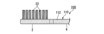
- the toothbrush 100 of the present embodiment includes a handle body 110 having a coating layer 112 formed on the surface of a base 111.
- a substantially semicircular exposed portion 114 is formed near the head portion tip 21, and a substantially square exposed portion 116 is formed near the head portion base end.
- a substantially rectangular exposed portion 118 is formed on the bottom surface of the neck portion 4 so as to extend from the head portion base end to the handle portion base end in the direction of the axis O1.
- the exposed portion 118 is substantially flush with the outer surface of the covering layer 112.
- the exposed portion 114 and the exposed portion 116 are also substantially flush with the outer surface of the coating layer 112, similar to the exposed portion 118.
- the region where the base 111 is exposed is not formed in a region that is symmetrical with the exposed portions 114, 116, and 118 with the axis O1 as the axis of symmetry.
- the length l1 of the exposed portion 114 can be determined in consideration of the length of the head portion 2 and the like, and is, for example, 5 to 15 mm.
- the width w1 of the exposed portion 114 can be determined in consideration of the width of the head portion 2, and is set to 3 to 8 mm, for example.
- the length l2 of the exposed portion 116 can be determined in consideration of the length of the head portion 2 and the like, and is set to 3 to 5 mm, for example.
- the width of the exposed portion 116 is the same as the width w1 of the exposed portion 114.
- the width w2 of the exposed portion 118 can be determined in consideration of the width of the neck portion 4 and the like, and is, for example, 1 to 4 mm.
- FIGS. 3A to 3D A toothbrush according to a third embodiment of the present invention will be described with reference to FIGS. 3A to 3D.
- the same components as those in the first embodiment are denoted by the same reference numerals, description thereof is omitted, and differences from the first embodiment are mainly described.
- the difference from the first embodiment is the shape of the exposed portion and the position of the exposed portion.
- FIGS. 4A to 4D A toothbrush according to a fourth embodiment of the present invention will be described with reference to FIGS. 4A to 4D.
- the same components as those in the first embodiment are denoted by the same reference numerals, description thereof is omitted, and differences from the first embodiment are mainly described.
- This embodiment is different from the first embodiment in that a substantially rectangular exposed portion is formed on the bottom surface of the neck portion.
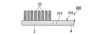
- the toothbrush 300 of the present embodiment includes a handle body 310 having a coating layer 312 formed on the surface of a base 311.
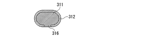
- the covering layer 312 three exposed portions 14 are formed on the bottom surface of the head portion 2, and one substantially rectangular exposed portion 316 whose longitudinal direction is the axis O 1 direction is formed on the bottom surface of the neck portion 4.
- the exposed portion 316 is substantially flush with the outer surface of the covering layer 312.
- an area where the base 311 is exposed is not formed in an area symmetrical to the exposed portion 316 with the axis O1 as the axis of symmetry.
- the length l3 of the exposed portion 316 can be determined in consideration of the length of the head portion 2 and the like, and is set to 1 to 5 mm, for example.
- the width w4 of the exposed portion 316 can be determined in consideration of the width of the neck portion 4 and the like, and is, for example, 1 to 4 mm.
- the base can be more stably fixed in the secondary mold.
- the exposed portion is formed only on the surface (bottom surface) opposite to the flocked surface, but the present invention is not limited to this, and is a surface facing in the same direction as the flocked surface ( An exposed portion may be formed on the upper surface) or the side surface. Alternatively, the exposed portion may be formed on any two or more of the bottom surface, the top surface, and the side surface. When the exposed portion is formed on any two or more of the bottom surface, the top surface, and the side surface, the base can be more stably fixed in the secondary mold.
- the substantially true circular exposed portion is formed in the head portion, but the present invention is not limited to this, and the shape of the exposed portion is elliptical, substantially polygonal, or the like. It may be.
- a substantially polygon is a concept including a shape in which corners are cut off by straight lines or curves.
- the shape of the exposed portion is preferably a circle such as a perfect circle or an ellipse, or a polygon cut off by a curve, in order to suppress peeling of the coating layer.
- the shape of the exposed portion formed in the neck portion is substantially rectangular, but the present invention is not limited to this, and the shape of the exposed portion formed in the neck portion is circular. It may be.
- the number of exposed portions 14, 114, 116, 118, 214, or 316 is 1, 3, or 4, but the present invention is not limited to this.
- the number of the exposed portions 14, 114, 116, 118, 214, or 316 can be determined according to the design, and is preferably 1 to 5, more preferably 2 to 4.
- the coating layer is formed in the region including the handle portion proximal end from the head portion distal end.
- the coating layer only needs to cover 70% or more of the total surface area of the head portion and the surface area of the neck portion.
- the coating layer is formed from the front end of the head portion to the front end of the handle portion.
- a coating layer may be formed up to the tip of the handle portion.
- Example 1 The base material shown in Table 1 is used as a primary resin, the base is manufactured, and then the coating layer material shown in Table 1 is used as a secondary resin to form a coating layer on the base.
- a toothbrush similar to 100 was produced. About the obtained toothbrush, head part intensity
- “polyester” indicates a polyester elastomer
- polyolefin indicates a polyolefin elastomer
- Example 2 A toothbrush similar to the toothbrush 200 of FIGS. 3A to 3D was manufactured in the same manner as in Example 1 except that the base material and the coating layer material were as shown in Table 1 and the exposed part was the following specification. About the obtained toothbrush, head part intensity
- Example 3 A toothbrush similar to the toothbrush 300 of FIGS. 4A to 4D was manufactured in the same manner as in Example 1 except that the base material and the coating layer material were as shown in Table 1 and the exposed portion was the following specification. About the obtained toothbrush, head part intensity
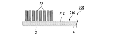
- Example 1 A toothbrush similar to the toothbrush 700 of FIGS. 5A to 5D was produced in the same manner as in Example 1 except that the base material and the coating layer material were those shown in Table 1. About the obtained toothbrush, head part intensity
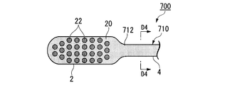
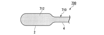
- the toothbrush 700 includes a handle body 710 in which the entire base 711 is covered with a coating layer 712. In the handle body 710, 100% of the total surface area of the head portion 2 and the neck portion 4 is covered with the coating layer 712, and no exposed portion is formed.
- Example 2 A toothbrush similar to the toothbrush 800 of FIGS. 6A to 6D was manufactured in the same manner as in Example 1 except that the base material was as shown in Table 1 and secondary molding was not performed. About the obtained toothbrush, head part intensity
- the toothbrush 800 does not have a coating layer formed on the handle body 810, and is constituted only by a base.
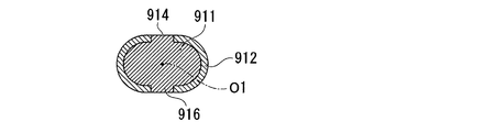
- the toothbrush 900 includes a handle body 910 having a coating layer 912 formed on the surface of a base 911.
- a substantially rectangular exposed portion 914 is formed on the upper surface of the neck portion 4, and a substantially rectangular exposed portion 916 is formed on the bottom surface of the neck portion 4.
- the exposed portion 914 and the exposed portion 916 are formed in a two-fold symmetric region with the axis O1 as the axis of symmetry.
- Example 1 As shown in Table 1, in each of Examples 1 to 3 to which the present invention was applied, the overall evaluation was “B” or “A”. In Examples 1 to 3, operability and usability in the oral cavity were all good. On the other hand, Comparative Example 1 in which no exposed part was formed had a moldability of “D”, and Comparative Example 2 in which no coating layer was formed showed separation of the handle body. In Comparative Example 3 in which the axis of the neck portion was the axis of symmetry and the exposed portion was formed in a region that was twice symmetric, the neck portion strength was “C”. From the above results, it was found that by applying the present invention, it is possible to obtain a toothbrush that can prevent the head portion and the neck portion from being broken or broken and can be easily manufactured.
- the present invention it is possible to provide a toothbrush that can prevent the head portion and the neck portion from being broken or broken and can be easily manufactured.
- Handle part 10 110, 210, 310 Handle body 11, 111, 211, 311 Base 12, 112, 212, 312 Coating layer 14, 114, 116, 118, 214, 316 exposed portion 20 flocked surface 22 hair bundle O1 axis
Landscapes
- Brushes (AREA)
Abstract
本発明は、植毛面(20)に2以上の毛束(22)が植毛されたヘッド部(2)と、前記ヘッド部(2)に延設されたネック部(4)と、前記ネック部(4)に延設されたハンドル部(6)とを備えるハンドル体(10)を備え、前記ハンドル体(10)には、硬質樹脂で構成された基台(11)の表面に、前記ヘッド部(2)の表面積と前記ネック部(4)の表面積との合計の70%以上を覆う軟質樹脂からなる被覆層(12)が形成された歯ブラシ(1)において、前記被覆層(12)には、前記基台(11)が露出した露出部(14)が1以上形成され、前記ネック部(4)の軸線(O1)を対称軸とした2回対称の領域に露出部(14)が形成されていない歯ブラシ(1)に関する。本発明によれば、ヘッド部及びネック部の欠損や折れを防止でき、かつ容易に製造できる歯ブラシを提供することができる。
Description
本発明は、歯ブラシに関する。
本願は2011年6月20日に日本に出願された、特願2011-136480号に基づき優先権を主張し、その内容をここに援用する。
本願は2011年6月20日に日本に出願された、特願2011-136480号に基づき優先権を主張し、その内容をここに援用する。
歯ブラシとしては、ハンドル体の先端近傍に2以上の用毛を束ねた毛束が植毛されたものが知られている。一般に、ハンドル体は、毛束が植毛されるヘッド部と、ネック部を介してヘッド部に延設されたハンドル部とを備え、全体として長尺状の形状とされている。
ヘッド部は、口腔内での操作性が考慮され、できるだけ薄く成形されることが多い。また、ネック部は、口腔内での操作性が考慮され、ヘッド部より縮径された形状とされていることが多い。
ヘッド部は、口腔内での操作性が考慮され、できるだけ薄く成形されることが多い。また、ネック部は、口腔内での操作性が考慮され、ヘッド部より縮径された形状とされていることが多い。
一般に、ハンドル体は、ポリプロピレン等の硬質樹脂で構成されているが、口腔内を清掃する際にヘッド部やネック部を強く噛んだりして過度な負担を掛けると、ヘッド部やネック部が折れたり、一部が欠損したりすることがある。
ヘッド部又はネック部の強度を高めるために、ヘッド部やネック部の厚みを増したり、ネック部の径を大きくしたりすると、口腔内での操作性が損なわれる。
あるいは、ネック部にリブ等を形成してネック部の強度を高めると、リブが口腔内に接触するため、使用感が損なわれる。
あるいは、ネック部にリブ等を形成してネック部の強度を高めると、リブが口腔内に接触するため、使用感が損なわれる。
こうした問題に対し、例えば、ヘッド部及びネック部の一方の面、又はハンドル体の全面をエラストマー樹脂等の軟質樹脂で被覆した歯ブラシが提案されている(例えば、特許文献1)。
しかしながら、特許文献1の技術のように、単にヘッド部及びネック部を軟質樹脂で被覆すると、ハンドル体の芯となる硬質樹脂の体積が小さくなり、強度が低下する。
硬質樹脂の体積を大きくすると、ヘッド部やネック部が厚くなり、操作性や使用感が損なわれやすい。
加えて、ヘッド部及びネック部の一方の面だけを軟質樹脂で被覆しても、ヘッド部及びネック部の欠損や折れを十分に防止できない。
ハンドル体を軟質樹脂で被覆するには、ハンドル体の芯を硬質樹脂で成形し(一次成形)、これを金型に入れ、金型内に軟質樹脂を射出する(二次成形)。このため、二次成形において、軟質樹脂を射出した際に、芯の姿勢が動き、安定した厚みで軟質樹脂を被覆しにくいという問題がある。特に、ハンドル体の全面を安定した厚みの軟質樹脂で被覆するのは困難である。
そこで、本発明は、ヘッド部及びネック部の欠損や折れを防止でき、かつ容易に製造できる歯ブラシの提供を目的とする。
硬質樹脂の体積を大きくすると、ヘッド部やネック部が厚くなり、操作性や使用感が損なわれやすい。
加えて、ヘッド部及びネック部の一方の面だけを軟質樹脂で被覆しても、ヘッド部及びネック部の欠損や折れを十分に防止できない。
ハンドル体を軟質樹脂で被覆するには、ハンドル体の芯を硬質樹脂で成形し(一次成形)、これを金型に入れ、金型内に軟質樹脂を射出する(二次成形)。このため、二次成形において、軟質樹脂を射出した際に、芯の姿勢が動き、安定した厚みで軟質樹脂を被覆しにくいという問題がある。特に、ハンドル体の全面を安定した厚みの軟質樹脂で被覆するのは困難である。
そこで、本発明は、ヘッド部及びネック部の欠損や折れを防止でき、かつ容易に製造できる歯ブラシの提供を目的とする。
本発明の1つの側面としては、植毛面に2以上の毛束が植毛されたヘッド部と、前記ヘッド部に延設されたネック部と、前記ネック部に延設されたハンドル部とを備えるハンドル体を備え、前記ハンドル体には、硬質樹脂で構成された基台の表面に、前記ヘッド部の表面積と前記ネック部の表面積との合計の70%以上を覆う軟質樹脂からなる被覆層が形成された歯ブラシにおいて、前記被覆層には、前記基台が露出した露出部が1以上形成され、前記ネック部の軸線を対称軸とした線対称の領域に露出部が形成されていないことを特徴とする歯ブラシに関する。
本発明の別の側面としては、前記硬質樹脂は、ポリブチレンテレフタレートであることが好ましい。
本発明の別の側面としては、前記硬質樹脂は、ポリブチレンテレフタレートであることが好ましい。
すなわち、本発明は以下に関する。
(1)植毛面に2以上の毛束が植毛されたヘッド部と、前記ヘッド部に延設されたネック部と、前記ネック部に延設されたハンドル部とを備えるハンドル体を備え、前記ハンドル体には、硬質樹脂で構成された基台の表面に、前記ヘッド部の表面積と前記ネック部の表面積との合計の70%以上を覆う軟質樹脂からなる被覆層が形成された歯ブラシにおいて、前記被覆層には、前記基台が露出した露出部が1以上形成され、前記露出部は前記ネック部の長手方向の軸線を対称軸とした2回対称の領域に形成されていない歯ブラシ。
(2)前記硬質樹脂は、ポリブチレンテレフタレートである、(1)に記載の歯ブラシ。
(3)前記ハンドル体に、前記ヘッド部の表面積と前記ネック部の表面積との合計の70%以上95%以下を覆う前記被覆層が形成された、(1)又は(2)に記載の歯ブラシ。
(1)植毛面に2以上の毛束が植毛されたヘッド部と、前記ヘッド部に延設されたネック部と、前記ネック部に延設されたハンドル部とを備えるハンドル体を備え、前記ハンドル体には、硬質樹脂で構成された基台の表面に、前記ヘッド部の表面積と前記ネック部の表面積との合計の70%以上を覆う軟質樹脂からなる被覆層が形成された歯ブラシにおいて、前記被覆層には、前記基台が露出した露出部が1以上形成され、前記露出部は前記ネック部の長手方向の軸線を対称軸とした2回対称の領域に形成されていない歯ブラシ。
(2)前記硬質樹脂は、ポリブチレンテレフタレートである、(1)に記載の歯ブラシ。
(3)前記ハンドル体に、前記ヘッド部の表面積と前記ネック部の表面積との合計の70%以上95%以下を覆う前記被覆層が形成された、(1)又は(2)に記載の歯ブラシ。
本発明の歯ブラシによれば、ヘッド部及びネック部の欠損や折れを防止でき、かつ容易に製造できる。
(第一の実施形態)
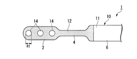
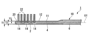
本発明の第一の実施形態にかかる歯ブラシについて、以下に図1A~図1Cを用いて説明する。
図1A~図1Cに示す歯ブラシ1は、ヘッド部2と、ヘッド部2に延設されたネック部4と、ネック部4に延設されたハンドル部6とを備えるハンドル体10と、ヘッド部2の植毛面20に植毛された2以上の毛束22とを備えるものである。
毛束22の数は、清掃力の観点から2以上40以下が好ましく、10以上30以下がより好ましい。
本発明の第一の実施形態にかかる歯ブラシについて、以下に図1A~図1Cを用いて説明する。
図1A~図1Cに示す歯ブラシ1は、ヘッド部2と、ヘッド部2に延設されたネック部4と、ネック部4に延設されたハンドル部6とを備えるハンドル体10と、ヘッド部2の植毛面20に植毛された2以上の毛束22とを備えるものである。
毛束22の数は、清掃力の観点から2以上40以下が好ましく、10以上30以下がより好ましい。
ヘッド部2の平面視形状は、ヘッド部先端21からネック部4に向かう方向を長手とする略長方形であり、その四隅が曲線で隅切された形状とされている。ネック部4は、平面視においてヘッド部基端からハンドル部6に向かい、縮幅した後に略同等の幅で延び、次いで拡幅しハンドル部6に接続されている。ハンドル部6は、ハンドル部基端から略同じ太さで延設されている。
本実施形態におけるヘッド部基端、即ちヘッド部2とネック部4との境界は、ヘッド部2の平面視形状の隅切を形成する曲線の終点(即ち、隅切を形成する曲線の曲がり方向が変化する位置)P1である(図1A参照)。
本実施形態におけるハンドル部基端、即ちネック部4とハンドル部6との境界は、平面視において、ネック部4の拡幅が終了する位置(ネック部終点)P2である(図1A参照)。
本実施形態におけるヘッド部基端、即ちヘッド部2とネック部4との境界は、ヘッド部2の平面視形状の隅切を形成する曲線の終点(即ち、隅切を形成する曲線の曲がり方向が変化する位置)P1である(図1A参照)。
本実施形態におけるハンドル部基端、即ちネック部4とハンドル部6との境界は、平面視において、ネック部4の拡幅が終了する位置(ネック部終点)P2である(図1A参照)。
ヘッド部2の幅W1は、口腔内での操作性等を勘案して決定でき、例えば、8~12mmとされる。
ヘッド部2の長さL1は、口腔内での操作性等を勘案して決定でき、例えば、15~30mmとされる。
ヘッド部2の厚みT1は、口腔内での操作性やハンドル体10に求める強度等を勘案して決定でき、例えば、3~5mmとされる。
ヘッド部2の長さL1は、口腔内での操作性等を勘案して決定でき、例えば、15~30mmとされる。
ヘッド部2の厚みT1は、口腔内での操作性やハンドル体10に求める強度等を勘案して決定でき、例えば、3~5mmとされる。
ハンドル体10は、基台11と、基台11の表面を覆う被覆層12とを備え、被覆層12は、ヘッド部先端21から、ハンドル部基端よりもハンドル部6の先端寄りにかけて形成されている。被覆層12には、基台11が露出した3つの露出部14が形成され、露出部14は、略真円形とされ、被覆層12の外面と略面一とされている。
また、ネック部4の軸線O1を対称軸とし、任意の露出部14と2回対称の領域には、基台11が露出した領域が形成されていない。即ち、本実施形態においては、ヘッド部2の表面の内、植毛面20と反対側の面(底面)にのみ露出部14が形成されている。
軸線O1は、ヘッド部基端とハンドル部基端とを結び、かつネック部4の長手方向に対して垂直な任意の断面の中心を通る線である。
また、ネック部4の軸線O1を対称軸とし、任意の露出部14と2回対称の領域には、基台11が露出した領域が形成されていない。即ち、本実施形態においては、ヘッド部2の表面の内、植毛面20と反対側の面(底面)にのみ露出部14が形成されている。
軸線O1は、ヘッド部基端とハンドル部基端とを結び、かつネック部4の長手方向に対して垂直な任意の断面の中心を通る線である。
基台11は、ハンドル体10の芯となる部材であり、ヘッド部2、ネック部4及びハンドル部6を形成する部分が一体成形されたものである。
基台11の材質としては、歯ブラシ1に求める剛性や機械特性等を勘案して決定でき、例えば、曲げ弾性率(JIS K7203)が500~3000MPaの範囲にある硬質樹脂が挙げられる。このような硬質樹脂としては、例えば、ポリプロピレン(PP)、ポリエチレンテレフタレート(PET)、ポリブチレンテレフタレート(PBT)、ポリシクロへキシレンジメチレンテレフタレート(PCT)、ポリアセタール(POM)、ポリスチレン(PS)、アクリロニトリル・ブタジエン・スチレン樹脂(ABS)、セルロースプロピオネート(CP)、ポリアリレート、ポリカーボネート、又はアクリロニトリル・スチレン共重合樹脂(AS)等が挙げられ、中でもPBTが好ましい。PBTは、折れ強度が高いため、ハンドル体10が折れたり、一部が欠損したりするのをより防止できる。前記硬質樹脂は1種単独で又は2種以上を適宜組み合わせて用いることができる。
基台11の材質としては、歯ブラシ1に求める剛性や機械特性等を勘案して決定でき、例えば、曲げ弾性率(JIS K7203)が500~3000MPaの範囲にある硬質樹脂が挙げられる。このような硬質樹脂としては、例えば、ポリプロピレン(PP)、ポリエチレンテレフタレート(PET)、ポリブチレンテレフタレート(PBT)、ポリシクロへキシレンジメチレンテレフタレート(PCT)、ポリアセタール(POM)、ポリスチレン(PS)、アクリロニトリル・ブタジエン・スチレン樹脂(ABS)、セルロースプロピオネート(CP)、ポリアリレート、ポリカーボネート、又はアクリロニトリル・スチレン共重合樹脂(AS)等が挙げられ、中でもPBTが好ましい。PBTは、折れ強度が高いため、ハンドル体10が折れたり、一部が欠損したりするのをより防止できる。前記硬質樹脂は1種単独で又は2種以上を適宜組み合わせて用いることができる。
ヘッド部2における基台11の厚みT2は、基台11の材質等を勘案して決定でき、例えば、2~4mmとされる。
ネック部4における基台11の厚みは、ヘッド部11における基台11の厚みT2と同様である。
ネック部4における基台11の厚みは、ヘッド部11における基台11の厚みT2と同様である。
被覆層12は、ヘッド部2の表面積とネック部4の表面積との合計の70%以上を覆う(被覆率70%)ものであり、例えば、70~95%を覆うものが好ましく、80~90%を覆うものがより好ましい。被覆層12による被覆率が高まるほど、ヘッド部及びネック部の欠損や折れをより高度に防止できる。
ヘッド部2の表面積とは、ヘッド部先端21からヘッド部基端まで、すなわちヘッド部先端21からヘッド部2とネック部4との境界であるP1までの正面(植毛面20)からの投影面積である。
ネック部4の表面積とは、前記P1からネック部4の拡幅が終了する位置(ネック部終点)P2までの正面(植毛面20)からの投影面積である。
ヘッド部2の表面積とは、ヘッド部先端21からヘッド部基端まで、すなわちヘッド部先端21からヘッド部2とネック部4との境界であるP1までの正面(植毛面20)からの投影面積である。
ネック部4の表面積とは、前記P1からネック部4の拡幅が終了する位置(ネック部終点)P2までの正面(植毛面20)からの投影面積である。
被覆層12の材質は、ハンドル体の破損等を防止できる軟質樹脂であればよく、例えば、ポリオレフィン系エラストマー、スチレン系エラストマー、又はポリエステル系エラストマー等のエラストマー樹脂が挙げられ、中でも、基台11の欠損をより確実に防ぐ観点からスチレン系エラストマーが好ましい。スチレン系エラストマーとしては、例えば、セプトン(商品名、株式会社クラレ製)、又はレオストマー(商品名、リケンテクノス株式会社製)等が挙げられる。
被覆層12の材質は、基台11の材質を勘案して決定することがより好ましい。
例えば、基台11の材質がPBTであれば、被覆層12の材質は、スチレン系エラストマー、又はポリエステル系エラストマーが好ましく、ポリエステル系エラストマーがより好ましい。また、基台11の材質がPPであれば、ポリオレフィン系エラストマー、又はスチレン系エラストマーが好ましく、ポリオレフィン系エラストマーがより好ましい。基台11の材質と被覆層12の材質とをこのような組み合わせとすることで、基台11から被覆層12が剥離するのをより低減できる。
被覆層12の材質は、基台11の材質を勘案して決定することがより好ましい。
例えば、基台11の材質がPBTであれば、被覆層12の材質は、スチレン系エラストマー、又はポリエステル系エラストマーが好ましく、ポリエステル系エラストマーがより好ましい。また、基台11の材質がPPであれば、ポリオレフィン系エラストマー、又はスチレン系エラストマーが好ましく、ポリオレフィン系エラストマーがより好ましい。基台11の材質と被覆層12の材質とをこのような組み合わせとすることで、基台11から被覆層12が剥離するのをより低減できる。
被覆層12の厚みT3は、被覆層12を構成する樹脂の材質等を勘案して決定でき、例えば、0.5~2mmが好ましく、0.8~1.5mmがより好ましい。上記下限値以上であると、ハンドル体10の破損を有効に防止でき、上記上限値以下であると、ヘッド部2又はネック部4の厚みが厚くなりすぎず、ハンドル体10の操作性が向上する。
露出部14の直径R1は、特に限定されず、ヘッド部2の大きさ等を勘案して決定できる。
[露出部の面積の合計]/[被覆面積]で表される露出比は、被覆層12の被覆率等を勘案して決定でき、0.05~0.3が好ましく、0.1~0.2がより好ましい。上記下限値以上であると、後述する二次成形において二次金型内で基台を固定しやすくなり、上記上限値以下であると、被覆層12が剥離しにくくなる。
被覆面積とは、被覆層12の面積と露出部14の面積との合計である。
[露出部の面積の合計]/[被覆面積]で表される露出比は、被覆層12の被覆率等を勘案して決定でき、0.05~0.3が好ましく、0.1~0.2がより好ましい。上記下限値以上であると、後述する二次成形において二次金型内で基台を固定しやすくなり、上記上限値以下であると、被覆層12が剥離しにくくなる。
被覆面積とは、被覆層12の面積と露出部14の面積との合計である。
毛束22は、2以上40以下の用毛を束ねたものである。
植毛面20から毛束22の先端までの長さ(毛丈)は、毛束22に求める毛腰等を勘案して決定でき、例えば、6~13mmとされる。
全ての毛束22は同じ毛丈であってもよいし、相互に異なっていてもよい。
植毛面20から毛束22の先端までの長さ(毛丈)は、毛束22に求める毛腰等を勘案して決定でき、例えば、6~13mmとされる。
全ての毛束22は同じ毛丈であってもよいし、相互に異なっていてもよい。
毛束22の太さ(毛束径)は、毛束22に求める毛腰等を勘案して決定でき、例えば、1~2mmとされる。全ての毛束22は同じ毛束径であってもよいし、相互に異なっていてもよい。
毛束22を構成する用毛としては、例えば、毛先に向かって漸次その径が小さくなり、毛先が先鋭化された用毛(テーパー毛)、又は植毛面20から毛先に向かいその径がほぼ同一である用毛(ストレート毛)等が挙げられる。ストレート毛としては、毛先が植毛面20に略平行な平面とされたものや、毛先が半球状に丸められたものが挙げられる。
用毛の材質は、例えば、6-12ナイロン(6-12NY)、若しくは6-10ナイロン(6-10NY)等のポリアミド、PET、PBT、ポリトリメチレンテレフタレート(PTT)、ポリエチレンナフタレート(PEN)、若しくはポリブチレンナフタレート(PBN)等のポリエステル、PP等のポリオレフィン、又はポリオレフィン系エラストマー、若しくはスチレン系エラストマー等のエラストマー樹脂等が挙げられる。
これらの樹脂材料は、1種単独で又は2種以上を組み合わせて用いることができる。
また、用毛としては、芯部と前記芯部の外側に設けられた少なくとも1層以上の鞘部とを有する多重芯構造を有するポリエステル製用毛が挙げられる。
これらの樹脂材料は、1種単独で又は2種以上を組み合わせて用いることができる。
また、用毛としては、芯部と前記芯部の外側に設けられた少なくとも1層以上の鞘部とを有する多重芯構造を有するポリエステル製用毛が挙げられる。
用毛の横断面形状は、特に限定されず、真円形、若しくは楕円形等の円形、多角形、星形、三つ葉のクローバー形、又は四つ葉のクローバー形等としてもよい。全ての用毛の断面形状は同じであってもよいし、異なっていてもよい。
用毛の太さは、材質等を勘案して決定でき、横断面が円形の場合、例えば、6~9mil(1mil=1/1000inch=0.025mm)とされる。また、使用感、刷掃感、清掃効果、又は耐久性等考慮して、太さの異なる2本以上の用毛を任意に組み合わせて用いてもよい。
歯ブラシ1の製造方法は、例えば、基台11を成形し(一次成形)、得られた基台11に被覆層12を形成する(二次成形)成形工程と、次いでヘッド部2に毛束22を植毛する植毛工程とを備える方法が挙げられる。
一次成形は、基台11の形状に対応するキャビティを形成する一対の一次金型を用い、前記キャビティに基台11を構成する硬質樹脂(一次樹脂ということがある)を射出して、基台11を成形する操作である。
続く二次成形は、被覆層12の形状に対応するキャビティが形成された一対の二次金型を用い、一次成形で得られた基台11を二次金型のキャビティ内に装填し、二次金型に被覆層12を構成する軟質樹脂(二次樹脂ということがある)を射出し、被覆層12を形成する操作である。二次金型のキャビティは、キャビティ内に基台11が装填された際、装填された基台11とキャビティとの間に形成された空間が、被覆層12に対応する形状とされたものである。
二次成形の際、基台11には、露出部14に対応する形状の凸部が形成されており、この凸部が二次金型の内面に当接する。このため、二次金型の内部には、被覆層12に対応する形状の隙間が安定的に形成される。加えて、二次樹脂を射出した際にも、被覆層12に対応した形状の隙間が確保されるため、被覆層12を所望した厚みで、安定的に形成できる。
二次成形の際、基台11には、露出部14に対応する形状の凸部が形成されており、この凸部が二次金型の内面に当接する。このため、二次金型の内部には、被覆層12に対応する形状の隙間が安定的に形成される。加えて、二次樹脂を射出した際にも、被覆層12に対応した形状の隙間が確保されるため、被覆層12を所望した厚みで、安定的に形成できる。
植毛工程は、ヘッド部2に毛束22を植毛し、歯ブラシ1とする工程である。毛束22の植毛方法は、公知の方法を用いることができ、例えば、2本以上の用毛からなる毛束を二つ折りにし、その間に抜け止め部材(平線)を挟み、この平線を植毛穴に打ち込んで毛束を固定する平線植毛法が挙げられる。この平線は、従来公知のものを用いることができ、例えば、真鍮製、又はアルミニウム製の平板状のものが挙げられる。
上述した通り、本実施形態の歯ブラシによれば、硬質樹脂で構成された基台の表面に、ヘッド部の表面積とネック部の表面積との合計の70%以上を覆う軟質樹脂からなる被覆層が形成されているため、ヘッド部やネック部に過度な負担を掛けても、ハンドル体が折れにくい。また、ヘッド部又はネック部においてハンドル体が折れた場合でも、折れた部分が露出するのを防止したり、欠落した部材を被覆層で保持したりできる。
本実施形態の歯ブラシによれば、被覆層には、基台が露出した露出部が1以上形成されているため、被覆層を所望する厚さで安定的に形成できる。
本実施形態の歯ブラシによれば、ネック部の軸線を対称軸とした2回対称の領域に露出部が形成されていないため、ヘッド部又はネック部を歯で噛んだ際に、上顎歯及び下顎歯のいずれかは露出部に直接接することがない。加えて、ヘッド部又はネック部にいずれの方向から荷重が掛けられた場合でも、被覆層により荷重を緩和できる。このため、ヘッド部又はネック部に過度な負担が掛かるのを防止し、ヘッド部及びネック部の欠損や折れを防止できる。
本実施形態の歯ブラシによれば、被覆層には、基台が露出した露出部が1以上形成されているため、被覆層を所望する厚さで安定的に形成できる。
本実施形態の歯ブラシによれば、ネック部の軸線を対称軸とした2回対称の領域に露出部が形成されていないため、ヘッド部又はネック部を歯で噛んだ際に、上顎歯及び下顎歯のいずれかは露出部に直接接することがない。加えて、ヘッド部又はネック部にいずれの方向から荷重が掛けられた場合でも、被覆層により荷重を緩和できる。このため、ヘッド部又はネック部に過度な負担が掛かるのを防止し、ヘッド部及びネック部の欠損や折れを防止できる。
(第二の実施形態)
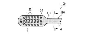
本発明の第二の実施形態にかかる歯ブラシについて、図2A~図2Dを用いて説明する。第一の実施形態と同一の構成には同一の符号を付してその説明を省略すると共に、主に第一の実施形態と異なる点について説明する。本実施形態において第一の実施形態と異なる点は、露出部の形状及び露出部の位置である。
本発明の第二の実施形態にかかる歯ブラシについて、図2A~図2Dを用いて説明する。第一の実施形態と同一の構成には同一の符号を付してその説明を省略すると共に、主に第一の実施形態と異なる点について説明する。本実施形態において第一の実施形態と異なる点は、露出部の形状及び露出部の位置である。
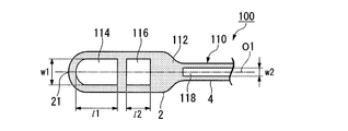
本実施形態の歯ブラシ100は、基台111の表面に被覆層112が形成されたハンドル体110を備えるものである。ヘッド部2の底面には、略半円形の露出部114がヘッド部先端21寄りに形成され、略四角形の露出部116がヘッド部基端寄りに形成されている。また、ネック部4の底面には、ヘッド部基端からハンドル部基端に掛けて軸線O1方向に伸びる略長方形の露出部118が形成されている。
図2Dに示すように、露出部118は、被覆層112の外面と略面一とされている。露出部114及び露出部116も露出部118と同様に被覆層112の外面と略面一とされている。
また、軸線O1を対称軸とし、露出部114、116及び118と2回対称の領域には、基台111が露出した領域が形成されていない。
図2Dに示すように、露出部118は、被覆層112の外面と略面一とされている。露出部114及び露出部116も露出部118と同様に被覆層112の外面と略面一とされている。
また、軸線O1を対称軸とし、露出部114、116及び118と2回対称の領域には、基台111が露出した領域が形成されていない。
露出部114の長さl1は、ヘッド部2の長さ等を勘案して決定でき、例えば、5~15mmとされる。露出部114の幅w1は、ヘッド部2の幅を勘案して決定でき、例えば、3~8mmとされる。
露出部116の長さl2は、ヘッド部2の長さ等を勘案して決定でき、例えば、3~5mmとされる。露出部116の幅は、露出部114の幅w1と同様である。
露出部118の幅w2は、ネック部4の幅等を勘案して決定でき、例えば、1~4mmとされる。
露出部116の長さl2は、ヘッド部2の長さ等を勘案して決定でき、例えば、3~5mmとされる。露出部116の幅は、露出部114の幅w1と同様である。
露出部118の幅w2は、ネック部4の幅等を勘案して決定でき、例えば、1~4mmとされる。
本実施形態によれば、ヘッド部及びネック部に露出部が形成されているため、二次金型内で基台をより安定して固定できる。
(第三の実施形態)
本発明の第三の実施形態にかかる歯ブラシについて、図3A~図3Dを用いて説明する。第一の実施形態と同一の構成には同一の符号を付してその説明を省略すると共に、主に第一の実施形態と異なる点について説明する。本実施形態において第一の実施形態と異なる点は、露出部の形状及び露出部の位置である。
本発明の第三の実施形態にかかる歯ブラシについて、図3A~図3Dを用いて説明する。第一の実施形態と同一の構成には同一の符号を付してその説明を省略すると共に、主に第一の実施形態と異なる点について説明する。本実施形態において第一の実施形態と異なる点は、露出部の形状及び露出部の位置である。
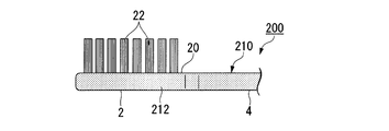
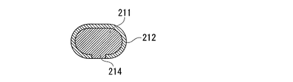
本実施形態の歯ブラシ200は、基台211の表面に被覆層212が形成されたハンドル体210を備えるものである。被覆層212には、底面にヘッド部2からネック部4にかけて、軸線O1方向に伸びる略長方形の露出部214が形成されている。
図3Dに示すように、露出部214は、被覆層212の外面と略面一とされている。
また、軸線O1を対称軸とし、露出部214と2回対称の領域には、基台211が露出した領域が形成されていない。
図3Dに示すように、露出部214は、被覆層212の外面と略面一とされている。
また、軸線O1を対称軸とし、露出部214と2回対称の領域には、基台211が露出した領域が形成されていない。
露出部214の幅w3は、ネック部4の幅等を勘案して決定でき、例えば、1~4mmとされる。
本実施形態によれば、複雑な形状の露出部を形成する必要がないため、より容易に二次金型内で基台を安定して固定できる。
(第四の実施形態)
本発明の第四の実施形態にかかる歯ブラシについて、図4A~図4Dを用いて説明する。第一の実施形態と同一の構成には同一の符号を付してその説明を省略すると共に、主に第一の実施形態と異なる点について説明する。本実施形態において第一の実施形態と異なる点は、ネック部の底面に略長方形の露出部が形成されている点である。
本発明の第四の実施形態にかかる歯ブラシについて、図4A~図4Dを用いて説明する。第一の実施形態と同一の構成には同一の符号を付してその説明を省略すると共に、主に第一の実施形態と異なる点について説明する。本実施形態において第一の実施形態と異なる点は、ネック部の底面に略長方形の露出部が形成されている点である。
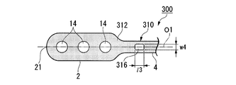
本実施形態の歯ブラシ300は、基台311の表面に被覆層312が形成されたハンドル体310を備えるものである。被覆層312には、ヘッド部2の底面に3つの露出部14が形成されると共に、ネック部4の底面に軸線O1方向を長手とする略長方形の露出部316が1つ形成されている。
図4Dに示すように、露出部316は、被覆層312の外面と略面一とされている。
また、軸線O1を対称軸とし、露出部316と2回対称の領域には、基台311が露出した領域が形成されていない。
図4Dに示すように、露出部316は、被覆層312の外面と略面一とされている。
また、軸線O1を対称軸とし、露出部316と2回対称の領域には、基台311が露出した領域が形成されていない。
露出部316の長さl3は、ヘッド部2の長さ等を勘案して決定でき、例えば、1~5mmとされる。露出部316の幅w4は、ネック部4の幅等を勘案して決定でき、例えば、1~4mmとされる。
本実施形態によれば、ヘッド部及びネック部の双方に露出部が形成されているため、二次金型内で基台をより安定して固定できる。
(その他の実施形態)
本発明は、上述の実施形態に限定されるものではない。
第一~第四の実施形態では、露出部が被覆層の外面と略面一とされているが、本発明は、これに限定されず、露出部が被覆層の外面から突出したものであってもよいし、露出部が被覆層の外面から凹んだものであってもよい。
本発明は、上述の実施形態に限定されるものではない。
第一~第四の実施形態では、露出部が被覆層の外面と略面一とされているが、本発明は、これに限定されず、露出部が被覆層の外面から突出したものであってもよいし、露出部が被覆層の外面から凹んだものであってもよい。
第一~第四の実施形態では、植毛面と反対側の面(底面)にのみ露出部が形成されているが、本発明は、これに限定されず、植毛面と同方向に向く面(上面)又は側面に露出部が形成されていてもよい。あるいは、底面、上面及び側面のいずれか2面以上に露出部が形成されていてもよい。
底面、上面及び側面のいずれか2面以上に露出部が形成されていると、二次金型内で基台をより安定して固定できる。
底面、上面及び側面のいずれか2面以上に露出部が形成されていると、二次金型内で基台をより安定して固定できる。
第一及び第四の実施形態では、ヘッド部に略真円形の露出部が形成されているが、本発明は、これに限定されず、露出部の形状は、楕円形、又は略多角形等であってもよい。略多角形とは、角部が直線又は曲線で隅切された形状を含む概念である。
露出部の形状は、被覆層の剥離を抑制するため、真円形若しくは楕円形等の円形、又は曲線で隅切された多角形であることが好ましい。
露出部の形状は、被覆層の剥離を抑制するため、真円形若しくは楕円形等の円形、又は曲線で隅切された多角形であることが好ましい。
第二~第四の実施形態では、ネック部に形成された露出部の形状が略長方形とされているが、本発明はこれに限定されず、ネック部に形成される露出部の形状が円形であってもよい。
図1B、図2B、図3B又は図4Bでは、露出部14、114、116、118、214又は316の数が1、3又は4個であるが、本発明はこれに限定されない。露出部14、114、116、118、214又は316の数はデザインに応じて決定でき、1~5個が好ましく、2~4個がより好ましい。
第一~第四の実施形態では、被覆層が、ヘッド部先端から、ハンドル部基端を含む領域に形成されている。しかしながら、被覆層は、ヘッド部の表面積とネック部の表面積との合計の70%以上を覆っていればよく、例えば、ヘッド部先端からハンドル部基端の手前までに被覆層が形成されていてもよいし、ハンドル部の先端まで被覆層が形成されていてもよい。
本発明において、毛束の植毛パターンは、特に限定されず、いわゆる格子状、千鳥状及びこれらの組み合わせのいずれであってもよい。
以下、実施例を示して本発明を詳細に説明するが、本発明は以下の記載によって限定されるものではない。
(実施例1)
表1に示す基台材質を一次樹脂として基台を製造し、次いで表1に示す被覆層材質を二次樹脂として基台に被覆層を形成して、下記仕様の図2A~図2Dの歯ブラシ100と同様の歯ブラシを製造した。得られた歯ブラシについて、ヘッド部強度、ネック部強度、分離の有無及び成形性を評価し、その結果を表1に示す。
表中の被覆層の材質において、「ポリエステル系」はポリエステル系エラストマーを示し、「ポリオレフィン系」はポリオレフィン系エラストマーを示し、「スチレン系」はスチレン系エラストマーを示す。
表1に示す基台材質を一次樹脂として基台を製造し、次いで表1に示す被覆層材質を二次樹脂として基台に被覆層を形成して、下記仕様の図2A~図2Dの歯ブラシ100と同様の歯ブラシを製造した。得られた歯ブラシについて、ヘッド部強度、ネック部強度、分離の有無及び成形性を評価し、その結果を表1に示す。
表中の被覆層の材質において、「ポリエステル系」はポリエステル系エラストマーを示し、「ポリオレフィン系」はポリオレフィン系エラストマーを示し、「スチレン系」はスチレン系エラストマーを示す。
<仕様>
ヘッド部幅:8.5mm
ヘッド部長さ:22mm
ヘッド部の厚み:4.5mm
ネック部幅:5mm
ネック部長さ:50mm
露出部114の長さl1:5mm
露出部114の幅w1:4mm
露出部116の長さl2:3mm
露出部118の幅w2:2mm
被覆層の厚み:0.8mm
ヘッド部幅:8.5mm
ヘッド部長さ:22mm
ヘッド部の厚み:4.5mm
ネック部幅:5mm
ネック部長さ:50mm
露出部114の長さl1:5mm
露出部114の幅w1:4mm
露出部116の長さl2:3mm
露出部118の幅w2:2mm
被覆層の厚み:0.8mm
(実施例2)
基台材質及び被覆層材質を表1のものとし、露出部を下記仕様とした以外は、実施例1と同様にして図3A~図3Dの歯ブラシ200と同様の歯ブラシを製造した。得られた歯ブラシについて、ヘッド部強度、ネック部強度、分離の有無及び成形性を評価し、その結果を表1に示す。
基台材質及び被覆層材質を表1のものとし、露出部を下記仕様とした以外は、実施例1と同様にして図3A~図3Dの歯ブラシ200と同様の歯ブラシを製造した。得られた歯ブラシについて、ヘッド部強度、ネック部強度、分離の有無及び成形性を評価し、その結果を表1に示す。
<仕様>
露出部214の幅w3:2mm
露出部214の幅w3:2mm
(実施例3)
基台材質及び被覆層材質を表1のものとし、露出部を下記仕様とした以外は、実施例1と同様にして図4A~図4Dの歯ブラシ300と同様の歯ブラシを製造した。得られた歯ブラシについて、ヘッド部強度、ネック部強度、分離の有無及び成形性を評価し、その結果を表1に示す。
基台材質及び被覆層材質を表1のものとし、露出部を下記仕様とした以外は、実施例1と同様にして図4A~図4Dの歯ブラシ300と同様の歯ブラシを製造した。得られた歯ブラシについて、ヘッド部強度、ネック部強度、分離の有無及び成形性を評価し、その結果を表1に示す。
<仕様>
露出部14の直径:3mm
露出部316の長さl3:3mm
露出部316の幅w4:2mm
露出部14の直径:3mm
露出部316の長さl3:3mm
露出部316の幅w4:2mm
(比較例1)
基台材質及び被覆層材質を表1のものとした以外は、実施例1と同様にして図5A~図5Dの歯ブラシ700と同様の歯ブラシを製造した。得られた歯ブラシについて、ヘッド部強度、ネック部強度、分離の有無及び成形性を評価し、その結果を表1に示す。
歯ブラシ700は、基台711の全体が被覆層712により覆われたハンドル体710を備えるものである。ハンドル体710は、ヘッド部2の表面とネック部4の表面積の合計の100%が被覆層712で覆われており、露出部が形成されていないものである。
基台材質及び被覆層材質を表1のものとした以外は、実施例1と同様にして図5A~図5Dの歯ブラシ700と同様の歯ブラシを製造した。得られた歯ブラシについて、ヘッド部強度、ネック部強度、分離の有無及び成形性を評価し、その結果を表1に示す。
歯ブラシ700は、基台711の全体が被覆層712により覆われたハンドル体710を備えるものである。ハンドル体710は、ヘッド部2の表面とネック部4の表面積の合計の100%が被覆層712で覆われており、露出部が形成されていないものである。
(比較例2)
基台材質を表1のものとし、二次成形をしなかった以外は、実施例1と同様にして図6A~図6Dの歯ブラシ800と同様の歯ブラシを製造した。得られた歯ブラシについて、ヘッド部強度、ネック部強度、分離の有無及び成形性を評価し、その結果を表1に示す。
歯ブラシ800は、ハンドル体810に被覆層が形成されておらず、基台のみで構成されたものである。
基台材質を表1のものとし、二次成形をしなかった以外は、実施例1と同様にして図6A~図6Dの歯ブラシ800と同様の歯ブラシを製造した。得られた歯ブラシについて、ヘッド部強度、ネック部強度、分離の有無及び成形性を評価し、その結果を表1に示す。
歯ブラシ800は、ハンドル体810に被覆層が形成されておらず、基台のみで構成されたものである。
(比較例3)
基台材質及び被覆層材質を表1のものとし、露出部を下記仕様とした以外は、実施例1と同様にして図7A~図7Dの歯ブラシ900と同様の歯ブラシを製造した。得られた歯ブラシについて、ヘッド部強度、ネック部強度、分離の有無及び成形性を評価し、その結果を表1に示す。
歯ブラシ900は、基台911の表面に被覆層912が形成されたハンドル体910を備えるものである。被覆層912には、ネック部4の上面に略長方形の露出部914が形成されると共に、ネック部4の底面に略長方形の露出部916が形成されている。図7Dに示すように、露出部914と露出部916とは、軸線O1を対称軸として2回対称の領域に形成されている。
基台材質及び被覆層材質を表1のものとし、露出部を下記仕様とした以外は、実施例1と同様にして図7A~図7Dの歯ブラシ900と同様の歯ブラシを製造した。得られた歯ブラシについて、ヘッド部強度、ネック部強度、分離の有無及び成形性を評価し、その結果を表1に示す。
歯ブラシ900は、基台911の表面に被覆層912が形成されたハンドル体910を備えるものである。被覆層912には、ネック部4の上面に略長方形の露出部914が形成されると共に、ネック部4の底面に略長方形の露出部916が形成されている。図7Dに示すように、露出部914と露出部916とは、軸線O1を対称軸として2回対称の領域に形成されている。
<仕様>
露出部914の幅w5:2mm
露出部916の幅w6:2mm
露出部914の幅w5:2mm
露出部916の幅w6:2mm
(評価方法)
<ヘッド部強度>
各例の歯ブラシの毛束を切断し、ヘッド部の植毛面を平滑にしたサンプルを用意した。
このサンプルのヘッド部基端をクランプで把持して、サンプルをデジタル衝撃試験機(DG-1型、株式会社東洋精機製作所製)に固定し、植毛面を0.5Jで加重し、ヘッド部が破断したときの吸収エネルギー(J)を測定(n=10)した。この測定値の平均値を下記評価基準に分類し、ヘッド部強度を評価した。
≪評価基準≫
A:0.3J以上
B:0.2J以上0.3J未満
C:0.1J以上0.2J未満
D:0.1J未満
<ヘッド部強度>
各例の歯ブラシの毛束を切断し、ヘッド部の植毛面を平滑にしたサンプルを用意した。
このサンプルのヘッド部基端をクランプで把持して、サンプルをデジタル衝撃試験機(DG-1型、株式会社東洋精機製作所製)に固定し、植毛面を0.5Jで加重し、ヘッド部が破断したときの吸収エネルギー(J)を測定(n=10)した。この測定値の平均値を下記評価基準に分類し、ヘッド部強度を評価した。
≪評価基準≫
A:0.3J以上
B:0.2J以上0.3J未満
C:0.1J以上0.2J未満
D:0.1J未満
<ネック部強度>
各例のサンプルのハンドル部基端をクランプで把持して固定し、植毛面側から2kgで加重し、ネック部が破断したときの破断強度(N)を測定(n=10)した。この測定値の平均値を下記評価基準に分類し、ヘッド部強度を評価した。
≪評価基準≫
A:100N以上
B:70N以上100N未満
C:40N以上70N未満
D:40N未満
各例のサンプルのハンドル部基端をクランプで把持して固定し、植毛面側から2kgで加重し、ネック部が破断したときの破断強度(N)を測定(n=10)した。この測定値の平均値を下記評価基準に分類し、ヘッド部強度を評価した。
≪評価基準≫
A:100N以上
B:70N以上100N未満
C:40N以上70N未満
D:40N未満
<分離の有無>
ヘッド部強度及びネック部強度を測定した後のハンドル体を目視で観察し、ハンドル体の分離の有無を評価した。
B:分離していない。
D:分離している。
ヘッド部強度及びネック部強度を測定した後のハンドル体を目視で観察し、ハンドル体の分離の有無を評価した。
B:分離していない。
D:分離している。
<成形性>
各例の歯ブラシを目視で確認し、軟質樹脂の充填不良(ショートショット)の程度を下記評価基準に従って評価した。各例10個について成形性を評価し、その平均点が4.0点以上を「A」、3.0点以上4.0点未満を「B」、2.0点以上3.0点未満を「C」、2.0点未満を「D」とした。
≪評価基準≫
5:被覆層の厚みが均一で、被覆層の変形や欠けがまったく認められない。
4:被覆層の変形や欠けは認められないが、所定の厚さに達していない領域が被覆層の10%未満の領域に認められる。
3:被覆層の変形や欠けは認められないが、所定の厚さに達していない領域が10%以上50%未満の領域に認められる。
2:被覆層の変形や欠けは認められないが、所定の厚さに達していない領域が50%以上の領域に認められる。
1:被覆層に変形や欠けが認められる。
各例の歯ブラシを目視で確認し、軟質樹脂の充填不良(ショートショット)の程度を下記評価基準に従って評価した。各例10個について成形性を評価し、その平均点が4.0点以上を「A」、3.0点以上4.0点未満を「B」、2.0点以上3.0点未満を「C」、2.0点未満を「D」とした。
≪評価基準≫
5:被覆層の厚みが均一で、被覆層の変形や欠けがまったく認められない。
4:被覆層の変形や欠けは認められないが、所定の厚さに達していない領域が被覆層の10%未満の領域に認められる。
3:被覆層の変形や欠けは認められないが、所定の厚さに達していない領域が10%以上50%未満の領域に認められる。
2:被覆層の変形や欠けは認められないが、所定の厚さに達していない領域が50%以上の領域に認められる。
1:被覆層に変形や欠けが認められる。
<総合評価>
ヘッド部強度、ネック部強度、分離の有無及び成形性の評価結果に基づき、下記評価基準に従って総合評価をした。
≪評価基準≫
A:全ての評価結果が「B」又は「A」で、「A」が2つ以上。
B:全ての評価結果が「B」又は「A」で、「A」が1つ以下。
C:全ての評価結果が「C」、「B」又は「A」で、「C」が1つ以上。
D:評価結果の1つ以上が「D」である。
ヘッド部強度、ネック部強度、分離の有無及び成形性の評価結果に基づき、下記評価基準に従って総合評価をした。
≪評価基準≫
A:全ての評価結果が「B」又は「A」で、「A」が2つ以上。
B:全ての評価結果が「B」又は「A」で、「A」が1つ以下。
C:全ての評価結果が「C」、「B」又は「A」で、「C」が1つ以上。
D:評価結果の1つ以上が「D」である。

表1に示すように、本発明を適用した実施例1~3は、いずれも総合評価が「B」又は「A」であった。また、実施例1~3は、いずれも口腔内での操作性及び使用感が良好であった。
一方、露出部を形成しなかった比較例1は、成形性が「D」であり、被覆層を形成しなかった比較例2は、ハンドル体の分離が認められた。ネック部の軸線を対称軸とし、2回対称となる領域に露出部を形成した比較例3は、ネック部強度が「C」であった。
以上の結果から、本発明を適用することで、ヘッド部及びネック部の欠損や折れを防止でき、かつ容易に製造できる歯ブラシを得られることが判った。
一方、露出部を形成しなかった比較例1は、成形性が「D」であり、被覆層を形成しなかった比較例2は、ハンドル体の分離が認められた。ネック部の軸線を対称軸とし、2回対称となる領域に露出部を形成した比較例3は、ネック部強度が「C」であった。
以上の結果から、本発明を適用することで、ヘッド部及びネック部の欠損や折れを防止でき、かつ容易に製造できる歯ブラシを得られることが判った。
本発明によれば、ヘッド部及びネック部の欠損や折れを防止でき、かつ製造が容易な歯ブラシを提供することが可能である。
1、100、200、300歯ブラシ
2 ヘッド部
4 ネック部
6 ハンドル部
10、110、210、310 ハンドル体
11、111、211、311 基台
12、112、212、312 被覆層
14、114、116、118、214、316露出部
20 植毛面
22 毛束
O1 軸線
2 ヘッド部
4 ネック部
6 ハンドル部
10、110、210、310 ハンドル体
11、111、211、311 基台
12、112、212、312 被覆層
14、114、116、118、214、316露出部
20 植毛面
22 毛束
O1 軸線
Claims (3)
- 植毛面に2以上の毛束が植毛されたヘッド部と、前記ヘッド部に延設されたネック部と、前記ネック部に延設されたハンドル部とを備えるハンドル体を備え、
前記ハンドル体には、硬質樹脂で構成された基台の表面に、前記ヘッド部の表面積と前記ネック部の表面積との合計の70%以上を覆う軟質樹脂からなる被覆層が形成された歯ブラシにおいて、
前記被覆層には、前記基台が露出した露出部が1以上形成され、前記露出部は前記ネック部の長手方向の軸線を対称軸とした2回対称の領域に形成されていない歯ブラシ。 - 前記硬質樹脂は、ポリブチレンテレフタレートである、請求項1に記載の歯ブラシ。
- 前記ハンドル体に、前記ヘッド部の表面積と前記ネック部の表面積との合計の70%以上95%以下を覆う前記被覆層が形成された、請求項1又は2に記載の歯ブラシ。
Priority Applications (2)
| Application Number | Priority Date | Filing Date | Title |
|---|---|---|---|
| KR1020137030615A KR102085517B1 (ko) | 2011-06-20 | 2012-06-18 | 칫솔 |
| CN201280014091.3A CN103442614B (zh) | 2011-06-20 | 2012-06-18 | 牙刷 |
Applications Claiming Priority (2)
| Application Number | Priority Date | Filing Date | Title |
|---|---|---|---|
| JP2011-136480 | 2011-06-20 | ||
| JP2011136480A JP5830277B2 (ja) | 2011-06-20 | 2011-06-20 | 歯ブラシ |
Publications (1)
| Publication Number | Publication Date |
|---|---|
| WO2012176741A1 true WO2012176741A1 (ja) | 2012-12-27 |
Family
ID=47422578
Family Applications (1)
| Application Number | Title | Priority Date | Filing Date |
|---|---|---|---|
| PCT/JP2012/065551 Ceased WO2012176741A1 (ja) | 2011-06-20 | 2012-06-18 | 歯ブラシ |
Country Status (4)
| Country | Link |
|---|---|
| JP (1) | JP5830277B2 (ja) |
| KR (1) | KR102085517B1 (ja) |
| CN (1) | CN103442614B (ja) |
| WO (1) | WO2012176741A1 (ja) |
Cited By (19)
| Publication number | Priority date | Publication date | Assignee | Title |
|---|---|---|---|---|
| USD777446S1 (en) | 2015-07-23 | 2017-01-31 | Colgate-Palmolive Company | Oral care implement handle |
| USD780457S1 (en) | 2014-12-23 | 2017-03-07 | Colgate-Palmolive Company | Oral care implement |
| US9802347B2 (en) | 2015-02-02 | 2017-10-31 | Colgate-Palmolive Company | Method of forming an oral care implement |
| US10021959B2 (en) | 2014-12-23 | 2018-07-17 | Colgate-Palmolive Company | Oral care implement having multi-component handle |
| US10182644B2 (en) | 2014-12-23 | 2019-01-22 | Colgate-Palmolive Company | Oral care implement |
| US10226118B2 (en) | 2014-12-23 | 2019-03-12 | Colgate-Palmolive Company | Oral care implement having multi-component handle |
| US10426250B2 (en) | 2014-12-23 | 2019-10-01 | Colgate-Palmolive Company | Oral care implement |
| US10455931B2 (en) | 2014-12-23 | 2019-10-29 | Colgate-Palmolive Company | Oral care implement |
| US10595628B2 (en) | 2014-12-23 | 2020-03-24 | Colgate-Palmolive Company | Oral care implement |
| US10660430B2 (en) | 2014-12-23 | 2020-05-26 | Colgate-Palmolive Company | Oral care implement having multi-component handle |
| US10687610B2 (en) | 2014-12-23 | 2020-06-23 | Colgate-Palmolive Company | Oral care implement |
| US10743646B2 (en) | 2014-12-23 | 2020-08-18 | Colgate-Palmolive Company | Oral care implement |
| US11229281B2 (en) | 2014-12-23 | 2022-01-25 | Colgate-Palmolive Company | Oral care implement |
| US11291293B2 (en) | 2014-12-23 | 2022-04-05 | Colgate-Palmolive Company | Oral care implement |
| USD960582S1 (en) | 2020-12-10 | 2022-08-16 | Colgate-Palmolive Company | Oral care refill head |
| US11517412B2 (en) | 2017-12-12 | 2022-12-06 | Colgate-Palmolive Company | Oral care implement |
| USD997567S1 (en) | 2018-12-18 | 2023-09-05 | Colgate-Palmolive Company | Electric toothbrush |
| US11833004B2 (en) | 2017-12-12 | 2023-12-05 | Colgate-Palmolive Company | Oral care implement and handle and refill head thereof |
| USD1044284S1 (en) | 2017-12-12 | 2024-10-01 | Colgate-Palmolive Company | Oral care implement |
Families Citing this family (9)
| Publication number | Priority date | Publication date | Assignee | Title |
|---|---|---|---|---|
| KR102577531B1 (ko) | 2014-09-01 | 2023-09-12 | 라이온 가부시키가이샤 | 칫솔 |
| JP6552091B2 (ja) * | 2015-06-19 | 2019-07-31 | ライオン株式会社 | 歯ブラシハンドルおよび歯ブラシ |
| WO2017051777A1 (ja) | 2015-09-25 | 2017-03-30 | ライオン株式会社 | 歯ブラシ |
| JP6914024B2 (ja) | 2016-10-28 | 2021-08-04 | ライオン株式会社 | 歯ブラシおよび歯ブラシ製造方法 |
| JP7531403B2 (ja) | 2018-12-27 | 2024-08-09 | ライオン株式会社 | 歯ブラシ |
| CN112704319A (zh) * | 2019-10-25 | 2021-04-27 | 广州仓杰科技有限公司 | 无金属刷毛电动牙刷头及其制造方法 |
| CN112133968B (zh) * | 2020-10-09 | 2022-03-29 | 深圳市量能科技有限公司 | 一种二次圆柱形镍系电池及其制作方法 |
| JP7786937B2 (ja) | 2021-12-17 | 2025-12-16 | サンスター株式会社 | オーラルケア用品の成形品およびオーラルケア用品 |
| CN220554522U (zh) * | 2023-08-29 | 2024-03-05 | 广州星际悦动股份有限公司 | 电动牙刷头及电动牙刷 |
Citations (3)
| Publication number | Priority date | Publication date | Assignee | Title |
|---|---|---|---|---|
| JPS59123433U (ja) * | 1983-02-10 | 1984-08-20 | 有限会社スズアイリ−ス | 歯ブラシ |
| JPH02143035U (ja) * | 1989-05-10 | 1990-12-04 | ||
| JP2002034659A (ja) * | 2000-07-19 | 2002-02-05 | Lion Corp | 歯ブラシハンドルおよびその製造方法 |
Family Cites Families (8)
| Publication number | Priority date | Publication date | Assignee | Title |
|---|---|---|---|---|
| JPH02143035A (ja) | 1988-11-25 | 1990-06-01 | Toshiba Audio Video Eng Corp | 天井設置形空気調和機 |
| CN2320103Y (zh) * | 1998-04-10 | 1999-05-26 | 黄于民 | 安全牙刷 |
| JP2001299450A (ja) * | 2000-04-27 | 2001-10-30 | Lion Corp | 歯ブラシ |
| BR0208361A (pt) * | 2001-03-30 | 2004-03-23 | Unilever Nv | Escova de dentes |
| JP2003144232A (ja) * | 2001-08-30 | 2003-05-20 | Lion Corp | 歯ブラシハンドルの製造方法 |
| DE50313511D1 (de) * | 2003-11-18 | 2011-04-14 | Trisa Holding Ag | Zahnbürstenkörper |
| CN2699730Y (zh) * | 2004-02-26 | 2005-05-18 | 张文平 | 一种新型安全牙刷 |
| JP4558384B2 (ja) * | 2004-06-15 | 2010-10-06 | ライオン株式会社 | 歯ブラシ |
-
2011
- 2011-06-20 JP JP2011136480A patent/JP5830277B2/ja active Active
-
2012
- 2012-06-18 WO PCT/JP2012/065551 patent/WO2012176741A1/ja not_active Ceased
- 2012-06-18 CN CN201280014091.3A patent/CN103442614B/zh active Active
- 2012-06-18 KR KR1020137030615A patent/KR102085517B1/ko active Active
Patent Citations (3)
| Publication number | Priority date | Publication date | Assignee | Title |
|---|---|---|---|---|
| JPS59123433U (ja) * | 1983-02-10 | 1984-08-20 | 有限会社スズアイリ−ス | 歯ブラシ |
| JPH02143035U (ja) * | 1989-05-10 | 1990-12-04 | ||
| JP2002034659A (ja) * | 2000-07-19 | 2002-02-05 | Lion Corp | 歯ブラシハンドルおよびその製造方法 |
Cited By (30)
| Publication number | Priority date | Publication date | Assignee | Title |
|---|---|---|---|---|
| US10455931B2 (en) | 2014-12-23 | 2019-10-29 | Colgate-Palmolive Company | Oral care implement |
| US10595628B2 (en) | 2014-12-23 | 2020-03-24 | Colgate-Palmolive Company | Oral care implement |
| USD1098756S1 (en) | 2014-12-23 | 2025-10-21 | Colgate-Palmolive Company | Portion for oral care implement |
| US10021959B2 (en) | 2014-12-23 | 2018-07-17 | Colgate-Palmolive Company | Oral care implement having multi-component handle |
| US10182644B2 (en) | 2014-12-23 | 2019-01-22 | Colgate-Palmolive Company | Oral care implement |
| USD1004980S1 (en) | 2014-12-23 | 2023-11-21 | Colgate-Palmolive Company | Oral care implement |
| US10226118B2 (en) | 2014-12-23 | 2019-03-12 | Colgate-Palmolive Company | Oral care implement having multi-component handle |
| US10426250B2 (en) | 2014-12-23 | 2019-10-01 | Colgate-Palmolive Company | Oral care implement |
| USD780457S1 (en) | 2014-12-23 | 2017-03-07 | Colgate-Palmolive Company | Oral care implement |
| USD883676S1 (en) | 2014-12-23 | 2020-05-12 | Colgate-Palmolive Company | Oral care implement and portions thereof |
| US11229281B2 (en) | 2014-12-23 | 2022-01-25 | Colgate-Palmolive Company | Oral care implement |
| US10660430B2 (en) | 2014-12-23 | 2020-05-26 | Colgate-Palmolive Company | Oral care implement having multi-component handle |
| US11779102B2 (en) | 2014-12-23 | 2023-10-10 | Colgate-Palmolive Company | Oral care implement |
| US10687610B2 (en) | 2014-12-23 | 2020-06-23 | Colgate-Palmolive Company | Oral care implement |
| US11291293B2 (en) | 2014-12-23 | 2022-04-05 | Colgate-Palmolive Company | Oral care implement |
| US10743646B2 (en) | 2014-12-23 | 2020-08-18 | Colgate-Palmolive Company | Oral care implement |
| US10835026B2 (en) | 2014-12-23 | 2020-11-17 | Colgate-Palmolive Company | Oral care implement |
| US10723052B2 (en) | 2015-02-02 | 2020-07-28 | Colgate-Palmolive Company | System and method for forming an oral care implement |
| US11577435B2 (en) | 2015-02-02 | 2023-02-14 | Colgate-Palmolive Company | System and method for forming an oral care implement |
| US9802347B2 (en) | 2015-02-02 | 2017-10-31 | Colgate-Palmolive Company | Method of forming an oral care implement |
| USD777446S1 (en) | 2015-07-23 | 2017-01-31 | Colgate-Palmolive Company | Oral care implement handle |
| USD987298S1 (en) | 2015-07-23 | 2023-05-30 | Colgate-Palmolive Company | Oral care implement |
| USD887144S1 (en) | 2015-07-23 | 2020-06-16 | Colgate-Palmolive Company | Oral care implement |
| USD840691S1 (en) | 2015-07-23 | 2019-02-19 | Colgate-Palmolive Company | Oral care implement |
| US11517412B2 (en) | 2017-12-12 | 2022-12-06 | Colgate-Palmolive Company | Oral care implement |
| US11833004B2 (en) | 2017-12-12 | 2023-12-05 | Colgate-Palmolive Company | Oral care implement and handle and refill head thereof |
| USD1044284S1 (en) | 2017-12-12 | 2024-10-01 | Colgate-Palmolive Company | Oral care implement |
| USD997567S1 (en) | 2018-12-18 | 2023-09-05 | Colgate-Palmolive Company | Electric toothbrush |
| USD960582S1 (en) | 2020-12-10 | 2022-08-16 | Colgate-Palmolive Company | Oral care refill head |
| USD1079268S1 (en) | 2020-12-10 | 2025-06-17 | Colgate-Palmolive Company | Oral care implement |
Also Published As
| Publication number | Publication date |
|---|---|
| JP5830277B2 (ja) | 2015-12-09 |
| CN103442614B (zh) | 2016-06-08 |
| KR102085517B1 (ko) | 2020-03-05 |
| JP2013000458A (ja) | 2013-01-07 |
| CN103442614A (zh) | 2013-12-11 |
| KR20140036187A (ko) | 2014-03-25 |
Similar Documents
| Publication | Publication Date | Title |
|---|---|---|
| JP5830277B2 (ja) | 歯ブラシ | |
| CN103957744B (zh) | 牙刷 | |
| CN105530833B (zh) | 牙刷用柄体及其制造方法、以及牙刷 | |
| JP7069377B2 (ja) | 歯ブラシ | |
| TWI520698B (zh) | 牙刷 | |
| KR102771313B1 (ko) | 칫솔 | |
| CN105451602B (zh) | 牙刷 | |
| JP5879118B2 (ja) | 歯ブラシ | |
| CN107635432A (zh) | 牙刷 | |
| CN104284612B (zh) | 牙刷 | |
| WO2016167191A1 (ja) | 歯間ブラシ | |
| WO2017169967A1 (ja) | 歯ブラシのハンドル体および歯ブラシ | |
| JP7212457B2 (ja) | 歯間清掃具 | |
| JP6433065B2 (ja) | 歯間ブラシ | |
| KR102892717B1 (ko) | 칫솔 | |
| CN221845058U (zh) | 牙间刷组 | |
| KR20220029539A (ko) | 칫솔 | |
| JP7370179B2 (ja) | 歯ブラシ | |
| CN102573560B (zh) | 牙刷 |
Legal Events
| Date | Code | Title | Description |
|---|---|---|---|
| 121 | Ep: the epo has been informed by wipo that ep was designated in this application |
Ref document number: 12802186 Country of ref document: EP Kind code of ref document: A1 |
|
| ENP | Entry into the national phase |
Ref document number: 20137030615 Country of ref document: KR Kind code of ref document: A |
|
| NENP | Non-entry into the national phase |
Ref country code: DE |
|
| 122 | Ep: pct application non-entry in european phase |
Ref document number: 12802186 Country of ref document: EP Kind code of ref document: A1 |