WO2012176711A1 - 電池 - Google Patents
電池 Download PDFInfo
- Publication number
- WO2012176711A1 WO2012176711A1 PCT/JP2012/065380 JP2012065380W WO2012176711A1 WO 2012176711 A1 WO2012176711 A1 WO 2012176711A1 JP 2012065380 W JP2012065380 W JP 2012065380W WO 2012176711 A1 WO2012176711 A1 WO 2012176711A1
- Authority
- WO
- WIPO (PCT)
- Prior art keywords
- battery
- support member
- exterior body
- fixing
- lead terminal
- Prior art date
- Legal status (The legal status is an assumption and is not a legal conclusion. Google has not performed a legal analysis and makes no representation as to the accuracy of the status listed.)
- Ceased
Links
Images



Classifications
-
- H—ELECTRICITY
- H01—ELECTRIC ELEMENTS
- H01M—PROCESSES OR MEANS, e.g. BATTERIES, FOR THE DIRECT CONVERSION OF CHEMICAL ENERGY INTO ELECTRICAL ENERGY
- H01M50/00—Constructional details or processes of manufacture of the non-active parts of electrochemical cells other than fuel cells, e.g. hybrid cells
- H01M50/50—Current conducting connections for cells or batteries
- H01M50/543—Terminals
- H01M50/552—Terminals characterised by their shape
- H01M50/553—Terminals adapted for prismatic, pouch or rectangular cells
- H01M50/557—Plate-shaped terminals
-
- H—ELECTRICITY
- H01—ELECTRIC ELEMENTS
- H01M—PROCESSES OR MEANS, e.g. BATTERIES, FOR THE DIRECT CONVERSION OF CHEMICAL ENERGY INTO ELECTRICAL ENERGY
- H01M50/00—Constructional details or processes of manufacture of the non-active parts of electrochemical cells other than fuel cells, e.g. hybrid cells
- H01M50/10—Primary casings; Jackets or wrappings
- H01M50/102—Primary casings; Jackets or wrappings characterised by their shape or physical structure
- H01M50/105—Pouches or flexible bags
-
- H—ELECTRICITY
- H01—ELECTRIC ELEMENTS
- H01M—PROCESSES OR MEANS, e.g. BATTERIES, FOR THE DIRECT CONVERSION OF CHEMICAL ENERGY INTO ELECTRICAL ENERGY
- H01M50/00—Constructional details or processes of manufacture of the non-active parts of electrochemical cells other than fuel cells, e.g. hybrid cells
- H01M50/10—Primary casings; Jackets or wrappings
- H01M50/116—Primary casings; Jackets or wrappings characterised by the material
- H01M50/117—Inorganic material
- H01M50/119—Metals
-
- H—ELECTRICITY
- H01—ELECTRIC ELEMENTS
- H01M—PROCESSES OR MEANS, e.g. BATTERIES, FOR THE DIRECT CONVERSION OF CHEMICAL ENERGY INTO ELECTRICAL ENERGY
- H01M50/00—Constructional details or processes of manufacture of the non-active parts of electrochemical cells other than fuel cells, e.g. hybrid cells
- H01M50/10—Primary casings; Jackets or wrappings
- H01M50/116—Primary casings; Jackets or wrappings characterised by the material
- H01M50/121—Organic material
-
- H—ELECTRICITY
- H01—ELECTRIC ELEMENTS
- H01M—PROCESSES OR MEANS, e.g. BATTERIES, FOR THE DIRECT CONVERSION OF CHEMICAL ENERGY INTO ELECTRICAL ENERGY
- H01M50/00—Constructional details or processes of manufacture of the non-active parts of electrochemical cells other than fuel cells, e.g. hybrid cells
- H01M50/10—Primary casings; Jackets or wrappings
- H01M50/116—Primary casings; Jackets or wrappings characterised by the material
- H01M50/124—Primary casings; Jackets or wrappings characterised by the material having a layered structure
-
- H—ELECTRICITY
- H01—ELECTRIC ELEMENTS
- H01M—PROCESSES OR MEANS, e.g. BATTERIES, FOR THE DIRECT CONVERSION OF CHEMICAL ENERGY INTO ELECTRICAL ENERGY
- H01M50/00—Constructional details or processes of manufacture of the non-active parts of electrochemical cells other than fuel cells, e.g. hybrid cells
- H01M50/10—Primary casings; Jackets or wrappings
- H01M50/116—Primary casings; Jackets or wrappings characterised by the material
- H01M50/124—Primary casings; Jackets or wrappings characterised by the material having a layered structure
- H01M50/126—Primary casings; Jackets or wrappings characterised by the material having a layered structure comprising three or more layers
- H01M50/129—Primary casings; Jackets or wrappings characterised by the material having a layered structure comprising three or more layers with two or more layers of only organic material
-
- H—ELECTRICITY
- H01—ELECTRIC ELEMENTS
- H01M—PROCESSES OR MEANS, e.g. BATTERIES, FOR THE DIRECT CONVERSION OF CHEMICAL ENERGY INTO ELECTRICAL ENERGY
- H01M50/00—Constructional details or processes of manufacture of the non-active parts of electrochemical cells other than fuel cells, e.g. hybrid cells
- H01M50/20—Mountings; Secondary casings or frames; Racks, modules or packs; Suspension devices; Shock absorbers; Transport or carrying devices; Holders
- H01M50/204—Racks, modules or packs for multiple batteries or multiple cells
- H01M50/207—Racks, modules or packs for multiple batteries or multiple cells characterised by their shape
- H01M50/211—Racks, modules or packs for multiple batteries or multiple cells characterised by their shape adapted for pouch cells
-
- H—ELECTRICITY
- H01—ELECTRIC ELEMENTS
- H01M—PROCESSES OR MEANS, e.g. BATTERIES, FOR THE DIRECT CONVERSION OF CHEMICAL ENERGY INTO ELECTRICAL ENERGY
- H01M50/00—Constructional details or processes of manufacture of the non-active parts of electrochemical cells other than fuel cells, e.g. hybrid cells
- H01M50/20—Mountings; Secondary casings or frames; Racks, modules or packs; Suspension devices; Shock absorbers; Transport or carrying devices; Holders
- H01M50/289—Mountings; Secondary casings or frames; Racks, modules or packs; Suspension devices; Shock absorbers; Transport or carrying devices; Holders characterised by spacing elements or positioning means within frames, racks or packs
- H01M50/291—Mountings; Secondary casings or frames; Racks, modules or packs; Suspension devices; Shock absorbers; Transport or carrying devices; Holders characterised by spacing elements or positioning means within frames, racks or packs characterised by their shape
-
- H—ELECTRICITY
- H01—ELECTRIC ELEMENTS
- H01M—PROCESSES OR MEANS, e.g. BATTERIES, FOR THE DIRECT CONVERSION OF CHEMICAL ENERGY INTO ELECTRICAL ENERGY
- H01M50/00—Constructional details or processes of manufacture of the non-active parts of electrochemical cells other than fuel cells, e.g. hybrid cells
- H01M50/20—Mountings; Secondary casings or frames; Racks, modules or packs; Suspension devices; Shock absorbers; Transport or carrying devices; Holders
- H01M50/289—Mountings; Secondary casings or frames; Racks, modules or packs; Suspension devices; Shock absorbers; Transport or carrying devices; Holders characterised by spacing elements or positioning means within frames, racks or packs
- H01M50/293—Mountings; Secondary casings or frames; Racks, modules or packs; Suspension devices; Shock absorbers; Transport or carrying devices; Holders characterised by spacing elements or positioning means within frames, racks or packs characterised by the material
-
- H—ELECTRICITY
- H01—ELECTRIC ELEMENTS
- H01M—PROCESSES OR MEANS, e.g. BATTERIES, FOR THE DIRECT CONVERSION OF CHEMICAL ENERGY INTO ELECTRICAL ENERGY
- H01M50/00—Constructional details or processes of manufacture of the non-active parts of electrochemical cells other than fuel cells, e.g. hybrid cells
- H01M50/50—Current conducting connections for cells or batteries
- H01M50/543—Terminals
- H01M50/547—Terminals characterised by the disposition of the terminals on the cells
- H01M50/548—Terminals characterised by the disposition of the terminals on the cells on opposite sides of the cell
-
- H—ELECTRICITY
- H01—ELECTRIC ELEMENTS
- H01M—PROCESSES OR MEANS, e.g. BATTERIES, FOR THE DIRECT CONVERSION OF CHEMICAL ENERGY INTO ELECTRICAL ENERGY
- H01M50/00—Constructional details or processes of manufacture of the non-active parts of electrochemical cells other than fuel cells, e.g. hybrid cells
- H01M50/50—Current conducting connections for cells or batteries
- H01M50/543—Terminals
- H01M50/547—Terminals characterised by the disposition of the terminals on the cells
- H01M50/55—Terminals characterised by the disposition of the terminals on the cells on the same side of the cell
-
- H—ELECTRICITY
- H01—ELECTRIC ELEMENTS
- H01M—PROCESSES OR MEANS, e.g. BATTERIES, FOR THE DIRECT CONVERSION OF CHEMICAL ENERGY INTO ELECTRICAL ENERGY
- H01M10/00—Secondary cells; Manufacture thereof
- H01M10/05—Accumulators with non-aqueous electrolyte
- H01M10/052—Li-accumulators
-
- H—ELECTRICITY
- H01—ELECTRIC ELEMENTS
- H01M—PROCESSES OR MEANS, e.g. BATTERIES, FOR THE DIRECT CONVERSION OF CHEMICAL ENERGY INTO ELECTRICAL ENERGY
- H01M2220/00—Batteries for particular applications
- H01M2220/20—Batteries in motive systems, e.g. vehicle, ship, plane
-
- H—ELECTRICITY
- H01—ELECTRIC ELEMENTS
- H01M—PROCESSES OR MEANS, e.g. BATTERIES, FOR THE DIRECT CONVERSION OF CHEMICAL ENERGY INTO ELECTRICAL ENERGY
- H01M2220/00—Batteries for particular applications
- H01M2220/30—Batteries in portable systems, e.g. mobile phone, laptop
-
- Y—GENERAL TAGGING OF NEW TECHNOLOGICAL DEVELOPMENTS; GENERAL TAGGING OF CROSS-SECTIONAL TECHNOLOGIES SPANNING OVER SEVERAL SECTIONS OF THE IPC; TECHNICAL SUBJECTS COVERED BY FORMER USPC CROSS-REFERENCE ART COLLECTIONS [XRACs] AND DIGESTS
- Y02—TECHNOLOGIES OR APPLICATIONS FOR MITIGATION OR ADAPTATION AGAINST CLIMATE CHANGE
- Y02E—REDUCTION OF GREENHOUSE GAS [GHG] EMISSIONS, RELATED TO ENERGY GENERATION, TRANSMISSION OR DISTRIBUTION
- Y02E60/00—Enabling technologies; Technologies with a potential or indirect contribution to GHG emissions mitigation
- Y02E60/10—Energy storage using batteries
-
- Y—GENERAL TAGGING OF NEW TECHNOLOGICAL DEVELOPMENTS; GENERAL TAGGING OF CROSS-SECTIONAL TECHNOLOGIES SPANNING OVER SEVERAL SECTIONS OF THE IPC; TECHNICAL SUBJECTS COVERED BY FORMER USPC CROSS-REFERENCE ART COLLECTIONS [XRACs] AND DIGESTS
- Y02—TECHNOLOGIES OR APPLICATIONS FOR MITIGATION OR ADAPTATION AGAINST CLIMATE CHANGE
- Y02T—CLIMATE CHANGE MITIGATION TECHNOLOGIES RELATED TO TRANSPORTATION
- Y02T10/00—Road transport of goods or passengers
- Y02T10/60—Other road transportation technologies with climate change mitigation effect
- Y02T10/70—Energy storage systems for electromobility, e.g. batteries
Definitions
- a battery element including a laminate formed by laminating a positive electrode member and a negative electrode member so as to face each other via a separator and an electrolytic solution is housed in an exterior body, and the positive electrode lead terminal and the negative electrode lead terminal are externally provided. More specifically, the present invention relates to a battery including a support member for fixing the battery to another member.
- secondary batteries typified by lithium ion secondary batteries have been widely used as power sources for portable electronic devices such as mobile phones and portable personal computers.
- electric vehicles and hybrid vehicles have been developed and put into practical use, and the demand for secondary batteries such as lithium ion secondary batteries is increasing as large-scale applications.
- a laminated body in which a plurality of positive electrode members and negative electrode members are laminated via a separator and an electrolyte solution are contained in an exterior body (housing).
- An exterior body housing
- a structure in which a positive electrode lead terminal and a negative electrode lead terminal that are housed in a container and are electrically connected to a positive electrode member and a negative electrode member are drawn out of the exterior body is widely used.
- a battery having a supporting member for fixing the battery to another member is known as one of such batteries.
- a support member is necessary in addition to the positive electrode lead terminal and the negative electrode lead terminal.
- the joint between the positive electrode lead terminal and the negative electrode lead terminal and the current collector (current collector foil) that connects the positive electrode member and the negative electrode member constituting the battery element is likely to be damaged. Because.
- a battery (unit battery) 60 as shown in FIG. 9 has been proposed (see Patent Document 1).
- the battery 60 includes a battery 64 and a fixed part formed with a pair of laminate sheets 64 on both upper and lower sides, and fixed parts 65a and 66a used for fixing the battery 60 to other members.
- a pair of laminate sheets in a state in which a part of the fixing location forming members 65 and 66 is disposed so as to be interposed between the laminate sheets at least part of the periphery of the laminate sheets 65 and 66 and the upper and lower laminate sheets.
- the peripheral edge part of this is provided with the heat welding part 64a by which heat welding was carried out.
- the positive electrode lead terminal 67 and the negative electrode lead terminal 68 are drawn out from the side where the fixing part forming members 65 and 66 of the outer package 64 are not held.
- Patent Document 1 as shown in FIG. 10, the fixing portion forming member 66 is pulled out from the inside of the housing space 69 of the exterior body 64 in which the battery element 61 is housed through the heat welding portion 64 a.
- Other structures have also been proposed.
- the battery (unit battery) of Patent Document 1 having such a configuration, the battery can be easily fixed and positioned, and workability can be improved.
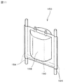
- Patent Document 2 as a battery provided with a support member, as shown in FIG. 11, in order to improve the fixing strength of the laminated case battery 150 with respect to the unit case and to improve the shape maintenance strength of the individual battery 148.
- a battery (unit battery) having a structure in which a reinforcing core member 160 is disposed between a pair of core members 154 has been proposed.
- the present invention solves the above-mentioned problems, for example, a battery including a support member that functions as a fixing part or a gripping part when a cell is assembled by combining a plurality of batteries (unit batteries). It is an object of the present invention to provide a highly reliable battery in which the support member does not cause a decrease in battery characteristics and has high fixing strength and shape maintenance strength.
- a battery element including a laminate in which a positive electrode member and a negative electrode member are opposed to each other with a separator therebetween and an electrolyte includes an outer protective layer made of resin, an intermediate gas barrier layer made of metal, and a resin.
- At least the fixing portion is configured to protrude outside from a projection range of the exterior body when viewed in a plan view.
- the main body holding portion of the support member is bonded to a peripheral portion of the exterior body by the adhesive layer of the laminate sheet constituting the exterior body.
- the exterior body is composed of a pair of laminate sheets, and among the pair of laminate sheets, one side laminate sheet is formed larger than the other side laminate sheet, Fold out the protruding part of the one-side laminate sheet that protrudes from the opposing area when both are opposed to each other, so that the adhesive layer side is inside the folded part, and the adhesive layer of the folded part is It is preferable that the supporting member is held and fixed to the exterior body by bonding to the main body holding portion.
- the main body holding portion of the support member is It is preferable that the laminated sheet is bonded to the peripheral edge of the outer package by an adhesive layer of the folded laminate sheet.
- the support member is made of a resin material or a metal material.
- the assembled battery of the present invention comprises a plurality of the batteries of the present invention as in claim 7, wherein the fixing parts of the support members of the plurality of batteries are connected, and the plurality of batteries are integrated. It is said.
- the battery of the present invention (Claim 1) includes a support member having a fixing part for fixing the battery to another member and a main body holding part, and the main body holding part of the support member is an exterior body.
- the region In the peripheral portion of the region where the battery element is accommodated, the region is held and fixed in contact with the protective layer of the laminate sheet constituting the exterior body, so that the thickness direction of the region is The movement to can be restricted. Accordingly, when an external stress such as vibration is applied, the positive electrode lead terminal and the negative electrode lead terminal are applied to a joint portion of the current collector (current collector foil) that connects the positive electrode member and the negative electrode member constituting the battery element. The load can be suppressed. In addition, it is possible to obtain a highly reliable battery that can ensure a large fixing strength and a shape maintaining strength by the support member.
- the battery may be replaced by using the fixing portion protruding from the projection range of the exterior body.
- the battery element can be easily and reliably fixed to the other member, and the battery element can be fixed to the other member in a stable state, so that the present invention can be more effectively realized.
- the exterior body is composed of a pair of laminate sheets, the one side laminate sheet is formed larger than the other side laminate sheet, and the protruding portion of the one side laminate sheet when both are opposed to each other
- the adhesive layer side is folded back to the inside of the folded portion, and the folded portion of the adhesive layer is adhered to the main body holding portion of the support member. It is possible to obtain a highly reliable battery in which the supporting member is held and fixed to the exterior body while suppressing an increase in size. Also, the planar shape and planar area of the exterior body formed by the one side laminate sheet and the other side laminate sheet are reduced to the same size as the shape and planar area of the exterior body formed when there is no protruding portion. This makes it possible to make the present invention more effective. *
- the main body holding portion of the support member is arranged as described above on the side where the positive electrode lead terminal and the negative electrode lead terminal are not drawn out. Adhering by the adhesive layer of the folded laminate sheet, while ensuring the sealing reliability of the exterior body, the main body holding part of the support member has a structure that is held and fixed on the peripheral edge of the exterior body, A highly reliable battery can be obtained.
- the support member is securely held and fixed to the exterior body, and the support member
- the assembled battery of this invention (Claim 7) connects the fixing
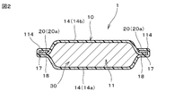
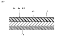
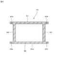
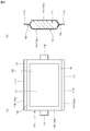
- FIG. 1 It is a top view which shows the battery concerning one Example (Example 1) of this invention. It is side surface sectional drawing of the battery concerning Example 1 of this invention. It is a figure which shows the structure of the laminate sheet which comprises the exterior body of the battery concerning Example 1 of this invention. It is a top view which shows the structure of the supporting member used in the battery concerning Example 1 of this invention. It is a figure which shows 1 process of the manufacturing method of the battery concerning Example 1 of this invention, (a) is a top view which shows the state which sealed the battery element in the exterior body, (b) is side sectional drawing.
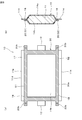
- FIG. 1 is a plan view showing a battery (lithium ion secondary battery) (unit battery) according to an embodiment of the present invention
- FIG. 2 is a side cross-sectional view showing a main part in cross section.
- a battery (lithium ion secondary battery) (unit battery) 1 of this embodiment includes a battery element 11 including a laminate formed by laminating a positive electrode member and a negative electrode member so as to face each other via a separator, and an electrolytic solution.
- the positive electrode lead terminal 12 and the negative electrode lead terminal 13 are drawn out from two opposite sides of the outer package 10 to the outside.
- the outer package 10 includes an outer protective layer 15 made of a resin (polyamide resin in this embodiment), an intermediate gas barrier layer 16 made of metal (aluminum in this embodiment), a resin ( In this embodiment, it is formed by using a pair of laminate sheets 14 (14a, 14b) which are laminated and integrated with an inner adhesive layer 17 made of polypropylene resin. That is, the exterior body 10 is arranged such that a pair of laminate sheets 14 (14a, 14b) are disposed so that the adhesive layers 17 face each other, and then the peripheral portions of the pair of laminate sheets 14 (14a, 14b) are thermally welded. It is formed by doing.
- the laminate sheet 14 (14a, 14b)
- a sheet subjected to a drawing process is used to form the accommodation space 30 (FIG. 2) for accommodating the battery element 11.
- the thickness of the battery element is thin, it is also possible to use a laminate sheet in which the recess is not drawn.
- the adhesive strength of the peripheral edge portion (heat-welded portion) 18 where the adhesive layers 17 of the laminate sheet 14 (14a, 14b) are heat-welded is strong, and is long-term under high temperature and high humidity (for example, 60 ° C. 90% RH, 3000 hours). Even if it is left as it is, the adhesive strength does not decrease, so that high bonding reliability can be obtained.
- the laminate sheet 14 (14a, 14b) is not limited to the one having the above configuration, and the adhesive layer 17 may be, for example, a mixed material of polypropylene and polyethylene.
- this battery 1 is provided with the supporting member 20 which functions as a fixing
- the support member 20 has a main body holding portion 20a having a frame-like structure and a fixing portion 20b for fixing the battery 1 to another member.
- the inner peripheral portion of the main body holding portion 20 a is a laminate sheet 14 (14 b) that constitutes the outer package 10 in the peripheral portion of the region A of the outer package 10 in which the battery element 11 is accommodated. In this state, the region A is held and fixed by the support member 20.
- the main body holding portion 20a of the support member 20 has a rectangular frame-like structure having a total of four sides, two sides S1 and S2 facing each other and sides S3 and S4 facing each other. is doing.
- the main body holding portion 20a has a frame-like structure having four sides.
- the shape is not limited to this, and various shapes such as a circular shape, a U-shape, a combination of an L shape and a rod shape can be used. Is available.
- the main body holding part can limit the movement of the region in which the battery element is accommodated in contact with the surface of the exterior body (laminate sheet) of the region in which the battery element is accommodated.
- the inner periphery is in contact with the surface of the exterior body (the laminate sheet constituting the region A (FIG. 1) in which the battery element 11 is accommodated). Since the fixing strength and the shape maintaining strength are the highest, it is preferable to have such a shape.
- the fixing portion 20b is configured to protrude outside from the projection range of the exterior body 10 when viewed in plan so that the fixing work or the like can be easily performed.
- the support member 20 folds the protruding portion 114 of the one side laminate sheet 14a formed larger than the other side laminate sheet 14b from the region facing the other side laminate sheet 14b,
- the adhesive layer 17 (FIG. 3) to a pair of opposing sides S1 and S2 constituting the main body holding portion 20a, the adhesive layer 17 is held and fixed to the peripheral edge portion (thermal welding portion) 18 of the exterior body 10. Yes.
- the support member 20 has the inner periphery of the sides S1 to S4 in contact with the exterior body of the region A in which the battery element 11 is accommodated to hold and fix the region A, thereby restricting the movement of the battery element. And the function which maintains the shape of a battery element is fulfilled.
- the opposing sides S1 and S2 constituting the main body holding portion 20a are firmly bonded and held by the adhesive layer 17 of the one side laminate sheet 14a, and the sides S1 and S2
- the fixing portions 20b on both ends have a structure that protrudes from the exterior body 10 to the outside.
- the support member 20 since a support member made of polypropylene resin is used as the support member 20, the laminate sheet 14 is firmly adhered to the adhesive layer 17 (FIG. 3) made of polypropylene resin and securely attached to the exterior body. Retained.
- the support member 20 is not limited to one made of polypropylene resin, but is made of other resin such as polyethylene, a metal such as aluminum, or a composite material of resin and metal, etc. Various materials provided with rigidity, mechanical strength, and the like can be used.
- the support member is preferably selected in consideration of the material constituting the adhesive layer of the laminate sheet, the required rigidity, mechanical strength, and the like.
- a laminate formed by laminating a positive electrode member and a negative electrode member so as to face each other through a separator, and an electrolytic solution are prepared.
- a laminate sheet 14 (14a, 14b) for forming the outer package 10 that houses the battery element 11 including the laminate and the electrolytic solution is prepared.
- a support member 20 having a frame-like structure as shown in FIG. 4 and including a main body holding portion 20a and a fixing portion 20b protruding from a corner portion of the main body holding portion 20a is prepared.
- the battery element 11 is sealed in the interior space of the exterior body 10 by injecting an appropriate amount of electrolyte into the interior of the body 10 and sealing the exterior body 10 by completely welding the periphery of the exterior body 10 while vacuuming. Obtain a stopped structure. At this time, the positive electrode lead terminal 12 and the negative electrode lead terminal 13 are drawn out to the outside from a pair of side edge portions (thermal welding portions) 18 facing each other of the outer package 10.
- the support member 20 is disposed so that the opposing sides S ⁇ b> 1 and S ⁇ b> 2 constituting the main body holding portion 20 a of the support member 20 are positioned on the peripheral edge portion (thermal welding portion) 18 on the side that is on the side.
- the sides S1 and S2 constituting the main body holding portion 20a of the support member 20 have one side laminated sheet out of the pair of laminated sheets 14a and 14b constituting the exterior 14 bodies.
- the support member 20 is securely attached to the exterior body 14 without the need for a separate adhesive or the like since it is adhered by the adhesive layer 14a and is held and fixed to the peripheral edge portion (thermal welding portion) 18 of the exterior body 14. A highly reliable battery which is bonded and fixed can be obtained.
- the support member 20 can ensure a large fixing strength and shape maintenance strength, and the main body holding portion 20a of the support member 20 is in contact with the exterior body of the region A in which the battery element 11 is accommodated. Since A is held and fixed, a highly reliable battery 1 can be obtained (FIG. 1).
- the planar shape and the planar area of the exterior body 14 formed by the one-side laminated sheet 14a and the other-side laminated sheet 14b are the protruding portion.
- the shape and the planar area of the exterior body 14 formed when there is no 114 can be the same shape and the same size, and the size of the product is not increased.
- the main body holding portion 20a of the support member 20 is bonded and fixed by the adhesive layer 17 of the folded laminate sheet 14a.
- a highly reliable battery having a structure bonded to (part) 18 can be obtained.
- the support member 20 is made of the same polyethylene resin as the material constituting the adhesive layer 17 of the laminate sheet 14, the support member 20 is securely bonded and fixed to the exterior body 14. In addition, it is possible to obtain a highly reliable battery 1 in which the strength of the support member 20 is large.
- the battery having a structure in which the positive electrode lead terminal and the negative electrode lead terminal are drawn from opposite sides of the rectangular outer casing is described as an example.
- the present invention can also be applied to the battery 1 having a configuration in which the positive electrode lead terminal 12 and the negative electrode lead terminal 13 are drawn from one side of the outer package 14.
- the one side laminate sheet 14a is formed on the pair of sides of the outer package 14 perpendicular to the sides from which the positive electrode lead terminal 12 and the negative electrode lead terminal 13 are drawn.
- the protruding portion 114 is formed, the protruding portion 114 is folded back, and the adhesive layer of the folded portion is bonded to the pair of opposing sides S1 and S2 constituting the main body holding portion 20a of the support member 20.
- the positive electrode lead terminal 12 and the negative electrode lead terminal 13 are pulled out from one side of the outer package 14, and the positive electrode lead terminal 12 and the negative electrode lead terminal 13 are perpendicular to the side from which the positive electrode lead terminal 12 and the negative electrode lead terminal 13 are pulled out.
- the battery 1 having a structure in which the pair of opposing sides S1 and S2 of the main body holding portion 20a is held and fixed to the peripheral edge portion (thermal welding portion) 18 of the exterior body 14 is obtained.
- a protruding portion 114 is formed in the one-side laminate sheet 14a, the protruding portion 114 is folded back, and the adhesive layer of the folded portion is used as a support member. It adheres to sides S1, S2 and S3 constituting 20 main body holding portions 20a.
- the positive electrode lead terminal 12 and the negative electrode lead terminal 13 are pulled out from one side of the outer package 14, and the positive electrode lead terminal 12 and the negative electrode lead terminal 13 are perpendicular to the side from which the positive electrode lead terminal 12 and the negative electrode lead terminal 13 are pulled out.
- Three sides S1, S2, and S3 constituting the main body holding portion 20a on one side and one side that faces the side from which the positive electrode lead terminal 12 and the negative electrode lead terminal 13 are drawn out are the peripheral edges of the exterior body 14.
- the battery 1 having a structure held and fixed to the part (thermal welding part) 18 can be obtained.
- the supporting member is smaller than the total thickness of the battery element and the outer package (that is, the thickness of the battery) is used as an example of the supporting member.
- the outer package that is, the thickness of the battery
- the present invention is not limited to the above-described embodiment, and the specific shape and constituent material of the support member, the specific configuration of the laminate sheet constituting the exterior body, and the constituent material of the battery element Various applications and modifications can be made within the scope of the invention with respect to types and the like.
- the stacked body in which the positive electrode member and the negative electrode member are stacked so as to face each other via the separator may be a single wafer type or a wound type.
- the laminate sheet is not limited to a structure in which the adhesive layers are opposed to each other by a pair of laminate sheets, and may be configured to have a structure in which one laminate sheet is bent and the adhesive layer on the inner surface side is opposed.
Landscapes
- Chemical & Material Sciences (AREA)
- Chemical Kinetics & Catalysis (AREA)
- Electrochemistry (AREA)
- General Chemical & Material Sciences (AREA)
- Inorganic Chemistry (AREA)
- Sealing Battery Cases Or Jackets (AREA)
- Battery Mounting, Suspending (AREA)
- Connection Of Batteries Or Terminals (AREA)
Abstract
Description
正極部材と負極部材とがセパレータを介して互いに対向するように積層された積層体と電解質とを含む電池要素が、樹脂からなる外側の保護層と、金属からなる中間のガスバリア層と、樹脂からなる内側の接着層とを積層して一体化したラミネートシートを、前記接着層どうしが互いに対向するように配設して熱溶着することにより形成された外装体の内部に収容され、かつ、前記正極部材と導通する正極リード端子と、前記負極部材と導通する負極リード端子とが、前記外装体の外部に引き出された構造を有する電池であって、
当該電池を他の部材に固定するための固定部と、前記外装体の前記電池要素が収容された領域を保持、固定する本体保持部とを有する支持部材を備えているとともに、
前記本体保持部が、前記外装体の前記領域の周縁部において、前記外装体を構成する前記ラミネートシートの前記保護層に接した状態で、前記領域が保持、固定されていること
を特徴としている。
また、上記固定部20bは、固定作業などを容易に行うことができるように、平面視した場合における外装体10の投影範囲から外部に突出するように構成されている。
このとき、正極リード端子12および負極リード端子13が外装体10の互いに対向する一対の辺側の周縁部(熱溶着部)18から外部に引き出されるようにする。
10 外装体
11 電池要素
12 正極リード端子
13 負極リード端子
14(14a,14b) ラミネートシート
15 外側の保護層(ポリアミド樹脂層)
16 ガスバリア層(アルミニウム層)
17 内側の接着層(ポリプロピレン樹脂層)
18 周縁部(熱溶着部)
20 支持部材
20a 支持部材の本体保持部
20b 支持部材の固定部
30 収容空間
114 はみ出し部
A 電池要素の収容された領域
S1,S2,S3,S4 支持部材の本体保持部の各辺
Claims (7)
- 正極部材と負極部材とがセパレータを介して互いに対向するように積層された積層体と電解質とを含む電池要素が、樹脂からなる外側の保護層と、金属からなる中間のガスバリア層と、樹脂からなる内側の接着層とを積層して一体化したラミネートシートを、前記接着層どうしが互いに対向するように配設して熱溶着することにより形成された外装体の内部に収容され、かつ、前記正極部材と導通する正極リード端子と、前記負極部材と導通する負極リード端子とが、前記外装体の外部に引き出された構造を有する電池であって、
当該電池を他の部材に固定するための固定部と、前記外装体の前記電池要素が収容された領域を保持、固定する本体保持部とを有する支持部材を備えているとともに、
前記本体保持部が、前記外装体の前記領域の周縁部において、前記外装体を構成する前記ラミネートシートの前記保護層に接した状態で、前記領域が保持、固定されていること
を特徴とする電池。 - 少なくとも前記固定部が、平面視した場合における前記外装体の投影範囲から外部に突出するように構成されていることを特徴とする請求項1記載の電池。
- 前記支持部材の前記本体保持部が、前記外装体を構成する前記ラミネートシートの前記接着層により前記外装体の周縁部に接着されていることを特徴とする請求項1または2記載の電池。
- 前記外装体が一対のラミネートシートからなり、前記一対のラミネートシートのうち、一方側ラミネートシートを他方側ラミネートシートよりも大きく形成し、両者を対向させたときに両者の対向領域からはみ出す前記一方側ラミネートシートのはみ出し部分を、前記接着層側が折り返し部分の内側となるように折り返し、該折り返した部分の前記接着層を前記支持部材の前記本体保持部に接着させることにより、前記支持部材が前記外装体に保持、固定されていることを特徴とする請求項1~3のいずれかに記載の電池。
- 前記外装体の平面形状が方形であって、前記正極リード端子と、前記負極リード端子とが引き出されていない辺において、前記支持部材の本体保持部が、前記折り返されたラミネートシートの接着層により、前記外装体の周縁部に接着されていることを特徴とする請求項4記載の電池。
- 前記支持部材が樹脂材料または金属材料から形成されたものであることを特徴とする請求項1~5のいずれかに記載の電池。
- 前記請求項1~6のいずれかに記載の電池を複数備え、複数の電池のそれぞれの支持部材の固定部を連結し、前記複数の電池を一体化したことを特徴とする組電池。
Priority Applications (3)
| Application Number | Priority Date | Filing Date | Title |
|---|---|---|---|
| DE112012002605.5T DE112012002605T5 (de) | 2011-06-21 | 2012-06-15 | Batterie |
| JP2013521564A JP5741688B2 (ja) | 2011-06-21 | 2012-06-15 | 電池 |
| US14/134,507 US9595698B2 (en) | 2011-06-21 | 2013-12-19 | Battery |
Applications Claiming Priority (2)
| Application Number | Priority Date | Filing Date | Title |
|---|---|---|---|
| JP2011-137124 | 2011-06-21 | ||
| JP2011137124 | 2011-06-21 |
Related Child Applications (1)
| Application Number | Title | Priority Date | Filing Date |
|---|---|---|---|
| US14/134,507 Continuation US9595698B2 (en) | 2011-06-21 | 2013-12-19 | Battery |
Publications (1)
| Publication Number | Publication Date |
|---|---|
| WO2012176711A1 true WO2012176711A1 (ja) | 2012-12-27 |
Family
ID=47422549
Family Applications (1)
| Application Number | Title | Priority Date | Filing Date |
|---|---|---|---|
| PCT/JP2012/065380 Ceased WO2012176711A1 (ja) | 2011-06-21 | 2012-06-15 | 電池 |
Country Status (4)
| Country | Link |
|---|---|
| US (1) | US9595698B2 (ja) |
| JP (1) | JP5741688B2 (ja) |
| DE (1) | DE112012002605T5 (ja) |
| WO (1) | WO2012176711A1 (ja) |
Cited By (4)
| Publication number | Priority date | Publication date | Assignee | Title |
|---|---|---|---|---|
| JP2014032789A (ja) * | 2012-08-02 | 2014-02-20 | Nissan Motor Co Ltd | 薄型電池 |
| WO2014087836A1 (ja) * | 2012-12-06 | 2014-06-12 | 株式会社村田製作所 | 電池およびそれを用いた組電池 |
| JP2016001574A (ja) * | 2014-06-12 | 2016-01-07 | 株式会社デンソー | ラミネート外装電池 |
| JPWO2014087837A1 (ja) * | 2012-12-06 | 2017-01-05 | 株式会社村田製作所 | 電池およびそれを用いた組電池 |
Families Citing this family (2)
| Publication number | Priority date | Publication date | Assignee | Title |
|---|---|---|---|---|
| KR102513784B1 (ko) * | 2015-10-07 | 2023-03-23 | 에스케이온 주식회사 | 리튬 이차 전지 |
| DE102016206003B4 (de) | 2016-04-11 | 2022-06-02 | Volkswagen Aktiengesellschaft | Schwingungsdämpfer |
Citations (4)
| Publication number | Priority date | Publication date | Assignee | Title |
|---|---|---|---|---|
| JP2004006226A (ja) * | 2002-04-17 | 2004-01-08 | Hitachi Maxell Ltd | 電池 |
| JP2005268029A (ja) * | 2004-03-18 | 2005-09-29 | Nissan Motor Co Ltd | 導電部材および組電池 |
| JP2005302501A (ja) * | 2004-04-12 | 2005-10-27 | Uchiyama Mfg Corp | バッテリーセル用ケース |
| JP2008103239A (ja) * | 2006-09-20 | 2008-05-01 | Dainippon Printing Co Ltd | 扁平型電気化学セル及びそれを組み合わせてなる組電池 |
Family Cites Families (9)
| Publication number | Priority date | Publication date | Assignee | Title |
|---|---|---|---|---|
| JP2003068257A (ja) | 2001-08-29 | 2003-03-07 | Toyota Motor Corp | ラミネートケース電池 |
| KR20040048295A (ko) | 2002-12-02 | 2004-06-07 | 히다치 막셀 가부시키가이샤 | 전지 |
| KR100880386B1 (ko) * | 2005-06-03 | 2009-01-23 | 주식회사 엘지화학 | 신규한 구조의 이차전지 및 이를 포함하는 전지팩 |
| JP4625733B2 (ja) * | 2005-07-26 | 2011-02-02 | 株式会社東芝 | 非水電解質二次電池及び電池パック |
| KR100908569B1 (ko) * | 2005-11-02 | 2009-07-22 | 주식회사 엘지화학 | 전지모듈의 제조방법 |
| JP5470751B2 (ja) * | 2008-02-13 | 2014-04-16 | Tdk株式会社 | 活物質及び電極の製造方法、活物質及び電極 |
| JP5374979B2 (ja) | 2008-09-10 | 2013-12-25 | 株式会社村田製作所 | 電池と組電池 |
| KR101089086B1 (ko) * | 2008-10-30 | 2011-12-06 | 주식회사 엘지화학 | 전지 카트리지와 이를 포함하는 전지모듈 |
| US8852789B2 (en) * | 2010-11-04 | 2014-10-07 | Samsung Sdi Co., Ltd. | Battery module having battery cell holder |
-
2012
- 2012-06-15 JP JP2013521564A patent/JP5741688B2/ja not_active Expired - Fee Related
- 2012-06-15 DE DE112012002605.5T patent/DE112012002605T5/de not_active Withdrawn
- 2012-06-15 WO PCT/JP2012/065380 patent/WO2012176711A1/ja not_active Ceased
-
2013
- 2013-12-19 US US14/134,507 patent/US9595698B2/en active Active
Patent Citations (4)
| Publication number | Priority date | Publication date | Assignee | Title |
|---|---|---|---|---|
| JP2004006226A (ja) * | 2002-04-17 | 2004-01-08 | Hitachi Maxell Ltd | 電池 |
| JP2005268029A (ja) * | 2004-03-18 | 2005-09-29 | Nissan Motor Co Ltd | 導電部材および組電池 |
| JP2005302501A (ja) * | 2004-04-12 | 2005-10-27 | Uchiyama Mfg Corp | バッテリーセル用ケース |
| JP2008103239A (ja) * | 2006-09-20 | 2008-05-01 | Dainippon Printing Co Ltd | 扁平型電気化学セル及びそれを組み合わせてなる組電池 |
Cited By (4)
| Publication number | Priority date | Publication date | Assignee | Title |
|---|---|---|---|---|
| JP2014032789A (ja) * | 2012-08-02 | 2014-02-20 | Nissan Motor Co Ltd | 薄型電池 |
| WO2014087836A1 (ja) * | 2012-12-06 | 2014-06-12 | 株式会社村田製作所 | 電池およびそれを用いた組電池 |
| JPWO2014087837A1 (ja) * | 2012-12-06 | 2017-01-05 | 株式会社村田製作所 | 電池およびそれを用いた組電池 |
| JP2016001574A (ja) * | 2014-06-12 | 2016-01-07 | 株式会社デンソー | ラミネート外装電池 |
Also Published As
| Publication number | Publication date |
|---|---|
| US20140106201A1 (en) | 2014-04-17 |
| JPWO2012176711A1 (ja) | 2015-02-23 |
| DE112012002605T5 (de) | 2014-04-03 |
| US9595698B2 (en) | 2017-03-14 |
| JP5741688B2 (ja) | 2015-07-01 |
Similar Documents
| Publication | Publication Date | Title |
|---|---|---|
| KR101348366B1 (ko) | 비대칭 구조의 전지셀 및 이를 포함하는 전지팩 | |
| US10727527B2 (en) | Electrode assembly | |
| KR100870354B1 (ko) | 전지외장재 및 그를 이용한 이차전지 | |
| KR101216422B1 (ko) | 실링부의 절연성이 향상된 이차전지 | |
| JP6743664B2 (ja) | 蓄電装置及び蓄電装置の製造方法 | |
| JP5741688B2 (ja) | 電池 | |
| JP2015520932A (ja) | 単一電極端子結合部を有する電池組合体 | |
| JP6273665B2 (ja) | 電気化学デバイス | |
| JP6045987B2 (ja) | 角形二次電池 | |
| KR20170029283A (ko) | 배터리 모듈 | |
| CN108604710A (zh) | 层叠型非水电解质二次电池 | |
| CN116547773A (zh) | 蓄电装置 | |
| JP7479199B2 (ja) | 電池セル | |
| US20120064385A1 (en) | Secondary battery and manufacturing method thereof | |
| US20220278395A1 (en) | Pouch cell | |
| KR20180006364A (ko) | 전지셀 어셈블리 | |
| US20140293511A1 (en) | Electric storage device | |
| JP7695638B2 (ja) | 電極体、及び蓄電素子 | |
| JP4932484B2 (ja) | 収納部材、収納ケースおよび組電池 | |
| KR20080010738A (ko) | 중첩식 이차전지 | |
| JP6089832B2 (ja) | 蓄電素子 | |
| JP6155724B2 (ja) | 蓄電素子及び蓄電素子の製造方法 | |
| JP5741692B2 (ja) | 電池 | |
| JP7479197B2 (ja) | 電池セル | |
| JP2005079081A (ja) | 薄型パック電池 |
Legal Events
| Date | Code | Title | Description |
|---|---|---|---|
| 121 | Ep: the epo has been informed by wipo that ep was designated in this application |
Ref document number: 12802200 Country of ref document: EP Kind code of ref document: A1 |
|
| ENP | Entry into the national phase |
Ref document number: 2013521564 Country of ref document: JP Kind code of ref document: A |
|
| WWE | Wipo information: entry into national phase |
Ref document number: 1120120026055 Country of ref document: DE Ref document number: 112012002605 Country of ref document: DE |
|
| 122 | Ep: pct application non-entry in european phase |
Ref document number: 12802200 Country of ref document: EP Kind code of ref document: A1 |