WO2012173246A1 - 蓋開閉機構及び収納装置 - Google Patents
蓋開閉機構及び収納装置 Download PDFInfo
- Publication number
- WO2012173246A1 WO2012173246A1 PCT/JP2012/065413 JP2012065413W WO2012173246A1 WO 2012173246 A1 WO2012173246 A1 WO 2012173246A1 JP 2012065413 W JP2012065413 W JP 2012065413W WO 2012173246 A1 WO2012173246 A1 WO 2012173246A1
- Authority
- WO
- WIPO (PCT)
- Prior art keywords
- lid
- opening
- arm
- closing mechanism
- base body
- Prior art date
- Legal status (The legal status is an assumption and is not a legal conclusion. Google has not performed a legal analysis and makes no representation as to the accuracy of the status listed.)
- Ceased
Links
Images




Classifications
-
- B—PERFORMING OPERATIONS; TRANSPORTING
- B65—CONVEYING; PACKING; STORING; HANDLING THIN OR FILAMENTARY MATERIAL
- B65D—CONTAINERS FOR STORAGE OR TRANSPORT OF ARTICLES OR MATERIALS, e.g. BAGS, BARRELS, BOTTLES, BOXES, CANS, CARTONS, CRATES, DRUMS, JARS, TANKS, HOPPERS, FORWARDING CONTAINERS; ACCESSORIES, CLOSURES, OR FITTINGS THEREFOR; PACKAGING ELEMENTS; PACKAGES
- B65D51/00—Closures not otherwise provided for
- B65D51/24—Closures not otherwise provided for combined or co-operating with auxiliary devices for non-closing purposes
- B65D51/243—Closures not otherwise provided for combined or co-operating with auxiliary devices for non-closing purposes combined with an opening device
-
- B—PERFORMING OPERATIONS; TRANSPORTING
- B60—VEHICLES IN GENERAL
- B60R—VEHICLES, VEHICLE FITTINGS, OR VEHICLE PARTS, NOT OTHERWISE PROVIDED FOR
- B60R7/00—Stowing or holding appliances inside vehicle primarily intended for personal property smaller than suit-cases, e.g. travelling articles, or maps
- B60R7/04—Stowing or holding appliances inside vehicle primarily intended for personal property smaller than suit-cases, e.g. travelling articles, or maps in driver or passenger space, e.g. using racks
- B60R7/06—Stowing or holding appliances inside vehicle primarily intended for personal property smaller than suit-cases, e.g. travelling articles, or maps in driver or passenger space, e.g. using racks mounted on or below dashboards
-
- E—FIXED CONSTRUCTIONS
- E05—LOCKS; KEYS; WINDOW OR DOOR FITTINGS; SAFES
- E05F—DEVICES FOR MOVING WINGS INTO OPEN OR CLOSED POSITION; CHECKS FOR WINGS; WING FITTINGS NOT OTHERWISE PROVIDED FOR, CONCERNED WITH THE FUNCTIONING OF THE WING
- E05F1/00—Closers or openers for wings, not otherwise provided for in this subclass
- E05F1/08—Closers or openers for wings, not otherwise provided for in this subclass spring-actuated, e.g. for horizontally sliding wings
- E05F1/10—Closers or openers for wings, not otherwise provided for in this subclass spring-actuated, e.g. for horizontally sliding wings for swinging wings, e.g. counterbalance
-
- E—FIXED CONSTRUCTIONS
- E05—LOCKS; KEYS; WINDOW OR DOOR FITTINGS; SAFES
- E05Y—INDEXING SCHEME ASSOCIATED WITH SUBCLASSES E05D AND E05F, RELATING TO CONSTRUCTION ELEMENTS, ELECTRIC CONTROL, POWER SUPPLY, POWER SIGNAL OR TRANSMISSION, USER INTERFACES, MOUNTING OR COUPLING, DETAILS, ACCESSORIES, AUXILIARY OPERATIONS NOT OTHERWISE PROVIDED FOR, APPLICATION THEREOF
- E05Y2900/00—Application of doors, windows, wings or fittings thereof
- E05Y2900/50—Application of doors, windows, wings or fittings thereof for vehicles
- E05Y2900/53—Type of wing
- E05Y2900/538—Interior lids
Definitions
- the present invention relates to a lid opening / closing mechanism and a storage device for switching a lid (including a door, a cover, a shielding plate, and the like) between a closed position and an open position for closing a base-side opening.
- a storage device provided in a passenger compartment is often restricted by the opening / closing locus of the lid due to the panel shape in the vicinity of the arrangement section and the relationship with other members and articles, and the lid is rotated as close as possible to the base. It is required to move or rotate while suppressing the amount of protrusion of the lid from the base as much as possible.
- countermeasures include Patent Documents 1 and 2 previously developed by the present applicant.
- Reference numeral 2 denotes a base
- reference numeral 3 denotes a lid (door).
- the lid 3 has a support arm 32, a gear part 32a provided on the arm 32, and a sliding part (not shown) provided at the approximate center of the arc of the gear part 32a.
- the base body 2 includes a first rack portion 11 that meshes with a gear portion 32a provided substantially parallel to each other, a guide groove 13 that meshes with the sliding portion, and the like.
- the lid 3 is opened and closed by meshing the gear portion 32a with the first rack portion 11 (meshing a gear (not shown) with the second rack portion 12) and meshing with the sliding portion with respect to the guide groove 13. Due to the accompanying movement, a trajectory accompanied by rotation and movement of the lid 3 is obtained. Further, in this mechanism, the slider 4 that is slidably assembled to the base 2 and connected to the lid 3, the biasing means 5 that biases the slider 4, and the lid 3 are locked in the closed position. The lid 3 is switched from the open position to the closed position against the urging force of the urging means 5 and is locked at the closed position by the detachment mechanism section.
- 10 (a) and 10 (b) show the mechanism of Patent Document 2, wherein (a) shows the closed position of the lid and (b) shows the opened position of the lid.
- Reference sign S or Sa is a base (main body), and reference sign M or Ma is a lid (lid).
- the base arm 1 is assembled to the lid M with the first pivot A
- the base arm 1 is assembled to the stationary body S with the second pivot B
- the third pivot C is assembled to the lid M
- the stationary body A control arm 2 having a sliding portion 2b guided by a cam portion 4 provided in S and a support body 3 rotatably attached to a fixed body S with a fourth pivot support portion D are provided.
- the control arm 2 is assembled so as to be movable with respect to the support 3.
- the cam part 4 has a first part 4a and a second part 4e following the first part 4a.
- the third pivot part C and the second part 4e are provided.
- the lid M is rotated around the first pivot A while changing the distance of the four pivots D.
- the opening and closing of the lid M is moved to the predetermined forward movement position by an operation using a four-bar link, and after reaching the predetermined forward movement position, a rotational movement about one axis is performed.
- the first urging means 5 for applying the turning force around the second pivot B to the base arm 1 and the engagement / disengagement mechanism unit (not shown) for locking the lid 3 in the closed position.
- the lid 3 is switched from the open position to the closed position against the urging force of the first urging means 5 and is closed by the engagement / disengagement mechanism section. It is locked to.
- the lid can be rotated while approaching the base as much as possible as compared with the configuration in which the lid is rotated about the pivotal support portion whose position is fixed, and the protruding amount of the lid from the base can be suppressed.
- the lid in each mechanism, for example, in the case of Patent Document 1, it is difficult to reduce the manufacturing cost because processing accuracy is required because the engagement of the rack part and the gear part is essential.
- a large space is required on the base side for providing a space for disposing the control arm and a cam portion for controlling the movement of the control arm.
- the present invention has been developed from the above background.
- the purpose of the lid opening / closing mechanism and the storage device is to simplify the configuration and to increase the degree of freedom in designing the lid opening / closing locus while suppressing the space required on the substrate side, and to make it easy to improve the opening / closing operability.
- a lid opening / closing mechanism includes a lid opening / closing mechanism that switches a lid between a closed position that closes an opening of a box-shaped substrate and an open position that opens the opening.
- a base end side pivotally supported by a support portion, with a distal end side pivotable to the front of the base body, and an arm that is pivotally connected to the lid by a second shaft support portion; It is characterized by being rotated in the opening direction or the closing direction in conjunction with the rotation of the arm.
- the lid opening / closing mechanism is more preferably embodied as described below. That is, (1) A control member that is slidably disposed on a guide portion provided on the base body and is rotatably connected to the lid via a third shaft support portion on the lid side, In the opening and closing process of the lid, the second shaft support portion moves to the front of the base body by the rotation of the arm around the first shaft support portion, and the first shaft support portion, the second shaft support portion, and the third shaft support portion.
- the lids are reversed and switched in the opening direction or the closing direction with a relatively straight line as a boundary. Note that “the lid can be reversed and switched in the opening direction or the closing direction” means that the lid is, for example, as shown in FIGS.
- the first shaft support portion 9a (12c) and the second shaft support portion 9b ( 26a) and the third shaft support portion 42 (24a) are switched from the state where they are relatively aligned substantially in a straight line to the closing direction as shown in FIGS. 6 (a) to 6 (c), or FIG. It means that it can be switched to the opening direction as shown in c).
- the arm and the control member do not need to be directly connected or arranged in parallel as in Patent Documents 1 and 2, the arm and the control member can be arranged at different locations of the base body as in the form. From this point, the degree of freedom in design can be expanded.
- the lid is switched from the state in which the first shaft support portion, the second shaft support portion, and the third shaft support portion are relatively aligned in a straight line (hereinafter referred to as a lid switching position) to the closing direction.
- a lid switching position a straight line
- the biasing means for biasing the control member as in this preferred mode is provided, it is possible to switch from the halfway switching state of the lid to the closed position and the open position by the biasing force.
- An engagement / disengagement mechanism for locking the lid in the closed position as in the patent document is also unnecessary.
- the control member reduces the amount of protrusion to the front of the base when the lid is in the closed position or the open position, and is rotated from the closed position to the open direction or from the open position to the close direction.
- the amount of protrusion to the front of the base is maximized.
- the operation characteristics of the control member are clarified.
- the control member reduces the amount of protrusion to the front of the base body at the closed position or the open position of the cover, and moves to the front of the base body at the position where the cover is being switched.
- the amount of protrusion is maximized. This point is suitable when, for example, the lid reversal system as in this preferred mode can be switched from the midway position of the lid to the closed position and the open position by the urging force.
- the control member accumulates an urging force in the process of increasing the amount of protrusion toward the front of the base and makes the control member movable by the urging force in the process of reducing the amount of protrusion toward the front of the base.
- It is the structure which has a biasing means.
- the lid is rotated from the open position or the closed position to the switching intermediate position against the urging force of the urging means (accumulating the urging force), and the lid is opened and closed from the switching intermediate position. The position can be turned by the urging force of the urging means, thereby improving the usability.
- a structure having a braking means for braking the sliding of the control member since the control member is slid slowly by the braking means, the opening / closing speed of the lid can be relaxed via the control member, thereby providing a high-class feeling.
- the arm is urged by the urging means at the open position of the lid, inadvertent swinging of the arm is prevented particularly at the open position of the lid, thereby keeping the lid in a stable state. Try to sag.
- a structure having a braking means for braking the rotation of the arm since the arm is slowly rotated by the braking means, the opening / closing speed of the lid via the arm can be relaxed, thereby giving a high-class feeling.
- the arm is disposed on at least one side of both sides of the base body at the closed position of the lid, and the control member is disposed on one of the upper and lower surfaces of the base body. According to this preferable aspect, for example, it is easy to adopt even if the base is a flat box shape as compared with Patent Documents 1 and 2.
- the storage device specifies an application example of the lid opening / closing mechanism according to the present invention, and is provided in an embedded state with respect to a panel portion in which a box-shaped substrate stands or rises obliquely.
- the storage device in which the opening is arranged substantially horizontally or obliquely, the storage device has a lid for opening and closing the opening, and the lid is switched by the lid opening / closing mechanism according to the present invention.
- the arm is easy to eliminate the interference of the arm with respect to the base because the cover is rotated while the arm rotates about the base-side first shaft support portion toward the front of the base.
- the lid is connected to the arm pivoted about the first shaft support portion via the second shaft support portion and moved to the front of the base body, and the lid is moved to the open position with the second shaft support portion serving as a fulcrum. Switchable.
- the second shaft support portion moves forward of the base body by the rotation of the arm in the open position of the cover, compared to the conventional configuration in which the cover is rotated around the pivot support portion whose position is fixed.
- the height with respect to the substrate can be kept low in proportion to
- the storage device according to the present invention is an advantage of the lid opening / closing mechanism according to the present invention as a storage device in which the base is provided in an embedded state with respect to the panel portion standing up or obliquely and the opening is disposed substantially horizontally or diagonally. Can be provided.
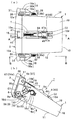
- FIGS. 3A to 3C are cross-sectional views taken along the line AA in FIG.
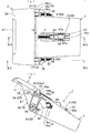
- FIGS. 4A to 4C are cross-sectional views taken along the line A2-A2 in FIG. 4A, showing the lid opening / closing mechanism of the storage device at a position during the switching of the lid, and a cross-sectional view taken along the line B2-B2 in FIG.
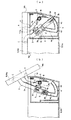
- FIGS. 5A to 5C are cross-sectional views taken along the line A3-A3 in FIG. 5A showing the lid opening / closing mechanism of the storage device in the open position of the lid, and a cross-sectional view taken along the line B3-B3 in FIG.
- FIG. (A) And (b) is explanatory drawing for demonstrating the principal part of patent document 1.
- FIG. (A) And (b) is explanatory drawing for demonstrating the principal part of patent document 2.
- FIG. (A) And (b) is explanatory drawing for demonstrating the principal part of patent document 2.
- FIG. (A) And (b) is explanatory drawing for demonstrating the principal part of patent document 2.
- each (a) is a top view as viewed from the Z direction of (b).
- the box-shaped substrate 1 has an opening on the front or front side, and the opening is opened and closed by the lid 2.
- the arrangement feature is provided in a state of being embedded in a center console or an instrument panel (for example, a recess provided at an approximately middle position in the vehicle width) in the vehicle interior.
- a center console or an instrument panel for example, a recess provided at an approximately middle position in the vehicle width
- the box-shaped substrate 1 only needs to have an opening corresponding to the lid 2 and an arrangement place such as an arm 3 and a control member 4 described later, and the inside and appearance are variously modified depending on the purpose of use.
- substrate 1 should just be provided with the requirements that it opens and closes by rotation of the lid
- the lid 2 is intended to be switched to a closed position and an open position with respect to the opening of the base body 1 by rotation.
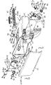
- the lid opening / closing mechanism is configured to switch the lid 2 between a closed position and an open position with respect to the opening of the base body 1 by means of an arm 3, a control member 4, a biasing member 5, a coil spring 7, and the like. It is configured.
- the base body 1, the lid 2, the arm 3, and the control member 4 are all resin molded products, but other materials may be used.
- the inside of the substrate 1 is partitioned into an upper surface 10, a bottom surface 11, both side surfaces 12, and a rear surface 13, and has a container shape having an opening on the front side.
- the upper surface 10 is provided with a standing wall 14 projecting from the upper edge that defines the opening, and a cylindrical guide portion 15 connected to the middle of the inner surface.
- the guide portion 15 is a portion that guides the sliding of the control member 4 and protrudes forward by a predetermined length from the opening, and the rear side of the standing wall 14 lacks an upper portion to form a groove portion 15a having a U-shaped cross section. .
- both side walls 10a erected on the upper surface 10 In the vicinity of the groove 15a, both side walls 10a erected on the upper surface 10, a mounting part 10b projecting from the upper end surface of each side wall 10a, a rear wall 10d erected on the rear side of the groove 15a, and erected in front of the standing wall 14.
- a regulating piece 10e is provided.
- a damper 8A which will be described later, is attached to the attachment portions 10b on both sides.
- Reference numeral C2 is a cushion for cushioning which is attached to the inner end face of the rear wall 10d.
- a front projecting wall 12 a projecting forward from the upper and lower surfaces 10, 11, a support portion 16 that divides the arm placement space 17 between the front projecting wall 12 a, and the support portions 16 A damper mounting portion 18 disposed on the rear side is provided.
- a plurality of ribs 12b are provided on the front protruding wall 12a so as to improve the movement of the arm 3.
- the support portion 16 is integrated with the upper horizontal wall 16a, the upper partition wall 16b, the lower rear vertical wall 16c, the lower horizontal wall 16d, the front vertical wall 16e, the upper horizontal wall 16a, and the front vertical wall 16e, and faces the front protruding wall 12a.
- positioning space 17 comprised by the opposing wall 16g (refer FIG. 1) and opened in the front-back direction between each front protrusion wall 12a is formed.
- the damper 8 is attached to the attachment portion 18.
- the damper 8 and the above-described damper 8A are formed of a known rotary damper, and have a main body 8a, an output shaft that rotates while receiving resistance such as hydraulic oil, and a rotary gear 8b attached to the output shaft. ing.
- the damper 8 is attached to the mounting portion 18 with screws 9c.
- the above-described damper 8A is attached to each attachment portion 10b with a screw 9d.
- the lid 2 is made of a substantially rectangular plate having a size covering the opening of the base body 1 and the standing wall 14 and the support portions 16 on both sides as shown in FIGS. 1 and 2, and is shallow on the lower side of the design surface 20.
- An operation gripping portion 21 partitioned by a groove and a thick portion 23 on the upper side of the back surface and excluding the left and right intermediate portions 24 and both side portions 25 are formed.
- the intermediate portion 24 is a concave shape for escaping the front cylindrical portion of the guide portion 15 and the connecting piece portion 41 of the control member 4 slid along the guide portion 15, and has a concave opposite inner end surface as shown in FIG.
- a shaft hole 24a is formed in the shaft.
- Both side portions 25 are provided with connecting piece portions 26 to be inserted into the arrangement space 17 on the base body side.
- Each connecting piece 26 has a mounting hole 26a that can be connected to the shaft hole 37 of the arm via a screw 9b.
- Reference numeral C1 denotes a cushion for cushioning which is attached to the lower side of the side portions 25.
- the lid 2 described above is switched between a closed position for closing the opening of the substrate 1 and an open position for opening the opening by the lid opening / closing mechanism of the present invention.
- the lid opening / closing mechanism has a base end side pivotally supported by a screw 9a serving as a first shaft support portion on the base body 1 as a fulcrum, and the tip end side is rotatable forward of the base body, and the lid 2 is a screw serving as a second shaft support portion.
- 9b is slidably disposed on the base 3 side guide portion 15 and the arm 3 that is pivotably connected by the base 9b, and the distal end side connecting piece portion 41 is connected to the lid 2 as a third shaft support portion.
- the operating feature is that the screw 9 b as the second shaft support portion moves forward of the base body by the rotation of the arm 3 around the screw 9 a (shaft hole 34) as the first shaft support portion.
- the screw 9a (shaft hole 34) as the first shaft support, the screw 9b (shaft holes 37 and 26a) as the second shaft support, and the shaft 42 (shaft hole 24a) as the third shaft support are relatively nearly The purpose of this is to allow the lid 2 to be reversed and switched in the opening direction or the closing direction with the alignment in a straight line.
- this detailed configuration will be clarified.
- the arm 3 includes a right arm 3A and a left arm 3B that are symmetrical, and includes a lower base end portion 30, a connecting piece portion 31 that stands up from the base end portion 30, and a rear lower side from the base end portion 30.
- the guide portion 32 extends in an arc shape.
- the base end portion 30 forms a lower cylindrical shaft hole 34 and a plurality of upper spring locking portions 35.
- the connecting piece 31 has a shaft hole 37 formed on the tip side.
- the guide part 32 forms a tooth part 38 continuous on the outer periphery.
- the screw 9 a is engaged with the corresponding portion of the front projecting wall 12 a via the collar 6 and the shaft hole 34, thereby rotating by a predetermined angle with respect to the base 1.
- the connection piece 31 is pivotally supported so that the connection piece 31 abuts against the upper partition wall 16b, as shown in FIGS. 3A and 4B.
- the screw 9a which is the first shaft support, is rotated as a fulcrum and can be switched to a tilted state (the cover switching middle position and the open position) with the tip side shifted to the front of the base body. .
- the tooth portion 38 of the guide portion 32 is engaged with the rotary gear 8b of the damper 8 described above.
- the arm 3 is switched between the standing state and the tilting state while being slowly rotated by receiving the braking action of the damper 8.
- the lid 2 is rotated with the screw 9b as a fulcrum in a state where the screw 9b as the second shaft support portion is engaged with the shaft hole 26a from the shaft hole 37 with respect to each connecting piece portion 31 of the arms 3A and 3B. It is connected and supported movably.
- the collar 6 is composed of a head portion 6a and a cylindrical portion 6b, and has a shaft hole 6c through which a screw 9a passes.
- the head 6a prevents the torsion spring 5 supported by the cylindrical part forming the shaft hole 34 from falling off.
- the torsion spring 5 has one end 5a of the winding portion locked to the spring locking portion 35 of the base end portion 30, and the other end 5b to a notch portion provided in the lower rear vertical wall 16c. It is latched and locked.
- the arm 3 is switched from the standing state to the tilting state against the urging force, so that play of the arm 3 is absorbed and rattling is prevented, or the arm 3 is satisfactorily switched from the tilting state to the standing state.
- the arm 3 is switched from the standing state to the tilting state against the urging force, so that play of the arm 3 is absorbed and rattling is prevented, or the arm 3 is satisfactorily switched from the tilting state to the standing state.
- control member 4 includes an elongated flat plate portion 40 fitted into the cylindrical portion of the guide portion 15 and the groove portion 15a, and a pair of arm portions 41 protruding obliquely upward from the front end surface of the flat plate portion 40.
- Each arm portion 41 has a shaft portion 42 fitted on the above-described lid-side shaft hole 24a on the coaxial line.
- the flat plate portion 40 is provided with a rear recess 43 and a front recess 44 with a substantially intermediate partition 45 sandwiched between the recess 43 and the upper surface and both side surfaces that define the recess 44.
- Ribs 47a and 47b are provided (see FIGS. 2, 5A and 5B).
- the recess 43 is provided with a tooth portion 48 continuous with the inner surface on one side.
- a spring support shaft 49 erected on the partition wall 45 projects forward from the recess 44.
- the ribs 47a and 47b extend in the front-rear direction to facilitate sliding of the control member 4.
- control member 4 is slidably disposed on the guide portion 15 by inserting the flat plate portion 40 into the cylindrical portion of the guide portion 15, and is rearward, that is, forward of the base body by the coil spring 7 that is a biasing means. It is energized in the direction to reduce the amount of protrusion to.
- the coil spring 7 is arranged in a state where the rear end side is supported by the support shaft 49 and the front end side is in contact with the regulating piece 10e, and the control member 4 is slid in a direction to increase the amount of protrusion toward the front of the base body.
- the urging force is accumulated in the process, and the control member 4 is slidable backward by the accumulated urging force.
- control member 4 has a shaft portion 42 rotatably connected to the shaft hole 24a of the lid, and the amount of protrusion to the front of the base body is reduced to a minimum when the lid 2 is in the closed position or the open position. .
- the amount of protrusion to the front of the base body is stored while accumulating the urging force in the coil spring 7. Slide to maximize.
- the sliding of the control member 4 causes the screw 9a as the first shaft support portion, the screw 9b as the second shaft support portion, and the shaft portion 24a as the third shaft support portion to be relatively substantially in a straight line.
- Alignment and reversal switching are performed in the opening direction or the closing direction with the lids 2 aligned on the straight line. Further, in this mechanism, the tooth portion 48 is engaged with the rotating gear 8b of the damper 8A, and the control member 4 is slowly slid by receiving the braking action of the damper 8A.
- FIGS. 1, 3A and 3B, and FIGS. 6A to 6C show a state in a closed position where the lid 2 closes the base opening.
- the control member 4 abuts against the cushion C2 by the biasing force of the coil spring 7 and is restricted from sliding rearward of the guide portion, and the arm 3 abuts against the upper partition wall 16b and moves backward. It is an upright state in which the rotation is restricted.
- FIG. 1 shows a state in a closed position where the lid 2 closes the base opening.
- the lid 2 has a screw 9a (and shaft) in which the shaft portion 42 (and shaft hole 24a) constituting the third shaft support portion constitutes the first shaft support portion.
- Hole 34) and the screw 9b (and shaft holes 37, 26a) constituting the second shaft support portion are positioned forward with respect to the straight line and slidably biased rearward by the coil spring 7.
- the control member 4 is held so that it does not rattle carelessly.
- the engagement / disengagement mechanism that locks or holds the lid in the closed position as in Patent Documents 1 and 2 is not necessary, and can be simplified.
- FIGS. 4 (a) and 4 (b) and FIGS. 7 (a) to 7 (c) show the state in which the lid 2 is in the above-mentioned switching middle position. That is, the lid 2 is operated to rotate in the opening direction, which is the above-described switching position, by grasping the grip portion 21.
- the arm 3 first takes the screw 9a as a fulcrum and moves away from the front of the base body, that is, away from the upper partition wall 16b.
- the control member 4 is slid forwardly against the urging force of the coil spring 7 (accumulating the urging force).
- the lid 2 has the screw 9a in which the shaft portion 42 (and the shaft hole 24a) constituting the third shaft support portion constitutes the first shaft support portion. (And the shaft hole 34) and the screw 9b (and the shaft holes 37, 26a) constituting the second shaft support portion are in the middle of switching in the same figure, which are aligned substantially in a straight line. Then, when the lid 2 is rotated by a slight amount in the opening direction or the closing direction from the midway position of switching, the control member 4 is moved rearward by the biasing force stored in the coil spring 7 to open the position or It is automatically switched to the closed position.
- FIGS. 5A and 5B and FIGS. 8A to 8C show a state in which the lid 2 is switched to the open position where the base opening is fully opened.
- the arm 3 is kept rotated or tilted in the direction away from the front of the base body, that is, the upper partition wall 16b, and the control member 4 comes into contact with the cushion C2 by the urging force of the coil spring 7 and is behind the guide portion. It is a mode in which sliding is restricted. For this reason, as shown in the principle diagram of FIG.
- the lid 2 includes the screw 9a in which the shaft portion 42 (and the shaft hole 24a) constituting the third shaft support portion constitutes the first shaft support portion. (And the shaft hole 34) and the screw 9b (and the shaft holes 37, 26a) constituting the second shaft support portion are located rearward and are slid rearward by the coil spring 7. It is stably held by the control member 4 being urged so as not to rattle carelessly. Further, in the above-described lid opening / closing mechanism, as shown by a one-dot chain line in FIG. 6A, the lid 2 is opened at the open position of the lid 2 as compared with the conventional configuration in which the lid is rotated around the pivotally fixed portion.
- the height of the lid 2 relative to the base body 1 can be kept low as shown in FIGS.
- the lid 2 is disposed close to the base body 1 by an amount corresponding to the height of the standing wall 14 in the open position.
- the above-described lid opening / closing mechanism has the damper 8A for braking the movement of the control member 4, and also has the damper 8 for braking the movement of the arm 3, and therefore the control member 4 and the damper 8A.
- the opening / closing speed of the lid 2 can be relaxed through the arm 3 and the damper 8 to provide a high-class feeling as the lid switching operation.
- the present invention only needs to have the configuration specified in claim 1, and the details can be variously changed as necessary.
- a configuration in which the lid is rotated upward and switched to the open position a configuration in which the base body and the lid are arranged upside down and the lid is rotated downward and switched to the open position may be employed.
- the braking means may be a friction type instead of the damper.
- As the first, second, and third shaft support portions in addition to screws and shaft portions, shafts, convex portions, and other pivot support portions may be used.
Landscapes
- Engineering & Computer Science (AREA)
- Mechanical Engineering (AREA)
- Vehicle Step Arrangements And Article Storage (AREA)
- Sewage (AREA)
- Closing And Opening Devices For Wings, And Checks For Wings (AREA)
Abstract
Description
(1)前記基体に設けられたガイド部に摺動可能に配設されていると共に、先端側を前記蓋に第三軸支部を介して回動可能に連結している制御部材と有し、前記蓋の開閉過程において、前記第二軸支部が前記第一軸支部を中心としたアームの回動により基体前方へ移行し、前記第一軸支部と前記第二軸支部及び前記第三軸支部が相対的にほぼ一直線上に並ぶのを境にして、前記蓋が開方向又は閉方向に反転切り換えられる構成である。なお、『前記蓋を開方向又は閉方向に反転切り換えられる』とは、例えば、蓋が図7(a)~(c)のごとく第一軸支部9a(12c)と前記第二軸支部9b(26a)及び前記第三軸支部42(24a)が相対的にほぼ一直線上に並んだ状態から、図6(a)~(c)のごとく閉方向へ切り換えられたり、図8(a)~(c)のごとく開方向へ切り換えられるという意味である。この好ましい態様によれば、まず、アーム及び制御部材が特許文献1や2のごとく直接連結されたり並列に配置しなくてもよいため、形態のごとくアーム及び制御部材を基体の異なる箇所に配置できその点から設計自由度を拡大できる。また、本発明の機構では、蓋が第一軸支部と第二軸支部及び第三軸支部が相対的にほぼ一直線上に並んだ状態(以下、蓋の切換途中位置という)から閉方向へ切り換えられたり開方向へ切り換えられるため、この好ましい態様のような制御部材を付勢する付勢手段を付設すると、蓋の途中切換状態から閉位置と開位置とに付勢力で切換可能となり、上記各特許文献のごとく蓋を閉位置に係止する係脱機構も不要となる。
(2)前記制御部材は、前記蓋が閉位置や開位置にあるとき前記基体前方への突出量を減じており、かつ、閉位置から開方向又は開位置から閉方向へ回動されて前記第一軸支部と前記第二軸支部及び前記第三軸支部が相対的にほぼ一直線上に並んだとき前記基体前方への突出量を最大となる構成である。この好ましい態様は、制御部材の作動特徴を明らかにしたものであり、制御部材が蓋の閉位置や開位置で基体前方への突出量を減じ、前記した蓋の切換途中位置で基体前方への突出量を最大となる。この点は、例えば、この好ましい態様のような蓋の反転方式として、蓋の切換途中位置から閉位置と開位置とに付勢力で切換可能する場合に好適となる。
(3)前記制御部材が前記基体前方への突出量を増大する過程で付勢力を蓄え、かつ、前記基体前方への突出量を減じる過程でその付勢力により前記制御部材を移動可能にする付勢手段を有している構成である。この好ましい態様によれば、蓋が開位置又は閉位置から切換途中位置まで付勢手段の付勢力に抗して(付勢力を蓄積すること)回動操作され、切換途中位置から閉位置と開位置とに付勢手段の付勢力により回動可能にすることができ、それにより使い勝手を向上できる。
(5)前記第一軸支部付近に設けられ、前記アームが回動されて先端側を前記基体前方へ移行する過程で付勢力を蓄積する付勢手段を有している構成である。この好ましい態様によれば、アームが蓋の開位置で付勢手段により付勢されているため、特に蓋の開位置においてアームの不用意な揺動を防止し、それにより蓋も安定状態に保たれるようにする。
(6)前記アームの回動を制動する制動手段を有した構成である。この好ましい態様によれば、アームが制動手段によりゆっくり回動されるため、アームを介した蓋の開閉速度も緩和でき、それにより高級感を付与できる。
(7)前記アームは前記蓋の閉位置で前記基体の両側部のうち少なくとも一方側部に配置されていると共に、前記制御部材は前記基体の上下面の一方に配置されている構成である。この好ましい態様によれば、例えば、特許文献1や2に比べて基体が偏平箱状でも採用容易となる。
また、上記目的を達成するため、本発明による収納装置は、本発明による蓋開閉機構の用途例を特定したもので、箱状基体が起立ないしは斜めに立ち上がったパネル部に対して埋設状態に設けられて開口部を略水平ないしは斜めに配置している収納装置において、前記開口部を開閉する蓋を有し、前記蓋を本発明による蓋開閉機構により切り換えることを特徴としている。
(1)図1と図3(a)(b)及び図6(a)~(c)は蓋2が基体開口部を塞いだ閉位置での状態を示している。この状態では、制御部材4がコイルばね7の付勢力によりクッションC2に当接してガイド部後方への摺動を規制された態様であり、アーム3が上区画壁16bに当接して後方への回動を規制された起立態様となっている。蓋2は、図6(c)の原理図に示されるごとく、第三軸支部を構成している軸部42(及び軸穴24a)が第一軸支部を構成しているねじ9a(及び軸孔34)と第二軸支部を構成しているねじ9b(及び軸孔37,26a)とを結ぶ直線に対して前方に位置しており、かつコイルばね7により後方へ摺動付勢されている制御部材4により不用意にがたつかないよう保持されている。このため、この機構では、上記特許文献1や2のごとく蓋を閉位置に係止したり保持する係脱機構が不要となり簡素化できる。
なお、2011年6月16日に出願された日本特許出願第2011-133878号の明細書、特許請求の範囲、図面及び要約書の全内容をここに引用し、本発明の明細書の開示として、取り入れるものである。
Claims (9)
- 蓋を箱状基体の開口部を塞ぐ閉位置と前記開口部を開放する開位置とに切り換える蓋開閉機構において、
前記基体に第一軸支部により枢支した基端側を支点として、先端側を前記基体前方へ回動可能にし、かつ前記蓋に第二軸支部により回動可能に連結しているアームを有し、
前記蓋が前記アームの回動に連動して開方向又は閉方向に回動されることを特徴とする蓋の開閉機構。 - 前記基体に設けられたガイド部に摺動可能に配設されていると共に、先端側を前記蓋に第三軸支部を介して回動可能に連結している制御部材を有し、前記蓋の開閉過程において、前記第二軸支部が前記第一軸支部を中心とした前記アームの回動により前記蓋を前記基体前方へ移行し、前記第一軸支部と前記第二軸支部及び前記第三軸支部が相対的にほぼ一直線上に並ぶのを境にして、前記蓋が開方向又は閉方向に反転切り換えられることを特徴とする請求項1に記載の蓋の開閉機構。
- 前記制御部材は、前記蓋が閉位置及び開位置にあるとき前記基体前方への突出量を減じており、かつ、閉位置から開方向又は開位置から閉方向へ回動されて前記第一軸支部と前記第二軸支部及び前記第三軸支部が相対的にほぼ一直線上に並んだとき前記ケース基体前方への突出量を最大となることを特徴とする請求項1又は2に記載の蓋の開閉機構。
- 前記制御部材が前記基体前方への突出量を増大する過程で付勢力を蓄え、かつ、前記基体前方への突出量を減じる過程でその付勢力により前記制御部材を移動可能にする付勢手段を有していることを特徴とする請求項1から3の何れか1に記載の蓋の開閉機構。
- 前記制御部材の摺動を制動する制動手段を有していることを特徴とする請求項1から4の何れか1に記載の蓋の開閉機構。
- 前記第一軸支部付近に設けられ、前記アームが回動されて先端側を前記基体前方へ移行する過程で付勢力を蓄積する付勢手段を有していることを特徴とする請求項1から5の何れか1に記載の蓋の開閉機構。
- 前記アームの回動を制動する制動手段を有していることを特徴とする請求項1から6の何れか1に記載の蓋の開閉機構。
- 前記アームは前記蓋の閉位置で前記基体の両側部のうち少なくとも一方側部に配置されていると共に、前記制動部材は前記基体の上下面の一方に配置されていることを特徴とする請求項1から7の何れか1に記載の蓋の開閉機構。
- 箱状基体が起立ないしは斜めに立ち上がったパネル部に対して埋設状態に設けられて開口部を略水平ないしは斜めに配置している収納装置において、前記開口部を開閉する蓋を有し、前記蓋を請求項1から8の何れか1に記載の蓋の開閉機構により切り換えることを特徴とする収納装置。
Priority Applications (2)
| Application Number | Priority Date | Filing Date | Title |
|---|---|---|---|
| US14/125,791 US9233785B2 (en) | 2011-06-16 | 2012-06-15 | Lid opening/closing mechanism and storage device |
| CN201280029297.3A CN103703205B (zh) | 2011-06-16 | 2012-06-15 | 盖开闭机构以及收纳装置 |
Applications Claiming Priority (2)
| Application Number | Priority Date | Filing Date | Title |
|---|---|---|---|
| JP2011133878A JP5755041B2 (ja) | 2011-06-16 | 2011-06-16 | 蓋開閉機構及び収納装置 |
| JP2011-133878 | 2011-06-16 |
Publications (1)
| Publication Number | Publication Date |
|---|---|
| WO2012173246A1 true WO2012173246A1 (ja) | 2012-12-20 |
Family
ID=47357223
Family Applications (1)
| Application Number | Title | Priority Date | Filing Date |
|---|---|---|---|
| PCT/JP2012/065413 Ceased WO2012173246A1 (ja) | 2011-06-16 | 2012-06-15 | 蓋開閉機構及び収納装置 |
Country Status (4)
| Country | Link |
|---|---|
| US (1) | US9233785B2 (ja) |
| JP (1) | JP5755041B2 (ja) |
| CN (1) | CN103703205B (ja) |
| WO (1) | WO2012173246A1 (ja) |
Families Citing this family (7)
| Publication number | Priority date | Publication date | Assignee | Title |
|---|---|---|---|---|
| GB2503714B (en) * | 2012-07-05 | 2017-04-05 | Ford Global Tech Llc | A combined storage and docking unit for a portable electronic device |
| US9434319B2 (en) * | 2015-01-07 | 2016-09-06 | Ford Global Technologies, Llc | Personal electronic device dock |
| DE102017208381A1 (de) * | 2016-05-27 | 2017-11-30 | Ford Global Technologies, Llc | Befestigungshalter für konsole |
| CN106639716B (zh) * | 2016-10-21 | 2017-12-22 | 安徽江淮汽车集团股份有限公司 | 新能源汽车充电插座盖开闭装置 |
| US11098505B2 (en) * | 2018-10-26 | 2021-08-24 | Inteva Products, Llc | Electrical release for interior compartment (glove box) |
| KR102837154B1 (ko) * | 2020-09-21 | 2025-07-22 | 현대모비스 주식회사 | 차량용 글로브 박스 어셈블리 |
| TW202518631A (zh) | 2023-07-14 | 2025-05-01 | 荷蘭商Asm Ip私人控股有限公司 | 蓋移動系統、封閉體、及使蓋移動之方法 |
Citations (2)
| Publication number | Priority date | Publication date | Assignee | Title |
|---|---|---|---|---|
| JPH0687090U (ja) * | 1993-01-28 | 1994-12-20 | 関東自動車工業株式会社 | ボックスドアのヒンジ構造 |
| JP2007138567A (ja) * | 2005-11-18 | 2007-06-07 | Nifco Inc | 扉開閉装置 |
Family Cites Families (6)
| Publication number | Priority date | Publication date | Assignee | Title |
|---|---|---|---|---|
| JPS6087090U (ja) | 1983-11-18 | 1985-06-15 | 松下電器産業株式会社 | 表示装置 |
| KR100562576B1 (ko) * | 2003-12-18 | 2006-03-22 | 현대모비스 주식회사 | 개방형 트레이 |
| JP4552758B2 (ja) * | 2005-05-27 | 2010-09-29 | 豊田合成株式会社 | 収納容器 |
| JP4942634B2 (ja) | 2007-12-25 | 2012-05-30 | 株式会社ニフコ | 可動体の動作制御装置、およびリッド装置 |
| JP2009263944A (ja) * | 2008-04-24 | 2009-11-12 | Nifco Inc | 回動機構 |
| US8844746B2 (en) * | 2011-09-14 | 2014-09-30 | Runway Blue, Llc | Liquid container closure with integrated over center latching assembly |
-
2011
- 2011-06-16 JP JP2011133878A patent/JP5755041B2/ja not_active Expired - Fee Related
-
2012
- 2012-06-15 US US14/125,791 patent/US9233785B2/en active Active
- 2012-06-15 CN CN201280029297.3A patent/CN103703205B/zh not_active Expired - Fee Related
- 2012-06-15 WO PCT/JP2012/065413 patent/WO2012173246A1/ja not_active Ceased
Patent Citations (2)
| Publication number | Priority date | Publication date | Assignee | Title |
|---|---|---|---|---|
| JPH0687090U (ja) * | 1993-01-28 | 1994-12-20 | 関東自動車工業株式会社 | ボックスドアのヒンジ構造 |
| JP2007138567A (ja) * | 2005-11-18 | 2007-06-07 | Nifco Inc | 扉開閉装置 |
Also Published As
| Publication number | Publication date |
|---|---|
| CN103703205A (zh) | 2014-04-02 |
| JP5755041B2 (ja) | 2015-07-29 |
| US20140131357A1 (en) | 2014-05-15 |
| CN103703205B (zh) | 2016-05-11 |
| US9233785B2 (en) | 2016-01-12 |
| JP2013002132A (ja) | 2013-01-07 |
Similar Documents
| Publication | Publication Date | Title |
|---|---|---|
| JP5755041B2 (ja) | 蓋開閉機構及び収納装置 | |
| JP4131202B2 (ja) | コンソールボックス | |
| JP5429556B2 (ja) | 車両用収納装置 | |
| JP2004060385A (ja) | リッド開閉機構及び車両用収納装置 | |
| US8430440B1 (en) | Console door that pivots and stows | |
| JP2010036671A (ja) | 収納ボックスの開閉機構 | |
| JP7198941B2 (ja) | 車両用物品収納構造 | |
| JP5262689B2 (ja) | 扉開閉構造及び扉開閉装置 | |
| JP4789161B2 (ja) | モニター開閉機構 | |
| JP2010235123A (ja) | 両開き収納ボックス | |
| JP5153386B2 (ja) | 両開きリッドの連動機構 | |
| JP6799991B2 (ja) | 回動体装置及び収納装置 | |
| JP4609292B2 (ja) | 車両用収納ボックス | |
| JP4973090B2 (ja) | コンソールボックス構造 | |
| JPH10278656A (ja) | ドア及びカップホルダの開閉機構 | |
| JP2009184498A (ja) | 車内用物入れ | |
| JP2001080423A (ja) | 自動車のコンソールボックス | |
| GB2445741A (en) | Lid assembly for a motor vehicle storage cavity | |
| JP4711133B2 (ja) | 容器ホルダ装置 | |
| JP2013095244A (ja) | 回動体装置及び収納装置 | |
| JP7565242B2 (ja) | 車両用収納装置 | |
| JP2008247134A (ja) | 車両用物入装置 | |
| JP3780494B2 (ja) | グラブボックスのグラブドア用ダンパ機構 | |
| KR101126903B1 (ko) | 차량 내 수납 공간 | |
| JP2554589Y2 (ja) | カップホルダ |
Legal Events
| Date | Code | Title | Description |
|---|---|---|---|
| WWE | Wipo information: entry into national phase |
Ref document number: 201280029297.3 Country of ref document: CN |
|
| 121 | Ep: the epo has been informed by wipo that ep was designated in this application |
Ref document number: 12800428 Country of ref document: EP Kind code of ref document: A1 |
|
| WWE | Wipo information: entry into national phase |
Ref document number: 14125791 Country of ref document: US |
|
| NENP | Non-entry into the national phase |
Ref country code: DE |
|
| 122 | Ep: pct application non-entry in european phase |
Ref document number: 12800428 Country of ref document: EP Kind code of ref document: A1 |