WO2012165213A1 - 金属多孔体及びそれを用いた電極材料、電池 - Google Patents
金属多孔体及びそれを用いた電極材料、電池 Download PDFInfo
- Publication number
- WO2012165213A1 WO2012165213A1 PCT/JP2012/063006 JP2012063006W WO2012165213A1 WO 2012165213 A1 WO2012165213 A1 WO 2012165213A1 JP 2012063006 W JP2012063006 W JP 2012063006W WO 2012165213 A1 WO2012165213 A1 WO 2012165213A1
- Authority
- WO
- WIPO (PCT)
- Prior art keywords
- aluminum
- metal
- porous body
- porous
- electrode material
- Prior art date
- Legal status (The legal status is an assumption and is not a legal conclusion. Google has not performed a legal analysis and makes no representation as to the accuracy of the status listed.)
- Ceased
Links
- 0 CC(C=CN(C)C=CC=CC=C)=*C=C Chemical compound CC(C=CN(C)C=CC=CC=C)=*C=C 0.000 description 1
Images





Classifications
-
- H—ELECTRICITY
- H01—ELECTRIC ELEMENTS
- H01M—PROCESSES OR MEANS, e.g. BATTERIES, FOR THE DIRECT CONVERSION OF CHEMICAL ENERGY INTO ELECTRICAL ENERGY
- H01M4/00—Electrodes
- H01M4/02—Electrodes composed of, or comprising, active material
- H01M4/04—Processes of manufacture in general
- H01M4/0438—Processes of manufacture in general by electrochemical processing
- H01M4/045—Electrochemical coating; Electrochemical impregnation
- H01M4/0454—Electrochemical coating; Electrochemical impregnation from melts
-
- C—CHEMISTRY; METALLURGY
- C25—ELECTROLYTIC OR ELECTROPHORETIC PROCESSES; APPARATUS THEREFOR
- C25D—PROCESSES FOR THE ELECTROLYTIC OR ELECTROPHORETIC PRODUCTION OF COATINGS; ELECTROFORMING; APPARATUS THEREFOR
- C25D1/00—Electroforming
- C25D1/08—Perforated or foraminous objects, e.g. sieves
-
- C—CHEMISTRY; METALLURGY
- C25—ELECTROLYTIC OR ELECTROPHORETIC PROCESSES; APPARATUS THEREFOR
- C25D—PROCESSES FOR THE ELECTROLYTIC OR ELECTROPHORETIC PRODUCTION OF COATINGS; ELECTROFORMING; APPARATUS THEREFOR
- C25D3/00—Electroplating: Baths therefor
- C25D3/66—Electroplating: Baths therefor from melts
- C25D3/665—Electroplating: Baths therefor from melts from ionic liquids
-
- H—ELECTRICITY
- H01—ELECTRIC ELEMENTS
- H01M—PROCESSES OR MEANS, e.g. BATTERIES, FOR THE DIRECT CONVERSION OF CHEMICAL ENERGY INTO ELECTRICAL ENERGY
- H01M4/00—Electrodes
- H01M4/02—Electrodes composed of, or comprising, active material
- H01M4/64—Carriers or collectors
- H01M4/66—Selection of materials
- H01M4/661—Metal or alloys, e.g. alloy coatings
-
- H—ELECTRICITY
- H01—ELECTRIC ELEMENTS
- H01M—PROCESSES OR MEANS, e.g. BATTERIES, FOR THE DIRECT CONVERSION OF CHEMICAL ENERGY INTO ELECTRICAL ENERGY
- H01M4/00—Electrodes
- H01M4/02—Electrodes composed of, or comprising, active material
- H01M4/64—Carriers or collectors
- H01M4/70—Carriers or collectors characterised by shape or form
- H01M4/80—Porous plates, e.g. sintered carriers
-
- H—ELECTRICITY
- H01—ELECTRIC ELEMENTS
- H01M—PROCESSES OR MEANS, e.g. BATTERIES, FOR THE DIRECT CONVERSION OF CHEMICAL ENERGY INTO ELECTRICAL ENERGY
- H01M4/00—Electrodes
- H01M4/02—Electrodes composed of, or comprising, active material
- H01M4/64—Carriers or collectors
- H01M4/70—Carriers or collectors characterised by shape or form
- H01M4/80—Porous plates, e.g. sintered carriers
- H01M4/808—Foamed, spongy materials
-
- C—CHEMISTRY; METALLURGY
- C25—ELECTROLYTIC OR ELECTROPHORETIC PROCESSES; APPARATUS THEREFOR
- C25D—PROCESSES FOR THE ELECTROLYTIC OR ELECTROPHORETIC PRODUCTION OF COATINGS; ELECTROFORMING; APPARATUS THEREFOR
- C25D5/00—Electroplating characterised by the process; Pretreatment or after-treatment of workpieces
- C25D5/54—Electroplating of non-metallic surfaces
- C25D5/56—Electroplating of non-metallic surfaces of plastics
-
- Y—GENERAL TAGGING OF NEW TECHNOLOGICAL DEVELOPMENTS; GENERAL TAGGING OF CROSS-SECTIONAL TECHNOLOGIES SPANNING OVER SEVERAL SECTIONS OF THE IPC; TECHNICAL SUBJECTS COVERED BY FORMER USPC CROSS-REFERENCE ART COLLECTIONS [XRACs] AND DIGESTS
- Y02—TECHNOLOGIES OR APPLICATIONS FOR MITIGATION OR ADAPTATION AGAINST CLIMATE CHANGE
- Y02E—REDUCTION OF GREENHOUSE GAS [GHG] EMISSIONS, RELATED TO ENERGY GENERATION, TRANSMISSION OR DISTRIBUTION
- Y02E60/00—Enabling technologies; Technologies with a potential or indirect contribution to GHG emissions mitigation
- Y02E60/10—Energy storage using batteries
Definitions
- the present invention relates to a porous metal body that can be suitably used in applications such as battery electrodes and various filters.
- Metal porous bodies having a three-dimensional network structure are used in various fields such as various filters, catalyst carriers, and battery electrodes.
- cermet made of nickel (manufactured by Sumitomo Electric Industries, Ltd .: registered trademark) is used as an electrode material for batteries such as nickel metal hydride batteries and nickel cadmium batteries.
- Celmet is a metal porous body having continuous air holes, and has a feature of high porosity (90% or more) compared to other porous bodies such as a metal nonwoven fabric.
- Aluminum is a lightweight material with excellent conductivity and corrosion resistance.
- a positive electrode of a lithium ion battery is used in which an active material such as lithium cobaltate is applied to the surface of an aluminum foil.
- an active material such as lithium cobaltate
- aluminum is made porous to increase the surface area and the aluminum porous body is filled with an active material. This is because the active material can be used well even if the electrode is thickened, and the active material utilization rate per unit area is improved.
- Patent Document 1 discloses that a metal aluminum layer having a thickness of 2 to 20 ⁇ m is formed by subjecting a three-dimensional net-like plastic substrate having an internal communication space to aluminum vapor deposition by an arc ion plating method. A method is described.
- Patent Document 2 a film made of a metal (such as copper) that forms a eutectic alloy below the melting point of aluminum is formed on the skeleton of a foamed resin molding having a three-dimensional network structure, and then an aluminum paste is applied.
- Patent Document 3 uses a low melting point composition in which onium halide and aluminum halide are mixed and melted as a plating bath.
- An electrolytic aluminum plating method is disclosed, in which aluminum is deposited on the cathode while maintaining the amount at 2 wt% or less.
- the electroplating method of aluminum itself is known, it is only possible to plate on the metal surface, and electroplating on the surface of the resin molded body, especially the surface of the porous resin molded body having a three-dimensional network structure.
- the method of electroplating was not known. This is considered to be affected by problems such as dissolution of the porous resin in the plating bath.
- the present inventors can form aluminum porous body with high purity by forming a thick film uniformly, even if it is a porous resin molded body having a three-dimensional network structure.
- a method that can be performed after making the surface of a resin molded body having a three-dimensional network structure such as polyurethane and melamine resin conductive, the inventors have conceived a method for producing an aluminum porous body in which aluminum is plated in a molten salt bath, The application has already been filed.
- the molten salt include a mixture of aluminum chloride and alkali metal salt, a mixture of aluminum chloride and imidazolium salt, and a mixture of aluminum chloride and imidazolium salt to which an organic solvent is added.
- the resin molded body is removed to obtain a porous aluminum body in which the skeleton structure formed of the aluminum layer has a three-dimensional network structure.
- the end portion of the skeleton structure has a shape having a corner portion 201 that is cut as shown in FIG. 1, and the end portion of the skeleton structure is fragile.
- a paste mixed with an active material, a conductive auxiliary agent, a binder resin, etc. is applied after a pressing process in which the film thickness is adjusted by applying pressure from above and below the sheet.
- An electrode material is manufactured through a compression process in which an active material is supported on a porous aluminum body and further compressed by applying pressure from above and below the sheet.
- the end of the skeletal structure is brittle, the end of the aluminum porous body is broken in the pressing step and the compression step, and the current collecting performance and the active material holding performance are lowered. Moreover, when the edge part is exposed in the sheet
- the shape of a conventional metal porous body such as cermet made of nickel is the same as that shown in FIG. 1, and the end of the skeleton structure has corners. Therefore, when using a metal porous body as an electrode material, the same problem as that of an aluminum porous body occurs.
- the present invention is a metal porous body having a three-dimensional network structure, which is a metal that can be used as an electrode material that has little deterioration in performance in the pressing process and the compression process when producing an electrode material and that can provide good electrical characteristics. It is an object of the present invention to provide a porous body, a method for producing the same, an electrode material using the porous metal body, and a battery.
- the present invention is a porous metal body characterized in that a skeleton structure composed of a metal layer has a three-dimensional network structure, and an end of the skeleton structure has a substantially spherical portion.
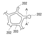
- FIG. 2 is a schematic view showing the porous aluminum body of the present invention.
- a substantially spherical portion 202 is provided at the end of the skeleton structure 203 having a three-dimensional network structure.
- the metal material is aluminum. Since aluminum is a lightweight material with excellent conductivity, good characteristics can be obtained when a metal porous body is used as a battery electrode material.
- the diameter of the substantially spherical portion is larger than the outer diameter of the skeleton structure. If the diameter of the substantially spherical portion is large, when the active material is supported on the metal porous body, the active material supported is caught on the substantially spherical portion, so that the active material does not easily fall off.
- the outer diameter of the skeleton structure is the diameter of the cross section at the center of the skeleton structure, and when the cross section is not a circle, it is the diameter when the cross section is approximated to a circle.
- FIG. 3 shows an example of the skeleton structure of the porous metal body of the present invention, and is a cross-sectional view taken along the line A-A ′ of FIG. As shown in FIG. 3, the cross section of the skeleton structure has a substantially triangular shape. In this case, the diameter a of the circle passing through the three vertices of the triangle is the diameter of the skeleton structure.
- B is the thickness of the metal layer.
- the outer diameter of the substantially triangular shape is 100 ⁇ m or more and 250 ⁇ m or less, and the thickness of the metal layer is 0.5 ⁇ m or more and 10 ⁇ m.
- the porosity of the metal porous body can be increased.
- the metal porous body is in the form of a sheet having a thickness of 1000 ⁇ m to 3000 ⁇ m, and the basis weight (amount of aluminum per unit area) at a thickness of 1000 ⁇ m is preferably 120 g / m 2 or more and 180 g / m 2 or less.
- a metal porous body is suitable as an electrode material for a battery.
- a battery using the above electrode material for one or both of the positive electrode and the negative electrode can be obtained.
- the capacity of the battery can be increased.
- the present invention contains 1,10-phenanthroline at a concentration of 0.1 g / l or more and 10 g / l or less and a temperature of 40 ° C. or more and 100 ° C. in a resin molded body having a three-dimensional network structure with at least a surface conductive.
- a method for producing a porous metal body which comprises a step of plating aluminum in a molten salt bath at a temperature of 0 ° C. or lower.
- it is a porous metal body having a three-dimensional network structure, and it can be used as an electrode material that can be obtained with good electrical characteristics with little deterioration in performance in a pressing process and a compression process when producing an electrode material.
- a porous metal body and a method for producing the same, and an electrode material and a battery using the porous metal body can be provided.
- FIG. 3 is a schematic view showing a porous aluminum body of the present invention, and is a cross-sectional view taken along the line A-A ′ of FIG.
- FIG. 3 is a schematic view showing a porous aluminum body of the present invention, and is a cross-sectional view taken along the line A-A ′ of FIG.
- It is a surface enlarged photograph which shows the structure of the urethane foam as an example of the resin molding which has a three-dimensional network structure. It is a figure explaining an example of the continuous electroconductivity process of the resin molding body surface with an electroconductive coating material.
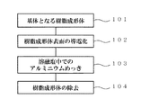
- FIG. 4 is a flow chart showing the manufacturing process of the aluminum porous body according to the present invention.
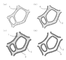
- FIG. 5 schematically shows a state in which a porous aluminum body is formed using a resin molded body having a three-dimensional network structure as a core material corresponding to the flow diagram. The flow of the entire manufacturing process will be described with reference to both drawings.
- preparation 101 of a resin molded body to be a base is performed.
- FIG. 5A is an enlarged schematic view in which the surface of a resin molded body (foamed resin molded body) having a three-dimensional network structure is enlarged as an example of a resin molded body serving as a base.
- the pores are formed with the foamed resin molded body 1 as a skeleton.
- the surface 102 of the resin molded body is made conductive.
- a thin conductive layer 2 made of a conductor is formed on the surface of the resin molded body 1.
- aluminum plating 103 in molten salt is performed to form the aluminum plating layer 3 on the surface of the resin molded body on which the conductive layer is formed (FIG. 5C).
- an aluminum porous body having the resin molded body as a base and the aluminum plating layer 3 formed on the surface is obtained.
- removal 104 of the resin molded body serving as the base may be performed.
- a porous aluminum body in which only the metal layer remains can be obtained (FIG. 5D).
- each step will be described in order.
- a resin molded body having a three-dimensional network structure is prepared. Any resin can be selected as the material of the resin molded body. Examples of the material include foamed resin moldings such as polyurethane, melamine resin, polypropylene, and polyethylene.
- the resin molded body having a three-dimensional network structure preferably has a porosity of 80% to 98% and a pore diameter of 50 ⁇ m to 500 ⁇ m.
- Urethane foam and foamed melamine can be preferably used as a resin molded article because they have high porosity, have pore connectivity and are excellent in thermal decomposability. Foamed urethane is preferred in terms of pore uniformity and availability, and foamed melamine is preferred in that a product having a small pore diameter can be obtained.
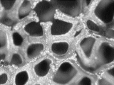
- FIG. 6 shows an example of a resin molded body having a three-dimensional network structure that has been subjected to a cleaning treatment using urethane foam as a pretreatment.
- the resin molded body forms a three-dimensional network as a skeleton, thereby forming continuous pores as a whole.
- the urethane skeleton has a substantially triangular shape in a cross section perpendicular to the extending direction.
- the porosity is defined by the following equation.
- Porosity (1 ⁇ (weight of porous material [g] / (volume of porous material [cm 3 ] ⁇ material density))) ⁇ 100 [%]
- the suspension as the conductive paint preferably contains carbon particles, a binder, a dispersant and a dispersion medium.
- the suspension In order to uniformly apply the conductive particles, the suspension needs to maintain a uniform suspension state. For this reason, the suspension is preferably maintained at 20 ° C. to 40 ° C. The reason is that when the temperature of the suspension is lower than 20 ° C., the uniform suspension state is lost, and only the binder is concentrated on the surface of the skeleton forming the network structure of the resin molded body to form a layer. Because. In this case, the applied carbon particle layer is easy to peel off, and it is difficult to form a metal plating that is firmly adhered.
- the particle size of the carbon particles is 0.01 to 5 ⁇ m, preferably 0.01 to 0.5 ⁇ m. If the particle size is large, the pores of the resin molded body are clogged or smooth plating is hindered. If it is too small, it is difficult to ensure sufficient conductivity.
- FIG. 7 is a diagram schematically illustrating a configuration example of a processing apparatus that conducts a band-shaped resin molded body serving as a skeleton as an example of a practical manufacturing process.
- this apparatus includes a supply bobbin 12 for supplying a belt-shaped resin 11, a tank 15 containing a conductive paint suspension 14, a pair of squeezing rolls 17 disposed above the tank 15, A plurality of hot air nozzles 16 provided to face the side of the belt-shaped resin 11 to be wound, and a winding bobbin 18 that winds up the belt-shaped resin 11 after processing.
- a deflector roll 13 for guiding the belt-shaped resin 11 is appropriately disposed.
- the strip-shaped resin 11 having a three-dimensional network structure is unwound from the supply bobbin 12, guided by the deflector roll 13, and immersed in the suspension in the tank 15.
- the strip-shaped resin 11 immersed in the suspension 14 in the tank 15 changes its direction upward and travels between the squeeze rolls 17 above the liquid level of the suspension 14. At this time, the distance between the squeezing rolls 17 is smaller than the thickness of the belt-shaped resin 11, and the belt-shaped resin 11 is compressed. Therefore, the excess suspension impregnated in the belt-shaped resin 11 is squeezed out and returned to the tank 15.
- the strip-shaped resin 11 changes the traveling direction again.
- the suspension dispersion medium and the like are removed by hot air jetted by the hot air nozzle 16 composed of a plurality of nozzles, and the belt-like resin 11 is wound around the winding bobbin 18 after sufficiently drying.
- the temperature of the hot air ejected from the hot air nozzle 16 is preferably in the range of 40 ° C to 80 ° C.
- Formation of aluminum layer molten salt plating
- electrolytic plating is performed in a molten salt to form an aluminum plating layer on the surface of the resin molded body.
- a direct current is applied in a molten salt using a resin molded body having a conductive surface as a cathode and an aluminum plate having a purity of 99.99% as an anode.
- a mixed salt (eutectic salt) of aluminum chloride and an organic salt is used.
- Use of an organic molten salt bath that melts at a relatively low temperature is preferable because plating can be performed without decomposing the resin molded body as a substrate.
- the organic salt imidazolium salt, pyridinium salt and the like can be used. Of these, 1-ethyl-3-methylimidazolium chloride (EMIC) and butylpyridinium chloride (BPC) are preferable.
- EMIC 1-ethyl-3-methylimidazolium chloride
- BPC butylpyr
- the temperature of the molten salt bath is set to 40 ° C. or higher and 100 ° C. or lower.
- the viscosity cannot be lowered sufficiently.
- an organic salt may decompose
- a more preferable temperature is 50 ° C. or higher and 80 ° C. or lower. Since the molten salt deteriorates when moisture or oxygen is mixed in the molten salt, the plating is preferably performed in an atmosphere of an inert gas such as nitrogen or argon and in a sealed environment.
- 1,10-phenanthroline it is preferable to add 1,10-phenanthroline to the molten salt bath because the surface becomes smooth and a substantially spherical portion can be formed at the end of the skeletal structure.
- the amount of 1,10-phenanthroline added is preferably 0.25 g / l or more and 7 g / l or less. The end tends to be rounded as the amount added is increased. When the addition amount is less than 0.25 g / l, it is difficult to obtain the effect of efficiently forming a substantially spherical portion at the end of the skeleton structure and the effect of smoothing the surface of the skeleton structure.
- a more preferable range of the addition amount is 2.5 g / l or more and 5 g / l or less.
- the substantially spherical portion includes not only a perfect spherical shape but also a part of a spherical shape, for example, a hemispherical shape.
- the metal layer is cylindrical at the center of the skeleton structure, but at the end of the skeleton structure, a substantially spherical portion closes the end of the cylinder.
- the diameter of the substantially spherical portion is preferably larger than the outer diameter of the skeleton structure.
- the diameter of the substantially spherical portion is preferably 20 ⁇ m or more and 50 ⁇ m or less, and more preferably 30 ⁇ m or more and 40 ⁇ m or less.
- FIG. 8 is a diagram schematically showing a configuration of an apparatus for continuously performing metal plating on the above-described belt-shaped resin.
- a configuration in which the belt-like resin 22 whose surface is made conductive is sent from the left to the right in the figure.
- the first plating tank 21a includes a cylindrical electrode 24, an anode 25 provided on the inner wall of the container, and a plating bath 23. By passing the strip-shaped resin 22 through the plating bath 23 along the cylindrical electrode 24, a uniform current can easily flow through the entire resin molded body, and uniform plating can be obtained.
- the second plating tank 21b is a tank for applying a thicker and more uniform plating, and is configured to be repeatedly plated in a plurality of tanks.
- Plating is performed by passing the belt-like resin 22 having a conductive surface through a plating bath 28 while sequentially feeding the belt-like resin 22 by an electrode roller 26 that also serves as a feeding roller and an out-of-vessel feeding cathode.
- anodes 27 provided on both surfaces of the resin molded body via a plating bath 28, and uniform plating can be applied to both surfaces of the resin molded body.
- skeleton core by the above process is obtained.
- the resin and metal composite may be used as they are.
- the resin may be removed when used as a porous metal body having no resin due to restrictions on the use environment. Removal of the resin can be performed by any method such as decomposition (dissolution) with an organic solvent, molten salt, or supercritical water, and thermal decomposition. Since aluminum is difficult to reduce once oxidized, unlike nickel or the like, for example, when used as an electrode material for a battery or the like, it is preferable to remove the resin by a method in which oxidation of aluminum hardly occurs. For example, a method of removing the resin by thermal decomposition in a molten salt described below is preferably used.
- Thermal decomposition in the molten salt is performed by the following method.
- a resin molded body having an aluminum plating layer formed on the surface is immersed in a molten salt and heated while applying a negative potential to the aluminum layer to decompose the resin molded body.
- the heating temperature can be appropriately selected according to the type of the resin molded body.
- a preferable temperature range is 500 ° C. or more and 600 ° C. or less.
- the amount of negative potential to be applied is on the minus side of the reduction potential of aluminum and on the plus side of the reduction potential of cations in the molten salt.
- an alkali metal or alkaline earth metal halide salt or nitrate which can lower the electrode potential of aluminum can be used.
- lithium cobaltate (LiCoO 2 ), lithium manganate (LiMn 2 O 4 ), lithium nickelate (LiNiO 2 ), or the like is used as an active material.
- the active material is used in combination with a conductive additive and a binder.
- Conventional positive electrode materials for lithium ion batteries have an active material coated on the surface of an aluminum foil. In order to improve the battery capacity per unit area, the coating thickness of the active material is increased. In order to effectively use the active material, the aluminum foil and the active material need to be in electrical contact with each other, so that the active material is used in combination with a conductive additive.
- the porous aluminum body of the present invention has a high porosity and a large surface area per unit area. Therefore, even if the active material is thinly supported on the surface of the porous body, the active material can be used effectively, the capacity of the battery can be improved, and the mixing amount of the conductive auxiliary agent can be reduced.
- a sheet-like aluminum porous body having a thickness of 1000 ⁇ m or more and 3000 ⁇ m or less is prepared, and the active material is applied to the aluminum porous body by applying a paste mixed with the above active material, a conductive additive, a binder resin, etc. to the aluminum porous body.
- the positive electrode of the lithium ion battery is supported.
- the lithium ion battery uses this positive electrode material as a positive electrode, graphite as the negative electrode, and organic electrolyte as the electrolyte. Since such a lithium ion battery can improve capacity even with a small electrode area, the energy density of the battery can be made higher than that of a conventional lithium ion battery.
- the aluminum porous body can also be used as an electrode material for a molten salt battery.
- a metal compound capable of intercalating cations of a molten salt serving as an electrolyte such as sodium chromate (NaCrO 2 ) and titanium disulfide (TiS 2 ), is used as an active material.
- the active material is used in combination with a conductive additive and a binder.
- a conductive assistant acetylene black or the like can be used.
- the binder polytetrafluoroethylene (PTFE) or the like can be used.
- PTFE polytetrafluoroethylene
- the aluminum porous body can also be used as a negative electrode material for a molten salt battery.
- an aluminum porous body is used as a negative electrode material
- sodium alone, an alloy of sodium and another metal, carbon, or the like can be used as an active material.
- the melting point of sodium is about 98 ° C., and the metal softens as the temperature rises. Therefore, it is preferable to alloy sodium with other metals (Si, Sn, In, etc.). Of these, an alloy of sodium and Sn is particularly preferable because it is easy to handle.
- Sodium or a sodium alloy can be supported on the surface of the porous aluminum body by a method such as electrolytic plating or hot dipping.
- a metal (such as Si) that is alloyed with sodium is attached to the aluminum porous body by a method such as plating, a sodium alloy can be obtained by charging in a molten salt battery.
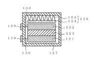
- FIG. 9 is a schematic sectional view showing an example of a molten salt battery using the battery electrode material.
- the molten salt battery includes a positive electrode 121 carrying a positive electrode active material on the surface of an aluminum skeleton part of an aluminum porous body, a negative electrode 122 carrying a negative electrode active material on the surface of the aluminum skeleton part of an aluminum porous body, and an electrolyte.
- a separator 123 impregnated with molten salt is housed in a case 127. Between the upper surface of the case 127 and the negative electrode, a pressing member 126 including a pressing plate 124 and a spring 125 that presses the pressing plate is disposed.
- the current collector (aluminum porous body) of the positive electrode 121 and the current collector (aluminum porous body) of the negative electrode 122 are connected to the positive electrode terminal 128 and the negative electrode terminal 129 by lead wires 130, respectively.
- molten salt As the electrolyte, various inorganic salts or organic salts that melt at the operating temperature can be used.
- alkali metals such as lithium (Li), sodium (Na), potassium (K), rubidium (Rb) and cesium (Cs), beryllium (Be), magnesium (Mg), calcium (Ca)
- strontium (Sr) and barium (Ba) can be used.
- the operating temperature of the battery can be reduced to 90 ° C. or less.
- a separator is for preventing a positive electrode and a negative electrode from contacting, and a glass nonwoven fabric, a porous resin molding, etc. can be used.
- the above positive electrode, negative electrode, and separator impregnated with molten salt are stacked and housed in a case to be used as a battery.
- the aluminum porous body can also be used as an electrode material for an electric double layer capacitor.
- activated carbon or the like is used as an electrode active material.
- Activated carbon is used in combination with a conductive aid and a binder.
- conductive auxiliary agent graphite, carbon nanotube, etc. can be used.
- binder polytetrafluoroethylene (PTFE), styrene butadiene rubber or the like can be used.
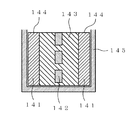
- FIG. 10 is a schematic cross-sectional view showing an example of an electric double layer capacitor using the above electrode material for an electric double layer capacitor.
- an electrode material in which an electrode active material is supported on a porous aluminum body is disposed as a polarizable electrode 141.
- the polarizable electrode 141 is connected to the lead wire 144 and is entirely housed in the case 145.
- an aluminum porous body as a current collector, the surface area of the current collector is increased, and an electric double layer capacitor capable of high output and high capacity can be obtained even when activated carbon as an active material is thinly applied. .
- Example 1 (Formation of conductive layer: carbon coating)
- a production example of the aluminum porous body As a resin molded body having a three-dimensional network structure, urethane foam having a thickness of 1 mm, a porosity of 95%, and a pore diameter of 300 ⁇ m was prepared and cut into 80 mm ⁇ 50 mm squares. By immersing urethane foam in a carbon suspension and drying, a conductive layer having carbon particles attached to the entire surface was formed.
- the components of the suspension include graphite + carbon black 25%, and include a resin binder, a penetrating agent, and an antifoaming agent.
- the particle size of carbon black was 0.5 ⁇ m.
- Example 2 Except that the phenanthroline concentration in the plating bath was 0.25 g / l, the same operation as in Example 1 was performed to obtain a porous aluminum body. The surface enlarged photograph of the obtained aluminum porous body is shown in FIG.
- Example 1 A porous aluminum body was obtained in the same manner as in Example 1 except that 17 mol% EMIC-34 mol% AlCl 3 -49 mol% xylene was used as the plating bath and the temperature of the plating bath was 40 ° C. The surface enlarged photograph of the obtained aluminum porous body is shown in FIG.
- the porous aluminum body of Example 1 having a phenanthroline concentration in the plating bath of 5 g / l has a substantially spherical portion formed at the end, and the diameter of the substantially spherical portion is that of the skeleton portion. It is larger than the diameter.
- the porous aluminum body of Example 2 having a phenanthroline concentration of 0.25 g / l has a substantially spherical portion formed at the end, but the diameter of the substantially spherical portion is larger than the diameter of the skeleton portion. Is also small.
- the aluminum porous body of the comparative example plated by adding an organic solvent (xylene) without adding phenanthroline does not form a substantially spherical portion at the end, and the strength at the end of the skeletal structure is weakened. I guess that.
Landscapes
- Chemical & Material Sciences (AREA)
- Chemical Kinetics & Catalysis (AREA)
- Electrochemistry (AREA)
- Engineering & Computer Science (AREA)
- Materials Engineering (AREA)
- Metallurgy (AREA)
- Organic Chemistry (AREA)
- General Chemical & Material Sciences (AREA)
- Manufacturing & Machinery (AREA)
- Cell Electrode Carriers And Collectors (AREA)
- Electroplating Methods And Accessories (AREA)
Abstract
Description
図4は、本発明によるアルミニウム多孔体の製造工程を示すフロー図である。また図5は、フロー図に対応して三次元網目構造を有する樹脂成形体を芯材としてアルミニウム多孔体を形成する様子を模式的に示したものである。両図を参照して製造工程全体の流れを説明する。まず基体となる樹脂成形体の準備101を行う。図5(a)は、基体となる樹脂成形体の例として、三次元網目構造を有する樹脂成形体(発泡樹脂成形体)の表面を拡大視した拡大模式図である。発泡樹脂成形体1を骨格として気孔が形成されている。次に樹脂成形体表面の導電化102を行う。この工程により、図5(b)に示すように樹脂成形体1の表面には薄く導電体による導電層2が形成される。続いて溶融塩中でのアルミニウムめっき103を行い、導電層が形成された樹脂成形体の表面にアルミニウムめっき層3を形成する(図5(c))。これで、樹脂成形体を基体として表面にアルミニウムめっき層3が形成されたアルミニウム多孔体が得られる。さらに、基体となる樹脂成形体の除去104を行っても良い。発泡樹脂成形体1を分解等して消失させることにより金属層のみが残ったアルミニウム多孔体を得ることができる(図5(d))。以下各工程について順を追って説明する。
三次元網目構造を有する樹脂成形体を準備する。樹脂成形体の素材は任意の樹脂を選択できる。ポリウレタン、メラミン樹脂、ポリプロピレン、ポリエチレン等の発泡樹脂成形体が素材として例示できる。三次元網目構造を有する樹脂成形体の気孔率は80%~98%、気孔径は50μm~500μmとするのが好ましい。発泡ウレタン及び発泡メラミンは気孔率が高く、また気孔の連通性があるとともに熱分解性にも優れているため樹脂成形体として好ましく使用できる。発泡ウレタンは気孔の均一性や入手の容易さ等の点で好ましく、発泡メラミンは気孔径の小さなものが得られる点で好ましい。
気孔率=(1-(多孔質材の重量[g]/(多孔質材の体積[cm3]×素材密度)))×100[%]
また、気孔径は、樹脂成形体表面を顕微鏡写真等で拡大し、1インチ(25.4mm)あたりの気孔数をセル数として計数して、平均孔径=25.4mm/セル数として平均的な値を求める。
導電性塗料としてのカーボン塗料を準備する。導電性塗料としての懸濁液は、好ましくは、カーボン粒子、粘結剤、分散剤および分散媒を含む。導電性粒子の塗布を均一に行うには、懸濁液が均一な懸濁状態を維持している必要がある。このため、懸濁液は、20℃~40℃に維持されていることが好ましい。その理由は、懸濁液の温度が20℃未満になった場合、均一な懸濁状態が崩れ、樹脂成形体の網目構造をなす骨格の表面に粘結剤のみが集中して層を形成するからである。この場合、塗布されたカーボン粒子の層は剥離し易く、強固に密着した金属めっきを形成し難い。一方、懸濁液の温度が40℃を越えた場合は、分散剤の蒸発量が大きく、塗布処理時間の経過とともに懸濁液が濃縮されてカーボンの塗布量が変動しやすい。また、カーボン粒子の粒径は、0.01~5μmで、好ましくは0.01~0.5μmである。粒径が大きいと樹脂成形体の空孔を詰まらせたり、平滑なめっきを阻害する要因となり、小さすぎると十分な導電性を確保することが難しくなる。
次に溶融塩中で電解めっきを行い、樹脂成形体表面にアルミニウムめっき層を形成する。表面が導電化された樹脂成形体を陰極、純度99.99%のアルミニウム板を陽極として溶融塩中で直流電流を印加する。溶融塩としては、塩化アルミニウムと有機塩との混合塩(共晶塩)を使用する。比較的低温で溶融する有機溶融塩浴を使用すると、基体である樹脂成形体を分解することなくめっきができ好ましい。有機塩としてはイミダゾリウム塩、ピリジニウム塩等が使用できる。なかでも1-エチル-3-メチルイミダゾリウムクロライド(EMIC)、ブチルピリジニウムクロライド(BPC)が好ましい。
溶融塩中での熱分解は以下の方法で行う。表面にアルミニウムめっき層を形成した樹脂成形体を溶融塩に浸漬し、アルミニウム層に負電位を印加しながら加熱して樹脂成形体を分解する。溶融塩に浸漬した状態で負電位を印加すると、アルミニウムを酸化させることなく樹脂成形体を分解することができる。加熱温度は樹脂成形体の種類に合わせて適宜選択できるが、アルミニウムを溶融させないためにはアルミニウムの融点(660℃)以下の温度で処理する必要がある。好ましい温度範囲は500℃以上600℃以下である。また印加する負電位の量は、アルミニウムの還元電位よりマイナス側で、かつ溶融塩中のカチオンの還元電位よりプラス側とする。
次にアルミニウム多孔体を用いた電池用電極材料及び電池について説明する。例えばリチウムイオン電池の正極に使用する場合は、活物質としてコバルト酸リチウム(LiCoO2)、マンガン酸リチウム(LiMn2O4)、ニッケル酸リチウム(LiNiO2)等を使用する。活物質は導電助剤及びバインダーと組み合わせて使用する。従来のリチウムイオン電池用正極材料は、アルミニウム箔の表面に活物質を塗布している。単位面積当たりの電池容量を向上するために、活物質の塗布厚みを厚くしている。また活物質を有効に利用するためにはアルミニウム箔と活物質とが電気的に接触している必要があるので活物質は導電助剤と混合して用いられている。
アルミニウム多孔体は、溶融塩電池用の電極材料として使用することもできる。アルミニウム多孔体を正極材料として使用する場合は、活物質としてクロム酸ナトリウム(NaCrO2)、二硫化チタン(TiS2)等、電解質となる溶融塩のカチオンをインターカレーションすることができる金属化合物を使用する。活物質は導電助剤及びバインダーと組み合わせて使用する。導電助剤としてはアセチレンブラック等が使用できる。またバインダーとしてはポリテトラフルオロエチレン(PTFE)等を使用できる。活物質としてクロム酸ナトリウムを使用し、導電助剤としてアセチレンブラックを使用する場合には、PTFEはこの両者をより強固に固着することができ好ましい。
アルミニウム多孔体は、電気二重層コンデンサ用の電極材料として使用することもできる。アルミニウム多孔体を電気二重層コンデンサ用の電極材料として使用する場合は、電極活物質として活性炭等を使用する。活性炭は導電助剤やバインダーと組み合わせて使用する。導電助剤としては黒鉛、カーボンナノチューブ等が使用できる。またバインダーとしてはポリテトラフルオロエチレン(PTFE)、スチレンブタジエンゴム等を使用できる。
(導電層の形成:カーボン塗布)
以下、アルミニウム多孔体の製造例を具体的に説明する。三次元網目構造を有する樹脂成形体として、厚み1mm、気孔率95%、気孔径300μmの発泡ウレタンを準備し、80mm×50mm角に切断した。発泡ウレタンをカーボン懸濁液に浸漬し乾燥することで、表面全体にカーボン粒子が付着した導電層を形成した。懸濁液の成分は、黒鉛+カーボンブラック25%を含み、樹脂バインダー、浸透剤、消泡剤を含む。カーボンブラックの粒径は0.5μmとした。
表面に導電層を形成した発泡ウレタンをワークとして、給電機能を有する治具にセットした後、アルゴン雰囲気かつ低水分(露点-30℃以下)としたグローブボックス内に入れ、フェナントロリンを5g/l添加した溶融塩浴(33mol%EMIC-67mol%AlCl3)に浸漬した。ワークをセットした治具を整流器の陰極側に接続し、対極のアルミニウム板(純度99.99%)を陽極側に接続し、直流電流を印加してアルミニウムをめっきした。めっき浴の温度は60℃とした。
アルミニウムめっき層を形成したそれぞれの樹脂成形体を温度500℃のLiCl-KCl共晶溶融塩に浸漬し-1Vの負電位を5分間印加してポリウレタンを分解除去してアルミニウム多孔体を得た。得られたアルミニウム多孔体の表面拡大写真を図11に示す。
めっき浴中のフェナントロリン濃度を0.25g/lとしたこと以外は実施例1と同様の操作を行い、アルミニウム多孔体を得た。得られたアルミニウム多孔体の表面拡大写真を図12に示す。
めっき浴として17mol%EMIC-34mol%AlCl3-49mol%キシレンを用い、めっき浴の温度を40℃とした以外は実施例1と同様の操作を行い、アルミニウム多孔体を得た。得られたアルミニウム多孔体の表面拡大写真を図1に示す。
11 帯状樹脂 12 サプライボビン 13 デフレクタロール 14 懸濁液
15 槽 16 熱風ノズル 17 絞りロール 18 巻取りボビン
21a,21b めっき槽 22 帯状樹脂 23,28 めっき浴
24 円筒状電極 25,27 陽極 26 電極ローラ
121 正極 122 負極 123 セパレータ 124 押さえ板
125 バネ 126 押圧部材 127 ケース 128 正極端子
129 負極端子 130 リード線
141 分極性電極 142 セパレータ 143 有機電解液
144 リード線 145 ケース
201 角部 202 略球状部 203 骨格構造
Claims (8)
- 金属層からなる骨格構造が三次元網目構造をなしており、前記骨格構造の端部に略球状部を有することを特徴とする金属多孔体。
- 前記金属がアルミニウムである、請求項1に記載の金属多孔体。
- 前記略球状部の径が、前記骨格構造の外径よりも大きいことを特徴とする請求項1又は2に記載の金属多孔体。
- 前記骨格構造の断面は略三角形であり、該三角形の外径が100μm以上250μm以下、金属層の厚みが0.5μm以上10μm以下である、請求項1~3のいずれか1項に記載の金属多孔体。
- 前記金属多孔体は厚み1000μm以上3000μm以下のシート状であり、厚み1000μmでの単位面積あたりのアルミニウム量が、120g/m2以上180g/m2以下である、請求項1~4のいずれか一項に記載の金属多孔体。
- 請求項1~5のいずれか1項に記載の金属多孔体に活物質を担持した電極材料。
- 請求項6に記載の電極材料を正極、負極の一方又は両方に用いた電池。
- 請求項2に記載の金属多孔体の製造方法であって、少なくとも表面が導電化された三次元網目構造を有する樹脂成形体に、1,10-フェナントロリンを0.1g/l以上10g/l以下の濃度で含有するとともに温度40℃以上100℃以下の溶融塩浴中でアルミニウムをめっきする工程を有する、金属多孔体の製造方法。
Priority Applications (4)
| Application Number | Priority Date | Filing Date | Title |
|---|---|---|---|
| KR1020137028869A KR20140021638A (ko) | 2011-06-03 | 2012-05-22 | 금속 다공체 및 그것을 이용한 전극 재료, 전지 |
| CN201280027230.6A CN103597126A (zh) | 2011-06-03 | 2012-05-22 | 金属多孔体、以及均包括该金属多孔体的电极材料和电池 |
| DE112012002349.8T DE112012002349T5 (de) | 2011-06-03 | 2012-05-22 | Poröser Metallkörper und Elektrodenmaterial und Batterie, die beide den Körper beinhalten |
| US13/648,637 US20130122375A1 (en) | 2011-06-03 | 2012-10-10 | Porous metal body, and electrode material and battery both incorporating the body |
Applications Claiming Priority (2)
| Application Number | Priority Date | Filing Date | Title |
|---|---|---|---|
| JP2011-124706 | 2011-06-03 | ||
| JP2011124706A JP2012251210A (ja) | 2011-06-03 | 2011-06-03 | 金属多孔体及びそれを用いた電極材料、電池 |
Related Child Applications (1)
| Application Number | Title | Priority Date | Filing Date |
|---|---|---|---|
| US13/648,637 Continuation US20130122375A1 (en) | 2011-06-03 | 2012-10-10 | Porous metal body, and electrode material and battery both incorporating the body |
Publications (1)
| Publication Number | Publication Date |
|---|---|
| WO2012165213A1 true WO2012165213A1 (ja) | 2012-12-06 |
Family
ID=47259074
Family Applications (1)
| Application Number | Title | Priority Date | Filing Date |
|---|---|---|---|
| PCT/JP2012/063006 Ceased WO2012165213A1 (ja) | 2011-06-03 | 2012-05-22 | 金属多孔体及びそれを用いた電極材料、電池 |
Country Status (6)
| Country | Link |
|---|---|
| US (1) | US20130122375A1 (ja) |
| JP (1) | JP2012251210A (ja) |
| KR (1) | KR20140021638A (ja) |
| CN (1) | CN103597126A (ja) |
| DE (1) | DE112012002349T5 (ja) |
| WO (1) | WO2012165213A1 (ja) |
Cited By (1)
| Publication number | Priority date | Publication date | Assignee | Title |
|---|---|---|---|---|
| JP2015137378A (ja) * | 2014-01-21 | 2015-07-30 | 住友電気工業株式会社 | アルミニウム膜の製造方法及び製造装置 |
Families Citing this family (7)
| Publication number | Priority date | Publication date | Assignee | Title |
|---|---|---|---|---|
| JP6252220B2 (ja) * | 2014-02-12 | 2017-12-27 | 住友電気工業株式会社 | ナトリウムイオン二次電池、充放電方法および充放電システム |
| JP6318689B2 (ja) | 2014-02-20 | 2018-05-09 | 日立金属株式会社 | 電解アルミニウム箔およびその製造方法、蓄電デバイス用集電体、蓄電デバイス用電極、蓄電デバイス |
| CN104745853B (zh) * | 2015-04-23 | 2017-01-18 | 苏州第一元素纳米技术有限公司 | 一种泡沫铝/纳米碳复合材料的制备方法 |
| JP6393784B2 (ja) * | 2015-09-07 | 2018-09-19 | シク ジュ,ハク | 電磁波吸収消滅および遮蔽用ならびに電子機器高放熱用融合シート、および、その製造方法 |
| CN107658472B (zh) * | 2016-07-25 | 2020-12-15 | 株式会社Lg 化学 | 包含网眼型集电器的负极、包含其的锂二次电池和其制造方法 |
| JP2021120917A (ja) * | 2018-04-27 | 2021-08-19 | 住友電気工業株式会社 | アルミニウム多孔体、電極および蓄電デバイス |
| CN117328111B (zh) * | 2023-12-01 | 2024-03-08 | 中铝材料应用研究院有限公司 | 一种复合铝箔及其制备方法 |
Citations (4)
| Publication number | Priority date | Publication date | Assignee | Title |
|---|---|---|---|---|
| JPH07138609A (ja) * | 1993-09-14 | 1995-05-30 | Katayama Tokushu Kogyo Kk | 金属多孔体および該金属多孔体の製造方法 |
| JP2008195990A (ja) * | 2007-02-09 | 2008-08-28 | Dipsol Chem Co Ltd | 電気アルミニウムめっき浴及びそれを用いためっき方法 |
| JP2010037569A (ja) * | 2008-07-31 | 2010-02-18 | Mitsubishi Materials Corp | 金属多孔質電極基材およびその製造方法 |
| JP2010232171A (ja) * | 2009-03-05 | 2010-10-14 | Hitachi Metals Ltd | アルミニウム多孔質材およびその製造方法、アルミニウム多孔質材を電極集電体として用いた蓄電デバイス |
Family Cites Families (5)
| Publication number | Priority date | Publication date | Assignee | Title |
|---|---|---|---|---|
| US7628903B1 (en) * | 2000-05-02 | 2009-12-08 | Ishihara Chemical Co., Ltd. | Silver and silver alloy plating bath |
| US7846574B2 (en) * | 2004-08-27 | 2010-12-07 | Panosonic Corporation | Positive electrode plate for alkaline storage battery and method for producing the same |
| US7316878B2 (en) * | 2004-08-30 | 2008-01-08 | Samsung Electronics Co., Ltd. | Hydrazone-based charge transport materials having an unsaturated acyl group |
| JP5023645B2 (ja) * | 2006-02-28 | 2012-09-12 | パナソニック株式会社 | アルカリ蓄電池 |
| JP5270846B2 (ja) * | 2007-02-09 | 2013-08-21 | ディップソール株式会社 | 常温溶融塩浴を用いた電気Al−Zr合金めっき浴とそれを用いるめっき方法 |
-
2011
- 2011-06-03 JP JP2011124706A patent/JP2012251210A/ja active Pending
-
2012
- 2012-05-22 DE DE112012002349.8T patent/DE112012002349T5/de not_active Withdrawn
- 2012-05-22 CN CN201280027230.6A patent/CN103597126A/zh active Pending
- 2012-05-22 KR KR1020137028869A patent/KR20140021638A/ko not_active Withdrawn
- 2012-05-22 WO PCT/JP2012/063006 patent/WO2012165213A1/ja not_active Ceased
- 2012-10-10 US US13/648,637 patent/US20130122375A1/en not_active Abandoned
Patent Citations (4)
| Publication number | Priority date | Publication date | Assignee | Title |
|---|---|---|---|---|
| JPH07138609A (ja) * | 1993-09-14 | 1995-05-30 | Katayama Tokushu Kogyo Kk | 金属多孔体および該金属多孔体の製造方法 |
| JP2008195990A (ja) * | 2007-02-09 | 2008-08-28 | Dipsol Chem Co Ltd | 電気アルミニウムめっき浴及びそれを用いためっき方法 |
| JP2010037569A (ja) * | 2008-07-31 | 2010-02-18 | Mitsubishi Materials Corp | 金属多孔質電極基材およびその製造方法 |
| JP2010232171A (ja) * | 2009-03-05 | 2010-10-14 | Hitachi Metals Ltd | アルミニウム多孔質材およびその製造方法、アルミニウム多孔質材を電極集電体として用いた蓄電デバイス |
Cited By (1)
| Publication number | Priority date | Publication date | Assignee | Title |
|---|---|---|---|---|
| JP2015137378A (ja) * | 2014-01-21 | 2015-07-30 | 住友電気工業株式会社 | アルミニウム膜の製造方法及び製造装置 |
Also Published As
| Publication number | Publication date |
|---|---|
| DE112012002349T5 (de) | 2014-02-27 |
| CN103597126A (zh) | 2014-02-19 |
| JP2012251210A (ja) | 2012-12-20 |
| KR20140021638A (ko) | 2014-02-20 |
| US20130122375A1 (en) | 2013-05-16 |
Similar Documents
| Publication | Publication Date | Title |
|---|---|---|
| JP5663938B2 (ja) | アルミニウム構造体の製造方法およびアルミニウム構造体 | |
| WO2011132538A1 (ja) | アルミニウム構造体の製造方法およびアルミニウム構造体 | |
| WO2012096220A1 (ja) | アルミニウム構造体の製造方法およびアルミニウム構造体 | |
| JP5883288B2 (ja) | 集電体用三次元網状アルミニウム多孔体、該アルミニウム多孔体を用いた集電体、電極、非水電解質電池、キャパシタ及びリチウムイオンキャパシタ | |
| JPWO2012111605A1 (ja) | 集電体用三次元網状アルミニウム多孔体、該アルミニウム多孔体を用いた集電体及び該集電体を用いた電極並びに該電極を用いた非水電解質電池、キャパシタ及びリチウムイオンキャパシタ | |
| WO2012165213A1 (ja) | 金属多孔体及びそれを用いた電極材料、電池 | |
| WO2012111615A1 (ja) | 空気電池および電極 | |
| JPWO2012111608A1 (ja) | 三次元網状アルミニウム多孔体を用いた集電体及び該集電体を用いた電極並びに該電極を用いた非水電解質電池、非水電解液を用いたキャパシタ及びリチウムイオンキャパシタ並びに電極の製造方法 | |
| JP5648588B2 (ja) | アルミニウム構造体の製造方法およびアルミニウム構造体 | |
| JP5803301B2 (ja) | アルミニウム多孔体の製造方法及び製造装置 | |
| WO2012111705A1 (ja) | 集電体用三次元網状アルミニウム多孔体及び該アルミニウム多孔体を用いた電極並びに該電極を用いた非水電解質電池、非水電解液キャパシタ及びリチウムイオンキャパシタ | |
| JP5704026B2 (ja) | アルミニウム構造体の製造方法 | |
| JP5692233B2 (ja) | アルミニウム構造体の製造方法およびアルミニウム構造体 | |
| WO2012036065A1 (ja) | アルミニウム構造体の製造方法およびアルミニウム構造体 | |
| JP2011246779A (ja) | アルミニウム構造体の製造方法およびアルミニウム構造体 | |
| JP2013194308A (ja) | 金属多孔体及びそれを用いた電極材料、電池 | |
| JP5488994B2 (ja) | アルミニウム構造体の製造方法およびアルミニウム構造体 | |
| WO2013077245A1 (ja) | アルミニウム多孔体を集電体として用いた電極及びその製造方法 | |
| JP2015083716A (ja) | アルミニウム構造体を含む電極材料、それを用いた電池および電気二重層コンデンサ、ならびにアルミニウム構造体を用いた濾過フィルタおよび触媒担体 | |
| JP5488996B2 (ja) | アルミニウム構造体の製造方法およびアルミニウム構造体 | |
| JP2012255187A (ja) | アルミニウム多孔体の製造方法及び製造装置 |
Legal Events
| Date | Code | Title | Description |
|---|---|---|---|
| 121 | Ep: the epo has been informed by wipo that ep was designated in this application |
Ref document number: 12793909 Country of ref document: EP Kind code of ref document: A1 |
|
| ENP | Entry into the national phase |
Ref document number: 20137028869 Country of ref document: KR Kind code of ref document: A |
|
| WWE | Wipo information: entry into national phase |
Ref document number: 1120120023498 Country of ref document: DE Ref document number: 112012002349 Country of ref document: DE |
|
| 122 | Ep: pct application non-entry in european phase |
Ref document number: 12793909 Country of ref document: EP Kind code of ref document: A1 |