WO2012164795A1 - バックライトおよび液晶表示装置 - Google Patents
バックライトおよび液晶表示装置 Download PDFInfo
- Publication number
- WO2012164795A1 WO2012164795A1 PCT/JP2012/001758 JP2012001758W WO2012164795A1 WO 2012164795 A1 WO2012164795 A1 WO 2012164795A1 JP 2012001758 W JP2012001758 W JP 2012001758W WO 2012164795 A1 WO2012164795 A1 WO 2012164795A1
- Authority
- WO
- WIPO (PCT)
- Prior art keywords
- light
- liquid crystal
- crystal display
- light distribution
- display panel
- Prior art date
Links
Images


Classifications
-
- G—PHYSICS
- G02—OPTICS
- G02F—OPTICAL DEVICES OR ARRANGEMENTS FOR THE CONTROL OF LIGHT BY MODIFICATION OF THE OPTICAL PROPERTIES OF THE MEDIA OF THE ELEMENTS INVOLVED THEREIN; NON-LINEAR OPTICS; FREQUENCY-CHANGING OF LIGHT; OPTICAL LOGIC ELEMENTS; OPTICAL ANALOGUE/DIGITAL CONVERTERS
- G02F1/00—Devices or arrangements for the control of the intensity, colour, phase, polarisation or direction of light arriving from an independent light source, e.g. switching, gating or modulating; Non-linear optics
- G02F1/01—Devices or arrangements for the control of the intensity, colour, phase, polarisation or direction of light arriving from an independent light source, e.g. switching, gating or modulating; Non-linear optics for the control of the intensity, phase, polarisation or colour
- G02F1/13—Devices or arrangements for the control of the intensity, colour, phase, polarisation or direction of light arriving from an independent light source, e.g. switching, gating or modulating; Non-linear optics for the control of the intensity, phase, polarisation or colour based on liquid crystals, e.g. single liquid crystal display cells
- G02F1/133—Constructional arrangements; Operation of liquid crystal cells; Circuit arrangements
- G02F1/1333—Constructional arrangements; Manufacturing methods
- G02F1/1335—Structural association of cells with optical devices, e.g. polarisers or reflectors
- G02F1/1336—Illuminating devices
- G02F1/133615—Edge-illuminating devices, i.e. illuminating from the side
-
- G—PHYSICS
- G02—OPTICS
- G02B—OPTICAL ELEMENTS, SYSTEMS OR APPARATUS
- G02B6/00—Light guides; Structural details of arrangements comprising light guides and other optical elements, e.g. couplings
- G02B6/0001—Light guides; Structural details of arrangements comprising light guides and other optical elements, e.g. couplings specially adapted for lighting devices or systems
- G02B6/0011—Light guides; Structural details of arrangements comprising light guides and other optical elements, e.g. couplings specially adapted for lighting devices or systems the light guides being planar or of plate-like form
- G02B6/0033—Means for improving the coupling-out of light from the light guide
- G02B6/005—Means for improving the coupling-out of light from the light guide provided by one optical element, or plurality thereof, placed on the light output side of the light guide
- G02B6/0053—Prismatic sheet or layer; Brightness enhancement element, sheet or layer
-
- G—PHYSICS
- G02—OPTICS
- G02B—OPTICAL ELEMENTS, SYSTEMS OR APPARATUS
- G02B6/00—Light guides; Structural details of arrangements comprising light guides and other optical elements, e.g. couplings
- G02B6/0001—Light guides; Structural details of arrangements comprising light guides and other optical elements, e.g. couplings specially adapted for lighting devices or systems
- G02B6/0011—Light guides; Structural details of arrangements comprising light guides and other optical elements, e.g. couplings specially adapted for lighting devices or systems the light guides being planar or of plate-like form
- G02B6/0033—Means for improving the coupling-out of light from the light guide
- G02B6/005—Means for improving the coupling-out of light from the light guide provided by one optical element, or plurality thereof, placed on the light output side of the light guide
-
- G—PHYSICS
- G02—OPTICS
- G02B—OPTICAL ELEMENTS, SYSTEMS OR APPARATUS
- G02B6/00—Light guides; Structural details of arrangements comprising light guides and other optical elements, e.g. couplings
- G02B6/0001—Light guides; Structural details of arrangements comprising light guides and other optical elements, e.g. couplings specially adapted for lighting devices or systems
- G02B6/0011—Light guides; Structural details of arrangements comprising light guides and other optical elements, e.g. couplings specially adapted for lighting devices or systems the light guides being planar or of plate-like form
- G02B6/0033—Means for improving the coupling-out of light from the light guide
- G02B6/0058—Means for improving the coupling-out of light from the light guide varying in density, size, shape or depth along the light guide
- G02B6/0061—Means for improving the coupling-out of light from the light guide varying in density, size, shape or depth along the light guide to provide homogeneous light output intensity
Definitions
- FIG. 20 is an enlarged cross-sectional view illustrating a part of a light distribution control member in a liquid crystal display device according to an eighth embodiment.
- FIG. 10 is an enlarged cross-sectional view illustrating a part of a light distribution control member in a liquid crystal display device according to a ninth embodiment.
- FIG. 38 is an enlarged cross-sectional view illustrating a part of a light distribution control member in the liquid crystal display device according to the tenth embodiment.
- Light emitted from the light sources 117A and 117B is incident on the light guide plate 81 from the incident end face of the light guide plate 81 and propagates through the light guide plate 81 while being totally reflected. At that time, a part of the propagation light is reflected by the micro optical element 81a on the back surface of the light guide plate 81 and is emitted from the front surface (light exit surface) of the light guide plate 81 as illumination light.
- the micro optical element 81a converts light propagating inside the light guide plate 81 into light having a light distribution distribution centered on a direction inclined by a predetermined angle from the Z-axis direction and radiates it from the front surface.
- FIG. 4 is a diagram schematically showing the configuration of the liquid crystal display device of the second comparative example.
- the Fresnel lens sheet 102 is arranged in front of the downward prism sheet 82 of the liquid crystal display device of the first comparative example, and the other configurations are the same.
- the liquid crystal display device of the second comparative example uses a Fresnel lens sheet 102 as a means to improve the decrease in peripheral luminance in the liquid crystal display device of the first comparative example shown in FIG. It is tilted towards Q.
- the light distribution control member 83 of the liquid crystal display device according to the first embodiment improves the decrease in peripheral luminance accompanying the change in viewing distance as described above.
- the shape of the emission surface 83b of the light distribution control member 83 is a flat surface, light having a narrow angle light distribution distributed from the downward prism sheet 82 is distributed without changing the light distribution. The light is emitted from the light control member 83.
- the exit surface 83b is provided with a concave surface 109 having a certain radius of curvature, the light having a narrow-angle light distribution radiated from the downward prism sheet 82 is expanded. Light is emitted from the light distribution control member 83.
- the concave portion 109 having a smaller radius of curvature is provided in the peripheral portion 110C, the light having a narrow-angle light distribution that is emitted from the downward prism sheet 82 is further widened to distribute the light. The light is emitted from the control member 83.
- FIG. 7 shows a modification of the liquid crystal display device of Embodiment 1, and is a cross-sectional view partially showing the light distribution control member 83.
- a plurality of concave surfaces 109 are provided on both the entrance surface 83a and the exit surface 83b of the light distribution control member 83. Even if it does in this way, the effect similar to the above can be acquired.
- the number of the micro optical elements 81a of the light guide plate 81 per unit area is arranged so that the peripheral side is denser than the first embodiment.
- the intensity of light in an angle direction greatly inclined from the normal line direction of the liquid crystal display panel 106 can be increased, and in addition to the effects of the first embodiment, a decrease in luminance at the peripheral portion can be further reduced.
- the liquid crystal display device of the third embodiment is the same as the first embodiment in that a plurality of concave surfaces 109 are provided on the light distribution control member 83 as shown in FIG. While the direction of the peak component of the light emitted from the light control member 83 is parallel to the normal direction of the liquid crystal display panel 106, the peak component of the light emitted from the light distribution control member 83 in the third embodiment. The difference is that the concave surface 109 is inclined with respect to the normal direction of the display surface so that the direction of is directed to the normal line passing through the center of the display surface of the liquid crystal display panel. Since the other configuration is the same as that of the first embodiment, the description thereof is omitted.
- the exit surface 83b of the central portion 110A in FIG. 10A has a planar shape, whereas the intermediate portion 110B in FIG. 10B and the exit surface 83b of the peripheral portion 110C in FIG. 109 is formed.
- the concave surface 109 in the intermediate portion 110B has a radius of curvature r1, and is inclined toward the peripheral portion of the light distribution control member 83 by ⁇ 1 with respect to the Z axis that is the normal direction of the display surface 106b. That is, the straight line connecting the midpoint of the concave surface 109 and the center of curvature O1 forms an angle ⁇ 1 with the Z axis.
- the shape of the emission surface 83b of the light distribution control member 83 is a flat surface, light having a narrow angle light distribution distributed from the downward prism sheet 82 is distributed without changing the light distribution.
- the light is emitted from the light control member 83.
- the exit surface 83b is provided with a concave surface 109 having a radius of curvature r1, and this concave surface 109 is inclined by ⁇ 1 in the direction of the peripheral portion of the light distribution control member 83 with respect to the Z axis.
- the light emitted from the light distribution control member 83 is emitted from the optical member 107 and has a narrow-angle light distribution from the central portion to the peripheral portion of the liquid crystal display panel 106.
- the light is gradually widened as it goes, and the direction of the peak component is inclined so as to face the central portion of the display surface 106b of the liquid crystal display panel 106, and the light emitted from the peripheral portion 110C of the light distribution control member 83 increases.
- the component of the light emitted in the direction of the normal passing through the center of the display surface 106b of 106 increases.
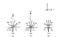
- the light 90a emitted from the central portion 110A, the light 91c emitted from the intermediate portion 110B, and the light 92c emitted from the peripheral portion 110C are observed.
- the viewpoint Q light 90a emitted from the central portion 110A, light 91a emitted from the intermediate portion 110B, and light 92a emitted from the peripheral portion 110C are observed.
- the viewpoint R light 90a emitted from the central portion 110A, light 91b emitted from the intermediate portion 110B, and light 92b emitted from the peripheral portion 110C are observed.
- the light 90 a, 91 a, and 92 a are peak components of light emitted from the light distribution control member 83.
- the light distribution control member 83 is used to convert the light having a narrow-angle light distribution distributed from the optical member 107 so that the light distribution becomes wide, and the direction of the peak component of the light is the liquid crystal display panel. By converting so as to face the normal passing through the central portion of the display surface 106b of 106, it is possible to reduce a decrease in luminance in the peripheral portion even when viewed from any viewpoint from infinity to a short distance.
- the concave surface 109 is displayed so that the direction of the peak component of the light emitted from the light distribution control member 83 is directed to the normal line passing through the center of the display surface 106b of the liquid crystal display panel 106. Since it is made to incline with respect to the normal line direction of the surface 106b, in addition to the effect of Embodiment 1, the luminance fall in a peripheral part can further be reduced.
- FIG. 11 shows a liquid crystal display device according to a fourth embodiment.
- FIG. 11 (a) is an enlarged cross-sectional view showing a central portion of the light distribution control member
- FIG. 11 (b) is a diagram of the light distribution control member. Sectional drawing which expands and shows an intermediate part
- FIG.11 (c) is sectional drawing which expands and shows the peripheral part of a light distribution control member.
- the concave surface 109 is used as the method of the display surface 106b so that the direction of the peak component of the light emitted from the light distribution control member 83 is directed to the normal passing through the center of the display surface 106b of the liquid crystal display panel 106.
- the concave surface 109 may be provided on the emission surface 83b, and the inclined surface 116 facing the concave surface 109 may be provided on the incident surface 83a. Even in this case, the direction of the peak component of the light emitted from the light distribution control member 83 can be directed to the center of the display surface 106 b of the liquid crystal display panel 106. In addition, since it is the same as that of Embodiment 3 except the shape of the light distribution control member 83, the description is abbreviate
- a concave surface 109 having a radius of curvature r2 is formed on the emission surface 83b in the peripheral portion 110C, and a straight line connecting the midpoint of the concave surface 109 and the center of curvature O4 thereof is parallel to the Z axis.
- the incident surface 83a is provided with an inclined surface 116 facing the concave surface 109.
- the inclined surface 116 is a light distribution control member with respect to the X axis and the Y axis which are parallel directions of the liquid crystal display panel 106. It is inclined by ⁇ 4 toward the periphery of 83.
- the radius of curvature r2 is smaller than r1 and the inclination angle ⁇ 4 is larger than ⁇ 3.
- the radius of curvature of the concave surface 109 including the other regions becomes smaller as it is located in the peripheral portion 110C.
- the slope of the inclined surface 116 is formed so as to increase as it is located in the peripheral portion 110C.
- the exit surface 83b is provided with the concave surface 109 having the curvature radius r1
- the incident surface 83a is formed with the inclined surface 116 inclined by ⁇ 3 with respect to the X axis and the Y axis.
- the emitted light having a narrow-angle light distribution is directed toward the normal line passing through the center of the display surface 106b of the liquid crystal display panel 106 by the inclined surface 116 of the incident surface 83a, and the concave surface 109 of the output surface 83b.
- the distribution is expanded in the Y-axis direction.
- the exit surface 83b is provided with a concave surface 109 having a curvature radius r2 smaller than the curvature radius r1, and the incident surface 83a is inclined with respect to the X axis and the Y axis by ⁇ 4 larger than the inclination angle ⁇ 3. Since the surface 116 is formed, the light having a narrow-angle light distribution radiated from the downward prism sheet 82 is inclined more than the intermediate portion 110B by the inclined surface 116 of the incident surface 83a, and by the concave surface 109 of the output surface 83b. It is wider than the intermediate portion 110B in the Y-axis direction.
- the light emitted from the light distribution control member 83 is gradually widened from the central part to the peripheral part of the liquid crystal display panel 106 while the light having the narrow-angle light distribution emitted from the optical member 107 is gradually increased.
- the direction of the peak component of the light is converted so as to face the normal line passing through the center of the display surface 106 b of the liquid crystal display panel 106, and is emitted from the light distribution control member 83.
- a plurality of concave surfaces 109 are provided on the emission surface 83b of the light distribution control member 83, and a plurality of inclined surfaces 116 facing the plurality of concave surfaces 109 are provided on the incident surface 83a. Since the inclined surface 116 is formed so that the direction of the peak component of the light emitted from the light distribution control member 83 is directed to the normal line passing through the center of the display surface 116b of the liquid crystal display panel 116, the same as in the third embodiment. An effect can be obtained.
- FIG. 12 to 14 show the liquid crystal display device according to the fifth embodiment.
- FIG. 12 is a diagram schematically showing the configuration of the liquid crystal display device.
- FIG. 13A is a light distribution control member in FIG.
- FIG. 13B is an enlarged cross-sectional view showing a peripheral portion of the light distribution control member in FIG. 12, and
- FIG. 14 is an angle formed by each surface of the optical surface and the XY plane. It is explanatory drawing at the time of calculating
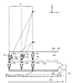
- the liquid crystal display device of the fifth embodiment includes a liquid crystal display panel 106, a light distribution control member 83, a downward prism sheet 82, a light guide plate 81, a light reflection sheet 80, and light sources 117A and 117B.
- the point is the same as that of the first embodiment, but the light distribution control member 83 of the first embodiment is provided with a plurality of concave surfaces 109, whereas the light distribution control member 83 of the fifth embodiment is different from the first embodiment.
- the optical surface 1000 has a first surface 103a, a second surface 103b, and a third surface 103c, as shown in FIGS. 13 (a) and 13 (b). These planes are planes inclined with respect to the X-axis and the Y-axis at different angles, respectively, and the direction of the peak component of light having a narrow-angle light distribution that is incident on the light distribution control member 83 is set to the first
- the surface 103a faces the short-distance viewpoint R
- the second surface 103b faces the medium-distance viewpoint Q
- the third surface 103c faces the infinity viewpoint P.
- the angles formed by the first surface 103a and the second surface 103b with respect to the Y axis are ⁇ 6 and ⁇ 5, respectively, and the third surface is It is parallel to the Y axis. Further, ⁇ 6 is larger than ⁇ 5.
- the angles formed by the first surface 103a and the second surface 103b with respect to the Y axis are ⁇ 8 and ⁇ 7, respectively, and the third surface is It is parallel to the Y axis. Also, ⁇ 8 is larger than ⁇ 7.
- the light emitted from the downward prism sheet 82 and emitted from the light distribution control member 83 through the third surface 103c has the direction of the light 94c and 95c, which are light peak components having a narrow angle light distribution, in the viewpoint P. Is consistent with the direction.
- the light emitted from the light distribution control member 103 via the second surface 103b corresponds to the inclinations ⁇ 5 and ⁇ 7 of the second surface 103b and has a light peak having a narrow-angle light distribution.
- the directions of the components of the light beams 94a and 95a change and coincide with the direction of the viewpoint Q.
- the light emitted from the light distribution control member 103 via the first surface 103a is a peak component of light having a narrow-angle light distribution corresponding to the inclinations ⁇ 6 and ⁇ 8 of the first surface 103a.
- the directions of the light 94b and 95b change and coincide with the direction of the viewpoint R.
- any viewpoint of P, Q, and R is obtained.
- a certain peripheral luminance can be secured.
- the peak component of the light emitted from the third surface 103c is also the viewpoint for the optical surfaces provided in other regions.
- the peak component of the light emitted from the second surface 103b is observed at the viewpoint Q
- the peak component of the light emitted from the first surface 103a is observed at the viewpoint R. Is formed.
- ⁇ can be determined by the same method for other surfaces.
- d is the distance along the Z axis from the incident point M of the light to the first surface 103a to the viewpoint X
- l is the distance along the Y axis from the incident point M to the viewpoint X
- tan ( ⁇ / 2 + ⁇ ′) d / l
- nsin ⁇ sin ⁇ ′ (2)
- n is the refractive index of the light distribution control member 83
- the refractive index of air is 1.
- Equations (1) and (2) If d, n, and l are determined by Equations (1) and (2), ⁇ at an arbitrary position can be obtained. That is, the inclination of each surface of the optical surface at an arbitrary position of the light distribution control member 83 can be obtained from an arbitrary viewpoint.
- the light distribution control member 83 has the first surface 103a, the second surface 103b, and the third surface 103c, and the narrow-angle light distribution emitted from the optical member 107. Since a plurality of optical surfaces 1000 that change the direction of the peak component of light having a distribution to face the directions of the viewpoints P, Q, and R are provided, a constant peripheral luminance is obtained at the viewpoints P, Q, and R. Can be secured.
- the uniformity of the in-plane luminance distribution of the backlight can be improved. it can.
- the backlight since the backlight is provided, it is possible to ensure a certain peripheral luminance at the viewpoints P, Q, and R.
- the width or arrangement interval (pitch) in the Y-axis direction of the adjacent optical surface 1000 in the light distribution control member 83 is increased, the light emission direction varies depending on the position of the display surface 106b of the liquid crystal display panel 106. In-plane luminance unevenness in the X-axis direction is observed at 106b. On the other hand, if the width and pitch are too small, processing becomes difficult and the light utilization efficiency of the light distribution control member 83 decreases.
- an image displayed on a liquid crystal display panel is formed by pixels which are basic display units.
- This pixel further includes RGB element pixels.
- the light intensity from each element pixel is adjusted by the liquid crystal display panel, and the light is synthesized by the human eye, whereby the color of the pixel is determined.
- the width and pitch of the optical surface 1000 in the Y-axis direction are larger than the RGB element pixels, the chromaticity or luminance of a certain pixel is observed differently from the chromaticity or luminance that should be displayed at a certain viewpoint. End up. Therefore, it is desirable that the width and pitch of each optical surface 1000 be configured to be smaller than the size of the element pixel in the Y-axis direction.
- the number of optical surfaces 1000 included in the size in the Y-axis direction of each RGB element pixel is approximately the same.
- the first surface 103a, the second surface 103b, and the third surface 103c of the optical surface 1000 have been described as flat surfaces.
- the present invention is not limited thereto, and may be curved surfaces or the like. .
- the surface is concave, as described in the first and second embodiments, the light distribution of the light emitted from each surface can be widened, so that a decrease in peripheral luminance can be reduced at a wider viewing distance.
- the viewpoint P is set to infinity and the third surface 103c is parallel to the XY plane.
- the third viewpoint is set to a position that is not infinity except for the central portion 110A.
- the surface 103c may be inclined with respect to the XY plane.
- an optical surface 1000 is shown in which each surface is provided in the order of the third surface 103c, the second surface 103b, and the first surface 103a from the central portion toward the peripheral portion.
- this order can be changed.
- optical surface 1000 is provided on the emission surface 83b side of the light distribution control member 83, it may be provided on the incident surface 83a side.
- light having a narrow-angle light distribution emitted from the optical member 107 is converted into a viewpoint P that is an infinite viewpoint, a viewpoint Q that is an intermediate distance viewpoint, and a viewpoint that is a short distance viewpoint.
- the light distribution control member 83 for conversion toward the three viewpoints of R is illustrated, the present invention is not limited to this, and the viewpoint can be set to 2 or more, and the viewing distance can be selected to an arbitrary value. is there.
- FIG. 15 is a diagram schematically showing a configuration of a liquid crystal display device (transmission type liquid crystal display device) 100 according to the sixth embodiment of the present invention.
- the liquid crystal display device 100 is obtained by applying the light distribution control member 83 of the first embodiment to a liquid crystal display device having a viewing angle variable function described later.
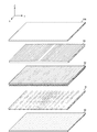
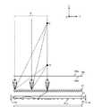
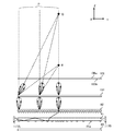
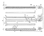
- FIG. 16 is a diagram schematically showing a configuration in which a part of the configuration of the liquid crystal display device 100 of FIG. 15 is viewed from the Y-axis direction. 15 and 16, the liquid crystal display device 100 includes a transmissive liquid crystal display panel 10, an optical sheet 9, a first backlight unit 1, a second backlight unit 2, a light reflecting sheet 8, and light distribution control.
- a member 83 is provided, and these components 10, 9, 1, 2, 8, and 83 are arranged along the Z-axis.
- the liquid crystal display panel 10 has a display surface 10a parallel to an XY plane including an X axis and a Y axis perpendicular to the Z axis.
- the X axis and the Y axis are orthogonal to each other.
- a liquid crystal display device excluding the light distribution control member 83 will be described.
- the liquid crystal display device 100 further includes a panel driving unit 102 for driving the liquid crystal display panel 10, a light source driving unit 103 A for driving the light sources 3 A and 3 B included in the first backlight unit 1, and the second backlight unit 2.
- a light source driving unit 103B for driving the included light sources 6A and 6B. The operations of the panel driving unit 102 and the light source driving units 103A and 103B are controlled by the control unit 101.
- the control unit 101 performs image processing on a video signal supplied from a signal source (not shown) to generate control signals, and supplies these control signals to the panel driving unit 102 and the light source driving units 103A and 103B.
- the light source driving units 103A and 103B drive the light sources 3A, 3B, 6A, and 6B in accordance with control signals from the control unit 101, and emit light from these light sources 3A, 3B, 6A, and 6B, respectively.
- the first backlight unit 1 determines the light emitted from the light sources 3A and 3B within a relatively narrow angle range centered on the normal direction of the display surface 10a of the liquid crystal display panel 10, that is, the Z-axis direction. It is converted into illumination light 11 having a distribution in which light of an intensity or higher is localized and emitted toward the back surface 10 b of the liquid crystal display panel 10. The illumination light 11 is applied to the back surface 10 b of the liquid crystal display panel 10 through the optical sheet 9.
- the optical sheet 9 suppresses optical influences such as fine illumination unevenness.
- the second backlight unit 2 has a wide-angle light distribution (the distribution in which light having a predetermined intensity or more is localized within a relatively wide angle range centering on the Z-axis direction) for the light emitted from the light sources 6A and 6B.
- the illumination light 12 is converted and emitted toward the back surface 10 b of the liquid crystal display panel 10.
- the illumination light 12 passes through the first backlight unit 1 and the optical sheet 9 and is irradiated on the back surface 10 b of the liquid crystal display panel 10.
- a light reflecting sheet 8 is disposed immediately below the second backlight unit 2. Of the light emitted from the first backlight unit 1 to the back side thereof, the light transmitted through the second backlight unit 2 and the light emitted from the second backlight unit 2 to the back side thereof are light reflecting sheets. 8 is used as illumination light that is reflected at 8 and irradiates the back surface 10 b of the liquid crystal display panel 10.
- the light reflecting sheet 8 for example, a light reflecting sheet based on a resin such as polyethylene terephthalate, or a light reflecting sheet obtained by depositing metal on the surface of the substrate can be used.
- the liquid crystal display panel 10 has a liquid crystal layer 10c extending along an XY plane orthogonal to the Z-axis direction.
- the display surface 10a of the liquid crystal display panel 10 has a rectangular shape, and the X-axis direction and the Y-axis direction shown in FIGS. 15 and 16 are directions along two mutually orthogonal sides of the display surface 10a.
- the panel drive unit 102 changes the light transmittance of the liquid crystal layer 10c in units of pixels in accordance with the control signal supplied from the control unit 101. As a result, the liquid crystal display panel 10 spatially modulates the illumination light incident from one or both of the first backlight unit 1 and the second backlight unit 2 to generate image light, and this image light is displayed on the display surface. 10a can be emitted.
- the illumination light 11 having a narrow-angle light distribution is emitted from the first backlight unit 1, so that the viewing angle of the liquid crystal display device 100 is
- the illumination light 12 having a wide-angle light distribution is emitted from the second backlight unit 2, so that the viewing angle of the liquid crystal display device 100 is a wide viewing angle. It becomes.
- the control unit 101 individually controls the light source driving units 103 ⁇ / b> A and 103 ⁇ / b> B, and the intensity of the illumination light 11 emitted from the first backlight unit 1 and the illumination light 12 emitted from the second backlight unit 2. The ratio with the intensity can be adjusted.
- the first backlight unit 1 includes light sources 3A and 3B, a light guide plate 4 arranged in parallel to the display surface 10a of the liquid crystal display panel 10, and an optical sheet 5D (hereinafter referred to as a downward direction). Prism sheet 5D) and optical sheet 5V (hereinafter referred to as upward prism sheet 5V).
- the light guide plate 4 and the downward prism sheet 5D first optical member
- the light emitted from the light sources 3A and 3B is converted into illumination light 11 having a narrow-angle light distribution.
- the light guide plate 4 is a plate-like member formed of a transparent optical material such as acrylic resin (PMMA), and the back surface 4a (the surface opposite to the liquid crystal display panel 10) is opposite to the liquid crystal display panel 10 side. , 40 projecting in a regular manner along the surface parallel to the display surface 10a.
- the shape of the micro optical element 40 is a part of a spherical shape, and its surface has a certain curvature.
- the upward prism sheet 5 ⁇ / b> V has an optical structure that transmits the illumination light 12 having a wide-angle light distribution distributed by the second backlight unit 2, and further reflects the light emitted from the back surface 4 a of the light guide plate 4.
- the optical structure is returned to the direction of the light guide plate 4.
- the light radiated from the back surface 4a of the light guide plate 4 is reflected by the upward prism sheet 5V, changes its traveling direction to the direction of the liquid crystal display panel 10, and passes through the light guide plate 4 and the downward prism sheet 5D, thereby narrowing the angle. Used as illumination light with a light distribution.
- the light sources 3A and 3B are respectively disposed opposite to both end faces (incident end faces) 4c and 4d in the Y-axis direction of the light guide plate 4, and for example, a plurality of laser light emitting elements are arranged in the X-axis direction.
- Light emitted from these light sources 3A and 3B is incident on the light guide plate 4 from the incident end faces 4c and 4d of the light guide plate 4, and propagates through the light guide plate 4 while being totally reflected. At that time, part of the propagation light is reflected by the micro optical element 40 on the back surface 4a of the light guide plate 4, and is emitted from the front surface (light exit surface) 4b of the light guide plate 4 as illumination light 11a.
- the micro optical element 40 converts light propagating inside the light guide plate 4 into light having a light distribution distribution centered on a direction inclined by a predetermined angle from the Z-axis direction and radiates it from the front surface 4b.
- the light 11a radiated from the light guide plate 4 is incident on the inside of the micro optical element 50 of the downward prism sheet 5D, is totally internally reflected by the inclined surface of the micro optical element 50, and then from the front surface (light exit surface) 5b. Radiated as illumination light 11.
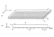
- FIGS. 17A and 17B are diagrams schematically showing an example of the optical structure of the light guide plate 4.
- 17A is a perspective view schematically showing an example of the structure of the back surface 4a of the light guide plate 4.
- FIG. 17B is a view from the X-axis direction of the light guide plate 4 shown in FIG. It is a figure which shows a part of structure seen.
- convex spherical micro optical elements 40 are two-dimensionally arranged along the XY plane on the back surface 4a of the light guide plate 4.
- FIG. 17A convex spherical micro optical elements 40 are two-dimensionally arranged along the XY plane on the back surface 4a of the light guide plate 4.
- the micro optical element 40 for example, a micro optical element having a surface curvature of about 0.15 mm, a maximum height Hmax of about 0.005 mm, and a refractive index of about 1.49 can be employed.
- the center distance Lp between the micro optical elements 40 and 40 can be set to 0.077 mm.
- the material of the light-guide plate 4 can be made from an acrylic resin, it is not limited to this material. As long as the material has good light transmittance and excellent moldability, other resin materials such as polycarbonate resin or glass material may be used instead of acrylic resin.
- the light emitted from the light sources 3A and 3B is incident on the inside of the light guide plate 4 from the side end surfaces 4c and 4d of the light guide plate 4.
- the incident light propagates through the inside of the light guide plate 4 and is totally reflected by the difference in refractive index between the micro optical element 40 of the light guide plate 4 and the air layer, and travels from the front surface 4 b of the light guide plate 4 toward the liquid crystal display panel 10. Radiated.
- the micro optical elements 40,..., 40 shown in FIGS. 17A and 17B are substantially regularly arranged on the back surface 4a of the light guide plate 4, but are emitted from the front surface 4b of the light guide plate 4.
- the density of the fine optical elements 40 that is, the number per unit area is increased as the distance from the end faces 4c and 4d increases. The closer you are, the fewer you may be.
- the fine optical elements 40,..., 40 may be formed so as to be denser as they are closer to the center of the light guide plate 4, and gradually become sparser as they move away from the center.
- FIG. 18 is a graph showing a calculation result by simulation of the light distribution (angular luminance distribution) of the radiated light 11 a emitted from the front surface 4 b of the light guide plate 4.
- the horizontal axis represents the radiation angle of the emitted light 11a
- the vertical axis represents the luminance.
- the light distribution of the emitted light 11a has a distribution width (full width at half maximum: FWHM) of about 30 degrees around an axis inclined about ⁇ 75 degrees from the Z-axis direction.
- the light distribution of the radiated light 11a is about an angle range of about +60 degrees to +90 degrees around an axis inclined about +75 degrees from the Z-axis direction and about an axis inclined about -75 degrees from the Z-axis direction.
- This is a distribution in which light having an intensity greater than the full width at half maximum is localized in an angular range of ⁇ 60 degrees to ⁇ 90 degrees.
- the light emitted from the light source 3B on the right side of FIG. 15 is internally reflected by the micro optical element 40 to form radiated light mainly in an angle range of ⁇ 60 degrees to ⁇ 90 degrees.
- the light emitted from the light source 3A is internally reflected by the fine optical element 40 to form radiated light mainly in an angular range of +60 degrees to +90 degrees.
- the shape of the micro optical element 40 is changed to a prism shape instead of the convex spherical shape, the emitted light having such a light distribution can be generated.
- the radiation light 11a incident on the inside of the micro optical element 50 of the downward prism sheet 5D is totally reflected by the inner surface of the micro optical element 50.
- the light that has undergone total reflection on the inner surface of the micro optical element 50 is localized in a narrow angle range centered on the Z-axis direction, and forms illumination light 11 having a narrow-angle light distribution.
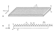
- FIGS. 19A and 19B are diagrams schematically showing an example of the optical structure of the downward prism sheet 5D.
- FIG. 19A is a perspective view schematically showing an example of the structure of the back surface 5a of the downward prism sheet 5D
- FIG. 19B is the X axis of the downward prism sheet 5D shown in FIG. 19A. It is a figure which shows schematically a part of structure seen from the direction.
- the back surface 5a of the downward prism sheet 5D (that is, the surface facing the light guide plate 4) is arranged in the Y-axis direction along a surface in which the plurality of micro optical elements 50 are parallel to the display surface 10a.
- Each micro optical element 50 forms a triangular prism-shaped convex portion, the apex angle portion of the micro optical element 50 protrudes on the opposite side to the liquid crystal display panel 10 side, and the ridge line forming the apex angle portion is in the X-axis direction It extends to.
- the interval between the micro optical elements 50 and 50 is constant.
- Each micro optical element 50 has two inclined surfaces 50a and 50b inclined from the Z-axis direction to the + Y-axis direction and the -Y-axis direction, respectively.
- the incident light is bent so as to approach the normal direction (Z-axis direction) of the liquid crystal display panel 10 by total internal reflection at one of the inclined surfaces 50a and 50b forming the triangular prism of the micro optical element 50.
- the illumination light 11 has a light distribution with a high center luminance and a narrow distribution width.
- the apex angle formed by the inclined surfaces 50a and 50b is 68 degrees and the height Tmax. Is a fine optical element having a refractive index of 1.49.
- the micro optical elements 50,..., 50 can be arranged so that the center interval Wp in the Y-axis direction is 0.03 mm.
- the material of the downward prism sheet 5D can be PMMA, but is not limited to this material. Other resin materials such as polycarbonate resin or glass material may be used as long as the material has good light transmittance and excellent moldability.
- FIG. 20 is a graph showing a calculation result by simulation of the light distribution of the illumination light 11 emitted from the front surface 5b of the downward prism sheet 5D.
- the horizontal axis represents the radiation angle of the illumination light 11
- the vertical axis represents the luminance. Note that the light distribution shown in FIG. 20 does not include light emitted from the second backlight unit 2 and transmitted through the first backlight unit 1.
- the light distribution of the illumination light 11 has a distribution width (full width at half maximum: FWHM) having a radiation angle of about 30 degrees centered in the Z-axis direction.
- the light distribution of the illumination light 11 is a narrow-angle light distribution in which light having an intensity greater than or equal to the full width at half maximum is localized within an angular range of ⁇ 15 degrees to +15 degrees with the Z-axis direction as the center.
- the narrow-angle light distribution shown in FIG. 20 is based on the premise that the emitted light 11a from the light guide plate 4 has the light distribution shown in FIG.
- the light distribution in FIG. 18 is (1) premised on the use of light sources 3A and 3B having a Lambertian angular intensity distribution, and (2) the radiated light 11a from the light guide plate 4 is a micro optical element of the downward prism sheet 5D.
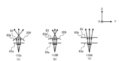
- FIGS. 21A and 21B are diagrams schematically showing an optical action of the micro optical element 50.
- the micro optical element 50 has a light beam IL (mainly reflected by the micro optical element 40 of the light guide plate 4 to be internally reflected) incident on the inclined surface 50a at a predetermined angle or more with respect to the Z-axis direction.
- the radiated light 11a) is totally reflected by the inclined surface 50b.
- the outgoing angle of the outgoing light beam OL becomes smaller than the incident angle of the incoming light beam IL.
- FIG. 21 (a) the micro optical element 50 has a light beam IL (mainly reflected by the micro optical element 40 of the light guide plate 4 to be internally reflected) incident on the inclined surface 50a at a predetermined angle or more with respect to the Z-axis direction.
- the radiated light 11a) is totally reflected by the inclined surface 50b.
- the outgoing angle of the outgoing light beam OL becomes smaller than the incident angle of the incoming light beam IL.
- the micro optical element 50 has a light beam IL (mainly a light guide in the second backlight unit 2) incident on the inclined surface 50a at a angle less than a predetermined angle with respect to the Z-axis direction.
- the illumination light 12) radiated from the front surface 7b of the light plate 7 and transmitted through the light guide plate 4 is refracted and radiated in an angle direction greatly inclined from the Z-axis direction.
- the outgoing angle of the outgoing light beam OL becomes larger than the incident angle of the incident light beam IL.
- the downward prism sheet 5D has a light distribution distribution when light having a light distribution distribution in which light of a predetermined intensity or more is localized within a relatively wide angle range centering on the Z-axis direction incident from the back surface 5a.
- the light can be emitted from the front surface 5b without almost narrowing the distribution. Therefore, even if the illumination light 12 emitted from the front surface 7b of the light guide plate 7 passes through the upward prism sheet 5V, the light guide plate 4, and the downward prism sheet 5D, it is not narrowed.
- FIGS. 22A and 22B are diagrams schematically showing an example of the optical structure of the upward prism sheet 5V.
- FIG. 22A is a perspective view schematically showing an example of the structure of the surface 5c of the upward prism sheet 5V
- FIG. 22B is a Y-axis of the upward prism sheet 5V shown in FIG. It is a figure which shows schematically a part of structure seen from the direction.
- the surface 5c of the upward prism sheet 5V (surface facing the light guide plate 4) has a plurality of micro optical elements 51,... 51 along a surface parallel to the display surface 10a. It has a structure regularly arranged in the X-axis direction.
- Each micro optical element 51 forms a triangular prism-shaped convex portion, the apex angle portion of the micro optical element 51 protrudes toward the liquid crystal display panel 10, and the ridge line forming the apex angle portion extends in the Y-axis direction. ing.
- the interval between the micro optical elements 51 and 51 is constant.
- Each micro optical element 51 has two inclined surfaces 51a and 51b that are inclined from the Z-axis direction to the + X-axis direction and the ⁇ X-axis direction, respectively.
- the arrangement direction (X-axis direction) of the fine optical elements 51,... 51 of the upward prism sheet 5V is substantially orthogonal to the arrangement direction (Y-axis direction) of the fine optical elements 50,. .
- the apex angle formed by the inclined surfaces 51a and 51b (vertical angle of a right isosceles triangle shape in the cross section of FIG. 22B) is used. It is possible to employ a microstructure element having 90 degrees, a maximum height Dmax of 0.015 mm, and a refractive index of 1.49. Further, the micro optical elements 51,..., 51 can be arranged so that the center interval Gp in the X-axis direction is 0.03 mm.
- the material of the prism sheet can be PMMA, but is not limited to this material. Other resin materials such as polycarbonate resin or glass material may be used as long as the material has good light transmittance and excellent moldability.
- the upward prism sheet 5V causes the back surface 5e to totally reflect light (return light) incident on the micro optical elements 51,... 51 from the light guide plate 4 so that the traveling direction of the return light is the direction of the liquid crystal display panel 10. Can be changed.
- the return light from the light guide plate 4 includes light radiated in the direction opposite to the liquid crystal display panel 10 side without satisfying the total reflection condition on the back surface 4a of the light guide plate 4, and the liquid crystal display panel from the downward prism sheet 5D.
- emitted on the opposite side to 10 side is mentioned. Since the upward prism sheet 5V can use such return light as illumination light of the first backlight unit 1 again, the light use efficiency can be improved.
- FIGS. 23A and 23B are diagrams schematically showing an optical action of the fine optical element 51 of the upward prism sheet 5V.
- the arrangement direction (X-axis direction) of the micro optical elements 51,..., 51 of the present embodiment is substantially the same as the arrangement direction (Y-axis direction) of the micro optical elements 50,.
- FIG. 23A is a diagram schematically showing a partial cross section parallel to the XZ plane of the upward prism sheet 5V having the micro optical elements 51, 51, 51, and
- FIG. 6A is a partial cross-sectional view of the upward prism sheet 5V taken along line IXb-IXb.
- FIG. 24A is a diagram schematically showing a partial cross section parallel to the YZ plane of the upward prism sheet 5V
- FIG. 24B is an Xb ⁇ diagram of the upward prism sheet 5V in FIG. It is a fragmentary sectional view along line Xb.
- FIG. 24A and 24B show the behavior of light when the return light RL is incident from the light guide plate 4 into the micro optical element 51.
- FIG. Here, of the actual return light from the light guide plate 4, the behavior of the light propagating along the YZ plane is dominant, and therefore, for the sake of convenience of explanation, the return propagating on the plane parallel to the YZ plane. Only the light RL is shown in a simplified manner.
- each micro optical element 51 has a pair of inclined surfaces 51a and 51b having an inclination angle symmetrical with respect to the Z-axis direction in the XZ plane.
- the light beam as the return light RL enters the inclined surface 51a of the micro optical element 51 at various incident angles. Then, as shown in FIG. 23A, the light incident along the Z-axis direction is refracted by the inclined surface 51a in the ⁇ X-axis direction.
- the return light RL also enters the inclined surface 51b of the micro optical element 51, and is refracted in the + X-axis direction by the inclined surface 51b.
- the incident angle of the refracted light traveling in the upward prism sheet 5V to the back surface 5e is large, and refracted light that satisfies the total reflection condition tends to occur at the interface (back surface 5e) between the upward prism sheet 5V and the air layer.
- the incident angle of the refracted light on the back surface 5e tends to be greater than the critical angle.
- the light OL totally reflected from the inner surface by the back surface 5e is emitted in the direction of the liquid crystal display panel 10 as shown in FIGS.
- the upward prism sheet 5V has an optical structure in which pairs of inclined surfaces 51a and 51b of the micro optical element 50 are continuously arranged along the X-axis direction.
- the structure of the upward prism sheet 5V is symmetric with respect to the Z-axis direction in the YZ plane. Therefore, when the refracted light traveling in the upward prism sheet 5V is totally reflected on the inner surface by the back surface 5e, the return light RL to the upward prism sheet 5V is reflected in both the XZ plane and the YZ plane.
- the light is emitted from the upward prism sheet 5V toward the liquid crystal display panel 10 at an angle substantially equal to the incident angle (incident angle with respect to the Z-axis direction). Further, as shown in FIG. 23 (b), the light having a small incident angle (incident angle with respect to the Z-axis direction) to the upward prism sheet 5V in the return light RL is not totally reflected on the inner surface by the back surface 5e. Relatively large light is totally reflected from the inner surface by the back surface 5e, thereby being converted into outgoing light OL. Therefore, a part of the light distribution of the return light RL is preserved, and the traveling direction of a part of the return light RL is changed to the direction of the liquid crystal display panel 10.
- the emitted light OL is transmitted through the light guide plate 4 so that the inner surface is totally reflected by the micro optical element 50 of the downward prism sheet 5D and converted into the illumination light 11 having a narrow angle light distribution.
- Distribution for example, as shown in FIG. 18, an angle range of about +60 degrees to +90 degrees around an axis inclined about +75 degrees from the Z-axis direction and an axis inclined about -75 degrees from the Z-axis direction.
- the light is converted into light having a distribution in which light having an intensity greater than the full width at half maximum is localized in an angular range of about ⁇ 60 degrees to ⁇ 90 degrees.
- the light emitted from the upward prism sheet 5V in the direction of the liquid crystal display panel 10 in this way passes through the light guide plate 4 and enters the downward prism sheet 5D, whereby the light distribution has a high central luminance and a narrow distribution width.
- the illumination light 11 having a distribution is converted to illuminate the back surface 10 b of the liquid crystal display panel 10.
- the ratio of the light amount of the illumination light 11 having a narrow-angle light distribution radiated from the first backlight unit 1 to the light amount radiated from the light sources 3A and 3B constituting the first backlight unit 1 (this , Defined as the light use efficiency of the first backlight unit 1). Therefore, the amount of light source required to ensure the predetermined luminance on the display surface 10a can be reduced compared to the conventional case, and the power consumption of the liquid crystal display device 100 can be suppressed.
- the traveling direction of the light in the micro optical element 51 is , Complicated by refraction and reflection.
- the light that does not satisfy the total reflection condition on the back surface 5e of the upward prism sheet 5V increases and is emitted from the back surface 5e of the upward prism sheet 5V to the side opposite to the liquid crystal display panel 10. More light. Therefore, the amount of light that is totally reflected by the upward prism sheet 5V and radiated toward the liquid crystal display panel 10 is reduced. Therefore, from the viewpoint of obtaining a high power consumption reduction effect, the arrangement direction of the micro optical elements 51,..., 51 of the upward prism sheet 5V is substantially orthogonal to the arrangement direction of the micro optical elements 50,. It is preferable.
- the liquid crystal display device 100 has a configuration in which a first backlight unit 1 and a second backlight unit 2 are stacked.
- the first backlight unit 1 includes a second backlight unit 2 and a liquid crystal. It is provided between the display panel 10. Since the first backlight unit 1 needs to transmit the illumination light 12 having a wide-angle light distribution distributed from the second backlight unit 2, the first backlight unit 1 transmits the return light RL to the liquid crystal display panel.
- a light reflecting sheet having a low light transmittance and a high reflectance like the light reflecting sheet 8.
- the first backlight unit 1 does not use this type of light reflecting sheet, and has the upward prism sheet 5V having a very high light transmittance, and therefore is emitted from the light sources 6A and 6B constituting the second backlight unit.
- the ratio of the amount of light having a wide-angle light distribution radiated from the display surface 10a of the liquid crystal display device 100 to the amount of light (this is defined as the light use efficiency of the second backlight unit 2) is not reduced. , Increase in power consumption can be suppressed.
- the light reflecting sheet 8 reflects the return light propagated from the first backlight unit 1 and the second backlight unit 2 in the direction of the liquid crystal display panel 10 to be reused as illumination light.
- the light incident on the surface of the light reflection sheet 8 is light having a wide-angle light distribution distributed by the diffuse reflection structure 70 of the second backlight unit 2, and the liquid crystal display panel is formed on the surface of the light reflection sheet 8.
- the light reflected in the direction 10 is diffused when reflected by the surface of the light reflecting sheet 8 or when transmitted through the diffuse reflection structure 70. Therefore, in the light incident on the first backlight unit 1 from the back side, the proportion of light having an angle required to be converted into the illumination light 11 having a narrow-angle light distribution is reduced. .
- the upward prism sheet 5V is necessary for the incident light to the downward prism sheet 5D to be totally reflected on the inner surface by the fine optical element 50 and converted to the illumination light 11 having a narrow angle light distribution. It is possible to emit light having a light distribution. Therefore, the upward prism sheet 5V efficiently converts the return light RL incident from the light guide plate 4 into light having a narrow-angle light distribution around the normal direction of the display surface 10a of the liquid crystal display panel 10, The light utilization efficiency of the first backlight unit 1 can be improved.
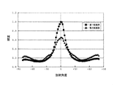
- FIG. 25 and FIG. 26 are graphs showing the results of experimentally measuring the angular luminance distribution (light distribution) of the light emitted from the backlight units having different structures.
- the horizontal axis represents the radiation angle of the emitted light
- the vertical axis represents the normalized luminance.
- FIG. 25 shows a light distribution of light emitted from the example (first example) of the first backlight unit 1 of the present embodiment in the direction of the liquid crystal display panel 10, and the micro optical elements 51,.
- the backlight unit of the second embodiment is configured.
- FIG. 26 instead of the upward prism sheet 5V in the first backlight unit 1 of the present embodiment, a light reflecting sheet having the same structure as the light reflecting sheet 8 is arranged, and the backlight unit of the first comparative example.
- the backlight unit of the second comparative example is configured by arranging the above, the distribution of light emitted from the backlight unit in the direction of the liquid crystal display panel 10 is shown.
- the amount of emitted light is larger than that of the second embodiment, and the light use efficiency for generating illumination light with a narrow-angle light distribution is high.
- the light distribution of the radiated light in the first and second embodiments it is within an angle range of 30 degrees centered on 0 degree (an angular range of ⁇ 15 degrees to +15 degrees). (Inside) the brightness is sufficiently localized.
- the light distribution of the first comparative example has a luminance distribution of about 0.4 or more in a range of less than ⁇ 30 degrees and a range of more than +30 degrees. Therefore, the light distribution is not narrow.
- the maximum peak luminance of the light distribution of the emitted light of the second comparative example is only about 0.5.
- the second backlight unit 2 is substantially parallel to the light sources 6A and 6B configured similarly to the light sources 3A and 3B of the first backlight unit 1 and the back surface 4a of the light guide plate 4 and And a light guide plate 7 disposed to face the back surface 4a.
- the light guide plate 7 is a plate-like member formed of a transparent optical material such as PMMA, and has a diffuse reflection structure 70 on the back surface 7a.
- the light sources 6A and 6B are disposed opposite to both end faces (incident end faces) 7c and 7d of the light guide plate 7 in the Y-axis direction.
- the light emitted from the light sources 6 ⁇ / b> A and 6 ⁇ / b> B enters the light guide plate 7 from the incident end faces 7 c and 7 d of the light guide plate 7.
- the incident light propagates while being totally reflected inside the light guide plate 7, and a part of the propagated light is diffusely reflected by the diffuse reflection structure 70 on the back surface 7 a and is emitted from the front surface 7 b of the light guide plate 7 as illumination light 12.
- the diffuse reflection structure 70 can be configured, for example, by applying a diffuse reflection material to the back surface 7a. Since the diffuse reflection structure 70 diffuses the propagation light over a wide angular range, the illumination light 12 emitted from the second backlight unit 2 is emitted toward the liquid crystal display panel 10 as illumination light having a wide-angle light distribution. .
- the liquid crystal display device 100 having the above configuration can not only make the light distribution of illumination light to the back surface 10b of the liquid crystal display panel 10 a narrow-angle light distribution or a wide-angle light distribution, but also a narrow-angle light distribution. And a light distribution distribution intermediate between the wide-angle light distribution.
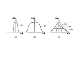
- 27A, 27B, and 27C are diagrams schematically illustrating three types of light distributions of illumination light. When the light sources 3A and 3B of the first backlight unit 1 are turned on and the light sources 6A and 6B of the second backlight unit 2 are not turned on, the back surface 10b of the liquid crystal display panel 10 is narrow as shown in FIG. Illuminated with illumination light having an angular light distribution D3.
- the observer can visually recognize a bright image from the front direction of the liquid crystal display device 100, but when viewing the display surface 10a from an oblique direction, the observer will visually recognize a dark image.
- the liquid crystal display device 100 does not emit light in an unnecessary direction other than the observation direction, the amount of light emitted from the light sources 3A and 3B can be reduced, and power consumption can be reduced.
- the back surface of the liquid crystal display panel 10 is as shown in FIG. Illuminated with illumination light 12 having a wide-angle light distribution D4. Therefore, an observer can visually recognize a bright image from a wide angle direction, and in order to ensure sufficient brightness in all the angle directions, the light sources 6A and 6B require a large light emission amount, Power consumption also increases.
- the control unit 101 controls the light emission amounts of the light sources 3A and 3B of the first backlight unit 1 and the light sources 6A and 6B of the second backlight unit 2 according to the observation direction. Control the amount of light emitted. For example, as illustrated in FIG. 27C, the control unit 101 generates the illumination light 12 of the first backlight unit 1 and the illumination light 11 of the second backlight unit 2, and the light distribution of the illumination light 12. By superimposing D3a and the light distribution D4a of the illumination light 11, an intermediate light distribution D5 is formed. As a result, an optimal light distribution D5 corresponding to the observation direction is obtained.
- the total light emission amount of the light sources 3A, 3B, 6A, and 6B as compared with the case of emitting illumination light with a wide-angle light distribution D4 so that a bright image can be viewed from a wide observation direction (FIG. 27B). Therefore, a large power consumption reduction effect can be obtained.
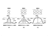
- FIGS. 28A to 28C are diagrams schematically showing an example of three types of viewing angle control.
- the viewing angle control is performed based on the relationship with the position of the observer.
- the control unit 101 sets the light emission amount of the first backlight unit 1 to the second backlight unit 2.
- the light distribution distribution D3aa by the first backlight unit 1 and the light distribution distribution D4aa by the second backlight unit 2 are overlapped to form a narrow-angle light distribution D5aa.
- Generate narrow viewing angle display mode
- the control unit 101 responds to the spread by the second backlight unit with respect to the light emission amount of the first backlight unit 1.
- the light distribution D3ab by the first backlight unit 1 and the light distribution D4ab by the second backlight unit 2 are overlapped to generate a wide angle light distribution D5ab.
- the control unit 101 emits light from the second backlight unit 2 with respect to the light emission amount of the first backlight unit 1 according to the spread.
- the control unit 101 sets the ratio of the light emission amount of the second backlight unit 2 to the light emission amount of the first backlight unit 1 in accordance with the spread as the position of the observer spreads left and right. Therefore, fine viewing angle control can be performed. Further, a higher power consumption reduction effect can be obtained.
- the control unit 101 controls the light emission amount of the light sources 3A, 3B, 6A, and 6B to control the liquid crystal display panel 10.
- the brightness (luminance) in the front direction of the liquid crystal display panel 10 can be controlled to always maintain a constant value L.
- the light sources 3A, 3, 6A, and 6B are light sources of the same light emission method.
- the reason is that when the viewing angle is changed by changing the ratio of the light emission amount of the first backlight unit 1 and the light emission amount of the second backlight unit 2, the light emission characteristics (light emission spectrum) of the light sources 3A, 3B, 6A, 6B are changed. This is because it is possible to avoid the possibility that the difference in the above causes a change in emission color.
- the same light source of the light emission method in the first backlight unit 1 and the second backlight unit 2 such a possibility can be avoided and good image quality can be maintained when the viewing angle is changed.
- a light source of the same light emission method for example, a light emitter having the same structure, a light emitter having the same light emission characteristics such as a light emission wavelength region, a light emitter module having the same combination of a plurality of light emitters having different light emission characteristics, or A light emitter driven by the same driving method can be given.
- the peripheral luminance decreases with the change of the viewpoint. Therefore, in the liquid crystal display device 100, the light distribution control member 83 of the first embodiment is disposed between the backlight unit 1 and the liquid crystal display panel 10. Thereby, in a liquid crystal display device having a function of changing the viewing angle, it is possible to reduce deterioration of peripheral luminance due to a change in viewing distance even when the viewing angle is narrowed.
- the micro optical element 40 has a convex spherical shape, but is not limited thereto. If the fine optical element 50 of the downward-facing prism sheet 5D has a structure that emits radiant light 11a that generates total internal reflection and generates illumination light 11 with a narrow-angle light distribution, a structure that replaces the fine optical element 40 is adopted. May be.
- the liquid crystal display device 100 according to the sixth embodiment has the light emission amount of the first backlight unit 1 and the light emission amount of the second backlight unit 2 without using complicated and expensive active optical elements.
- the viewing angle can be controlled by adjusting the ratio. Therefore, the liquid crystal display device 100 can minimize the amount of light emitted from the display surface 10a in an unnecessary direction, thereby realizing a viewing angle control function effective for reducing power consumption.
- the liquid crystal display device 100 according to the sixth embodiment has a simple and inexpensive configuration, and is an effective configuration from a small size to a large size regardless of the screen size. Further, since the liquid crystal display device 100 can accurately and easily control the light emission amount and the light emission direction of the first backlight unit 1 and the second backlight unit 2, it is optimally finely controlled without causing a color change of the display image. The viewing angle can be changed.
- the illumination light 11 having a narrow-angle light distribution can be generated by using the light guide plate 4 and the downward prism sheet 5D of the first backlight unit 1 without using an active optical element.
- the fine optical element 50 formed on the back surface 5a of the downward-facing prism sheet 5D causes the radiated light 11a incident from the front surface 4b of the light guide plate 4 to be totally reflected by the inclined surfaces 50a and 50b, thereby narrow-angle distribution.
- Illumination light 11 having a light distribution can be generated.
- the first backlight unit 1 since the first backlight unit 1 has the upward prism sheet 5V, the radiated light from the second backlight unit 2 is lost also in the backlight laminated liquid crystal display device 100 as in the present embodiment. Therefore, the light use efficiency of the first backlight unit 1 can be improved.
- the return light RL radiated from the light guide plate 4 of the first backlight unit 1 in the back direction is refracted by the micro optical element 51 of the upward prism sheet 5V and then the direction of the liquid crystal display panel 10 on the back surface 5e.
- the illumination light 11 of the first backlight unit 1 can be obtained.
- the illumination light 12 emitted from the second backlight unit 2 is not narrowed in the light distribution by the inclined surfaces 50a and 50b of the micro optical element 50 protruding to the back side, and the liquid crystal display panel 10 The back of the can be illuminated.
- a planar light source that emits illumination light having a wide-angle light distribution and an optical structure that condenses the illumination light and converts it into illumination light with a narrow-angle light distribution (for example, its In this configuration, the light emitted from the planar light source is converted into light with a narrow-angle light distribution. Therefore, the light distribution is narrowed even for the illumination light having a wide-angle light distribution radiated from the second backlight unit 2.
- the micro optical element 50 of the present embodiment does not collect the illumination light 12 from the second backlight unit 2 and does not narrow the wide-angle light distribution. For this reason, the structure of this embodiment can perform fine viewing angle control even when applied to a liquid crystal display device formed by laminating two or more layers of backlight units.
- the light sources 3A and 3B are provided on the side of the light guide plate 4, and the light sources 6A and 6B are provided on the side of the light guide plate 7, so that two or more layers are provided.
- a liquid crystal display device is configured by stacking a plurality of backlight units, a thin configuration with a small thickness in the Z-axis direction can be realized. Therefore, a thin liquid crystal display device having a viewing angle control function can be realized.
- control unit 101 controls the light emission amounts of the plurality of first backlight units 1 and second backlight units 2 while maintaining the luminance in the front direction of the display surface 10a at a predetermined instruction value L. Since the control is performed individually, it is possible to obtain an optimal distribution of illumination light according to the observation direction without bringing about unnecessary brightness. Furthermore, power consumption can be significantly reduced by minimizing light emitted in unnecessary directions.
- the light emission amounts of the light sources 3A, 3B, 6A, and 6B can be freely controlled.
- the light sources 3A, 3B, 6A, and 6B be solid light sources that can easily control the amount of emitted light, such as laser light sources or light emitting diodes. Thereby, more optimal viewing angle control can be performed.
- the light distribution control member of the first embodiment is used as the light distribution control member 83, but the present invention is not limited to this configuration. Any of the light distribution control members according to the second to fifth embodiments or the modifications thereof can be applied.
- the liquid crystal display device 200 is further included in the panel drive unit 202 that drives the liquid crystal display panel 10, the light source drive unit 203 ⁇ / b> A that drives the light source 3 ⁇ / b> C included in the first backlight unit 16, and the second backlight unit 17. And a light source driving unit 203B for driving the light sources 19,.
- the operations of the panel driving unit 202 and the light source driving units 203A and 203B are controlled by the control unit 201.
- the upward prism sheet 5V in the fourth and fifth embodiments has a structure for condensing the light of the second backlight unit 2 in a direction perpendicular to the direction in which the viewing angle is controlled. As a result, it is possible to narrow the light distribution in a direction that does not require a wide viewing angle, and obtain an effect of improving luminance or reducing power consumption.
- the light distribution control member 83 that receives light having a narrow-angle light distribution distributed from the optical member 107 and emits it in the direction of the liquid crystal display panel 106 is provided. Since the member 83 is provided with a plurality of convex surfaces 209 and the curvature radii of the plurality of convex surfaces 209 are formed so as to be closer to the peripheral portion 110C side of the light distribution control member 83, light having a narrow-angle light distribution can be obtained.
- the liquid crystal display panel 106 is converted so that it gradually becomes wider from the central part toward the peripheral part, and the luminance reduction in the peripheral part can be reduced regardless of the viewpoint from infinity to a short distance.
- the concave surface in the light distribution control member 83 in order to manufacture the concave surface by molding, it is necessary to process the mold into a convex surface.
- the convex surface is formed by molding. In order to manufacture, it is necessary to process the mold into a concave surface. Since it is more difficult to process a mold with a convex surface than with a concave surface, in Embodiment 8, the light distribution control member 83 can be manufactured more easily than when a concave surface is provided. It should be noted that the convex surface can be provided more easily by using an ink jet method utilizing the surface tension of the resin.
- the exit surface 83b of the central portion 110A in FIG. 32A has a planar shape, whereas the intermediate portion 110B in FIG. 32B and the exit surface 83b of the peripheral portion 110C in FIG. 209 is formed.
- the convex surface 209 in the intermediate portion 110B has a radius of curvature r3, and is inclined toward the peripheral portion of the light distribution control member by ⁇ 9 with respect to the Z axis that is the normal direction of the display surface 106b. That is, the straight line connecting the midpoint of the convex surface 209 and the center of curvature O5 forms an angle ⁇ 9 with the Z axis.
- the convex surface 209 in the peripheral portion 110C has a radius of curvature r4, and is inclined toward the peripheral portion of the light distribution control member by ⁇ 10 with respect to the Z axis. That is, the straight line connecting the midpoint of the convex surface 209 and its center of curvature O6 forms an angle ⁇ 10 with the Z axis.
- the curvature radius r4 is smaller than r3, and the inclination accuracy ⁇ 10 of the convex surface 209 is larger than ⁇ 9.
- the curvature radius of the convex surface 209 gradually decreases as it is located in the peripheral part 110C. The accuracy is higher as it is located in the peripheral portion 110C.
- the shape of the emission surface 83b of the light distribution control member 83 is a flat surface, light having a narrow angle light distribution distributed from the downward prism sheet 82 is distributed without changing the light distribution.
- the light is emitted from the light control member 83.
- the exit surface 83b is provided with a convex surface 209 having a radius of curvature r3, and this convex surface 209 is inclined by ⁇ 9 in the direction of the peripheral portion of the light distribution control member 83 with respect to the Z axis.
- the peripheral portion 110C is provided with a convex surface 209 having a curvature radius r4 smaller than the curvature radius r3, and the convex surface 209 is inclined by ⁇ 10 larger than ⁇ 9 in the direction of the peripheral portion of the light distribution control member with respect to the Z axis. Therefore, the light having a narrow-angle light distribution radiated from the downward prism sheet 82 is broadened in the Y-axis direction more than the intermediate portion 110B, and the direction of the peak component is the liquid crystal display panel. It is inclined more than the intermediate portion 110B so as to face a normal line passing through the central portion of the display surface 106b.
- the light emitted from the light distribution control member 83 gradually becomes wider as the light having the narrow-angle light distribution distributed from the optical member 107 goes from the central part to the peripheral part of the liquid crystal display panel 106.
- the peak component is inclined such that the direction of the peak component faces the center of the display surface 106b of the liquid crystal display panel 106, and the light emitted from the peripheral portion 110C of the light distribution control member 83 is the center of the display surface 106b of the liquid crystal display panel 106. More light components are emitted in the direction of the normal passing through.
- a convex surface 209 having a radius of curvature r4 is formed on the exit surface 83b in the peripheral portion 110C, and a straight line connecting the midpoint of the convex surface 209 and the center of curvature O8 is parallel to the Z axis.
- the incident surface 83a is provided with an inclined surface 216 opposed to the convex surface 209.
- the inclined surface 216 is a light distribution control member with respect to the X axis and the Y axis which are parallel directions of the liquid crystal display panel 106. It is inclined by ⁇ 12 in the direction of the peripheral portion of 83.
- the radius of curvature r4 is smaller than r3, and the inclination angle ⁇ 12 is larger than ⁇ 11.
Priority Applications (5)
| Application Number | Priority Date | Filing Date | Title |
|---|---|---|---|
| CN201280026716.8A CN103562618B (zh) | 2011-05-31 | 2012-03-14 | 背光装置及液晶显示装置 |
| JP2013517815A JP5539589B2 (ja) | 2011-05-31 | 2012-03-14 | バックライトおよび液晶表示装置 |
| US14/123,025 US20140085570A1 (en) | 2011-05-31 | 2012-03-14 | Backlight and liquid crystal display device |
| DE112012002308.0T DE112012002308T5 (de) | 2011-05-31 | 2012-03-14 | Hintergrundbeleuchtung und Flüssigkristallanzeigevorrichtung |
| TW101112957A TWI485476B (zh) | 2011-05-31 | 2012-04-12 | 背光裝置及液晶顯示裝置 |
Applications Claiming Priority (2)
| Application Number | Priority Date | Filing Date | Title |
|---|---|---|---|
| JP2011122217 | 2011-05-31 | ||
| JP2011-122217 | 2011-05-31 |
Publications (1)
| Publication Number | Publication Date |
|---|---|
| WO2012164795A1 true WO2012164795A1 (ja) | 2012-12-06 |
Family
ID=47258673
Family Applications (1)
| Application Number | Title | Priority Date | Filing Date |
|---|---|---|---|
| PCT/JP2012/001758 WO2012164795A1 (ja) | 2011-05-31 | 2012-03-14 | バックライトおよび液晶表示装置 |
Country Status (6)
| Country | Link |
|---|---|
| US (1) | US20140085570A1 (zh) |
| JP (1) | JP5539589B2 (zh) |
| CN (1) | CN103562618B (zh) |
| DE (1) | DE112012002308T5 (zh) |
| TW (1) | TWI485476B (zh) |
| WO (1) | WO2012164795A1 (zh) |
Cited By (3)
| Publication number | Priority date | Publication date | Assignee | Title |
|---|---|---|---|---|
| EP2999994A4 (en) * | 2013-05-19 | 2016-12-28 | Elbit Systems Ltd | ELECTRONIC DISPLAY DESIGNED TO PRESENT REDUCED REFLECTIONS |
| WO2017017946A1 (ja) * | 2015-07-30 | 2017-02-02 | パナソニックIpマネジメント株式会社 | 電子ミラー装置 |
| JP2017511573A (ja) * | 2014-04-01 | 2017-04-20 | スリーエム イノベイティブ プロパティズ カンパニー | 複数の光源をもつ非対称転向フィルム |
Families Citing this family (24)
| Publication number | Priority date | Publication date | Assignee | Title |
|---|---|---|---|---|
| CN105700269B (zh) | 2016-04-11 | 2019-05-03 | 京东方科技集团股份有限公司 | 一种显示装置 |
| US20150185767A1 (en) * | 2013-12-27 | 2015-07-02 | Arvind S. | Electronic devices with integrated lenses |
| TWI502231B (zh) * | 2014-01-06 | 2015-10-01 | Au Optronics Corp | 顯示裝置 |
| US9494726B2 (en) * | 2014-05-27 | 2016-11-15 | Microsoft Technology Licensing, Llc | Switchable backlight unit |
| WO2015183604A1 (en) | 2014-05-30 | 2015-12-03 | 3M Innovative Properties Company | Temporally multiplexing backlight with asymmetric turning film |
| CN104407460B (zh) * | 2014-11-14 | 2017-08-25 | 深圳市华星光电技术有限公司 | 曲面显示器 |
| US10261233B2 (en) | 2014-11-25 | 2019-04-16 | Microsoft Technology Licensing, Llc | Backlight unit with controlled light extraction |
| US10488014B2 (en) * | 2015-06-16 | 2019-11-26 | 3M Innovative Properties Company | Display including switchable backlight and front surface film |
| CN105487292A (zh) * | 2016-01-15 | 2016-04-13 | 京东方科技集团股份有限公司 | 背光模组、显示装置及其驱动方法 |
| KR20170099457A (ko) * | 2016-02-23 | 2017-09-01 | 삼성디스플레이 주식회사 | 표시장치 |
| US10585230B2 (en) * | 2016-03-23 | 2020-03-10 | Microsoft Technology Licensing, Llc | Light-steering layer for electronic display |
| CN105652511B (zh) | 2016-04-11 | 2019-06-07 | 京东方科技集团股份有限公司 | 一种显示装置 |
| CN105785648B (zh) * | 2016-05-09 | 2019-02-01 | 武汉华星光电技术有限公司 | 背光模组及液晶显示装置 |
| JP7138051B2 (ja) | 2016-06-09 | 2022-09-15 | スリーエム イノベイティブ プロパティズ カンパニー | ディスプレイシステム及びライトガイド |
| CN205880454U (zh) * | 2016-08-04 | 2017-01-11 | 扬升照明股份有限公司 | 背光模组及显示装置 |
| CN108319071B (zh) * | 2017-01-17 | 2021-09-28 | 群创光电股份有限公司 | 显示装置 |
| JP6902619B2 (ja) | 2017-03-25 | 2021-07-14 | レイア、インコーポレイテッドLeia Inc. | モード切替可能なバックライト、プライバシーディスプレイ、および方法 |
| CN110476012B (zh) * | 2017-04-02 | 2022-01-28 | 镭亚股份有限公司 | 双视区背光体、双模式显示器和方法 |
| JP6986568B2 (ja) | 2017-04-04 | 2021-12-22 | レイア、インコーポレイテッドLeia Inc. | 片側バックライト、マルチビューディスプレイ、および傾斜回折格子を使用する方法 |
| CN110463198B (zh) | 2017-04-08 | 2022-12-23 | 镭亚股份有限公司 | 一种模式可切换背光体、2d/3d模式可切换显示器以及2d/3d模式可切换背光体的操作方法 |
| DE102017120598A1 (de) | 2017-09-07 | 2019-03-07 | Valeo Schalter Und Sensoren Gmbh | Head-up Display mit Diffusor für ein Fahrzeug |
| KR102525223B1 (ko) * | 2018-02-05 | 2023-04-25 | 삼성디스플레이 주식회사 | 백라이트 유닛 및 이를 포함하는 표시 장치 |
| WO2020050847A1 (en) * | 2018-09-07 | 2020-03-12 | Hewlett-Packard Development Company, L.P. | Display devices with rotatable light emitting diodes |
| CA3130745A1 (en) | 2019-03-14 | 2020-09-17 | Leia Inc. | Mode-switchable backlight, privacy display, and method employing emitter arrays |
Citations (2)
| Publication number | Priority date | Publication date | Assignee | Title |
|---|---|---|---|---|
| JP2005266293A (ja) * | 2004-03-18 | 2005-09-29 | Mitsubishi Electric Corp | 液晶表示装置及び画像表示システム |
| JP2011065973A (ja) * | 2009-09-18 | 2011-03-31 | Opt Design:Kk | 面照明光源装置及びこの面照明光源装置を用いた面照明装置 |
Family Cites Families (18)
| Publication number | Priority date | Publication date | Assignee | Title |
|---|---|---|---|---|
| JPH07318729A (ja) * | 1994-05-24 | 1995-12-08 | Tosoh Corp | バックライト |
| US5886821A (en) * | 1997-10-02 | 1999-03-23 | Fresnel Technologies, Inc. | Lens assembly for miniature motion sensor |
| JP2001143515A (ja) * | 1999-09-03 | 2001-05-25 | Mitsubishi Rayon Co Ltd | プリズムシートおよび面光源素子 |
| JP4006918B2 (ja) * | 2000-02-28 | 2007-11-14 | オムロン株式会社 | 面光源装置及びその製造方法 |
| KR20010074133A (ko) * | 2001-03-30 | 2001-08-04 | 고경진 | 백라이트용 도광판 |
| KR100725011B1 (ko) * | 2003-11-12 | 2007-06-04 | 엘지전자 주식회사 | 프리즘 시트 및 백라이트 어셈블리 |
| CN100523946C (zh) * | 2004-03-10 | 2009-08-05 | 凛宜股份有限公司 | 液晶显示器背光板模块出光装置 |
| JP4507769B2 (ja) * | 2004-08-31 | 2010-07-21 | ソニー株式会社 | 固体撮像素子、カメラモジュール及び電子機器モジュール |
| TWI312883B (en) * | 2005-01-24 | 2009-08-01 | Au Optronics Corp | Backlight module for 3d display device and method for displaying 3d images utilizing the same |
| JP4741887B2 (ja) * | 2005-06-24 | 2011-08-10 | Nec液晶テクノロジー株式会社 | 光源装置、表示装置及び端末装置 |
| JP2008177070A (ja) * | 2007-01-19 | 2008-07-31 | Sony Corp | 光制御素子、面光源装置および液晶表示装置 |
| TW200837452A (en) * | 2007-03-12 | 2008-09-16 | Wintek Corp | Back light module |
| KR101318253B1 (ko) * | 2007-03-30 | 2013-10-18 | 삼성디스플레이 주식회사 | 도광판 및 이를 갖는 표시 장치 |
| JP5211667B2 (ja) * | 2007-12-07 | 2013-06-12 | ソニー株式会社 | 照明装置及び表示装置 |
| US8098347B2 (en) * | 2008-11-21 | 2012-01-17 | 3M Innovative Properties Company | Stereoscopic 3D liquid crystal display with graded light guide light extraction features |
| JP2010266829A (ja) * | 2009-05-18 | 2010-11-25 | Three M Innovative Properties Co | 光学部材およびこれを用いたデバイス |
| WO2011067911A1 (ja) * | 2009-12-02 | 2011-06-09 | 三菱電機株式会社 | 液晶表示装置 |
| JP5666557B2 (ja) * | 2010-03-16 | 2015-02-12 | 山下電装株式会社 | ソーラシミュレータ |
-
2012
- 2012-03-14 US US14/123,025 patent/US20140085570A1/en not_active Abandoned
- 2012-03-14 WO PCT/JP2012/001758 patent/WO2012164795A1/ja active Application Filing
- 2012-03-14 CN CN201280026716.8A patent/CN103562618B/zh not_active Expired - Fee Related
- 2012-03-14 DE DE112012002308.0T patent/DE112012002308T5/de not_active Withdrawn
- 2012-03-14 JP JP2013517815A patent/JP5539589B2/ja not_active Expired - Fee Related
- 2012-04-12 TW TW101112957A patent/TWI485476B/zh not_active IP Right Cessation
Patent Citations (2)
| Publication number | Priority date | Publication date | Assignee | Title |
|---|---|---|---|---|
| JP2005266293A (ja) * | 2004-03-18 | 2005-09-29 | Mitsubishi Electric Corp | 液晶表示装置及び画像表示システム |
| JP2011065973A (ja) * | 2009-09-18 | 2011-03-31 | Opt Design:Kk | 面照明光源装置及びこの面照明光源装置を用いた面照明装置 |
Cited By (7)
| Publication number | Priority date | Publication date | Assignee | Title |
|---|---|---|---|---|
| EP2999994A4 (en) * | 2013-05-19 | 2016-12-28 | Elbit Systems Ltd | ELECTRONIC DISPLAY DESIGNED TO PRESENT REDUCED REFLECTIONS |
| US11933978B2 (en) | 2013-05-19 | 2024-03-19 | Elbit Systems Ltd. | Electronic display designed for reduced reflections |
| JP2017511573A (ja) * | 2014-04-01 | 2017-04-20 | スリーエム イノベイティブ プロパティズ カンパニー | 複数の光源をもつ非対称転向フィルム |
| WO2017017946A1 (ja) * | 2015-07-30 | 2017-02-02 | パナソニックIpマネジメント株式会社 | 電子ミラー装置 |
| JP2017030425A (ja) * | 2015-07-30 | 2017-02-09 | パナソニックIpマネジメント株式会社 | 電子ミラー装置 |
| CN107848461A (zh) * | 2015-07-30 | 2018-03-27 | 松下知识产权经营株式会社 | 电子镜装置 |
| US10562454B2 (en) | 2015-07-30 | 2020-02-18 | Panasonic Intellectual Property Management Co., Ltd. | Electronic mirror device |
Also Published As
| Publication number | Publication date |
|---|---|
| CN103562618B (zh) | 2015-09-30 |
| DE112012002308T5 (de) | 2014-02-27 |
| JP5539589B2 (ja) | 2014-07-02 |
| JPWO2012164795A1 (ja) | 2014-07-31 |
| CN103562618A (zh) | 2014-02-05 |
| TWI485476B (zh) | 2015-05-21 |
| US20140085570A1 (en) | 2014-03-27 |
| TW201248260A (en) | 2012-12-01 |
Similar Documents
| Publication | Publication Date | Title |
|---|---|---|
| JP5539589B2 (ja) | バックライトおよび液晶表示装置 | |
| WO2011067911A1 (ja) | 液晶表示装置 | |
| TWI476488B (zh) | 角度強度分布整形構件及面光源裝置 | |
| US7255456B2 (en) | Direct backlight module | |
| JP3963275B2 (ja) | 面光源装置、照明ユニット及び光束制御部材 | |
| JP4245014B2 (ja) | バックライト装置、光源装置、レンズ、電子機器及び導光板 | |
| JP2021518637A (ja) | 指向性バックライト用の光導波路 | |
| JP4011287B2 (ja) | 光制御シート、面光源装置及び液晶ディスプレイ | |
| JP5157903B2 (ja) | 照明装置、照明方法、及び表示装置 | |
| WO2011129117A1 (ja) | バックライト装置及び液晶表示装置 | |
| JP2006146241A (ja) | プリズムシート及びそれを採用したバックライトユニット | |
| CN110730926B (zh) | 光学结构体及显示装置 | |
| TWI474085B (zh) | 面光源裝置及液晶顯示裝置 | |
| CN212255879U (zh) | 显示装置、抬头显示器和机动车 | |
| KR20110097642A (ko) | 광학 시트 적층체, 조명 장치 및 표시 장치 | |
| TWI475291B (zh) | 視角切換模組及其背光系統 | |
| JP2011228078A (ja) | バックライト装置および液晶表示装置 | |
| JP2018045778A (ja) | 照明装置 | |
| JP2008077946A (ja) | バックライトユニット及びそれを備えた表示装置 | |
| JP4525981B2 (ja) | 面光源装置、照明ユニット及び光束制御部材 | |
| US20080130318A1 (en) | Backlight unit | |
| CN214409452U (zh) | 光波导元件以及近眼显示设备 | |
| JP7445579B2 (ja) | バックライトモジュール | |
| EP3839336A1 (en) | Backlight module | |
| JP3215902U (ja) | 光学フィルム及び表示装置 |
Legal Events
| Date | Code | Title | Description |
|---|---|---|---|
| 121 | Ep: the epo has been informed by wipo that ep was designated in this application |
Ref document number: 12793805 Country of ref document: EP Kind code of ref document: A1 |
|
| ENP | Entry into the national phase |
Ref document number: 2013517815 Country of ref document: JP Kind code of ref document: A |
|
| WWE | Wipo information: entry into national phase |
Ref document number: 14123025 Country of ref document: US |
|
| WWE | Wipo information: entry into national phase |
Ref document number: 112012002308 Country of ref document: DE Ref document number: 1120120023080 Country of ref document: DE |
|
| 122 | Ep: pct application non-entry in european phase |
Ref document number: 12793805 Country of ref document: EP Kind code of ref document: A1 |