WO2012161145A1 - 車両用空気調和システム - Google Patents
車両用空気調和システム Download PDFInfo
- Publication number
- WO2012161145A1 WO2012161145A1 PCT/JP2012/062887 JP2012062887W WO2012161145A1 WO 2012161145 A1 WO2012161145 A1 WO 2012161145A1 JP 2012062887 W JP2012062887 W JP 2012062887W WO 2012161145 A1 WO2012161145 A1 WO 2012161145A1
- Authority
- WO
- WIPO (PCT)
- Prior art keywords
- air
- air conditioning
- conditioning system
- seat
- conditioned
- Prior art date
- Legal status (The legal status is an assumption and is not a legal conclusion. Google has not performed a legal analysis and makes no representation as to the accuracy of the status listed.)
- Ceased
Links
Images



Classifications
-
- B—PERFORMING OPERATIONS; TRANSPORTING
- B60—VEHICLES IN GENERAL
- B60H—ARRANGEMENTS OF HEATING, COOLING, VENTILATING OR OTHER AIR-TREATING DEVICES SPECIALLY ADAPTED FOR PASSENGER OR GOODS SPACES OF VEHICLES
- B60H1/00—Heating, cooling or ventilating devices
- B60H1/24—Ventilating devices where the heating or cooling is irrelevant
- B60H1/247—Disposition of several air-diffusers in a vehicle for ventilation-air circulation in a vehicle cabin
-
- B—PERFORMING OPERATIONS; TRANSPORTING
- B60—VEHICLES IN GENERAL
- B60H—ARRANGEMENTS OF HEATING, COOLING, VENTILATING OR OTHER AIR-TREATING DEVICES SPECIALLY ADAPTED FOR PASSENGER OR GOODS SPACES OF VEHICLES
- B60H1/00—Heating, cooling or ventilating devices
- B60H1/24—Ventilating devices where the heating or cooling is irrelevant
- B60H1/241—Ventilating devices where the heating or cooling is irrelevant characterised by the location of ventilation devices in the vehicle
- B60H1/246—Ventilating devices where the heating or cooling is irrelevant characterised by the location of ventilation devices in the vehicle located in the interior of the vehicle or in or below the floor
-
- Y—GENERAL TAGGING OF NEW TECHNOLOGICAL DEVELOPMENTS; GENERAL TAGGING OF CROSS-SECTIONAL TECHNOLOGIES SPANNING OVER SEVERAL SECTIONS OF THE IPC; TECHNICAL SUBJECTS COVERED BY FORMER USPC CROSS-REFERENCE ART COLLECTIONS [XRACs] AND DIGESTS
- Y02—TECHNOLOGIES OR APPLICATIONS FOR MITIGATION OR ADAPTATION AGAINST CLIMATE CHANGE
- Y02T—CLIMATE CHANGE MITIGATION TECHNOLOGIES RELATED TO TRANSPORTATION
- Y02T10/00—Road transport of goods or passengers
- Y02T10/80—Technologies aiming to reduce greenhouse gasses emissions common to all road transportation technologies
- Y02T10/88—Optimized components or subsystems, e.g. lighting, actively controlled glasses
Definitions
- the present invention relates to an air conditioning system for vehicles [an air-conditioning system for a vehicle] capable of performing zone air conditioning (personal air conditioning) using a part of the passenger compartment (for example, around a passenger) as an air conditioning area. is there.
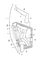
- Patent Document 1 discloses a conventional zone air conditioning system.
- an air conditioning system 100 for a vehicle disclosed in Patent Document 1 includes a suction port 102 opened on the upper surface of a seat cushion 101 a of a seat 101, a headrest of a seat 101 [headrest ]
- the blower outlet [blow-out port] 103 opened above 101c, and the duct 104 which connects the suction inlet 102 and the outlet 103 are provided.
- a blower 105, an evaporator 106, and a heater 107 are arranged on the air passage [blow passageway] in the duct 104.
- Interior air is sucked from the suction port 102, and the sucked air is converted into conditioned air at a desired temperature by the evaporator 106 and the heater 107.
- the conditioned air is blown out from the air outlet 103.
- the conditioned air blown out is sucked again from the suction port 102 through the occupant.
- Zone air conditioning improves quick cooling performance and quick heating performance.
- Patent Document 2 discloses another conventional zone air conditioning system.
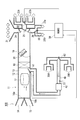
- a vehicle air conditioning system 110 disclosed in Patent Document 2 includes a main air conditioner [main air-conditioner] (not shown) disposed in an instrument panel, and a seat air conditioner.
- the seat air conditioner 111 includes a first suction port 113 opened at the upper part of the seat back 112b of the seat 112, a first air outlet 114 opened at the lower part of the seat back 112b, the first air inlet 113 and the first air outlet 114.
- the first air passage 115 that communicates with the second air inlet 120, the second air inlet 120 that is opened on the lower surface of the seat cushion 112a, the second air outlet 121 that is opened on the upper surface of the seat cushion 112a, and the second air inlet 120 and second The 2nd ventilation path 122 which connects the blower outlet 121 is provided.
- a blower 116 and a heat exchanger 117 are disposed in the first air passage 115, and a blower 123 and a heat exchanger 124 are disposed in the second air passage 122.
- Below the second suction port 120 a tip of a duct 130 extending from the main air conditioner is opened.
- Conditioned air from the main air conditioner is blown out from the front of the passenger compartment to the passenger compartment.
- the conditioned air blown out is sucked from the first suction port 113 through the periphery of the occupant and collected. Thereby, the flow of the conditioned air to the passenger compartment space behind the first suction port 113 is suppressed.
- the conditioned air sucked from the first suction port 113 passes through the heat exchanger 117 and is blown out from the first air outlet 114 to the passenger compartment. Further, the conditioned air from the main air conditioner is blown out from the duct 130 to the lower surface of the seat cushion 112a.
- the conditioned air is sucked from the second suction port 120, passes through the heat exchanger 124, and is blown out from the second air outlet 121 to the passenger compartment.
- the conditioned air blown from the first air outlet 114 and the second air outlet 121 flows to the front of the passenger compartment through the periphery of the occupant and is returned to the main air conditioner again.
- a strong flow of the conditioned air is formed around the occupant, thereby realizing zone air conditioning. Immediate cooling and warming are improved by zone air conditioning.
- Japanese Patent No. 3301109 Japanese Unexamined Patent Publication No. 5-286346
- conditioned air is generated using a heat exchanger of a main air conditioner (not shown).
- the conditioned air blown from the first air outlet 114 and the second air outlet 121 flows through the vehicle interior only by the suction force of the inside air introduction port of the main air conditioner and is returned to the main air conditioner. Since the conditioned air that has lost a large amount of heat while flowing through the passenger compartment is returned to the main air conditioner, the load on the main air conditioner is large despite the zone air conditioning.
- the conditioned air blown from the first air outlet 114 and the second air outlet 121 of the seat 112 is opened at a position closer to the inside air inlet of the main air conditioner and the first air inlet 113 and the second air outlet of the seat 112.
- the air-conditioning air blown out from the first air outlet 114 and the second air outlet 121 does not return to the main air conditioner because it is easily sucked from the second air inlet 120. Therefore, without the heat exchangers 117 and 124 of the seat air conditioner 111, a circulating flow of indoor air that is not at a desired temperature is formed. In other words, heat exchangers 117 and 124 of the seat air conditioner 111 are required to prevent the circulation of indoor air that is not at a desired temperature and to realize comfortable zone air conditioning, resulting in a complicated system and high cost. End up.
- the air conditioning system 100 or 110 shown in FIG. 11 or FIG. 12 is configured to perform zone air conditioning for each occupant, the air conditioning system 100 or 110 becomes very complicated and the cost increases.
- the air conditioning system 100 or 110 is configured to perform zone air conditioning for a plurality of passengers (for example, a driver seat and a passenger seat passenger), zone air conditioning cannot be performed for each passenger, From the viewpoint of energy and cost, it becomes an excessive zone air conditioning system.
- the average occupancy rate of passenger cars is 1.4 (in Japan) and responding to passengers' various requests for air conditioning, a system that can easily change the zone air-conditioning area is desired. Yes.
- An object of the present invention is to realize a vehicle that can realize a simplified system and a low cost, can perform comfortable zone air conditioning that can save energy by reducing an air conditioning load, and can easily change the zone air conditioning region. It is to provide an air conditioning system for use.
- a feature of the present invention is an air conditioning system for a vehicle, which includes a main blower, a main duct, and a heat exchange unit, and converts the air sucked into the main duct by the blower into a desired conditioned air by the heat exchange unit.
- An air conditioner configured to be converted and blown into the passenger compartment, a plurality of suction ports arranged around the occupant's seat, and one end portion connected to the plurality of suction ports, the plurality of suction ports A sub duct capable of sucking the conditioned air and returning it to the air conditioner, and a suction port selector for selecting at least one suction port used for sucking the conditioned air from the plurality of suction ports
- an air conditioning system for a vehicle comprising:
- the conditioned air blown into the passenger compartment by the air conditioner is sucked from the suction port arranged around the passenger's seat.
- the conditioned air is recovered and the conditioned air flowing backward from the suction port is suppressed, and strong and comfortable zone air conditioning can be performed.
- the conditioned air sucked from the suction port is returned to the air conditioner through the sub duct.
- zone air-conditioning mode air-conditioning air at a desired temperature can be generated by the heat exchange unit of the air conditioner. Therefore, installation of a heat exchange unit dedicated to zone air-conditioning is not essential, and simplification and cost reduction of the system can be realized. . Furthermore, since the conditioned air sucked from the suction port is not blown out into the passenger compartment, a circulating flow having an undesired temperature is not formed around the occupant unlike the air conditioning system 110 shown in FIG. 12 described above.
- the zone air conditioning area can be variably controlled.
- the plurality of suction ports are disposed around the driver's seat side seat and the passenger seat side seat, and the suction port selector is (i) the suction port and the passenger seat around the driver seat side seat. Both of the suction ports around the side seat, (ii) only the suction port around the driver seat side seat, or (ii) only the suction port around the passenger seat side seat It is preferable to select the at least one suction port used for suction.
- the air conditioner includes an air outlet that blows the conditioned air around the driver side seat, an air outlet that blows the conditioned air around the passenger seat, and the suction port.
- An air outlet selector that selects at least one air outlet used for blowing out the conditioned air, and the air outlet selector is connected to the at least one air inlet selected by the air inlet selector.
- the air outlet when the air outlet is a vent air outlet, when the air outlet is a foot air outlet, the air outlet may be a vent air outlet and a foot air outlet.
- the other end of the sub duct is connected to the main duct upstream from the main blower.
- the other end of the sub duct is connected to the main duct between the blower and the heat exchanging unit, and the sub duct is selected from the at least one suction port selected by the suction port selector. It is preferable that a sub-blower that allows air to flow in is provided.
- the other end of the sub-duct is opened as an opening in the vicinity of the inside air inlet of the air conditioner, and the inside of the sub-duct from the at least one inlet selected by the inlet selector. It is preferable to include a sub blower that allows air to flow into the fan.
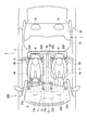
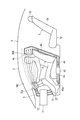
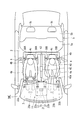
- FIGS. 1 and 2 show an air conditioning system 10A of the first embodiment.
- the vehicle 1 has an instrument panel 3 in the foremost part in the passenger compartment 2.
- two front seats (driver's seat and front passenger seat) 4 and one long rear seat 5 are provided.
- Each front seat 4 has a seat cushion 4a, a seat back 4b, and a headrest 4c.
- the rear seat 5 has a seat cushion 5a, a seat back 5b, and two headrests 5c.
- the air conditioning system 10A includes an air conditioning apparatus 11, suction ports 30A and 30B disposed around the front seat 4, and the suction ports 30A and 30B. And a sub duct 40 communicating with the main duct 13. An air passage is formed inside the main duct 13.
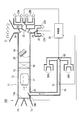
- the air conditioner 11 has an air conditioning unit 12 arranged inside the instrument panel 3. As shown in FIG. 3, a main duct 13 is provided in the air conditioning unit 12. The uppermost stream of the main duct 13 is provided with an outside air introduction port 14 for introducing air outside the vehicle compartment 2 (outside air) and an inside air introduction port 15 for introducing air inside the vehicle compartment 2 (inside air).
- the outside air introduction port 14 is opened and closed by an intake door 16a, and the inside air introduction port 15 is opened and closed by an intake door 16b.
- a blower 17 In the main duct 13, a blower 17, an evaporator (heat exchange unit) 18, and a heater core (heat exchange unit) 19 are arranged in this order from the upstream.
- the evaporator 18 is a cooling source
- the heater core 19 is a heating source.
- a mix door 20 is provided between the evaporator 18 and the heater core 19.
- the blower 17 rotates the fan and sucks the inside air and the outside air into the main duct 13.
- the evaporator 18 is arrange
- the heater core 19 is disposed in a substantially half area of the cross section of the main duct 13 and heats the air.
- the mix door 20 adjusts the ratio of the air volume that passes through the heater core 19 and the air volume that bypasses the heater core 19. By changing this air volume ratio, conditioned air at a desired temperature is generated.
- a defroster outlet 21, vent outlets 22a and 22b, and foot outlets 23a and 23b are provided downstream of the heater core 19, a defroster outlet 21, vent outlets 22a and 22b, and foot outlets 23a and 23b are provided.
- the defroster outlet 21 blows out the conditioned air to the windshield.
- the vent outlets 22a and 22b are composed of a vent outlet 22a in the driver's seat and a vent outlet 22b in the passenger seat, and blow out conditioned air to the upper body of the occupant.
- the foot air outlets 23a and 23b are composed of a foot air outlet 23a in the driver's seat and a foot air outlet 23b in the passenger seat, and blow out conditioned air to the lower body of the occupant.
- the defroster outlet 21 is opened and closed by a defroster door 24.
- the vent outlets 22a and 22b are opened and closed by a vent door 25.
- the foot outlets 23 a and 23 b are opened and closed by a foot door 26.
- a [served as a blow-out port selector] vent outlet selection door 60 provided as an outlet selector is located downstream of the vent door 25 in the main duct 13 and is on the driver side. It is arranged at a branch position between the outlet 22a and the passenger seat side vent outlet 22b.
- the vent outlet selection door 60 includes a driver seat side position for sending conditioned air to the driver seat side vent outlet 22a, a passenger seat side position for sending conditioned air to the passenger seat side vent outlet 22b, and a driver seat side vent outlet. It is possible to switch to an intermediate position for sending conditioned air to both 22a and the passenger seat side vent outlet 22b.
- a foot outlet selection door 61 provided as an outlet selector is arranged at a branch position between the driver seat side foot outlet 23a and the passenger seat side foot outlet 23b, downstream of the foot door 26 in the main duct 13.
- the foot outlet selection door 61 includes a driver seat side position for sending conditioned air to the driver seat side foot outlet 23a, a passenger seat side position for sending conditioned air to the passenger seat side foot outlet 23b, and a driver seat side foot outlet. It is possible to switch to an intermediate position for sending conditioned air to both the 23a and the passenger seat side foot outlet 23b.
- vent outlet selection door 60 and the foot outlet selection door 61 are controlled by a controller 50.
- the suction port 30A of the right front seat 4 (or the suction port 30B of the left front seat 4) is provided on both sides of the headrest 4c at the upper part of the seat back 4b. It has been. A total of four inlets 30 ⁇ / b> A and 30 ⁇ / b> B are opened immediately after the upper body of the occupant of the front seat 4.
- one end of the sub duct 40 is connected to the suction ports 30A and 30B.
- the other end of the sub duct 40 is connected to the main duct 13 upstream from the blower 17.
- a selection door 41 is arranged at a connection position of the sub duct 40 with the main duct 13.
- the selection door 41 can block communication between the inside of the sub duct 40 and the inside of the main duct 13.
- the operation of the selection door 41 is controlled by the control unit 50.
- a suction port selection door 62 provided as a suction port selector [suction port selector] is arranged at a confluence position between the driver seat side suction port 30A and the passenger seat side suction port 30B in the sub duct 40.
- the suction port selection door 62 includes a driver seat side position for sucking conditioned air from the driver seat side suction port 30A, a passenger seat side position for sucking conditioned air from the passenger seat side suction port 30B, and the driver seat side suction port 30A and the assistant. It is possible to switch to an intermediate position for sucking conditioned air from both of the seat side suction ports 30B.
- the suction port selection door 62 is controlled by the control unit 50.
- a temperature sensor S1 is arranged in the sub duct 40.
- the temperature sensor S1 detects the temperature of the conditioned air sucked from the suction ports 30A and 30B.
- the detection data of the temperature sensor S1 is output to the control unit 50.
- Various commands (settings) related to air conditioning are input to the operation panel (not shown).
- an overall air conditioning mode for air-conditioning the entire space of the passenger compartment 2 or a zone air conditioning mode for preferentially air-conditioning the front seat space can be selected.
- the zone air-conditioning mode three types of zones can be specified: the driver side, the passenger side, the driver side only, and the passenger side only.
- the control unit 50 controls the operation of the air conditioner 11 and the selection positions of the selection door 41, the vent outlet selection door 60, the foot outlet selection door 61, and the suction inlet selection door 62 according to a command from the operation panel. For example, when the overall air conditioning mode is selected, the control unit 50 sets the vent outlet selection door 60, the foot outlet selection door 61, and the inlet selection door 62 to the intermediate positions and closes the selection door 41, A temperature sensor (not shown) in the vicinity of the instrument panel 3 is used to control the blowout temperature of the conditioned air. On the other hand, when the zone air-conditioning mode is selected, the control unit 50 opens the selection door 41 and controls the air-conditioning air blowing temperature and the like using the temperature sensor S1 in the sub duct 40.
- the control unit 50 determines whether the vent air outlet selection door 60, the foot air outlet selection door 61, and the air inlet according to the designated area in the zone air-conditioning mode (driver seat side and passenger seat side, driver seat side only, passenger seat side only). The position of the selection door 62 is controlled.
- the operation of the above-described air conditioning system 10A will be described.
- air is sucked into the main duct 13 from the outside air inlet 14 and the inside air inlet 15 by the blower 17.
- the sucked air is converted into conditioned air at a desired temperature by the evaporator 18 and the heater core 19, and the conditioned air is supplied to the vehicle from at least one outlet 21, 22 a, 22 b, 23 a, 23 b (for example, vent outlet 22 a, 22 b). It is blown out into the chamber 2.
- the selection door 41 is closed. Thereby, the conditioned air is not sucked from the suction ports 30A and 30B. Therefore, the conditioned air blown into the passenger compartment 2 by the air conditioner 11 forms a flow that reaches almost the entire interior of the passenger compartment 2, and the entire passenger compartment 2 is air-conditioned.
- the selection door 41 is opened. Moreover, the suction inlet selection door 62, the vent blower outlet selection door 60, and the foot blower outlet selection door 61 are set to an intermediate position. Accordingly, as shown in FIG. 2, when the air-conditioning air blowing mode set in addition to the air-conditioning mode is the vent mode, the air-conditioning is performed from both the driver seat side vent air outlet 22a and the passenger seat side vent air outlet 22b. Wind is blown into the passenger compartment 2. On the other hand, when the blowing mode is the foot mode, conditioned air is blown into the passenger compartment 2 from both the driver's seat side foot outlet 23a and the passenger's seat side foot outlet 23b.
- the conditioned air blown into the passenger compartment 2 is sucked from both the driver seat side suction port 30A and the passenger seat side suction port 30B by the suction force of the blower 17.
- the sucked conditioned air is returned to the air conditioning unit 12 through the sub duct 40.
- the conditioned air flows intensively (preferentially) around the passenger on the driver's seat side front seat 4 and the passenger on the passenger seat side front seat 4 and is collected from the suction ports 30A and 30B.
- the flow of the conditioned air to the passenger compartment space behind the suction ports 30A and 30B is also suppressed. As a result, a zone air-conditioning region is formed around the driver seat side front seat 4 and the passenger seat side front seat 4 in the passenger compartment 2.
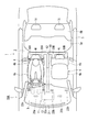
- the selection door 41 is opened. Moreover, the suction inlet selection door 62, the vent outlet selection door 60, and the foot outlet selection door 61 are set to the driver's seat side position. Thereby, as shown in FIG. 4, in the vent mode, the conditioned air is blown into the passenger compartment 2 only from the driver's seat side vent outlet 22a. On the other hand, in the foot mode, conditioned air is blown into the passenger compartment 2 only from the driver's seat side foot outlet 23a.
- the conditioned air blown into the passenger compartment 2 is sucked only from the driver seat side suction port 30 ⁇ / b> A by the suction force of the blower 17.
- the sucked conditioned air is returned to the air conditioning unit 12 through the sub duct 40.
- the conditioned air flows intensively (preferentially) around the passenger on the driver's seat side front seat 4 and is collected from the suction port 30A.
- the flow to the passenger compartment space behind the suction port 30A is also suppressed. As a result, a zone air-conditioning region is formed around the driver seat side front seat 4 in the passenger compartment 2.
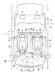
- the suction selection door 41 is opened. Moreover, the suction inlet selection door 62, the vent outlet selection door 60, and the foot outlet selection door 61 are set to a passenger seat side position. Thus, as shown in FIG. 5, in the vent mode, the conditioned air is blown into the passenger compartment 2 only from the passenger seat side vent outlet 22b. On the other hand, in the foot mode, conditioned air is blown into the passenger compartment 2 only from the passenger seat side foot outlet 23b.
- the conditioned air blown into the passenger compartment 2 is sucked only from the passenger seat side suction port 30 ⁇ / b> B by the suction force of the blower 17.
- the sucked conditioned air is returned to the air conditioning unit 12 through the sub duct 40.
- the conditioned air flows intensively (preferentially) around the passenger on the passenger seat side front seat 4 and is collected from the inlet 30B.
- the flow to the passenger compartment space behind the suction port 30B is also suppressed. As a result, a zone air-conditioning region is formed around the front passenger seat 4 in the passenger compartment 2.
- the conditioned air at the desired temperature is generated using the evaporator 18 and the heater core 19 of the air conditioning unit 12.
- Installation of a dedicated heat exchange unit is not essential, and simplification and cost reduction of the system can be realized.
- the conditioned air sucked from the suction ports 30 ⁇ / b> A and 30 ⁇ / b> B flows through the sub duct 40 over the entire path returned to the air conditioner 11, and is returned to the air conditioner 11 while suppressing heat loss as much as possible. As a result, the air conditioning load of the air conditioner 11 is reduced.
- the suction port selection door 62 can select from which of the suction ports 30A and 30B (including both) the conditioned air is sucked, the zone air conditioning region can be variably controlled as described above.
- the system configuration can be simplified and the cost can be reduced.
- immediate cooling and immediate warming are improved by zone air conditioning.
- the above embodiment can be realized simply by installing the suction ports 30A and 30B, the sub duct 40, etc., and retrofit installation can be easily performed.
- the entire air conditioning mode and the zone air conditioning mode can be selectively executed by the selection door 41. Moreover, it is possible to easily switch between the overall air conditioning mode and the zone air conditioning mode simply by controlling the operation of the selection door 41.
- the suction of air-conditioned air is selected from either the driver seat side suction port 30A and the passenger seat side suction port 30B, or either the driver seat side suction port 30A or the passenger seat side suction port 30B by the suction port selection door 62. Done. Therefore, in the zone air-conditioning mode, one area can be selected from the three zone air-conditioning areas (driver seat side and passenger seat side, driver seat side only, passenger seat side only).
- the suction inlet and the outlet (operating) corresponding to each other by the inlet selector (suction inlet selection door 62) and the outlet selector (the vent outlet selecting door 60 or the foot outlet selecting door 61).
- the seat side suction port 30A and the driver seat vent outlet 22a or the driver seat foot outlet 23a: the passenger seat side inlet 30B and the passenger seat side vent outlet 22b or the passenger seat side foot outlet 23b) are interlocked. Can be selected. Therefore, the blowing of the conditioned air that does not contribute to the zone air conditioning from the air conditioning unit 12 is suppressed, and only the conditioned air that effectively contributes to the zone air conditioning is blown out from the air conditioning unit 12. As a result, the air conditioning load of the air conditioner 11 is further reduced, and energy saving can be realized.
- the conditioned air can be sucked from the suction ports 30A and 30B by using the suction force of the blower 17. For this reason, it is not necessary to separately provide a blower only for suction from the suction ports 30A and 30B. As a result, further simplification and cost reduction of the system configuration can be realized.
- the suction ports 30A and 30B are provided in the front seat 4.
- the front seat 4 is an existing component that is always provided, and is most suitable for disposing the suction ports 30A and 30B, and the suction ports 30A and 30B are easy to install.
- the suction ports 30A and 30B are provided in the upper part of the seat back 4b. Airflows of conditioned air (warm air, cold air) blown out from the vent outlets 22a and 22b are likely to gather above the passenger compartment 2 without a shield. Therefore, the conditioned air can be efficiently sucked by the suction ports 30A and 30B provided in the upper part of the seat back 4b, and the recovery rate of the conditioned air is improved.
- conditioned air warm air, cold air
- a temperature sensor S1 for detecting the temperature of the conditioned air sucked from the suction ports 30A and 30B is provided. Therefore, in the zone air-conditioning mode, the temperature of the air-conditioning air blown from the air conditioner 11 can be controlled based on the temperature of the air-conditioning air that has actually passed around the passenger, and the air-conditioning temperature can be accurately controlled.
- FIGS. 6 and 7 show an air conditioning system 10B of the second embodiment.
- the connection position of the other end of the sub-duct 40 is different from the air conditioning system 10A of the first embodiment described above.
- the other end of the sub duct 40 is connected to the main duct 13 between the blower 17 and the evaporator 18.
- the sub duct 40 is provided with a sub blower 42 that sucks air from the suction ports 30A and 30B.
- the sub blower 42 is controlled by the control unit 50.
- the operation of the air conditioning system 10B described above will be described.
- air is sucked into the main duct 13 from the outside air inlet 14 and the inside air inlet 15 by the blower 17.
- the sucked air is converted into conditioned air at a desired temperature by the evaporator 18 and the heater core 19, and the conditioned air is supplied to the vehicle from at least one outlet 21, 22 a, 22 b, 23 a, 23 b (for example, vent outlet 22 a, 22 b). It is blown out into the chamber 2.
- the selection door 41 is closed and the sub blower 42 is not driven. Thereby, the conditioned air is not sucked from the suction ports 30A and 30B. Therefore, the conditioned air blown into the passenger compartment 2 by the air conditioner 11 forms a flow that reaches almost the entire interior of the passenger compartment 2, and the entire passenger compartment 2 is air-conditioned.
- the selection door 41 is opened and the sub-blower 42 is driven. Accordingly, the conditioned air is sucked from the suction ports 30 ⁇ / b> A and 30 ⁇ / b> B by the suction force of the sub blower 42. Therefore, the conditioned air blown into the passenger compartment 2 from the air conditioner 11 is sucked from both the driver seat side suction port 30A and the passenger seat side suction port 30B. The sucked conditioned air is returned to the air conditioning unit 12 through the sub duct 40. The conditioned air flows intensively (preferentially) around the passenger on the front seat 4 and is collected by the suction ports 30A and 30B. The flow of conditioned air to the passenger compartment space behind the suction ports 30A and 30B is also suppressed. As a result, a zone air-conditioning area is formed around the front seat 4 in the passenger compartment 2.
- the vent outlet selection door 60, the foot outlet selection door 61, and the inlet selection is controlled, and a flow of conditioned air similar to that of the first embodiment is formed.
- the air conditioning system 10B simplification of the system configuration and cost reduction can be realized as in the first embodiment.
- comfortable zone air conditioning can be performed while realizing energy saving by reducing the air conditioning load.
- immediate cooling and immediate warming are improved by zone air conditioning.
- the zone air-conditioning area can be easily variably controlled.
- the entire air conditioning mode and the zone air conditioning mode can be selectively executed by controlling the selection door 41 and the sub blower 42.
- the suction amount of the suction ports 30A and 30B can be adjusted independently of the blow amount of the air conditioner 11.
- FIGS. 8 to 10 show an air conditioning system 10C of the third embodiment.
- the air conditioning system 10C is different from the air conditioning system 10A of the first embodiment described above in that the sub duct 40 is not directly connected to the main duct 13.
- the sub duct 40 is provided with the sub blower 42 described in the second embodiment, and the auxiliary internal air introduction port 27 is provided near the internal air introduction port 15 of the main duct 13. Is also different from the air conditioning system 10A of the first embodiment described above.
- the other end of the duct 40 is not connected to the air conditioning unit 12.
- the opening 40 a at the other end of the duct 40 is opened toward the inside air introduction port 15 and the auxiliary room air introduction port 27 in the vicinity of the room air introduction port 15 and the auxiliary room air introduction port 27 of the air conditioning unit 12. Therefore, in this embodiment, the selection door 41 of 1st Embodiment is not provided, but the sub air blower 42 demonstrated in 2nd Embodiment is provided instead.
- the sub blower 42 is controlled by the control unit 50.
- the sub blower 42 In the overall air conditioning mode, the sub blower 42 is not driven. Thereby, the conditioned air is not sucked from the suction ports 30A and 30B. Therefore, the conditioned air blown into the passenger compartment 2 by the air conditioner 11 forms a flow that spreads over almost the entire interior of the passenger compartment 2, and the entire passenger compartment 2 is air-conditioned.
- the sub blower 42 In the zone air conditioning mode (driver seat side and passenger seat side), the sub blower 42 is driven. Accordingly, the conditioned air is sucked from the suction ports 30 ⁇ / b> A and 30 ⁇ / b> B by the suction force of the sub blower 42. Therefore, the conditioned air blown into the passenger compartment 2 from the air conditioner 11 is sucked from both the driver seat side suction port 30A and the passenger seat side suction port 30B. The sucked conditioned air is blown out from the opening 40a near the air conditioning unit 12 through the sub duct 40, and immediately after that, is sucked into the air conditioning unit 12 from the inside air introduction port 15 or the auxiliary inside air introduction hole 27.
- the air blown from the opening 40a is sucked into the air conditioning unit 12 from the inside air introduction port 15.
- the auxiliary inside air inlet 27 is closed by the auxiliary suction door 28.
- the air blown from the opening 40 a is sucked into the air conditioning unit 12 from the auxiliary inside air introduction port 27.
- the auxiliary inside air inlet 27 is opened by the auxiliary suction door 28.
- the conditioned air flows intensively (preferentially) around the passenger on the front seat 4 and is collected from the suction ports 30A and 30B.
- the flow to the passenger compartment space behind the suction ports 30A and 30B is also suppressed.
- a zone air-conditioning area is formed around the front seat 4 in the passenger compartment 2.
- the vent outlet selection door 60, the foot outlet selection door 61, and the inlet selection is controlled, and a flow of conditioned air similar to that of the first embodiment is formed.
- zone air-conditioning mode air-conditioning air having a desired temperature is generated using the evaporator 18 and the heater core 19 of the air-conditioning unit 12, so that it is not essential to install a heat exchanging unit dedicated to zone air-conditioning, simplifying the system and reducing the cost. Can be realized.
- the conditioned air sucked from the suction ports 30 ⁇ / b> A and 30 ⁇ / b> B flows through the sub duct 40 in most of the path returned to the air conditioner 11, and is returned to the air conditioner 11 while suppressing heat loss as much as possible. As a result, the air conditioning load of the air conditioner 11 is reduced.
- the suction port selection door 62 can select from which of the suction ports 30A and 30B (including both) the conditioned air is sucked, the zone air conditioning region can be variably controlled as described above.
- the system configuration can be simplified and the cost can be reduced.
- immediate cooling and immediate warming are improved by zone air conditioning.
- the above embodiment can be realized simply by installing the suction ports 30A and 30B, the sub duct 40, the sub blower 42, and the like, and retrofit installation can be easily performed.
- the entire air conditioning mode and the zone air conditioning mode can be selectively performed, and the switching can be easily controlled.
- the opening 40a of the sub duct 40 is disposed in the vicinity of the inside air introduction port 15 (auxiliary inside air introduction hole 27) of the air conditioning unit 12, and is opened toward the inside air introduction port 15 (auxiliary inside air introduction hole 27). Yes. Therefore, the air blown out from the opening 40a is reliably and quickly collected in the air conditioning unit 12 by the synergistic action of the suction force of the blower 17 of the air conditioning unit 12 and the blowing output of the sub blower 42 of the sub duct 40.
- the air conditioning unit 12 has an auxiliary inside air inlet 27 and an auxiliary suction door 28. Therefore, since the air blown from the opening 40a can be collected in the air conditioning unit 12 by the auxiliary inside air introduction port 27, zone air conditioning can be performed even when outside air is introduced.
- the auxiliary air inlet 27 is provided in the main duct 13 of the air conditioning unit 12 and the auxiliary air inlet 27 for opening and closing the auxiliary air inlet 27 is provided, but the auxiliary air inlet 27 and the auxiliary air door 28 are provided. It may not be provided.
- the intake doors 16a and 16b are controlled to open both the outside air introduction port 14 and the inside air introduction port 15. In this way, it is not necessary to provide the auxiliary inside air inlet 27 and the auxiliary suction door 28, and the system configuration can be simplified.
- the suction amount of the suction ports 30A and 30B can be adjusted independently of the blow amount of the air conditioner 11.
- zone air conditioning can be performed for the passenger on the front seat 4 and the zone air conditioning area is set for each of the passenger on the driver side front seat 4 and the passenger on the passenger side front seat 4. it can. Furthermore, zone air conditioning may be set for each of the passengers on the right rear seat 5 and the passengers on the left rear seat 5, and the zone air conditioning may be performed for the passengers on the rear seat 5. That is, in this modified example, in addition to the configuration of any of the first to third embodiments, a plurality of suction openings opened around the rear seat 5 and conditioned air from these suction openings are air-conditioned.
- the apparatus includes a sub duct, and the sub duct for the rear seat 5 includes a suction port selection door. According to this configuration, the zone air conditioning region can be set not only for the passenger on the front seat 4 but also for the passenger on the rear seat 5. This modification is particularly effective for a vehicle having a large volume of the passenger compartment 2 such as a one-box car.
- the suction ports 30A to 30D are provided in the seat 4 or 5, but may be provided anywhere around the occupant's seat. Providing the suction ports 30A to 30D around the seat 4 or 5 is easy to install later.
- the zone air conditioning region may be set based on a manual operation, or may be automatically set based on a detection result of an occupant detector (for example, a seating sensor).
- an occupant detector for example, a seating sensor
Landscapes
- Physics & Mathematics (AREA)
- Thermal Sciences (AREA)
- Engineering & Computer Science (AREA)
- Mechanical Engineering (AREA)
- Air-Conditioning For Vehicles (AREA)
Abstract
車両用空気調和システムは、メイン送風機、メインダクト及び熱交換部を有し、前記送風機によって前記メインダクト内に吸い込んだ空気を前記熱交換部によって所望の空調風に変換して車室内に吹き出すよう構成された空気調和装置と、乗員のシート周辺に配置された複数の吸込口と、一側の端部が前記複数の吸込口に接続され、前記複数の吸込口から前記空調風を吸い込んで前記空気調和装置に戻すことの可能なサブダクトと、前記複数の吸込口の中から、前記空調風の吸い込みに使用される少なくとも一つの吸込口を選択する吸込口選択器と、を備えている。上記空気調和システムによれば、システムの単純化及び低コスト化を実現できると共に、空調負荷の低減による省エネルギー化の可能な快適なゾーン空調を行うことができ、かつ、ゾーン空調領域を簡単に可変できる。
Description
本発明は、車室内の一部(例えば、乗員の周囲)を空調領域とするゾーン空調(パーソナル空調)を行うことのできる車両用空気調和システム[an air-conditioning system for a vehicle]に関するものである。
車両用空気調和システムとして、車室全体ではなく乗員の周囲のみを空調するゾーン空調システムが提案されている。下記特許文献1は、従来のゾーン空調システムを開示している。特許文献1に開示されている車両用空気調和システム100は、図11に示されるように、シート101のシートクッション101aの上面に開口された吸込口[suction port]102、シート101のヘッドレスト[headrest]101cの上方に開口された吹出口[blow-out port]103、及び、吸込口102と吹出口103とを連通させるダクト104を備えている。ダクト104内の送風路[blow passageway]上には、送風機[blower]105、エバポレータ106、ヒータ107が配置されている。
室内空気[interior air]が吸込口102から吸い込まれ、吸い込まれた空気はエバポレータ106及びヒータ107によって所望温度の空調風[conditioned air]とされる。空調風は、吹出口103から吹き出される。吹き出された空調風は、乗員の周囲を通って再び吸込口102から吸い込まれる。このような空調風の循環によって乗員の周囲に空調風の流れが形成され、ゾーン空調が実現される。ゾーン空調によって即冷性[quick cooling performance]及び即暖性[quick heating performance]が向上される。
下記特許文献2は、他の従来のゾーン空調システムを開示している。特許文献2に開示されている車両用空気調和システム110は、図12に示されるように、インストルメントパネル内に配置されたメイン空調装置[main air-conditioner](図示せず)と、シート空調装置[in-seat air-conditioner]111とを備えている。シート空調装置111は、シート112のシートバック112bの上部に開口された第1吸込口113、シートバック112bの下部に開口された第1吹出口114、第1吸込口113と第1吹出口114とを連通させる第1送風路115、シートクッション112aの下面に開口された第2吸込口120、シートクッション112aの上面に開口された第2吹出口121、及び、第2吸込口120と第2吹出口121とを連通させる第2送風路122を備えている。第1送風路115には、送風機116及び熱交換器117が配置され、第2送風路122には、送風機123及び熱交換器124が配置されている。第2吸込口120の下方には、メイン空調装置から延設されたダクト130の先端が開口されている。
メイン空調装置からの所望温度の空調風は、車室前部から車室へと吹き出される。吹き出された空調風は、乗員の周辺を通って第1吸込口113から吸い込まれて、回収されるる。これにより、第1吸込口113より後方の車室空間への空調風の流れが抑制される。第1吸込口113から吸い込まれた空調風は、熱交換器117を通過して第1吹出口114から車室へと吹き出される。また、メイン空調装置からの所望温度の空調風は、ダクト130からシートクッション112aの下面へと吹き出される。空調風は、第2吸込口120から吸い込まれ、熱交換器124を通過して第2吹出口121から車室へと吹き出される。第1吹出口114及び第2吹出口121から吹き出された空調風は、乗員の周辺を通って車室内前方に流れて、再びメイン空調装置へと戻される。このような空調風の循環によって、乗員の周囲に空調風の強い流れが形成され、ゾーン空調が実現される。ゾーン空調によって即冷性及び即暖性が向上される。
しかし、上述した図11に示される空気調和システム100では、ゾーン空調専用のエバポレータ106及びヒータ107を設ける必要があるので、システムの複雑化や高コスト化を招いてしまう。
また、上述した図12に示される空気調和システム110では、メイン空調装置(図示せず)の熱交換器を利用して空調風が生成される。また、第1吹出口114や第2吹出口121から吹き出された空調風は、メイン空調装置の内気導入口の吸込力のみによって車室内部を流れてメイン空調装置に戻される。車室内部を流れる間に熱を大きく損失した空調風がメイン空調装置に戻されるので、ゾーン空調であるのにもかかわらずメイン空調装置への負荷が大きい。また、シート112の第1吹出口114や第2吹出口121から吹き出された空調風は、メイン空調装置の内気導入口よりも近い位置に開口されているシート112の第1吸込口113や第2吸込口120から吸い込まれ易く、第1吹出口114や第2吹出口121から吹き出された空調風がメイン空調装置に戻らない。従って、シート空調装置111の熱交換器117,124がないと、所望温度でない室内空気の循環流が形成されてしまう。すなわち、所望温度でない室内空気の循環流を防止して快適なゾーン空調を実現するためにはシート空調装置111の熱交換器117,124が必要となり、システムの複雑化や高コスト化を招いてしまう。
また、図11や図12に示される空気調和システム100又は110が、乗員一人毎にゾーン空調を行うように構成されると、非常に複雑化すると共に、コストが増加する。一方、空気調和システム100又は110が、複数の乗員(例えば運転席と助手席の乗員)に対してゾーン空調を行うように構成されると、乗員一人毎にゾーン空調を行うことができず、エネルギーやコストの観点からは過剰なゾーン空調システムとなる。また、乗用車の平均乗車率が1.4人である(日本の場合)ことや、乗員の様々な空調に対する要望に対応することを考慮すると、ゾーン空調領域を簡単に可変できるシステムが望まれている。
本発明の目的は、システムの単純化及び低コスト化を実現できると共に、空調負荷の低減による省エネルギー化の可能な快適なゾーン空調を行うことができ、かつ、ゾーン空調領域を簡単に可変できる車両用空気調和システムを提供することにある。
本発明の特徴は、車両用空気調和システムであって、メイン送風機、メインダクト及び熱交換部を有し、前記送風機によって前記メインダクト内に吸い込んだ空気を前記熱交換部によって所望の空調風に変換して車室内に吹き出すよう構成された空気調和装置と、乗員のシート周辺に配置された複数の吸込口と、一側の端部が前記複数の吸込口に接続され、前記複数の吸込口から前記空調風を吸い込んで前記空気調和装置に戻すことの可能なサブダクトと、前記複数の吸込口の中から、前記空調風の吸い込みに使用される少なくとも一つの吸込口を選択する吸込口選択器と、を備えている車両用空気調和システムを提供する。
上記特徴によれば、空気調和装置によって車室内に吹き出された空調風は、乗員のシート周辺に配置された吸込口から吸い込まれる。これにより、空調風が回収されると共に吸込口より後方に流れる空調風が抑制され、強く快適なゾーン空調を行うことができる。また、吸込口から吸い込まれた空調風は、サブダクトを通って空気調和装置に戻される。このような空調風の循環によって、乗員の周囲に空調風の快適な流れが形成され、好適なゾーン空調が形成される。
また、ゾーン空調モードでは、空気調和装置の熱交換部によって所望温度の空調風が生成できるので、ゾーン空調専用の熱交換部の設置が必須ではなく、システムの単純化や低コスト化を実現できる。さらに、吸込口から吸い込まれた空調風は、車室内に一切吹き出されないので、上述した図12に示される空気調和システム110のように所望温度でない循環流が乗員周辺に形成されることがない。
また、吸込口選択器によって空調風の吸込口を選択できるため、ゾーン空調領域を可変制御できる。
ここで、前記複数の吸込口が、運転席側シート及び助手席側シートの周辺に配置され、前記吸込口選択器が、(i)前記運転席側シートの周辺の前記吸込口及び前記助手席側シートの周辺の前記吸込口の双方、(ii)前記運転席側シートの周辺の前記吸込口のみ、又は、(ii)前記助手席側シートの周辺の前記吸込口のみ、を前記空調風の吸い込みに使用される前記少なくとも一つの吸込口として選択することが好ましい。
さらに、前記空気調和装置が、前記運転手側シートの周辺に前記空調風を吹き出す吹出口と、前記助手席側シートの周辺に前記空調風を吹き出す吹出口と、前記吸込口の中から、前記空調風の吹き出しに使用される少なくとも一つの吹出口を選択する吹出口選択器とをさらに備えており、前記吹出口選択器が、前記吸込口選択器によって選択された前記少なくとも一つの吸込口に対応させて、前記空調風の吹き出しに使用される前記少なくとも一つの吹出口を協調選択する、ことが好ましい。
ここで、前記吹出口がベント吹出口である場合、前記吹出口がフット吹出口である場合、前記吹出口がベント吹出口及びフット吹出口である場合、がある。
また、前記サブダクトの他側の端部が、前記メイン送風機より上流で前記メインダクトと接続されている、ことが好ましい。
あるいは、前記サブダクトの他側の端部が、前記送風機と前記熱交換部との間で前記メインダクトと接続されており、前記吸込口選択器によって選択された前記少なくとも一つの吸込口から前記サブダクト内に空気を流入させるサブ送風機を備えている、ことが好ましい。
あるいは、前記サブダクトの他側の端部が、前記空気調和装置の内気導入口の近傍で開口部として開口されており、前記吸込口選択器によって選択された前記少なくとも一つの吸込口から前記サブダクト内に空気を流入させるサブ送風機を備えている、ことが好ましい。
以下、実施形態を図面に基づいて説明する。
(第1実施形態)
図1~図5は第1実施形態の空気調和システム10Aを示している。図1及び図2に示されるように、車両1は、車室2内の最前部にインストルメントパネル3を有している。車室2内には、二つのフロントシート(運転席、助手席)4と一つの長いリアシート5とが設けられている。各フロントシート4は、シートクッション4a、シートバック4b、ヘッドレスト4cを有している。リアシート5は、シートクッション5a、シートバック5b、二つのヘッドレスト5cを有している。
図1~図5は第1実施形態の空気調和システム10Aを示している。図1及び図2に示されるように、車両1は、車室2内の最前部にインストルメントパネル3を有している。車室2内には、二つのフロントシート(運転席、助手席)4と一つの長いリアシート5とが設けられている。各フロントシート4は、シートクッション4a、シートバック4b、ヘッドレスト4cを有している。リアシート5は、シートクッション5a、シートバック5b、二つのヘッドレスト5cを有している。
図1~図3に示されるように、空気調和システム10Aは、空気調和装置11、フロントシート4周辺にそれぞれ配置された吸込口30A及び30Bと、これらの吸込口30A及び30Bを空気調和装置11のメインダクト13に連通させるサブダクト40とを備えている。メインダクト13の内部には、送風路が形成されている。
空気調和装置11は、インストルメントパネル3の内部に配置された空調ユニット12を有している。図3に示されるように、空調ユニット12内には、メインダクト13が設けられている。メインダクト13の最上流には、車室2外の空気(外気)を導入する外気導入口14と、車室2内の空気(内気)を導入する内気導入口15とが設けられている。外気導入口14はインテークドア16aによって開閉され、内気導入口15はインテークドア16bによって開閉される。
メインダクト13内には、送風機17、エバポレータ(熱交換部)18、及び、ヒータコア(熱交換部)19が、上流からこの順に配置されている。エバポレータ18は冷却源であり、ヒータコア19は加熱源である。エバポレータ18とヒータコア19との間には、ミックスドア20が設けられている。
送風機17は、そのファンを回転させてメインダクト13内に内気や外気を吸い込む。エバポレータ18は、メインダクト13を通る全ての空気が通過するように配置されており、空気を冷却する。ヒータコア19は、メインダクト13の断面のほぼ半分の領域に配置されており、空気を加熱する。ミックスドア20は、ヒータコア19を通過する風量とヒータコア19をバイパスする風量との割合を調整する。この風量割合を変化させることによって、所望温度の空調風が生成される。
ヒータコア19の下流には、デフロスタ吹出口21と、ベント吹出口22a及び22bと、フット吹出口23a及び23bとが設けられている。デフロスタ吹出口21は、空調風をフロントガラスにへと吹き出す。ベント吹出口22a及び22bは、運転席のベント吹出口22aと助手席のベント吹出口22bとからなり、空調風を乗員の上半身へと吹き出す。フット吹出口23a,23bは、運転席のフット吹出口23aと助手席のフット吹出口23bとからなり、空調風を乗員の下半身へと吹き出す。デフロスタ吹出口21は、デフロスタドア24によって開閉される。ベント吹出口22a及び22bは、ベントドア25によって開閉される。フット吹出口23a及び23bは、フットドア26によって開閉される。
図3に示されるように、吹出口選択器として設けられた[served as a blow-out port selector]ベント吹出口選択ドア60が、メインダクト13内のベントドア25より下流の、運転席側ベント吹出口22aと助手席側ベント吹出口22bとの分岐位置に配置されている。ベント吹出口選択ドア60は、運転席側ベント吹出口22aに空調風を送る運転席側位置と、助手席側ベント吹出口22bに空調風を送る助手席側位置と、運転席側ベント吹出口22a及び助手席側ベント吹出口22bの双方に空調風を送る中間位置とに切り替え可能である。
また、吹出口選択器として設けられたフット吹出口選択ドア61が、メインダクト13内のフットドア26より下流の、運転席側フット吹出口23aと助手席側フット吹出口23bとの分岐位置に配置されている。フット吹出口選択ドア61は、運転席側フット吹出口23aに空調風を送る運転席側位置と、助手席側フット吹出口23bに空調風を送る助手席側位置と、運転席側フット吹出口23a及び助手席側のフット吹出口23bの双方に空調風を送る中間位置とに切り替え可能である。
ベント吹出口選択ドア60及びフット吹出口選択ドア61は、制御部[controller]50によって制御される。
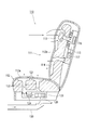
図1及び図2に示されるように、右フロントシート4の吸込口30A(又は、左フロントシート4の吸込口30B)は、シートバック4bの上部[upper portion]で、ヘッドレスト4cの両側に設けられている。合計四つの吸込口30A及び30Bは、フロントシート4の乗員の上半身のすぐ後に開口している。
図3に示されるように、サブダクト40の一端は、吸込口30A及び30Bに接続されている。サブダクト40の他端は、送風機17より上流でメインダクト13に接続されている。サブダクト40のメインダクト13との接続位置には、選択ドア[selector door]41が配されている。選択ドア41は、サブダクト40の内部とメインダクト13の内部との連通を遮蔽可能である。選択ドア41の動作は、制御部50によって制御される。
また、吸込口選択器[suction port selector]として設けられた吸込口選択ドア62が、サブダクト40内の運転席側吸込口30Aと助手席側吸込口30Bとの合流位置に配置されている。吸込口選択ドア62は、運転席側吸込口30Aから空調風を吸い込む運転席側位置と、助手席側の吸込口30Bから空調風を吸い込む助手席側位置と、運転席側吸込口30A及び助手席側吸込口30Bの双方から空調風を吸い込む中間位置とに切り替え可能である。吸込口選択ドア62は、制御部50によって制御される。
また、サブダクト40内には、温度センサS1が配されている。温度センサS1は、吸込口30A及び30Bから吸い込まれた空調風の温度を検出する。温度センサS1の検出データは、制御部50に出力される。
操作パネル(図示せず)には、空調に関する種々の指令(設定)が入力される。操作パネルによって、車室2全体空間を空調する全体空調モード、又は、前席空間を優先的に空調するゾーン空調モードが選択できる。なお、ゾーン空調モードでは、運転席側及び助手席側、運転席側のみ、助手席側のみの三種類のゾーンを指定できる。
制御部50は、操作パネルからの指令等によって空気調和装置11の動作や選択ドア41、ベント吹出口選択ドア60、フット吹出口選択ドア61及び吸込口選択ドア62の選択位置を制御する。例えば、制御部50は、全体空調モードが選択されると、ベント吹出口選択ドア60、フット吹出口選択ドア61及び吸込口選択ドア62をそれぞれ中間位置に設定すると共に選択ドア41を閉じて、インストルメントパネル3の近くの温度センサ(図示せず)を利用して空調風の吹き出し温度等を制御する。一方、制御部50は、ゾーン空調モードが選択されると、選択ドア41を開いて、サブダクト40内の温度センサS1を利用して空調風の吹き出し温度等を制御する。制御部50は、ゾーン空調モードでの指定領域(運転席側及び助手席側、運転席側のみ、助手席側のみ)に応じてベント吹出口選択ドア60、フット吹出口選択ドア61及び吸込口選択ドア62の位置を制御する。
上述した空気調和システム10Aの動作を説明する。空気調和装置11が駆動されると、送風機17によって外気導入口14や内気導入口15から空気がメインダクト13内に吸い込まれる。吸い込まれた空気は、エバポレータ18及びヒータコア19によって所望温度の空調風にされ、その空調風が少なくとも一つの吹出口21,22a,22b,23a,23b(例えば、ベント吹出口22a,22b)から車室2内に吹き出される。
全体空調モードでは、選択ドア41が閉じられる。これにより、吸込口30A及び30Bから空調風は吸い込まれない。従って、空気調和装置11によって車室2内に吹き出された空調風は、車室2内のほぼ全域に行き渡る流れを形成し、車室2全体が空調される。
ゾーン空調モード(運転席側及び助手席側)では、選択ドア41が開かれる。また、吸込口選択ドア62、ベント吹出口選択ドア60及びフット吹出口選択ドア61が中間位置に設定される。これにより、図2に示されるように、空調モードの他に設定される空調風の吹出モードがベントモードの場合は、運転席側ベント吹出口22a及び助手席側ベント吹出口22bの双方から空調風が車室2内に吹き出される。一方、吹出モードがフットモードの場合は、運転席側フット吹出口23a及び助手席側フット吹出口23bの双方から空調風が車室2内に吹き出される。
車室2内に吹き出された空調風は、送風機17の吸引力によって、運転席側吸込口30A及び助手席側吸込口30Bの双方から吸い込まれる。吸い込まれた空調風は、サブダクト40を通って空調ユニット12に戻される。空調風は運転席側フロントシート4上の乗員及び助手席側フロントシート4上の乗員の周辺を集中的(優先的)に流れて吸込口30A及び30Bから回収される。また、吸込口30A及び30Bより後方の車室空間への空調風の流れも抑制される。この結果、車室2内の運転席側フロントシート4及び助手席側フロントシート4の周囲にゾーン空調領域が形成される。
ゾーン空調モード(運転席側のみ)では、選択ドア41が開かれる。また、吸込口選択ドア62、ベント吹出口選択ドア60及びフット吹出口選択ドア61が運転席側位置に設定される。これにより、図4に示されるように、ベントモードの場合は、運転席側ベント吹出口22aのみから空調風が車室2内に吹き出される。一方、フットモードの場合は、運転席側フット吹出口23aのみから空調風が車室2内に吹き出される。
車室2内に吹き出された空調風は、送風機17の吸引力によって、運転席側吸込口30Aからのみ吸い込まれる。吸い込まれた空調風は、サブダクト40を通って空調ユニット12に戻される。空調風は運転席側フロントシート4上の乗員の周辺を集中的(優先的)に流れて吸込口30Aから回収される。また、吸込口30Aより後方の車室空間への流れも抑制される。この結果、車室2内の運転席側フロントシート4の周囲にゾーン空調領域が形成される。
ゾーン空調モード(助手席側のみ)では、吸込選択ドア41が開かれる。また、吸込口選択ドア62、ベント吹出口選択ドア60及びフット吹出口選択ドア61が助手席側位置に設定される。これにより、図5に示されるように、ベントモードの場合は、助手席側ベント吹出口22bのみから空調風が車室2内に吹き出される。一方、フットモードの場合は、助手席側フット吹出口23bのみから空調風が車室2内に吹き出される。
車室2内に吹き出された空調風は、送風機17の吸引力によって、助手席側吸込口30Bからのみ吸い込まれる。吸い込まれた空調風は、サブダクト40を通って空調ユニット12に戻される。空調風は助手席側フロントシート4上の乗員の周辺を集中的(優先的)に流れて吸込口30Bより回収される。また、吸込口30Bより後方の車室空間への流れも抑制される。この結果、車室2内の助手席側フロントシート4の周囲にゾーン空調領域が形成される。
ゾーン空調モード(運転席側及び助手席側、運転席側のみ、助手席側のみ)では、空調ユニット12のエバポレータ18やヒータコア19を利用して所望温度の空調風が生成されるので、ゾーン空調専用の熱交換部の設置が必須ではなく、システムの単純化や低コスト化を実現できる。吸込口30A及び30Bから吸い込まれた空調風は、空気調和装置11に戻される全経路にわたってサブダクト40内を流れ、熱損失が極力抑制されつつ空気調和装置11に戻される。この結果、空気調和装置11の空調負荷が低減する。また、吸込口30A及び30Bから吸い込まれた空調風は、車室2内に一切吹き出されないので、所望温度でない循環流が乗員周辺に形成されることがない。さらに、吸込口選択ドア62によって、吸込口30A,30Bのどちら(双方を含む)から空調風を吸い込むかを選択できるので、上述したようにゾーン空調領域を可変制御できる。
従って、空気調和システム10Aによれば、システム構成の単純化や低コスト化を実現できる。また、空調負荷の低減による省エネルギー化を実現しつつ快適なゾーン空調を行うことができ、かつ、ゾーン空調領域を簡単に可変制御できる。さらに、ゾーン空調によって即冷性及び即暖性が向上される。
空気調和装置が既に搭載されている車両では吸込口30A及び30B並びにサブダクト40等を設置するだけで上記実施形態を実現でき、後付け設置が簡単に行える。
また、サブダクト40の内部とメインダクト13の内部との連通を遮蔽可能な選択ドア41が設けられたので、選択ドア41によって全体空調モード及びゾーン空調モードを選択的に実行できる。しかも、選択ドア41の動作を制御するだけで、全体空調モードとゾーン空調モードとを容易に切り替えることができる。
空調風の吸い込みは、吸込口選択ドア62によって、運転席側吸込口30A及び助手席側吸込口30Bの双方、又は、運転席側吸込口30A及び助手席側吸込口30Bのいずれか一方から選択的に行われる。従って、ゾーン空調モードでは、三つのゾーン空調領域(運転席側及び助手席側、運転席側のみ、助手席側のみ)から一つの領域を選択できる。
空気調和装置11では、吸込口選択器(吸込口選択ドア62)と吹出口選択器(ベント吹出口選択ドア60又はフット吹出口選択ドア61)とによって、互いに対応する吸込口及び吹出口(運転席側吸込口30A、及び、運転席ベント吹出口22a又は運転席フット吹出口23a:助手席側吸込口30B、及び、助手席側ベント吹出口22b又は助手席側フット吹出口23b)が連動的に選択され得る。従って、ゾーン空調に寄与しない空調風の空調ユニット12からの吹き出しが抑制され、ゾーン空調に有効に寄与する空調風のみが空調ユニット12から吹き出される。この結果、空気調和装置11の空調負荷が更に低減され、省エネルギー化を実現できる。
また、サブダクト40の他端が、送風機17より上流でメインダクト13に接続されているので、送風機17の吸込力を利用して空調風を吸込口30A及び30Bから吸い込むことができる。このため、吸込口30A及び30Bからの吸い込みのためだけに送風機を別途設ける必要がない。この結果、システム構成の更なる単純化や低コスト化を実現できる。
また、吸込口30A及び30Bは、フロントシート4に設けられている。フロントシート4は、必ず設けられる既存の部品であり、吸込口30A及び30Bを配置するのに最も適しており、吸込口30A及び30Bを設置し易い。
また、吸込口30A及び30Bは、シートバック4bの上部に設けられている。ベント吹出口22a及び22bから吹き出された空調風(暖風、冷風)の気流は、遮蔽物のない車室2の上方に集まり易い。従って、シートバック4bの上部に設けられた吸込口30A及び30Bによって、効率良く空調風を吸い込むことができ、空調風の回収率が向上する。
また、吸込口30A及び30Bから吸い込まれた空調風の温度を検出する温度センサS1が備けられている。従って、ゾーン空調モードでは、乗員周辺を実際に通過した空調風の温度に基づいて空気調和装置11から吹き出される空調風の温度等を制御することができ、空調温度が的確に制御され得る。
(第2実施形態)
図6及び図7は第2実施形態の空気調和システム10Bを示している。図6及び図7に示されるように、空気調和システム10Bでは、サブダクト40の他端の接続位置が上述した第1実施形態の空気調和システム10Aと異なる。サブダクト40の他端は、送風機17とエバポレータ18との間でメインダクト13に接続されている。そして、サブダクト40には、吸込口30A及び30Bから空気を吸い込むサブ送風機42が設けられている。サブ送風機42は、制御部50によって制御される。
図6及び図7は第2実施形態の空気調和システム10Bを示している。図6及び図7に示されるように、空気調和システム10Bでは、サブダクト40の他端の接続位置が上述した第1実施形態の空気調和システム10Aと異なる。サブダクト40の他端は、送風機17とエバポレータ18との間でメインダクト13に接続されている。そして、サブダクト40には、吸込口30A及び30Bから空気を吸い込むサブ送風機42が設けられている。サブ送風機42は、制御部50によって制御される。
第1実施形態の構成と同一又は同等のその他の構成には同一符号を付して、重複説明を省略する。
上述した空気調和システム10Bの動作を説明する。空気調和装置11が駆動されると、送風機17によって外気導入口14や内気導入口15から空気がメインダクト13内に吸い込まれる。吸い込まれた空気は、エバポレータ18及びヒータコア19によって所望温度の空調風にされ、その空調風が少なくとも一つの吹出口21,22a,22b,23a,23b(例えば、ベント吹出口22a,22b)から車室2内に吹き出される。
全体空調モードでは、選択ドア41が閉じられ、サブ送風機42は駆動されない。これにより、吸込口30A,30Bから空調風は吸い込まれない。従って、空気調和装置11によって車室2内に吹き出された空調風は、車室2内のほぼ全域に行き渡る流れを形成し、車室2全体が空調される。
ゾーン空調モード(運転席側及び助手席側)では、選択ドア41が開かれ、サブ送風機42が駆動される。これにより、サブ送風機42の吸込力によって、吸込口30A,30Bから空調風が吸い込まれる。従って、空気調和装置11から車室2内に吹き出された空調風は、運転席側吸込口30A及び助手席側吸込口30Bの双方から吸い込まれる。吸い込まれた空調風は、サブダクト40を通って空調ユニット12に戻される。空調風はフロントシート4上の乗員の周辺を集中的(優先的)に流れて吸込口30A及び30Bによって回収される。吸込口30A及び30Bより後方の車室空間への空調風の流れも抑制される。この結果、車室2内のフロントシート4の周囲にゾーン空調領域が形成される。
また、ゾーン空調モード(運転席側のみ、又は、助手席側のみ)の場合にも、第1実施形態で説明したように、ベント吹出口選択ドア60、フット吹出口選択ドア61及び吸込口選択ドア62の位置が制御され、第1実施形態と同様の空調風の流れが形成される。
従って、空気調和システム10Bによれば、第1実施形態と同様に、システム構成の単純化や低コスト化を実現できる。また、空調負荷の低減による省エネルギー化を実現しつつ快適なゾーン空調を行うことができる。また、ゾーン空調によって即冷性及び即暖性が向上される。さらに、ゾーン空調領域を簡単に可変制御できる。
また、選択ドア41に加えてサブ送風機42が設けられたので、選択ドア41及びサブ送風機42を制御することで全体空調モード及びゾーン空調モードを選択的に実行できる。
さらに、サブ送風機42を制御することで、空気調和装置11の送風量とは独立して吸込口30A及び30Bの吸込量を調整できる。
(第3実施形態)
図8~図10は第3実施形態の空気調和システム10Cを示している。図8~図10に示されるように、空気調和システム10Cでは、サブダクト40が直接メインダクト13に接続されていない点が上述した第1実施形態の空気調和システム10Aと異なる。また、この構成に伴って、サブダクト40に第2実施形態で説明したサブ送風機42が設けられていると共に、メインダクト13の内気導入口15の近くに補助内気導入口27が設けられている点も上述した第1実施形態の空気調和システム10Aと異なる。
図8~図10は第3実施形態の空気調和システム10Cを示している。図8~図10に示されるように、空気調和システム10Cでは、サブダクト40が直接メインダクト13に接続されていない点が上述した第1実施形態の空気調和システム10Aと異なる。また、この構成に伴って、サブダクト40に第2実施形態で説明したサブ送風機42が設けられていると共に、メインダクト13の内気導入口15の近くに補助内気導入口27が設けられている点も上述した第1実施形態の空気調和システム10Aと異なる。
第1実施形態の構成と同一又は同等のその他の構成には同一符号を付して、重複説明を省略する。なお、サブ送風機42については第2実施形態で説明したので、サブ送風機42についての説明も省略する。
本実施形態では、ダクト40の他端は、空調ユニット12に接続されていない。ダクト40の他端の開口部40aは、空調ユニット12の内気導入口15と補助内気導入口27の近傍で、内気導入口15及び補助内気導入口27に向けて開口されている。従って、本実施形態においては、第1実施形態の選択ドア41が設けられておらず、その代わりに、第2実施形態で説明したサブ送風機42が設けられている。サブ送風機42は、制御部50によって制御される。
上述した空気調和システム10Cの動作を説明する。空気調和装置11が駆動されると、送風機17によって外気導入口14や内気導入口15から空気がメインダクト13内に吸い込まれる。吸い込まれた空気は、エバポレータ18及びヒータコア19によって所望温度の空調風にされ、その空調風が少なくとも一つの吹出口21,22a,22b,23a,23b(例えば、ベント吹出口22a,22b)から車室2内に吹き出される。
全体空調モードでは、サブ送風機42は駆動されない。これにより、吸込口30A,30Bから空調風は吸い込まれない。従って、空気調和装置11よって車室2内に吹き出された空調風は、車室2内のほぼ全域に行き渡る流れを形成し、車室2全体が空調される。
ゾーン空調モード(運転席側及び助手席側)では、サブ送風機42が駆動される。これにより、サブ送風機42の吸込力によって、吸込口30A,30Bから空調風が吸い込まれる。従って、空気調和装置11から車室2内に吹き出された空調風は、運転席側吸込口30A及び助手席側吸込口30Bの双方から吸い込まれる。吸い込まれた空調風は、サブダクト40を通って空調ユニット12の近くで開口部40aから吹き出され、その直後に内気導入口15又は補助内気導入孔27から空調ユニット12内に吸い込まれる。
ここで、内気導入モードでは、開口部40aから吹き出された送風は内気導入口15から空調ユニット12内に吸い込まれる。このとき、補助内気導入口27は補助吸込ドア28によって閉じられている。一方、外気導入モードでは、開口部40aから吹き出された送風は補助内気導入口27から空調ユニット12内に吸い込まれる。このとき、補助内気導入口27は補助吸込ドア28によって開かれている。
図9に示されるように、空調風はフロントシート4上の乗員の周辺を集中的(優先的)に流れて吸込口30A及び30Bから回収される。吸込口30A及び30Bより後方の車室空間への流れも抑制される。この結果、車室2内のフロントシート4の周囲にゾーン空調領域が形成される。
また、ゾーン空調モード(運転席側のみ、又は、助手席側のみ)の場合にも、第1実施形態で説明したように、ベント吹出口選択ドア60、フット吹出口選択ドア61及び吸込口選択ドア62の位置が制御され、第1実施形態と同様の空調風の流れが形成される。
ゾーン空調モードでは、空調ユニット12のエバポレータ18やヒータコア19を利用して所望温度の空調風が生成されるので、ゾーン空調専用の熱交換部の設置が必須ではなく、システムの単純化や低コスト化を実現できる。吸込口30A及び30Bから吸い込まれた空調風は、空気調和装置11に戻される経路の大部分でサブダクト40内を流れるので、熱損失が極力抑制されつつ空気調和装置11に戻される。この結果、空気調和装置11の空調負荷が低減する。
また、吸込口30A及び30Bから吸い込まれた空調風は、車室2内に一切吹き出されないので、所望温度でない循環流が乗員周辺に形成されることがない。さらに、吸込口選択ドア62によって、吸込口30A,30Bのどちら(双方を含む)から空調風を吸い込むかを選択できるので、上述したようにゾーン空調領域を可変制御できる。
従って、空気調和システム10Cによれば、システム構成の単純化や低コスト化を実現できる。また、空調負荷の低減による省エネルギー化を実現しつつ快適なゾーン空調を行うことができ、かつ、ゾーン空調領域を簡単に可変制御できる。さらに、ゾーン空調によって即冷性及び即暖性が向上される。
空気調和装置が既に搭載されている車両では吸込口30A及び30B並びにサブダクト40やサブ送風機42等を設置するだけで上記実施形態を実現でき、後付け設置が簡単に行える。
サブ送風機42を制御することで全体空調モードとゾーン空調モードとを選択的に行うことができ、その切り替えを容易に制御できる。
また、サブダクト40の開口部40aは、空調ユニット12の内気導入口15(補助内気導入孔27)の近傍に配置され、かつ、内気導入口15(補助内気導入孔27)に向けて開口されている。従って、開口部40aから吹き出された送風は、空調ユニット12の送風機17の吸込力とサブダクト40のサブ送風機42の吹出力との相乗作用によって、確実、かつ、迅速に空調ユニット12内に回収される。
また、空調ユニット12は、補助内気導入口27と補助吸込ドア28とを有している。従って、開口部40aから吹き出された送風を補助内気導入口27によって空調ユニット12内に回収できるので、外気導入時でもゾーン空調を行うことができる。
本実施形態では、空調ユニット12のメインダクト13に補助内気導入口27を設けると共に補助内気導入口27を開閉する補助吸込ドア28が設けられたが、補助内気導入口27及び補助吸込ドア28が設けられなくてもよい。この場合、外気導入時にゾーン空調モードが選択された場合には、外気導入口14及び内気導入口15の双方を開くようにインテークドア16a及び16bが制御される。このようにすれば、補助内気導入口27及び補助吸込ドア28を設ける必要がなく、システム構成を単純化できる。
さらに、サブ送風機42を制御することで、空気調和装置11の送風量とは独立して吸込口30A及び30Bの吸込量を調整できる。
(変形例)
上記実施形態では、フロントシート4上の乗員に対してゾーン空調でき、かつ、運転席側フロントシート4上の乗員と助手席側フロントシート4上の乗員とのそれぞれに対してゾーン空調領域を設定できる。さらに、リアシート5上の乗員に対してゾーン空調でき、かつ、右側リアシート5上の乗員と左側リアシート5上の乗員とのそれぞれに対してゾーン空調領域を設定してもよい。即ち、本変形例は、上記第1~3実施形態の何れかの構成に加えて、リアシート5の周辺に開口された複数の吸込口と、これらの複数の吸込口からの空調風を空気調和装置にサブダクトとを備え、かつ、リアシート5用のサブダクトに吸込口選択ドアを備えている。この構成によれば、フロントシート4上の乗員だけでなくリアシート5上の乗員に対してもゾーン空調領域を設定できる。本変形例は、ワンボックスカーなどの車室2の容積が大きい車両に特に有効である。
上記実施形態では、フロントシート4上の乗員に対してゾーン空調でき、かつ、運転席側フロントシート4上の乗員と助手席側フロントシート4上の乗員とのそれぞれに対してゾーン空調領域を設定できる。さらに、リアシート5上の乗員に対してゾーン空調でき、かつ、右側リアシート5上の乗員と左側リアシート5上の乗員とのそれぞれに対してゾーン空調領域を設定してもよい。即ち、本変形例は、上記第1~3実施形態の何れかの構成に加えて、リアシート5の周辺に開口された複数の吸込口と、これらの複数の吸込口からの空調風を空気調和装置にサブダクトとを備え、かつ、リアシート5用のサブダクトに吸込口選択ドアを備えている。この構成によれば、フロントシート4上の乗員だけでなくリアシート5上の乗員に対してもゾーン空調領域を設定できる。本変形例は、ワンボックスカーなどの車室2の容積が大きい車両に特に有効である。
また、上記実施形態では、吸込口30A~30Dは、シート4又は5に設けられたが、乗員のシート周辺であれば、どこに設けられてもよい。吸込口30A~30Dをシート4又は5の周辺に設けることは、後付け設置し易い。
さらに、ゾーン空調領域は、手動操作に基づいて設定されてもよいし、乗員検出器(例えば、着座センサ)の検出結果に基づいて自動設定されてもよい。
Claims (9)
- 車両用空気調和システムであって、
メイン送風機、メインダクト及び熱交換部を有し、前記送風機によって前記メインダクト内に吸い込んだ空気を前記熱交換部によって所望の空調風に変換して車室内に吹き出すよう構成された空気調和装置と、
乗員のシート周辺に配置された複数の吸込口と、
一側の端部が前記複数の吸込口に接続され、前記複数の吸込口から前記空調風を吸い込んで前記空気調和装置に戻すことの可能なサブダクトと、
前記複数の吸込口の中から、前記空調風の吸い込みに使用される少なくとも一つの吸込口を選択する吸込口選択器と、を備えている車両用空気調和システム。 - 請求項1に記載の空気調和システムであって、
前記複数の吸込口が、運転席側シート及び助手席側シートの周辺に配置され、
前記吸込口選択器が、(i)前記運転席側シートの周辺の前記吸込口及び前記助手席側シートの周辺の前記吸込口の双方、(ii)前記運転席側シートの周辺の前記吸込口のみ、又は、(ii)前記助手席側シートの周辺の前記吸込口のみ、を前記空調風の吸い込みに使用される前記少なくとも一つの吸込口として選択する、空気調和システム。 - 請求項2に記載の空気調和システムであって、
前記空気調和装置が、前記運転手側シートの周辺に前記空調風を吹き出す吹出口と、前記助手席側シートの周辺に前記空調風を吹き出す吹出口と、前記吸込口の中から、前記空調風の吹き出しに使用される少なくとも一つの吹出口を選択する吹出口選択器とをさらに備えており、
前記吹出口選択器が、前記吸込口選択器によって選択された前記少なくとも一つの吸込口に対応させて、前記空調風の吹き出しに使用される前記少なくとも一つの吹出口を協調選択する、空気調和システム。 - 請求項3に記載の空気調和システムであって、
前記吹出口が、ベント吹出口である、空気調和システム。 - 請求項3に記載の空気調和システムであって、
前記吹出口が、フット吹出口である、空気調和システム。 - 請求項3に記載の空気調和システムであって、
前記吹出口が、ベント吹出口及びフット吹出口である、空気調和システム。 - 請求項1~6のいずれかに記載の空気調和システムであって、
前記サブダクトの他側の端部が、前記メイン送風機より上流で前記メインダクトと接続されている、空気調和システム。 - 請求項1~6のいずれかに記載の空気調和システムであって、
前記サブダクトの他側の端部が、前記送風機と前記熱交換部との間で前記メインダクトと接続されており、前記吸込口選択器によって選択された前記少なくとも一つの吸込口から前記サブダクト内に空気を流入させるサブ送風機を備えている、空気調和システム。 - 請求項1~6のいずれかに記載の空気調和システムであって、
前記サブダクトの他側の端部が、前記空気調和装置の内気導入口の近傍で開口部として開口されており、前記吸込口選択器によって選択された前記少なくとも一つの吸込口から前記サブダクト内に空気を流入させるサブ送風機を備えている、空気調和システム。
Applications Claiming Priority (2)
| Application Number | Priority Date | Filing Date | Title |
|---|---|---|---|
| JP2011-116683 | 2011-05-25 | ||
| JP2011116683A JP2012245804A (ja) | 2011-05-25 | 2011-05-25 | 車両用空気調和システム |
Publications (1)
| Publication Number | Publication Date |
|---|---|
| WO2012161145A1 true WO2012161145A1 (ja) | 2012-11-29 |
Family
ID=47217222
Family Applications (1)
| Application Number | Title | Priority Date | Filing Date |
|---|---|---|---|
| PCT/JP2012/062887 Ceased WO2012161145A1 (ja) | 2011-05-25 | 2012-05-21 | 車両用空気調和システム |
Country Status (2)
| Country | Link |
|---|---|
| JP (1) | JP2012245804A (ja) |
| WO (1) | WO2012161145A1 (ja) |
Families Citing this family (1)
| Publication number | Priority date | Publication date | Assignee | Title |
|---|---|---|---|---|
| WO2018047463A1 (ja) * | 2016-09-08 | 2018-03-15 | 株式会社デンソー | 車両用空調装置 |
Citations (3)
| Publication number | Priority date | Publication date | Assignee | Title |
|---|---|---|---|---|
| JPH05301516A (ja) * | 1992-04-24 | 1993-11-16 | Nippondenso Co Ltd | 座席用空調装置 |
| JP2000289436A (ja) * | 1999-04-09 | 2000-10-17 | Mitsubishi Heavy Ind Ltd | 車両用空気調和装置 |
| JP2010076591A (ja) * | 2008-09-25 | 2010-04-08 | Panasonic Electric Works Co Ltd | 車載用空気調和装置 |
Family Cites Families (1)
| Publication number | Priority date | Publication date | Assignee | Title |
|---|---|---|---|---|
| FR2824298B1 (fr) * | 2001-05-04 | 2003-12-12 | Valeo Climatisation | Dispositif de recyclage de l'air d'un habitacle de vehicule |
-
2011
- 2011-05-25 JP JP2011116683A patent/JP2012245804A/ja not_active Withdrawn
-
2012
- 2012-05-21 WO PCT/JP2012/062887 patent/WO2012161145A1/ja not_active Ceased
Patent Citations (3)
| Publication number | Priority date | Publication date | Assignee | Title |
|---|---|---|---|---|
| JPH05301516A (ja) * | 1992-04-24 | 1993-11-16 | Nippondenso Co Ltd | 座席用空調装置 |
| JP2000289436A (ja) * | 1999-04-09 | 2000-10-17 | Mitsubishi Heavy Ind Ltd | 車両用空気調和装置 |
| JP2010076591A (ja) * | 2008-09-25 | 2010-04-08 | Panasonic Electric Works Co Ltd | 車載用空気調和装置 |
Also Published As
| Publication number | Publication date |
|---|---|
| JP2012245804A (ja) | 2012-12-13 |
Similar Documents
| Publication | Publication Date | Title |
|---|---|---|
| JP4224939B2 (ja) | 車両用空調装置 | |
| KR101745139B1 (ko) | 공조기 연동 시트 장치 | |
| JP2001055037A (ja) | 車両用空調装置 | |
| JP2000289436A (ja) | 車両用空気調和装置 | |
| JP2014180985A (ja) | 車両用空気調和システム | |
| WO2021075258A1 (ja) | 車両用空調システム | |
| JP2014141236A (ja) | 車両用空気調和システム | |
| JP2015104980A (ja) | 車両用空調システム | |
| WO2012077670A1 (ja) | 車両用空気調和システム | |
| KR20100065599A (ko) | 차량용 공조장치의 에어 커튼 시스템 | |
| JP4333512B2 (ja) | 車両用空調装置 | |
| JP2013147061A (ja) | 車両用空調装置 | |
| JP2008149998A (ja) | 車両用空調装置 | |
| WO2014103610A1 (ja) | 車両用空気調和システム | |
| KR101648226B1 (ko) | 차량 후석용 보조 냉난방장치 | |
| KR20100006962A (ko) | 차량용 공조장치의 시트 냉난방장치 | |
| JP2009286169A (ja) | 車両用空調装置 | |
| JP5062523B2 (ja) | 自動車用シート空調装置 | |
| JP2014196028A (ja) | 車両用空気調和システム | |
| JP2012121482A (ja) | 車両用空気調和システム | |
| WO2018003307A1 (ja) | シート送風装置 | |
| JP5761952B2 (ja) | 車両用空調装置 | |
| JP2012245804A (ja) | 車両用空気調和システム | |
| KR101151934B1 (ko) | 차량용 시트 공조장치 | |
| JPH106744A (ja) | ワンボックス車用の空気調和装置 |
Legal Events
| Date | Code | Title | Description |
|---|---|---|---|
| 121 | Ep: the epo has been informed by wipo that ep was designated in this application |
Ref document number: 12789541 Country of ref document: EP Kind code of ref document: A1 |
|
| NENP | Non-entry into the national phase |
Ref country code: DE |
|
| 122 | Ep: pct application non-entry in european phase |
Ref document number: 12789541 Country of ref document: EP Kind code of ref document: A1 |