WO2012160831A1 - 撮像レンズおよび撮像レンズを備えた撮像装置 - Google Patents
撮像レンズおよび撮像レンズを備えた撮像装置 Download PDFInfo
- Publication number
- WO2012160831A1 WO2012160831A1 PCT/JP2012/003421 JP2012003421W WO2012160831A1 WO 2012160831 A1 WO2012160831 A1 WO 2012160831A1 JP 2012003421 W JP2012003421 W JP 2012003421W WO 2012160831 A1 WO2012160831 A1 WO 2012160831A1
- Authority
- WO
- WIPO (PCT)
- Prior art keywords
- lens
- focal length
- imaging
- imaging lens
- conditional expression
- Prior art date
- Legal status (The legal status is an assumption and is not a legal conclusion. Google has not performed a legal analysis and makes no representation as to the accuracy of the status listed.)
- Ceased
Links
Images











Classifications
-
- G—PHYSICS
- G02—OPTICS
- G02B—OPTICAL ELEMENTS, SYSTEMS OR APPARATUS
- G02B13/00—Optical objectives specially designed for the purposes specified below
- G02B13/18—Optical objectives specially designed for the purposes specified below with lenses having one or more non-spherical faces, e.g. for reducing geometrical aberration
-
- G—PHYSICS
- G02—OPTICS
- G02B—OPTICAL ELEMENTS, SYSTEMS OR APPARATUS
- G02B13/00—Optical objectives specially designed for the purposes specified below
- G02B13/001—Miniaturised objectives for electronic devices, e.g. portable telephones, webcams, PDAs, small digital cameras
- G02B13/0015—Miniaturised objectives for electronic devices, e.g. portable telephones, webcams, PDAs, small digital cameras characterised by the lens design
- G02B13/002—Miniaturised objectives for electronic devices, e.g. portable telephones, webcams, PDAs, small digital cameras characterised by the lens design having at least one aspherical surface
- G02B13/0045—Miniaturised objectives for electronic devices, e.g. portable telephones, webcams, PDAs, small digital cameras characterised by the lens design having at least one aspherical surface having five or more lenses
-
- G—PHYSICS
- G02—OPTICS
- G02B—OPTICAL ELEMENTS, SYSTEMS OR APPARATUS
- G02B13/00—Optical objectives specially designed for the purposes specified below
- G02B13/001—Miniaturised objectives for electronic devices, e.g. portable telephones, webcams, PDAs, small digital cameras
- G02B13/0055—Miniaturised objectives for electronic devices, e.g. portable telephones, webcams, PDAs, small digital cameras employing a special optical element
- G02B13/006—Miniaturised objectives for electronic devices, e.g. portable telephones, webcams, PDAs, small digital cameras employing a special optical element at least one element being a compound optical element, e.g. cemented elements
Definitions
- the present invention relates to a CCD (Charge Coupled Device) or a CMOS (Complementary).
- An imaging lens that forms an optical image of a subject on an imaging device such as Metal Oxide Semiconductor), a digital still camera that mounts the imaging lens, a mobile phone with a camera, a smartphone, a tablet terminal, and an information mobile terminal (
- the present invention relates to an imaging apparatus such as PDA (Personal Digital Assistance).
- the five-lens lens described in Patent Document 1 is required to correct the lateral chromatic aberration at the periphery of the imaging region even better.
- the imaging lenses described in Patent Documents 2 and 4 are required to further shorten the overall length.
- the imaging lens described in Patent Document 3 is required to correct the lateral chromatic aberration more satisfactorily.
- the photographing lenses described in Patent Documents 5 and 6 are required to reduce the F number.
- the present invention has been made in view of such a problem, and the object thereof is to reduce the overall length and to have a small F number, and particularly to have excellent axial chromatic aberration and lateral chromatic aberration at the periphery of the imaging region.
- the imaging lens of the present invention has a meniscus shape having a positive power in order from the object side, a convex surface facing the object side, and at least one surface having an aspheric shape, and a negative power. And having a concave surface facing the image side and at least one surface having an aspheric shape, and a negative lens having a negative power and having a convex surface facing the object side, at least one surface having an aspheric shape A fourth lens having a positive power and having a convex surface facing the object side, at least one surface having an aspherical shape, a negative power and a concave surface on the image side
- the at least one surface is substantially composed of five lenses each composed of an aspherical fifth lens.
- the imaging lens of the present invention is not a lens having substantially no power other than the five lenses, but a lens such as an aperture or a cover glass. It is meant to include an optical element, a lens flange, a lens barrel, an image sensor, a mechanism portion such as a camera shake correction mechanism, and the like.
- each lens element since the configuration of each lens element is optimized in a lens configuration of five lenses as a whole, it has a small F number while shortening the overall length, particularly on the axis and in imaging. A chromatic aberration of magnification at the periphery of the region is corrected well, and a lens system having high imaging performance from the central field angle to the peripheral field angle can be realized.
- the optical performance can be further improved by satisfying the following preferable configuration.
- the imaging lens of the present invention has a stop disposed on the object side of the first lens. Therefore, since the distance from the imaging surface to the pupil can be set larger with respect to the total length, the incident angle to the image sensor can be reduced, and higher optical performance can be realized.
- the imaging lens of the present invention preferably satisfies any of the following conditional expressions (1) to (9-1).
- any one of conditional expressions (1) to (9-1) may be satisfied, or any combination may be satisfied.
- ⁇ d2 ⁇ 35 (1) 50 ⁇ d5 (2) f4 / f1 ⁇ 1 (3) 0.50 ⁇ f3 / f2 (4) 0.70 ⁇ f3 / f2 (4-1) 0.5 ⁇ f / f1 ⁇ 1 (5) 0.6 ⁇ f / f1 ⁇ 0.95 (5-1) -0.8 ⁇ f / f2 ⁇ -0.1 (6) ⁇ 0.65 ⁇ f / f2 ⁇ 0.15 (6-1) -0.6 ⁇ f / f3 ⁇ 0 (7) -0.5 ⁇ f / f3 ⁇ 0 (7-1) 1 ⁇ f / f4 ⁇ 2.7 (8) 1.2 ⁇ f / f4 ⁇ 2.3 (8-1) -2.2 ⁇ f / f5 ⁇ -0.8
- the imaging apparatus according to the present invention includes the imaging lens according to the present invention.
- a high-resolution imaging signal can be obtained based on the high-resolution optical image obtained by the imaging lens of the present invention.
- the imaging lens of the present invention since the configuration of each lens element is optimized in a lens configuration of five as a whole, the F number is small while shortening the overall length, particularly on the axial and imaging regions. It is possible to realize a lens system in which the chromatic aberration of magnification at the peripheral portion is well corrected and has high imaging performance from the central field angle to the peripheral field angle.
- an imaging signal corresponding to the optical image formed by the high-performance imaging lens of the present invention is output, high-resolution imaging is performed based on the imaging signal. An image can be obtained.
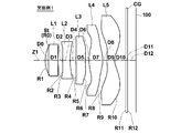
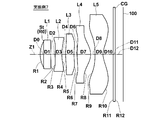
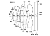
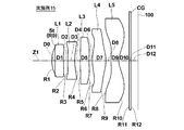
- FIG. 1 is a lens cross-sectional view illustrating a first configuration example of an imaging lens according to an embodiment of the present invention and corresponding to Example 1.
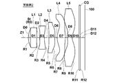
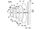
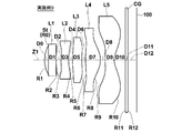
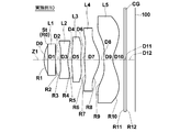
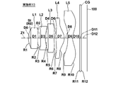
- FIG. FIG. 2 is a lens cross-sectional view illustrating a second configuration example of an imaging lens according to an embodiment of the present invention and corresponding to Example 2; 3 is a lens cross-sectional view illustrating a third configuration example of an imaging lens according to an embodiment of the present invention and corresponding to Example 3.
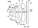
- FIG. 4 is a lens cross-sectional view illustrating a fourth configuration example of an imaging lens according to an embodiment of the present invention and corresponding to Example 4;
- FIG. 5 is a lens cross-sectional view illustrating a fifth configuration example of an imaging lens according to an embodiment of the present invention and corresponding to Example 5.
- FIG. 1 is a lens cross-sectional view illustrating a first configuration example of an imaging lens according to an embodiment of the present invention and corresponding to Example 1.
- FIG. FIG. 2 is a lens cross-sectional view illustrating a second configuration
- FIG. 6 is a lens cross-sectional view illustrating a sixth configuration example of an imaging lens according to an embodiment of the present invention and corresponding to Example 6.
- FIG. 7 is a lens cross-sectional view illustrating a seventh configuration example of an imaging lens according to an embodiment of the present invention and corresponding to Example 7.
- FIG. 8 shows an eighth configuration example of the imaging lens according to an embodiment of the present invention, and is a lens cross-sectional view corresponding to Example 8.
- FIG. 9 is a lens cross-sectional view illustrating a ninth configuration example of an imaging lens according to an embodiment of the present invention and corresponding to Example 9.
- FIG. 10 is a lens cross-sectional view illustrating a tenth configuration example of an imaging lens according to an embodiment of the present invention and corresponding to Example 10.
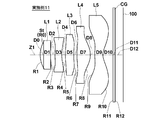
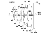
- FIG. 11 shows an eleventh configuration example of the imaging lens according to the embodiment of the invention, and is a lens cross-sectional view corresponding to Example 11.
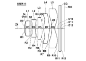
- FIG. 12 is a lens cross-sectional view illustrating a twelfth configuration example of an imaging lens according to an embodiment of the present invention and corresponding to Example 12.
- FIG. 14 is a lens cross-sectional view illustrating a thirteenth configuration example of an imaging lens according to an embodiment of the present invention and corresponding to Example 13.
- FIG. 4A and 4B are aberration diagrams illustrating various aberrations of the imaging lens according to Example 1 of the present invention, in which (A) shows spherical aberration, (B) shows astigmatism (field curvature), and (C) shows distortion.
- FIG. 1 shows spherical aberration
- B shows astigmatism (field curvature)
- C shows distortion.
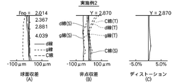
- FIG. 6 is an aberration diagram showing various aberrations of the imaging lens according to Example 2 of the present invention, in which (A) shows spherical aberration, (B) shows astigmatism (field curvature), and (C) shows distortion.
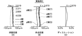
- FIG. 6 is an aberration diagram showing various aberrations of the imaging lens according to Example 3 of the present invention, in which (A) shows spherical aberration, (B) shows astigmatism (field curvature), and (C) shows distortion.
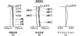
- It is an aberration diagram which shows the various aberrations of the imaging lens which concerns on Example 4 of this invention, (A) shows spherical aberration, (B) shows astigmatism (field curvature), (C) shows distortion aberration.
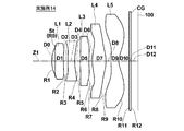
- FIG. 14 is a lens cross-sectional view illustrating a fourteenth configuration example of an imaging lens according to an embodiment of the present invention and corresponding to Example 14.
- FIG. 15 shows a fifteenth configuration example of the imaging lens according to the embodiment of the invention, and is a lens cross-sectional view corresponding to Example 15.
- FIG. FIG. 15 shows a fifteenth configuration example of the imaging lens according to the embodiment of the invention, and is a lens cross-sectional view corresponding to Example 15.
- FIG. 16 is a lens cross-sectional view illustrating a sixteenth configuration example of an imaging lens according to an embodiment of the present invention and corresponding to Example 16; 17 is a lens cross-sectional view illustrating a seventeenth configuration example of an imaging lens according to an embodiment of the present invention and corresponding to Example 17.
- FIG. 18 is an lens configuration diagram illustrating Example 18 of the imaging lens according to an embodiment of the present invention and corresponding to Example 18.
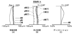
- FIG. It is an aberration diagram which shows the various aberrations of the imaging lens which concerns on Example 14 of this invention, (A) shows spherical aberration, (B) shows astigmatism (field curvature), (C) shows distortion aberration.
- FIG. 1 shows a first configuration example of an imaging lens according to the first embodiment of the present invention.
- This configuration example corresponds to the lens configuration of a first numerical example (Tables 1 and 14) described later.
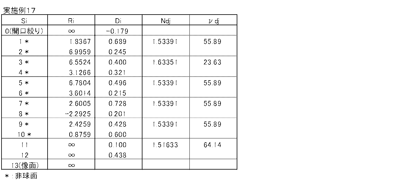
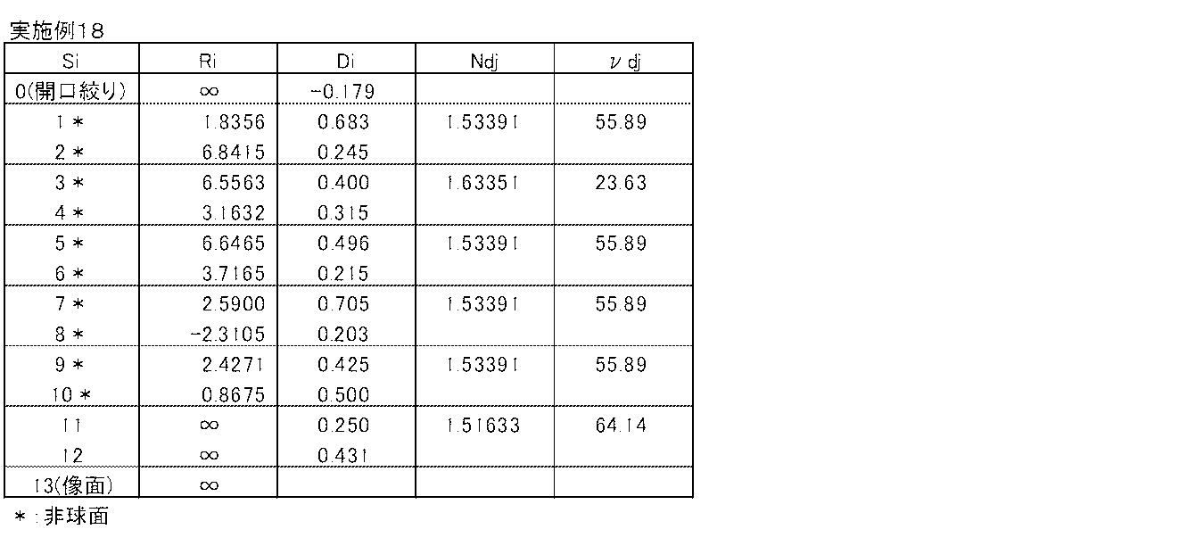
- configurations according to second to eighteenth embodiments corresponding to lens configurations of second to eighteenth numerical examples (Tables 2 to 13, Tables 15 to 26, and Tables 28 to 37) described later.
- Examples of cross-sectional configurations are shown in FIGS. 2 to 13 and FIGS. 29 to 33.
- the radius of curvature of the i-th surface is shown.
- the symbol Di indicates the surface interval on the optical axis Z1 between the i-th surface and the i + 1-th surface. Since the basic configuration is the same in each configuration example, the configuration example of the imaging lens shown in FIG. 1 will be basically described below, and FIG. 2 to FIG. 13 and FIG. 29 to FIG. A configuration example 33 is also described.
- the imaging lens L includes various imaging devices using imaging elements such as CCDs and CMOSs, in particular, relatively small portable terminal devices such as digital still cameras, mobile phones with cameras, smartphones, tablet terminals, and the like. It is suitable for use in PDAs and the like.
- the imaging lens L includes a first lens L1, a second lens L2, a third lens L3, a fourth lens L4, and a fifth lens L5 in order from the object side along the optical axis Z1. Yes.
- FIG. 27 shows an overview of a mobile phone terminal that is the imaging apparatus 1 according to the present embodiment.
- the imaging apparatus 1 according to the present embodiment includes an imaging lens L according to the present embodiment and an imaging element 100 such as a CCD that outputs an imaging signal corresponding to an optical image formed by the imaging lens L (see FIG. 1). ).
- the image sensor 100 is disposed on the imaging surface (imaging surface) of the imaging lens L.
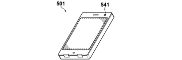
- FIG. 28 shows an overview of a smartphone that is the imaging device 501 according to the embodiment of the present invention.
- An image pickup apparatus 501 according to the embodiment of the present invention includes an image pickup lens L according to this embodiment and an image pickup device 100 such as a CCD that outputs an image pickup signal corresponding to an optical image formed by the image pickup lens L (see FIG. 1)).
- the image sensor 100 is disposed on the imaging surface (imaging surface) of the imaging lens L.
- Various optical members CG may be arranged between the fifth lens L5 and the image sensor 100 according to the configuration on the camera side where the lens is mounted.
- a flat optical member such as a cover glass for protecting the imaging surface or an infrared cut filter may be disposed.
- a flat cover glass provided with a coating having a filter effect such as an infrared cut filter or an ND filter may be used.
- the fifth lens L5 may be coated to have the same effect as the optical member CG. Thereby, the number of parts can be reduced and the total length can be shortened.
- the imaging lens L also has an aperture stop St.
- the aperture stop St is an optical aperture stop, and is preferably disposed before and after the first lens L1.
- the aperture stop St is a so-called “front stop” disposed on the most object side.
- the “front stop” means that the position of the aperture stop in the optical axis direction is at the same position as the intersection of the axial marginal ray and the object side surface of the first lens L1 or closer to the object side. .
- the lenses of the first to eighteenth configuration examples are configuration examples corresponding to the front diaphragm.
- This imaging lens L uses an aspherical surface on at least one surface of each of the first lens L1 to the fifth lens L5 for high performance.
- the first lens L1 has a positive power in the vicinity of the optical axis.
- the object side surface of the first lens L1 has a meniscus shape with a convex surface facing the object side in the vicinity of the optical axis.
- the second lens L2 has negative power in the vicinity of the optical axis.
- the second lens L2 has a concave surface facing the image side in the vicinity of the optical axis. Thereby, it is possible to easily correct the longitudinal chromatic aberration.
- the third lens L3 has negative power in the vicinity of the optical axis.
- the third lens L3 preferably has a shape in the vicinity of the optical axis that has negative power near the center and a peripheral portion that has positive power.
- the third lens L3 has a concave surface facing the image side in the vicinity of the optical axis, and has a shape having a curvature different from that in the vicinity of the optical axis in the peripheral portion.
- the peripheral part of the 3rd lens L3 here means a radial direction outer side from about 40% of the maximum effective radii.
- the third lens L3 has a convex surface facing the object side in the vicinity of the optical axis. As a result, the overall length can be favorably shortened. In order to further enhance this effect, it is preferable that the third lens L3 has a meniscus shape with a convex surface facing the object side.
- the fourth lens L4 has a positive power in the vicinity of the optical axis, and has a convex surface facing the object side in the vicinity of the optical axis.
- the overall length can be shortened suitably.
- the fifth lens L5 has negative power in the vicinity of the optical axis.
- the fifth lens L5 has a concave surface facing the image side in the vicinity of the optical axis.
- the Abbe number ⁇ d2 regarding the d-line of the second lens L2 preferably satisfies the following conditional expression (1). ⁇ d2 ⁇ 35 (1) If the second lens L2 exceeds the upper limit of conditional expression (1), axial chromatic aberration will increase. For this reason, on the second lens L2, the conditional expression (1) is satisfied, the Abbe number ⁇ d2 is reduced, and the dispersion as a negative lens is increased, whereby the axial chromatic aberration can be corrected well.
- the Abbe number ⁇ d2 related to the d-line of the second lens L2 preferably satisfies the following conditional expression (1-1), and satisfies the following conditional expression (1-2): More preferably.
- the Abbe number ⁇ d2 related to the d-line of the second lens L2 further satisfies the following conditional expression (1-3): Preferably it is. This is because when the lower limit of conditional expression (1-3) is exceeded, it is difficult to balance axial chromatic aberration and lateral chromatic aberration. ⁇ d2 ⁇ 30 (1-1) ⁇ d2 ⁇ 25 (1-2) 20 ⁇ d2 (1-3)
- the Abbe number ⁇ d5 regarding the d-line of the fifth lens L5 satisfies the following conditional expression (2). 50 ⁇ d5 (2)
- the conditional expression (2) is satisfied for the fifth lens L5, the Abbe number ⁇ d5 is increased, and the dispersion is reduced, thereby suppressing the deterioration of the lateral chromatic aberration at the periphery of the imaging region and favorably achieving the lateral chromatic aberration. Can be corrected.
- the Abbe number ⁇ d2 regarding the d-line of the second lens L2 satisfies the following conditional expression (2-1), and satisfies the following conditional expression (2-2): More preferably. 53 ⁇ d5 (2-1) 55 ⁇ d5 (2-2)
- the focal length f1 of the first lens L1 and the focal length f4 of the fourth lens L2 satisfy the following conditional expression (3). f4 / f1 ⁇ 1 (3) If the upper limit of conditional expression (3) is exceeded, the total length becomes long, and shortening of the total length becomes difficult. For this reason, when the focal lengths of the first lens L1 and the fourth lens L4 satisfy the conditional expression (3), the overall length can be shortened while maintaining good optical performance. In order to further enhance this effect, it is more preferable that the following conditional expression (3-1) is satisfied, and it is more preferable that the following conditional expression (3-2) is satisfied.
- the focal length f1 of the first lens L1 and the focal distance f4 of the fourth lens L4 are as follows: More preferably, 3) is satisfied. This is because if the lower limit of conditional expression (3-3) is not reached, it is difficult to correct curvature of field. f4 / f1 ⁇ 0.80 (3-1) f4 / f1 ⁇ 0.60 (3-2) 0.20 ⁇ f4 / f1 (3-3)
- the focal length f2 of the second lens L2 and the focal length f3 of the third lens L3 satisfy the following conditional expression (4). 0.50 ⁇ f3 / f2 (4) If the lower limit of conditional expression (4) is not reached, axial chromatic aberration will increase. For this reason, when the relationship between the focal lengths of the second lens L2 and the third lens L3 satisfies the condition of the expression (4), deterioration of axial chromatic aberration is suppressed, and axial chromatic aberration is corrected more favorably. be able to.
- the focal length relationship between the second lens L2 and the third lens L3 preferably satisfies the following conditional expression (4-1), and the following conditional expression (4-2) Is more preferable. 0.70 ⁇ f3 / f2 (4-1) 0.80 ⁇ f3 / f2 (4-2)
- the focal length f of the entire system and the focal length f1 of the first lens L1 satisfy the following conditional expression (5).
- conditional expression (5) 0.5 ⁇ f / f1 ⁇ 1 (5) If the lower limit of conditional expression (5) is not reached, the refractive power of the first lens L1 is too weak with respect to the refractive power of the entire system, making it difficult to shorten the overall length. If the upper limit of conditional expression (5) is exceeded, the refractive power of the first lens L1 is too strong for the refractive power of the entire system, and it becomes difficult to correct spherical aberration, and it is difficult to realize a small F number. It becomes.
- conditional expression (5) it is possible to realize a small F number and correct spherical aberration favorably while shortening the overall length.
- conditional expression (5-1) it is more preferable that the conditional expression (5-1) is satisfied. 0.6 ⁇ f / f1 ⁇ 0.95 (5-1)
- the focal length f of the entire system and the focal length f2 of the second lens L2 satisfy the following conditional expression (6). -0.8 ⁇ f / f2 ⁇ -0.1 (6) If the lower limit of conditional expression (6) is not reached, the refractive power of the second lens L2 is too strong for the refractive power of the entire system, making it difficult to correct longitudinal chromatic aberration. If the upper limit of conditional expression (6) is exceeded, the refractive power of the second lens L2 is too weak with respect to the refractive power of the entire system, making it difficult to shorten the overall length.
- conditional expression (6) it is possible to satisfactorily correct axial chromatic aberration while favorably shortening the overall length.
- conditional expression (6-1) it is more preferable that the conditional expression (6-1) is satisfied. ⁇ 0.65 ⁇ f / f2 ⁇ 0.15 (6-1)
- the focal length f of the entire system and the focal length f3 of the third lens L3 satisfy the following conditional expression (7). -0.6 ⁇ f / f3 ⁇ 0 (7) If the lower limit of conditional expression (7) is not reached, the refractive power of the third lens L3 is too strong for the refractive power of the entire system, making it difficult to shorten the overall length. In addition, it is difficult to correct both axial chromatic aberration and lateral chromatic aberration in a balanced manner. If the upper limit of conditional expression (7) is exceeded, the refractive power of the third lens L3 is too weak with respect to the refractive power of the entire system, making it difficult to correct chromatic aberration of magnification.
- conditional expression (7) it is possible to satisfactorily correct both longitudinal chromatic aberration and lateral chromatic aberration while shortening the overall length.
- conditional expression (7-1) it is more preferable that the conditional expression (7-1) is satisfied. -0.5 ⁇ f / f3 ⁇ 0 (7-1)
- the focal length f of the entire system and the focal length f4 of the fourth lens L4 satisfy the following conditional expression (8). 1 ⁇ f / f4 ⁇ 2.7 (8) If the lower limit of conditional expression (8) is not reached, the refractive power of the fourth lens L4 is too weak with respect to the refractive power of the entire system, making it difficult to shorten the overall length. If the upper limit of conditional expression (8) is exceeded, the refractive power of the fourth lens L4 is too strong for the refractive power of the entire system, and it becomes difficult to correct curvature of field and lateral chromatic aberration.
- conditional expression (8) it is possible to satisfactorily correct the curvature of field and the chromatic aberration of magnification while shortening the overall length.
- the focal length f of the entire system and the focal length f4 of the fourth lens L4 satisfy the conditional expression (8-1). 1.2 ⁇ f / f4 ⁇ 2.3 (8-1)
- the focal length f of the entire system and the focal length f5 of the fifth lens L5 satisfy the following conditional expression (9). -2.2 ⁇ f / f5 ⁇ -0.8 (9) If the lower limit of conditional expression (9) is not reached, the refractive power of the fifth lens L5 is too strong for the refractive power of the entire system, and the field curvature tends to be overcorrected. In addition, the telecentricity is deteriorated, the incident angle of the light beam to the periphery of the image sensor is likely to be excessive, and the conversion efficiency in the periphery of the image sensor is likely to be reduced and color mixture is likely to occur.
- conditional expression (9) If the upper limit of conditional expression (9) is exceeded, the refractive power of the fifth lens L5 is too weak with respect to the refractive power of the entire system, and the field curvature tends to be undercorrected. For this reason, the field curvature can be favorably corrected by satisfying conditional expression (7).
- conditional expression (7) since telecentricity can be suitably maintained and an increase in the incident angle of light rays on the periphery of the image sensor can be suppressed, problems such as a decrease in conversion efficiency and color mixing at the periphery of the image sensor are unlikely to occur. In order to further enhance this effect, it is more preferable to satisfy the conditional expression (9-1). -2.1 ⁇ f / f5 ⁇ -1 (9-1)
- conditional expression (10) -0.1 ⁇ (R3-R4) / (R3 + R4) ⁇ 0.6 (10) If the lower limit of conditional expression (10) is not reached, astigmatism tends to increase. If the upper limit of conditional expression (10) is exceeded, it will be difficult to correct spherical aberration. For this reason, astigmatism and spherical aberration can be satisfactorily corrected by satisfying conditional expression (10).
- the curvature radius R3 of the object side surface of the second lens L2 and the curvature radius R4 of the image side satisfy the following conditional expressions. 0.15 ⁇ (R3-R4) / (R3 + R4) ⁇ 0.55 (10-1)
- conditional expression (11) 0 ⁇ (R5-R6) / (R5 + R6) ⁇ 0.65 (11-1)
- the imaging lens L since the configuration of each lens element is optimized in the lens configuration of five as a whole, a small F-number is achieved while shortening the overall length. In particular, it is possible to realize a lens system in which on-axis and lateral chromatic aberrations are favorably corrected and a high imaging performance from the central field angle to the peripheral field angle is achieved.
- the production suitability is good and higher imaging performance can be realized.
- the imaging signal corresponding to the optical image formed by the high-performance imaging lens L according to the present embodiment is output.
- a high-resolution captured image can be obtained up to the angle of view.
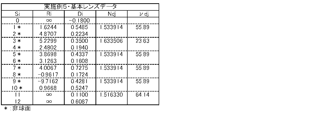
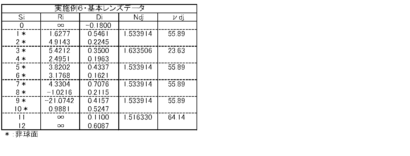
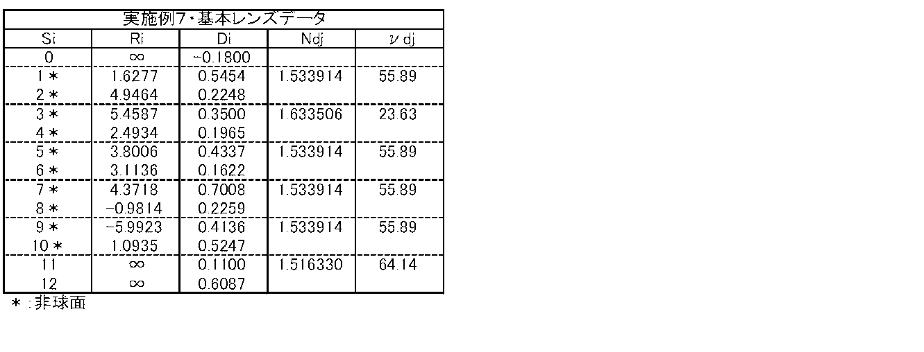
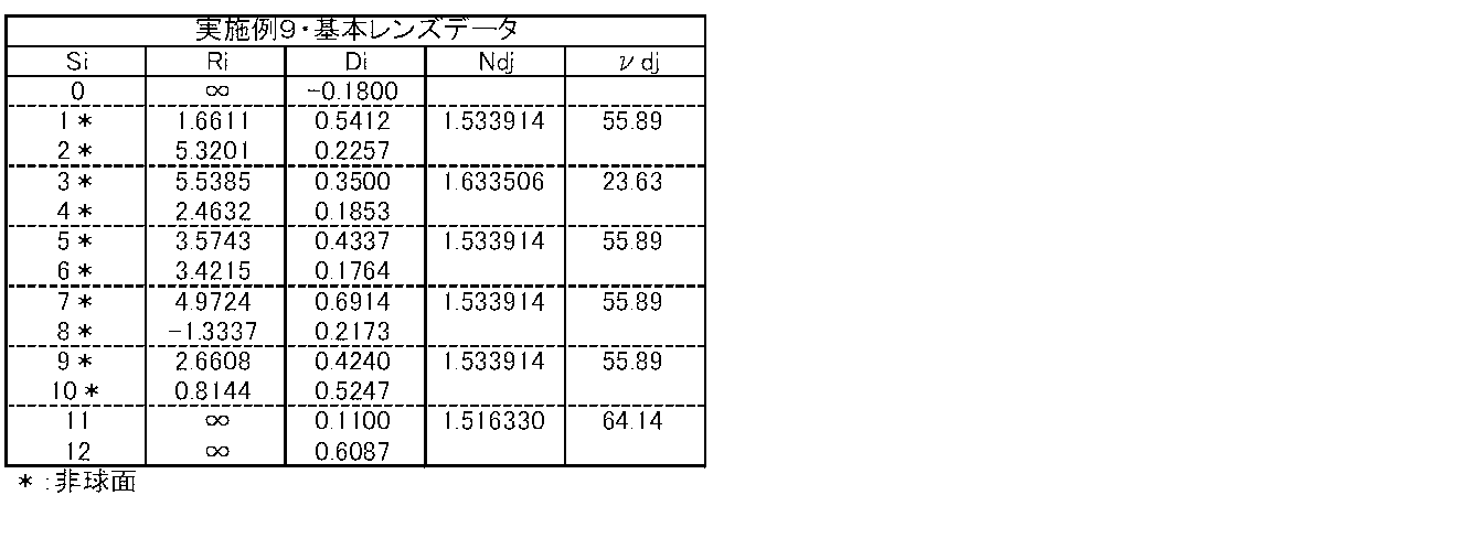
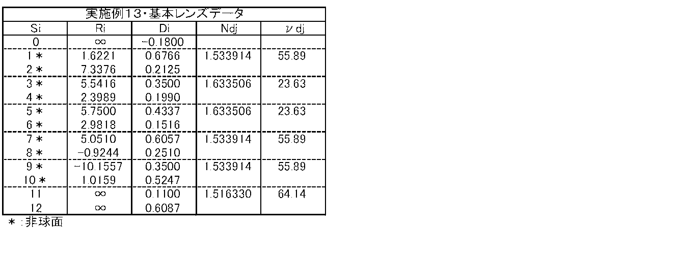
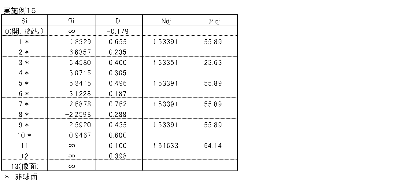
- Table 1 and Table 14 below show specific lens data corresponding to the configuration of the imaging lens shown in FIG.
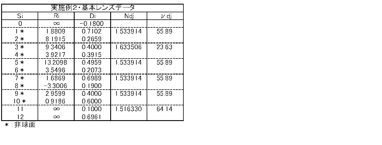
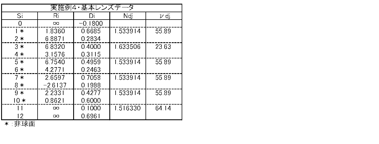
- Table 1 shows basic lens data
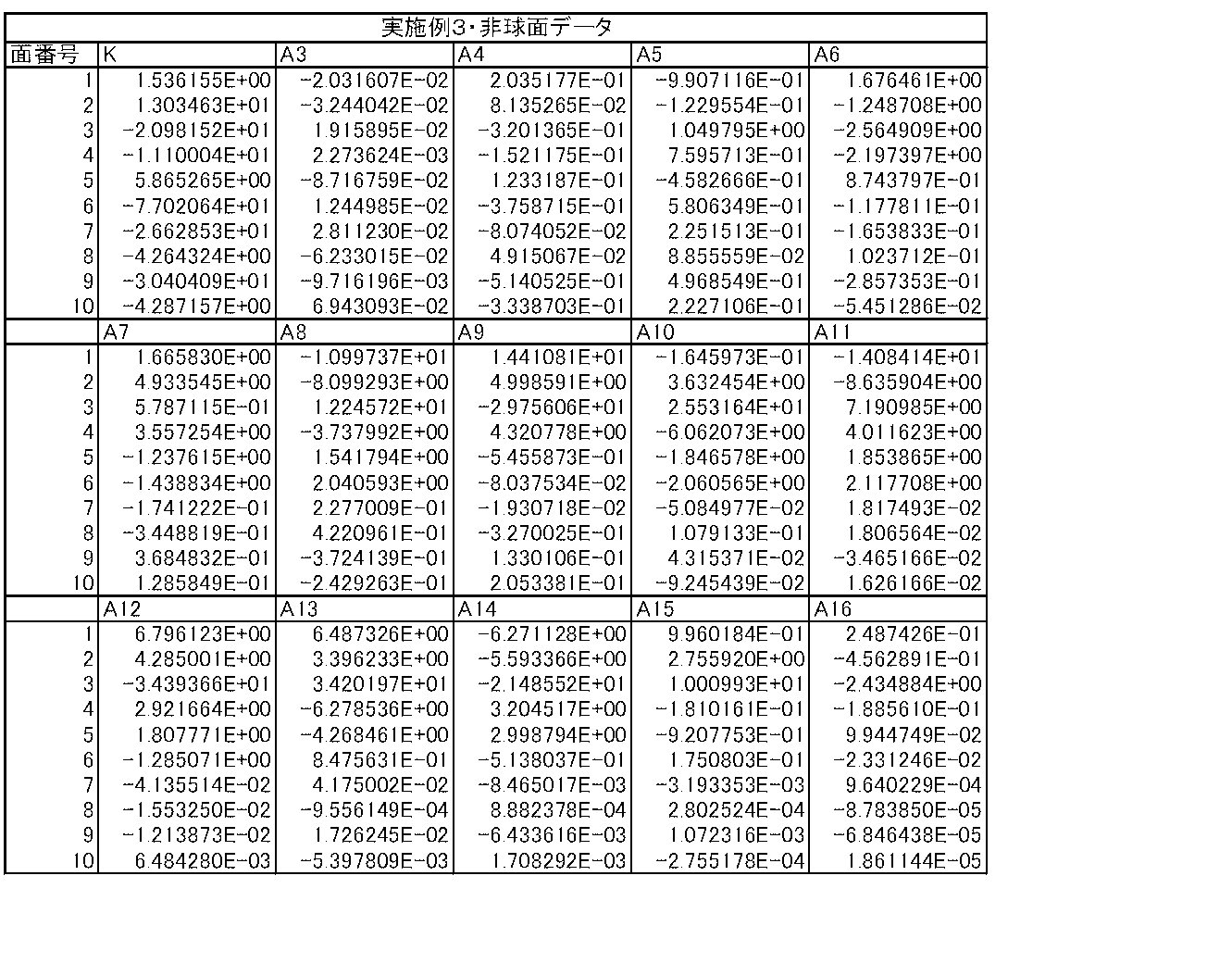
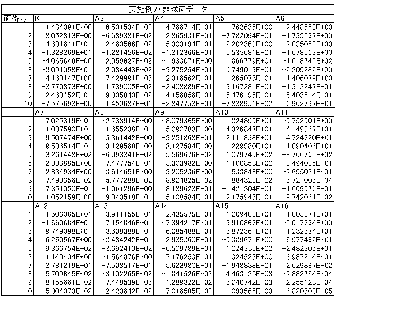
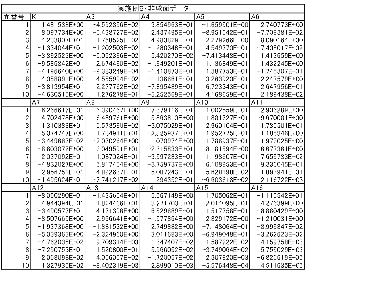
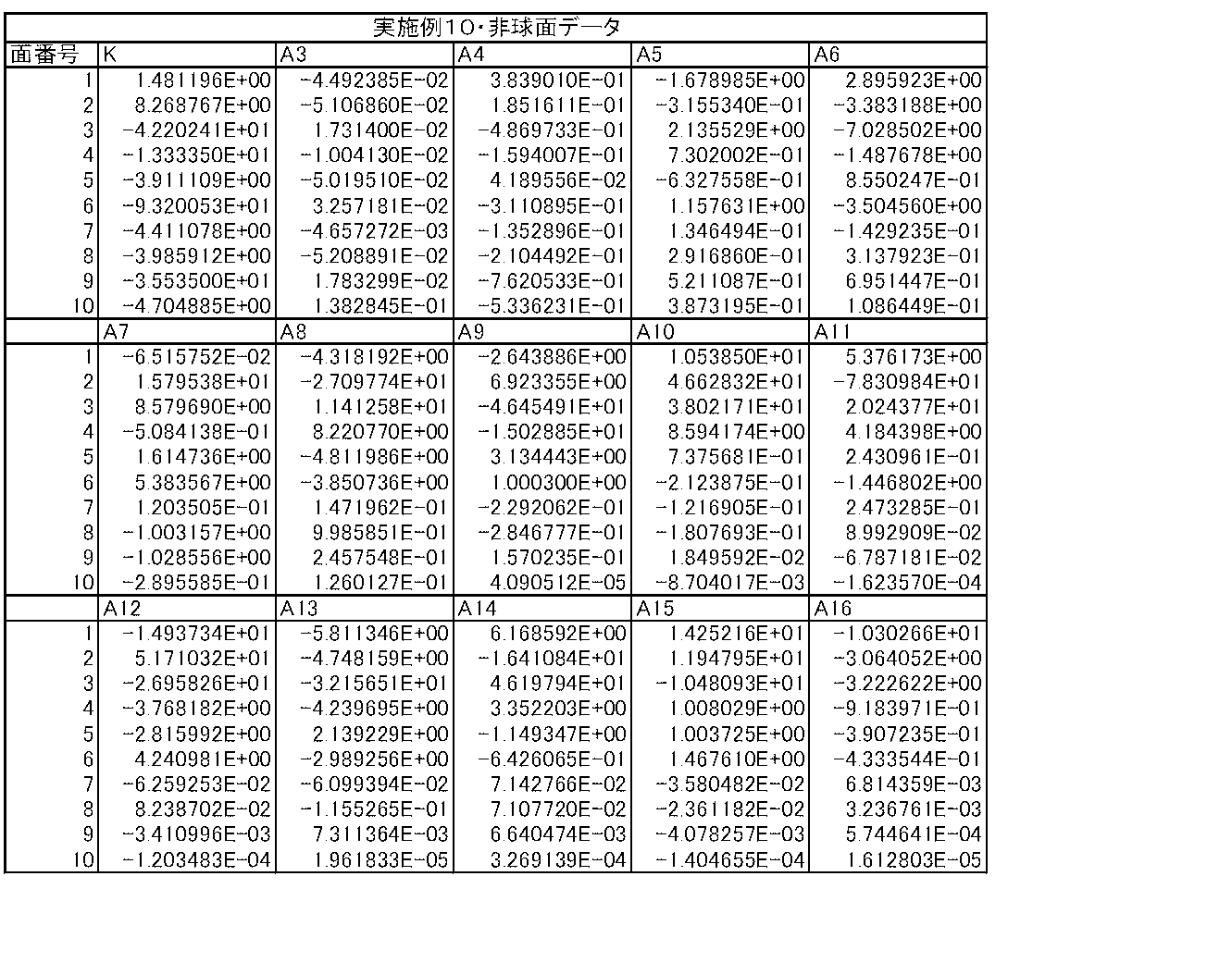
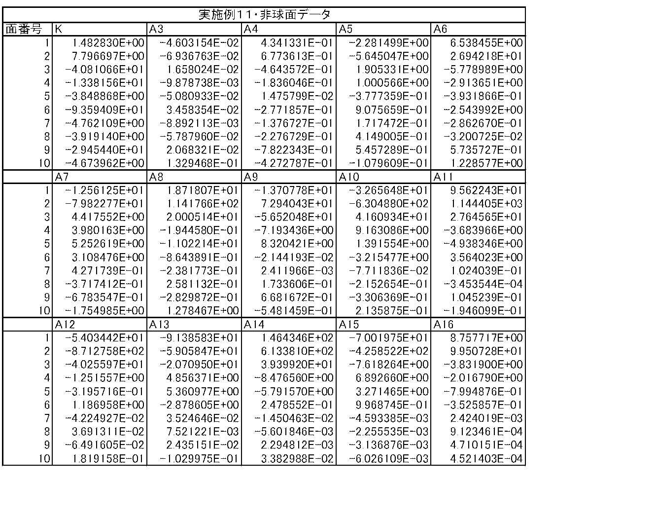
- Table 14 shows data related to aspheric surfaces.
- the surface of the lens element closest to the object side is the first (aperture stop St is the 0th) and heads toward the image side.
- the value (mm) of the curvature radius of the i-th surface from the object side is shown in correspondence with the reference symbol Ri in FIG.
- the column of the surface interval Di indicates the interval (mm) on the optical axis between the i-th surface Si and the i + 1-th surface Si + 1 from the object side.
- the column Ndj the value of the refractive index for the d-line (587.56 nm) of the j-th optical element from the object side is shown.
- the column of ⁇ dj shows the Abbe number value for the d-line of the j-th optical element from the object side.
- both surfaces of the first lens L2 to the fifth lens L5 are all aspherical.
- the basic lens data in Table 1 shows the numerical value of the radius of curvature near the optical axis (paraxial radius of curvature) as the radius of curvature of these aspheric surfaces.
- Table 14 shows aspherical data in the imaging lens of Example 1.
- E indicates that the subsequent numerical value is a “power exponent” with a base of 10
- the numerical value represented by an exponential function with the base of 10 is Indicates that the value before “E” is multiplied.
- “1.0E-02” indicates “1.0 ⁇ 10 ⁇ 2 ”.
- Z is the length (mm) of a perpendicular line drawn from a point on the aspheric surface at a height h from the optical axis to the tangential plane (plane perpendicular to the optical axis) of the apex of the aspheric surface.
- Z C ⁇ h 2 / ⁇ 1+ (1 ⁇ K ⁇ C 2 ⁇ h 2 ) 1/2 ⁇ + ⁇ Ai ⁇ h i (A)
- Z Depth of aspheric surface (mm)
- h Distance from the optical axis to the lens surface (height) (mm)
- C: Paraxial curvature 1 / R (R: paraxial radius of curvature)
- K aspheric coefficient
- Table 2 and Table 15 show specific lens data corresponding to the configuration of the imaging lens shown in FIG. 2 as Example 2 in the same manner as the imaging lens of Example 1 described above.
- specific lens data corresponding to the configuration of the imaging lens shown in FIGS. 3 to 13 are shown in Tables 3 to 13 and Tables 16 to 26 as Example 3 to Example 13, respectively.
- specific lens data corresponding to the configuration of the imaging lens shown in FIGS. 29 to 33 is shown in Tables 28 to 32 and Tables 33 to 37 as Examples 14 to 18.
- both surfaces of the first lens L1 to the fifth lens L5 are all aspherical.
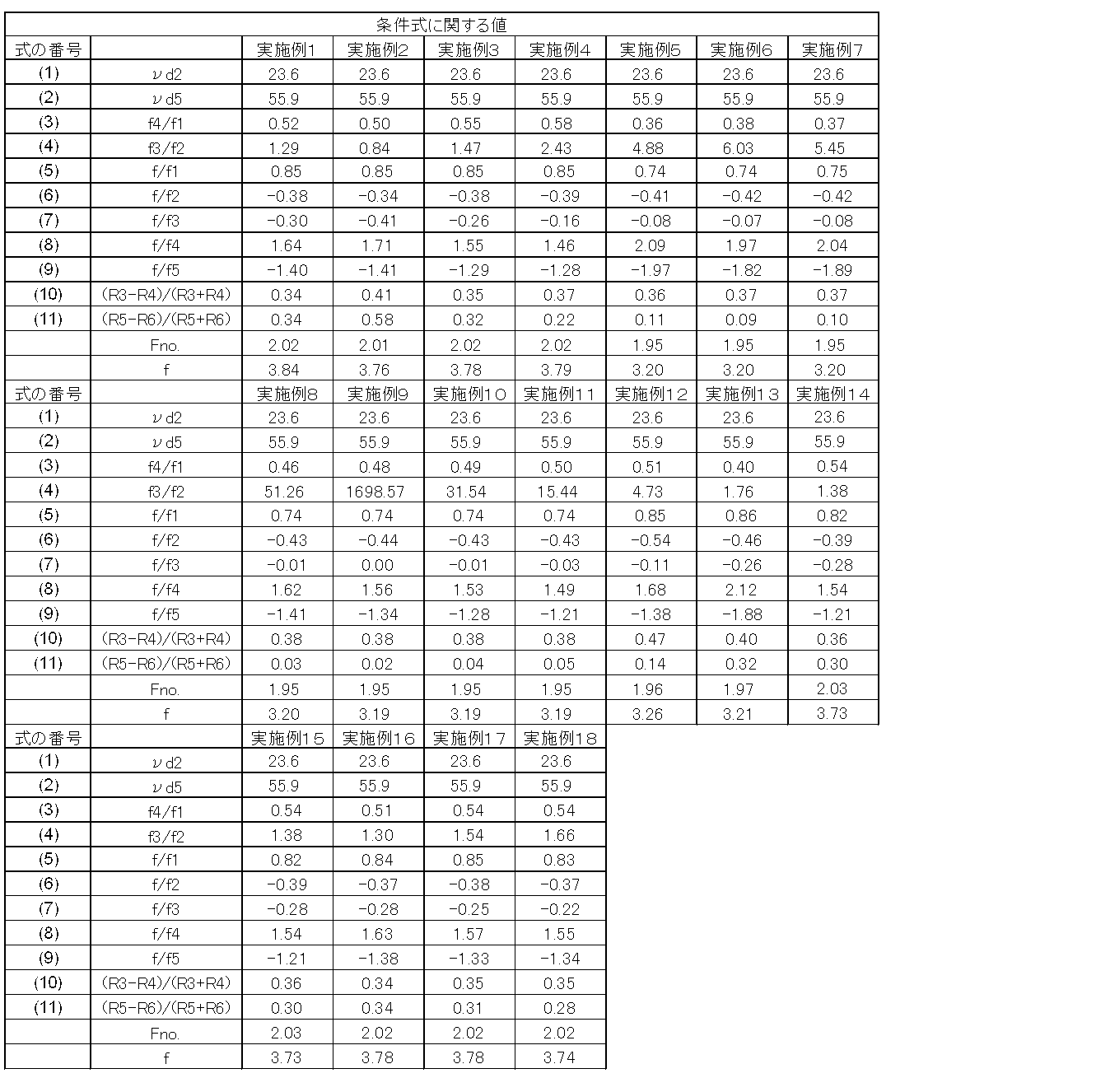
- Table 27 shows values relating to the conditional expressions described above for each example.
- the focal length f (mm) of the entire system In the lens data of each of the above examples described in Tables 1 to 18 below, mm is used as the unit of length. However, since the optical system can be used with proportional enlargement or reduction, other appropriate values can be used. Various units can also be used.
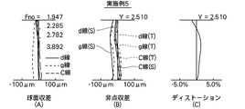
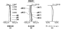
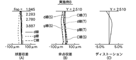
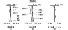
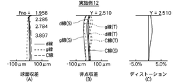
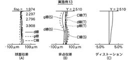
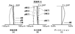
- each aberration diagram shows the aberration with the d-line (wavelength 587.56 nm) as the reference wavelength.
- the spherical aberration diagram and the astigmatism diagram also show aberrations for the g-line (wavelength 435.83 nm) and the C-line (wavelength 656.27 nm).
- the solid line indicates the sagittal direction (S)
- the broken line indicates the tangential direction (T).
- Fno Indicates the F number
- Y indicates the image height (Y).
- each embodiment achieves high imaging performance as well as shortening the overall length.
- this invention is not limited to the said embodiment and each Example, Various deformation
- the values of the radius of curvature, the surface interval, the refractive index, the Abbe number, and the aspheric coefficient of each lens component are not limited to the values shown in the above numerical examples, and may take other values.
- the description is based on the premise that the fixed focus is used.
- the entire lens system can be extended, or a part of the lenses can be moved on the optical axis to enable autofocusing.
Landscapes
- Physics & Mathematics (AREA)
- General Physics & Mathematics (AREA)
- Optics & Photonics (AREA)
- Lenses (AREA)
Abstract
Description
Metal Oxide Semiconductor)等の撮像素子上に被写体の光学像を結像させる撮像レンズ、およびその撮像レンズを搭載して撮影を行うデジタルスチルカメラやカメラ付き携帯電話機、スマートフォン、タブレット端末および情報携帯端末(PDA:Personal Digital Assistance)等の撮像装置に関する。
νd2<35 (1)
50<νd5 (2)
f4/f1<1 (3)
0.50<f3/f2 (4)
0.70<f3/f2 (4-1)
0.5<f/f1<1 (5)
0.6<f/f1<0.95 (5-1)
-0.8<f/f2<-0.1 (6)
-0.65<f/f2<-0.15 (6-1)
-0.6<f/f3<0 (7)
-0.5<f/f3<0 (7-1)
1<f/f4<2.7 (8)
1.2<f/f4<2.3 (8-1)
-2.2<f/f5<-0.8 (9)
-2.1<f/f5<-1 (9-1)
-0.1<(R3-R4)/(R3+R4)<0.6 (10)
-0.1<(R5-R6)/(R5+R6)<0.7 (11)
ただし、
νd2:第2レンズのd線に関するアッベ数
νd5:第5レンズのd線に関するアッベ数
f:全系における焦点距離
f1:第1レンズの焦点距離
f2:第2レンズの焦点距離
f3:第3レンズの焦点距離
f4:第4レンズの焦点距離
f5:第5レンズの焦点距離
R3:第2レンズの物体側の面の近軸曲率半径
R4:第2レンズの像側の面の近軸曲率半径
R5:第3レンズの物体側の面の近軸曲率半径
R6:第3レンズの像側の面の近軸曲率半径
とする。
νd2<35 (1)
第2レンズL2が条件式(1)の上限を上回ると軸上色収差が増大してしまう。このため、第2レンズL2に関して条件式(1)を満足してアッベ数νd2を小さくし、負レンズとしての分散を大きくすることで、軸上の色収差の補正を良好に行うことができる。また、この効果をさらに高めるために、第2レンズL2のd線に関するアッベ数νd2は、下記条件式(1-1)を満たしていることがより好ましく、下記条件式(1-2)を満たしていることがさらに好ましい。また、第2レンズL2のd線に関するアッベ数νd2は、条件式(1)、(1-1)、(1-2)のいずれかに加え、下記条件式(1-3)をさらに満たしていることが好ましい。条件式(1-3)の下限を超えた場合には、軸上色収差と倍率色収差のバランスが取りづらくなるためである。
νd2<30 (1-1)
νd2<25 (1-2)
20<νd2 (1-3)
50<νd5 (2)
第5レンズL5が条件式(2)の下限を下回ると、結像領域周辺部の倍率色収差の増大を招いてしまう。このため、第5レンズL5関して条件式(2)を満足してアッベ数νd5を大きくし、分散を小さくすることで、結像領域周辺部の倍率色収差の劣化を抑制し、良好に倍率色収差の補正を行うことができる。また、この効果をさらに高めるために、第2レンズL2のd線に関するアッベ数νd2が、下記条件式(2-1)を満たしていることがより好ましく、下記条件式(2-2)を満たしていることがさらに好ましい。
53<νd5 (2-1)
55<νd5 (2-2)
f4/f1<1 (3)
条件式(3)の上限を上回ると全長が長くなり、全長の短縮化が困難になる。このため、第1レンズL1と第4レンズL4の焦点距離を、条件式(3)を満足するようにすることにより、良好な光学性能を保持しながら全長を短縮することができる。また、この効果をさらに高めるために、下記条件式(3-1)を満たしていることがより好ましく、下記条件式(3-2)を満たしていることがさらに好ましい。また、第1レンズL1の焦点距離f1と第4レンズL4の焦点距離f4は、条件式(3)、(3-1)、(3-2)のいずれかに加え、下記条件式(3-3)を満たしていることがさらに好ましい。上記条件式(3-3)の下限を下回ると、像面湾曲の補正が難しくなりやすいためである。
f4/f1<0.80 (3-1)
f4/f1<0.60 (3-2)
0.20<f4/f1 (3-3)
0.50<f3/f2 (4)
条件式(4)の下限を下回ると軸上色収差が増大してしまう。このため、第2レンズL2と第3レンズL3の焦点距離の関係が式(4)の条件を満足することで、軸上の色収差の劣化を抑制し、より良好に軸上の色収差を補正することができる。また、この効果をさらに高めるために、第2レンズL2と第3レンズL3の焦点距離の関係が下記条件式(4-1)を満たしていることがより好ましく、下記条件式(4-2)を満たしていることがさらに好ましい。
0.70<f3/f2 (4-1)
0.80<f3/f2 (4-2)
0.5<f/f1<1 (5)
条件式(5)の下限を下回ると、全系の屈折力に対して第1レンズL1の屈折力が弱すぎて、全長の短縮化が困難となる。条件式(5)の上限を上回ると、全系の屈折力に対して第1レンズL1の屈折力が強すぎて、球面収差の補正が難しくなり、また、小さなFナンバーを実現するのが困難となる。このため、条件式(5)を満足することで、全長を短縮化しながらも、小さなFナンバーを実現できるとともに球面収差を良好に補正することができる。また、この効果をさらに高めるために、条件式(5-1)を満たしていることがより好ましい。
0.6<f/f1<0.95 (5-1)
-0.8<f/f2<-0.1 (6)
条件式(6)の下限を下回ると、全系の屈折力に対して第2レンズL2の屈折力が強すぎて、軸上色収差の補正が困難となる。条件式(6)の上限を上回ると、全系の屈折力に対して第2レンズL2の屈折力が弱すぎて、全長の短縮化が困難となる。このため、条件式(6)を満足することで、全長の短縮化を好適に図りつつ、軸上色収差を良好に補正することができる。また、この効果をさらに高めるために、条件式(6-1)を満たしていることがより好ましい。
-0.65<f/f2<-0.15 (6-1)
-0.6<f/f3<0 (7)
条件式(7)の下限を下回ると、全系の屈折力に対して第3レンズL3の屈折力が強すぎて、全長の短縮化が困難となる。また、軸上色収差と倍率の色収差との両方をバランス良く補正することが難しくなる。条件式(7)の上限を上回ると、全系の屈折力に対して第3レンズL3の屈折力が弱すぎて、倍率の色収差の補正が困難となる。このため、条件式(7)を満足することで、全長を短縮化しつつ、軸上色収差と倍率の色収差の両方を良好に補正することができる。また、この効果をさらに高めるために、条件式(7-1)を満たしていることがより好ましい。
-0.5<f/f3<0 (7-1)
1<f/f4<2.7 (8)
条件式(8)の下限を下回ると、全系の屈折力に対して第4レンズL4の屈折力が弱すぎて、全長の短縮化が困難となる。条件式(8)の上限を上回ると、全系の屈折力に対して第4レンズL4の屈折力が強すぎて、像面湾曲と倍率の色収差の補正が困難となる。このため、条件式(8)を満足することで、全長を短縮化しつつ、像面湾曲と倍率の色収差を良好に補正することができる。また、この効果をさらに高めるために、全系の焦点距離fと第4レンズL4の焦点距離f4が条件式(8-1)を満たすことがより好ましい。
1.2<f/f4<2.3 (8-1)
-2.2<f/f5<-0.8 (9)
条件式(9)の下限を下回ると、全系の屈折力に対して第5レンズL5の屈折力が強すぎて、像面湾曲が補正過剰となりやすい。また、テレセントリック性が悪化し、撮像素子周辺部への光線の入射角が過大となりやすく、撮像素子周辺部における変換効率の低下や混色の発生を招きやすい。条件式(9)の上限を上回ると、全系の屈折力に対して第5レンズL5の屈折力が弱すぎて、像面湾曲が補正不足となりやすい。このため、条件式(7)を満足することで、像面湾曲を良好に補正することができる。また、テレセントリック性を好適に維持して、撮像素子周辺部への光線の入射角が大きくなることを抑制できるため、撮像素子周辺部における変換効率の低下や混色の発生の問題が生じにくい。また、この効果をさらに高めるために、条件式(9-1)を満たすことがより好ましい。
-2.1<f/f5<-1 (9-1)
-0.1<(R3-R4)/(R3+R4)<0.6 (10)
条件式(10)の下限を下回ると、非点収差の増大を招きやすい。また、条件式(10)の上限を上回ると、球面収差の補正が困難となる。このため、条件式(10)を満足することで、非点収差および球面収差を良好に補正することができる。特に第2レンズL2の物体側の面の曲率半径R3と像側の曲率半径R4が以下の条件式を満たすことがより好ましい。
0.15<(R3-R4)/(R3+R4)<0.55 (10-1)
-0.1<(R5-R6)/(R5+R6)<0.7 (11)
条件式(11)の下限を下回ると、全長の短縮化が困難となる。条件式(11)の上限を上回ると、非点収差が増大しやすくなる。このため、条件式(11)を満足することで、全長を短縮化しつつ、非点収差を良好に補正することができる。この効果をさらに高めるために、条件式(11-1)をたすことがより好ましい。
0<(R5-R6)/(R5+R6)<0.65 (11-1)
ただし、
Z:非球面の深さ(mm)
h:光軸からレンズ面までの距離(高さ)(mm)
C:近軸曲率=1/R
(R:近軸曲率半径)
Ai:第i次(iは3以上の整数)の非球面係数
K:非球面係数
















Claims (19)
- 物体側から順に、
正のパワーを有し、かつ、物体側に凸面を向けたメニスカス形状であり、少なくとも1面が非球面形状である第1レンズと、
負のパワーを有し、かつ、像側に凹面を向け、少なくとも1面が非球面形状である第2レンズと、
負のパワーを有し、かつ、物体側に凸面を向け、少なくとも1面が非球面形状である第3レンズと、
正のパワーを有し、かつ、物体側に凸面を向け、少なくとも1面が非球面形状の第4レンズと、
負のパワーを有し、かつ、像側に凹面を向け、少なくとも1面が非球面形状の第5レンズから構成される実質的に5個のレンズからなることを特徴とする撮像レンズ。 - さらに以下の条件式を満足することを特徴とする請求項1に記載の撮像レンズ。
f4/f1<1 (3)
ただし、
f1:前記第1レンズの焦点距離
f4:前記第4レンズの焦点距離
とする。 - さらに以下の条件式を満足することを特徴とする請求項1に記載の撮像レンズ。
νd2<35 (1)
50<νd5 (2)
f4/f1<1 (3)
ただし、
νd2:前記第2レンズのd線に関するアッベ数
νd5:前記第5レンズのd線に関するアッベ数
f1:前記第1レンズの焦点距離
f4:前記第4レンズの焦点距離
とする。 - さらに以下の条件式を満足することを特徴とする請求項1から4のいずれか1記載の撮像レンズ。
0.50<f3/f2 (4)
ただし、
f2:前記第2レンズの焦点距離
f3:前記第3レンズの焦点距離
とする。 - 前記第1レンズよりも物体側に絞りを配置したことを特徴とする請求項1から4のいずれか1記載の撮像レンズ。
- さらに以下の条件式を満足することを特徴とする請求項1から5のいずれか1項記載の撮像レンズ。
0.5<f/f1<1 (5)
ただし、
f:全系における焦点距離
f1:前記第1レンズの焦点距離
とする。 - さらに以下の条件式を満足することを特徴とする請求項1から6のいずれかに記載の撮像レンズ。
-0.8<f/f2<-0.1 (6)
ただし、
f:全系における焦点距離
f2:前記第2レンズの焦点距離
とする。 - さらに以下の条件式を満足することを特徴とする請求項1から7のいずれか1項に記載の撮像レンズ。
-0.6<f/f3<0 (7)
ただし、
f:全系における焦点距離
f3:前記第3レンズの焦点距離
とする。 - さらに以下の条件式を満足することを特徴とする請求項1から8のいずれか1項に記載の撮像レンズ。
1<f/f4<2.7 (8)
ただし、
f:全系における焦点距離
f4:前記第4レンズの焦点距離
とする。 - さらに以下の条件式を満足することを特徴とする請求項1から9のいずれか1項に記載の撮像レンズ。
-2.2<f/f5<-0.8 (9)
ただし、
f:全系における焦点距離
f5:前記第5レンズの焦点距離
とする。 - さらに以下の条件式を満足することを特徴とする請求項1から10のいずれか1項に記載の撮像レンズ。
-0.1<(R3-R4)/(R3+R4)<0.6 (10)
ただし、
R3:前記第2レンズの物体側の面の近軸曲率半径
R4:前記第2レンズの像側の面の近軸曲率半径
とする。 - さらに以下の条件式を満足することを特徴とする請求項1から11のいずれか1項に記載の撮像レンズ。
-0.1<(R5-R6)/(R5+R6)<0.7 (11)
ただし、
R5:前記第3レンズの物体側の面の近軸曲率半径
R6:前記第3レンズの像側の面の近軸曲率半径
とする。 - さらに以下の条件式を満足することを特徴とする請求項1から12のいずれか1項記載の撮像レンズ。
0.70<f3/f2 (4-1)
ただし、
f2:前記第2レンズの焦点距離
f3:前記第3レンズの焦点距離
とする。 - さらに以下の条件式を満足することを特徴とする請求項1から13のいずれか1項に記載の撮像レンズ。
0.6<f/f1<0.95 (5-1)
ただし、
f:全系における焦点距離
f1:前記第1レンズの焦点距離
とする。 - さらに以下の条件式を満足することを特徴とする請求項1から14のいずれか1項に記載の撮像レンズ。
-0.65<f/f2<-0.15 (6-1)
ただし、
f:全系における焦点距離
f2:前記第2レンズの焦点距離
とする。 - さらに以下の条件式を満足することを特徴とする請求項1から15のいずれか1項に記載の撮像レンズ。
-0.5<f/f3<0 (7-1)
ただし、
f:全系における焦点距離
f3:前記第3レンズの焦点距離
とする。 - さらに以下の条件式を満足することを特徴とする請求項1から16のいずれか1項に記載の撮像レンズ。
1.2<f/f4<2.3 (8-1)
ただし、
f:全系における焦点距離
f4:前記第4レンズの焦点距離
とする。 - さらに以下の条件式を満足することを特徴とする請求項1から17のいずれか1項に記載の撮像レンズ。
-2.1<f/f5<-1 (9-1)
ただし、
f:全系における焦点距離
f5:前記第5レンズの焦点距離
とする。 - 請求項1に記載された撮像レンズを備えたことを特徴とする撮像装置。
Priority Applications (3)
| Application Number | Priority Date | Filing Date | Title |
|---|---|---|---|
| CN201290000541.9U CN203786375U (zh) | 2011-05-26 | 2012-05-25 | 成像透镜和包括该成像透镜的成像装置 |
| JP2013516221A JP5602299B2 (ja) | 2011-05-26 | 2012-05-25 | 撮像レンズおよび撮像レンズを備えた撮像装置 |
| US14/088,669 US8885269B2 (en) | 2011-05-26 | 2013-11-25 | Imaging lens and imaging apparatus including the imaging lens |
Applications Claiming Priority (4)
| Application Number | Priority Date | Filing Date | Title |
|---|---|---|---|
| JP2011117822 | 2011-05-26 | ||
| JP2011-117822 | 2011-05-26 | ||
| JP2012-118369 | 2012-05-24 | ||
| JP2012118369 | 2012-05-24 |
Related Child Applications (1)
| Application Number | Title | Priority Date | Filing Date |
|---|---|---|---|
| US14/088,669 Continuation US8885269B2 (en) | 2011-05-26 | 2013-11-25 | Imaging lens and imaging apparatus including the imaging lens |
Publications (1)
| Publication Number | Publication Date |
|---|---|
| WO2012160831A1 true WO2012160831A1 (ja) | 2012-11-29 |
Family
ID=47216921
Family Applications (1)
| Application Number | Title | Priority Date | Filing Date |
|---|---|---|---|
| PCT/JP2012/003421 Ceased WO2012160831A1 (ja) | 2011-05-26 | 2012-05-25 | 撮像レンズおよび撮像レンズを備えた撮像装置 |
Country Status (4)
| Country | Link |
|---|---|
| US (1) | US8885269B2 (ja) |
| JP (1) | JP5602299B2 (ja) |
| CN (1) | CN203786375U (ja) |
| WO (1) | WO2012160831A1 (ja) |
Cited By (6)
| Publication number | Priority date | Publication date | Assignee | Title |
|---|---|---|---|---|
| JP2013174741A (ja) * | 2012-02-24 | 2013-09-05 | Hitachi Maxell Ltd | 撮像レンズおよび撮像装置 |
| JP5922854B1 (ja) * | 2016-01-27 | 2016-05-24 | エーエーシー テクノロジーズ ピーティーイー リミテッドAac Technologies Pte.Ltd. | 撮像レンズ |
| JP2021149090A (ja) * | 2020-03-19 | 2021-09-27 | エーエーシー オプティクス (チャンジョウ)カンパニーリミテッド | 撮像光学レンズ |
| KR20220012985A (ko) * | 2021-04-05 | 2022-02-04 | 엘지이노텍 주식회사 | 광학계 및 이를 포함하는 카메라 모듈 |
| JP7026766B1 (ja) | 2020-09-03 | 2022-02-28 | エーエーシー オプティックス (ソシュウ) カンパニーリミテッド | 撮像光学レンズ |
| CN114280757A (zh) * | 2020-09-28 | 2022-04-05 | 大立光电股份有限公司 | 影像镜头、取像装置及电子装置 |
Families Citing this family (14)
| Publication number | Priority date | Publication date | Assignee | Title |
|---|---|---|---|---|
| JP5602305B2 (ja) * | 2011-06-15 | 2014-10-08 | 富士フイルム株式会社 | 撮像レンズおよび撮像レンズを備えた撮像装置 |
| TWI553334B (zh) | 2014-08-27 | 2016-10-11 | 玉晶光電股份有限公司 | 光學成像鏡頭及應用該光學成像鏡頭的電子裝置 |
| TWI589916B (zh) * | 2015-01-06 | 2017-07-01 | 先進光電科技股份有限公司 | 光學成像系統(五) |
| JP5756245B1 (ja) * | 2015-03-13 | 2015-07-29 | エーエーシーアコースティックテクノロジーズ(シンセン)カンパニーリミテッドAAC Acoustic Technologies(Shenzhen)Co.,Ltd | 撮像レンズ |
| JP5807137B1 (ja) * | 2015-07-24 | 2015-11-10 | エーエーシーアコースティックテクノロジーズ(シンセン)カンパニーリミテッドAAC Acoustic Technologies(Shenzhen)Co.,Ltd | 撮像レンズ |
| CN106802467B (zh) * | 2016-12-14 | 2019-05-28 | 瑞声科技(新加坡)有限公司 | 摄像光学镜头 |
| CN106980168B (zh) * | 2016-12-14 | 2019-11-19 | 瑞声科技(新加坡)有限公司 | 摄像光学镜头 |
| TWI639864B (zh) | 2017-02-17 | 2018-11-01 | 大立光電股份有限公司 | 影像擷取光學透鏡組、取像裝置及電子裝置 |
| US10775593B2 (en) * | 2017-11-17 | 2020-09-15 | Aac Communication Technologies (Changzhou) Co., Ltd. | Camera optical lens |
| CN108267863B (zh) * | 2018-01-04 | 2020-11-24 | 中国空空导弹研究院 | 一种紧凑型超分辨成像光学系统 |
| CN110412736B (zh) * | 2019-06-30 | 2021-09-21 | 瑞声光学解决方案私人有限公司 | 摄像光学镜头 |
| WO2022198498A1 (zh) * | 2021-03-24 | 2022-09-29 | 欧菲光集团股份有限公司 | 成像系统、摄像模组及电子设备 |
| KR102523089B1 (ko) * | 2021-04-07 | 2023-04-18 | 재단법인 오송첨단의료산업진흥재단 | 형광 이미징용 초소형 렌즈 시스템 |
| CN116184639B (zh) * | 2023-04-28 | 2023-10-17 | 江西联昊光电有限公司 | 光学镜头及vr设备 |
Citations (5)
| Publication number | Priority date | Publication date | Assignee | Title |
|---|---|---|---|---|
| JPH03138612A (ja) * | 1989-10-25 | 1991-06-13 | Asahi Optical Co Ltd | ソフトフォーカスレンズ |
| JP2008542821A (ja) * | 2005-05-27 | 2008-11-27 | ザ・ボーイング・カンパニー | コンパクトで軽量なデジタルカメラレンズ |
| WO2010024198A1 (ja) * | 2008-08-25 | 2010-03-04 | コニカミノルタオプト株式会社 | 撮像レンズ、撮像装置及び携帯端末 |
| JP2010271689A (ja) * | 2009-04-21 | 2010-12-02 | Fujifilm Corp | 位相補正板、撮像システム、撮像装置、携帯電話、車載機器、監視カメラ、内視鏡装置、デジタルカメラ、デジタルビデオカメラ、およびレンズユニット |
| JP2011164562A (ja) * | 2010-01-13 | 2011-08-25 | Konica Minolta Opto Inc | 撮像レンズ、撮像装置及び携帯端末 |
Family Cites Families (5)
| Publication number | Priority date | Publication date | Assignee | Title |
|---|---|---|---|---|
| JP5201679B2 (ja) | 2008-12-25 | 2013-06-05 | 株式会社オプトロジック | 撮像レンズ |
| JP5095662B2 (ja) | 2009-03-31 | 2012-12-12 | カンタツ株式会社 | 固体撮像素子用撮像レンズ |
| JP5371148B2 (ja) | 2009-06-04 | 2013-12-18 | 株式会社オプトロジック | 撮像レンズ |
| TWI416198B (zh) | 2010-11-19 | 2013-11-21 | Largan Precision Co Ltd | 光學取像系統 |
| TWI422900B (zh) | 2010-12-23 | 2014-01-11 | Largan Precision Co Ltd | 光學攝影鏡頭組 |
-
2012
- 2012-05-25 CN CN201290000541.9U patent/CN203786375U/zh not_active Expired - Lifetime
- 2012-05-25 WO PCT/JP2012/003421 patent/WO2012160831A1/ja not_active Ceased
- 2012-05-25 JP JP2013516221A patent/JP5602299B2/ja not_active Expired - Fee Related
-
2013
- 2013-11-25 US US14/088,669 patent/US8885269B2/en active Active
Patent Citations (5)
| Publication number | Priority date | Publication date | Assignee | Title |
|---|---|---|---|---|
| JPH03138612A (ja) * | 1989-10-25 | 1991-06-13 | Asahi Optical Co Ltd | ソフトフォーカスレンズ |
| JP2008542821A (ja) * | 2005-05-27 | 2008-11-27 | ザ・ボーイング・カンパニー | コンパクトで軽量なデジタルカメラレンズ |
| WO2010024198A1 (ja) * | 2008-08-25 | 2010-03-04 | コニカミノルタオプト株式会社 | 撮像レンズ、撮像装置及び携帯端末 |
| JP2010271689A (ja) * | 2009-04-21 | 2010-12-02 | Fujifilm Corp | 位相補正板、撮像システム、撮像装置、携帯電話、車載機器、監視カメラ、内視鏡装置、デジタルカメラ、デジタルビデオカメラ、およびレンズユニット |
| JP2011164562A (ja) * | 2010-01-13 | 2011-08-25 | Konica Minolta Opto Inc | 撮像レンズ、撮像装置及び携帯端末 |
Cited By (12)
| Publication number | Priority date | Publication date | Assignee | Title |
|---|---|---|---|---|
| JP2013174741A (ja) * | 2012-02-24 | 2013-09-05 | Hitachi Maxell Ltd | 撮像レンズおよび撮像装置 |
| JP5922854B1 (ja) * | 2016-01-27 | 2016-05-24 | エーエーシー テクノロジーズ ピーティーイー リミテッドAac Technologies Pte.Ltd. | 撮像レンズ |
| JP2021149090A (ja) * | 2020-03-19 | 2021-09-27 | エーエーシー オプティクス (チャンジョウ)カンパニーリミテッド | 撮像光学レンズ |
| JP7091432B2 (ja) | 2020-03-19 | 2022-06-27 | エーエーシー オプティクス (チャンジョウ)カンパニーリミテッド | 撮像光学レンズ |
| JP7026766B1 (ja) | 2020-09-03 | 2022-02-28 | エーエーシー オプティックス (ソシュウ) カンパニーリミテッド | 撮像光学レンズ |
| JP2022042935A (ja) * | 2020-09-03 | 2022-03-15 | エーエーシー オプティックス (ソシュウ) カンパニーリミテッド | 撮像光学レンズ |
| CN114280757A (zh) * | 2020-09-28 | 2022-04-05 | 大立光电股份有限公司 | 影像镜头、取像装置及电子装置 |
| CN114280757B (zh) * | 2020-09-28 | 2023-05-02 | 大立光电股份有限公司 | 影像镜头、取像装置及电子装置 |
| US11828910B2 (en) | 2020-09-28 | 2023-11-28 | Largan Precision Co., Ltd. | Image lens assembly, imaging apparatus and electronic device |
| US12117596B2 (en) | 2020-09-28 | 2024-10-15 | Largan Precision Co., Ltd. | Image lens assembly, imaging apparatus and electronic device |
| KR20220012985A (ko) * | 2021-04-05 | 2022-02-04 | 엘지이노텍 주식회사 | 광학계 및 이를 포함하는 카메라 모듈 |
| KR102632840B1 (ko) * | 2021-04-05 | 2024-02-02 | 엘지이노텍 주식회사 | 광학계 및 이를 포함하는 카메라 모듈 |
Also Published As
| Publication number | Publication date |
|---|---|
| US20140078600A1 (en) | 2014-03-20 |
| US8885269B2 (en) | 2014-11-11 |
| CN203786375U (zh) | 2014-08-20 |
| JP5602299B2 (ja) | 2014-10-08 |
| JPWO2012160831A1 (ja) | 2014-07-31 |
Similar Documents
| Publication | Publication Date | Title |
|---|---|---|
| JP5602299B2 (ja) | 撮像レンズおよび撮像レンズを備えた撮像装置 | |
| JP5827688B2 (ja) | 撮像レンズおよび撮像レンズを備えた撮像装置 | |
| JP5823527B2 (ja) | 撮像レンズおよび撮像レンズを備えた撮像装置 | |
| JP5911819B2 (ja) | 撮像レンズおよび撮像レンズを備えた撮像装置 | |
| JP5752850B2 (ja) | 撮像レンズおよび撮像レンズを備えた撮像装置 | |
| JP5886230B2 (ja) | 撮像レンズおよび撮像レンズを備えた撮像装置 | |
| JP5735712B2 (ja) | 撮像レンズおよび撮像レンズを備えた撮像装置 | |
| JP5698872B2 (ja) | 撮像レンズおよび撮像レンズを備えた撮像装置 | |
| JP5687390B2 (ja) | 撮像レンズおよび撮像レンズを備えた撮像装置 | |
| JP5602305B2 (ja) | 撮像レンズおよび撮像レンズを備えた撮像装置 | |
| JP5800438B2 (ja) | 撮像レンズおよび撮像レンズを備えた撮像装置 | |
| JP5785324B2 (ja) | 撮像レンズおよび撮像レンズを備えた撮像装置 | |
| JP5937036B2 (ja) | 撮像レンズおよび撮像レンズを備えた撮像装置 | |
| JP2014240918A (ja) | 撮像レンズおよび撮像レンズを備えた撮像装置 | |
| WO2013114812A1 (ja) | 撮像レンズおよび撮像レンズを備えた撮像装置 | |
| JP2015022145A (ja) | 撮像レンズおよび撮像レンズを備えた撮像装置 | |
| WO2013175783A1 (ja) | 撮像レンズおよび撮像レンズを備えた撮像装置 | |
| WO2014155460A1 (ja) | 撮像レンズおよび撮像レンズを備えた撮像装置 | |
| WO2014155459A1 (ja) | 撮像レンズおよび撮像レンズを備えた撮像装置 | |
| JP5722507B2 (ja) | 撮像レンズおよび撮像レンズを備えた撮像装置 | |
| WO2014103198A1 (ja) | 撮像レンズおよび撮像レンズを備えた撮像装置 | |
| WO2014103197A1 (ja) | 撮像レンズおよび撮像レンズを備えた撮像装置 | |
| WO2014034025A1 (ja) | 撮像レンズおよび撮像レンズを備えた撮像装置 | |
| WO2014103199A1 (ja) | 撮像レンズおよび撮像レンズを備えた撮像装置 | |
| WO2014155465A1 (ja) | 撮像レンズおよび撮像レンズを備えた撮像装置 |
Legal Events
| Date | Code | Title | Description |
|---|---|---|---|
| WWE | Wipo information: entry into national phase |
Ref document number: 201290000541.9 Country of ref document: CN |
|
| 121 | Ep: the epo has been informed by wipo that ep was designated in this application |
Ref document number: 12788974 Country of ref document: EP Kind code of ref document: A1 |
|
| ENP | Entry into the national phase |
Ref document number: 2013516221 Country of ref document: JP Kind code of ref document: A |
|
| NENP | Non-entry into the national phase |
Ref country code: DE |
|
| 122 | Ep: pct application non-entry in european phase |
Ref document number: 12788974 Country of ref document: EP Kind code of ref document: A1 |