WO2012160673A1 - 情報処理システム、制御方法および制御プログラム - Google Patents
情報処理システム、制御方法および制御プログラム Download PDFInfo
- Publication number
- WO2012160673A1 WO2012160673A1 PCT/JP2011/061991 JP2011061991W WO2012160673A1 WO 2012160673 A1 WO2012160673 A1 WO 2012160673A1 JP 2011061991 W JP2011061991 W JP 2011061991W WO 2012160673 A1 WO2012160673 A1 WO 2012160673A1
- Authority
- WO
- WIPO (PCT)
- Prior art keywords
- information
- wireless communication
- information processing
- control
- communication function
- Prior art date
- Legal status (The legal status is an assumption and is not a legal conclusion. Google has not performed a legal analysis and makes no representation as to the accuracy of the status listed.)
- Ceased
Links
Images







Classifications
-
- H—ELECTRICITY
- H04—ELECTRIC COMMUNICATION TECHNIQUE
- H04M—TELEPHONIC COMMUNICATION
- H04M1/00—Substation equipment, e.g. for use by subscribers
- H04M1/72—Mobile telephones; Cordless telephones, i.e. devices for establishing wireless links to base stations without route selection
- H04M1/724—User interfaces specially adapted for cordless or mobile telephones
- H04M1/72448—User interfaces specially adapted for cordless or mobile telephones with means for adapting the functionality of the device according to specific conditions
- H04M1/72451—User interfaces specially adapted for cordless or mobile telephones with means for adapting the functionality of the device according to specific conditions according to schedules, e.g. using calendar applications
-
- H—ELECTRICITY
- H04—ELECTRIC COMMUNICATION TECHNIQUE
- H04M—TELEPHONIC COMMUNICATION
- H04M1/00—Substation equipment, e.g. for use by subscribers
- H04M1/72—Mobile telephones; Cordless telephones, i.e. devices for establishing wireless links to base stations without route selection
- H04M1/724—User interfaces specially adapted for cordless or mobile telephones
- H04M1/72448—User interfaces specially adapted for cordless or mobile telephones with means for adapting the functionality of the device according to specific conditions
- H04M1/72463—User interfaces specially adapted for cordless or mobile telephones with means for adapting the functionality of the device according to specific conditions to restrict the functionality of the device
- H04M1/724631—User interfaces specially adapted for cordless or mobile telephones with means for adapting the functionality of the device according to specific conditions to restrict the functionality of the device by limiting the access to the user interface, e.g. locking a touch-screen or a keypad
Definitions
- This case relates to information processing systems, control methods, and control programs.
- a method has been proposed in which position information indicating the location is periodically transmitted from an information processing apparatus to a predetermined center to manage the position of the apparatus.
- the information processing apparatus drives the timer using the auxiliary power supply when the power is turned off.
- the position information is transmitted by switching from the auxiliary power source to the original power source.
- the location information of the device is transmitted to the base station.
- a method of sending has been proposed.
- the device when there is no operation for an information processing device for several minutes, the device is put into a password input waiting state, and if there are several password input mistakes, the operation is performed unless an incoming call from a predetermined telephone number is received.
- JP 2004-7194 A Japanese Patent Laid-Open No. 2007-19566 JP 2006-129329 A
- radio waves emitted by the information processing device for wireless communication may affect the operation of surrounding devices.
- the information processing apparatus may be used in such a place with the wireless communication function turned off.
- the present invention has been made in view of the above points, and an object thereof is to provide an information processing system, a control method, and a control program that can easily set the timing for turning on a wireless communication function.
- the first information processing apparatus includes a first control unit and a first communication unit.
- a 1st control part produces
- the first communication unit transmits the control information generated by the first control unit.
- the second information processing apparatus includes a second communication unit and a second control unit. The second communication unit receives the control information transmitted by the first communication unit. When the wireless communication function of the own device is turned off, the second control unit turns on the wireless communication function at the timing based on the control information.
- a control method executed by an information processing system having a first information processing apparatus and a second information processing apparatus is provided.
- the first information processing apparatus generates control information for determining the timing for turning on the wireless communication function of the second information processing apparatus, and transmits the generated control information.
- the second information processing apparatus receives the control information transmitted by the first information processing apparatus and the wireless communication function of the own apparatus is turned off, the wireless communication function is turned on at the timing based on the control information.
- control program generates control information for determining when the information processing apparatus turns on the wireless communication function when the wireless communication function of the information processing apparatus is turned off in the computer. Is transmitted to the information processing apparatus.
- the timing for turning on the wireless communication function of the second information processing apparatus can be easily set. Further, according to the control program, the timing for turning on the wireless communication function of the information processing apparatus can be easily set.
- FIG. 1 illustrates an information processing system according to the first embodiment.
- This information processing system includes information processing apparatuses 1 and 2.
- the information processing apparatuses 1 and 2 are connected so that they can communicate wirelessly.
- the information processing apparatus 1 may be connected to a wired network, and the wireless base station connected to the network and the information processing apparatus 2 may be capable of wireless communication.
- the information processing apparatus 1 includes a communication unit 1a and a control unit 1b.
- the communication unit 1a transmits the control information 3 generated by the control unit 1b.
- the control unit 1b generates control information 3.
- the control information 3 is information for determining the timing T1 at which the wireless communication function of the information processing apparatus 2 is turned on.
- the control information 3 indicates the time from when the wireless communication function of the information processing apparatus 2 is turned off to when the wireless communication function is turned on.
- the control information 3 may indicate time (such as year / month / day / hour / hour / minute / second) when the wireless communication function of the information processing apparatus 2 is turned on.
- the control information 3 may be information for causing the information processing apparatus 2 to calculate the timing T1.
- the information processing apparatus 2 includes a communication unit 2a and a control unit 2b.
- the communication unit 2a receives the control information 3 transmitted by the communication unit 1a.
- the control unit 2b turns on the wireless communication function at timing T1 determined by the control information 3 based on the control information 3.
- control information 3 indicates the time until the wireless communication function is turned on after the wireless communication function is turned off at timing T0.
- the controller 2b turns on the wireless communication function when the time elapses after the wireless communication function is turned off.
- control information 3 indicates the time when the wireless communication function is turned on.
- the control unit 2b turns on the wireless communication function when the time is reached after the wireless communication function is turned off.
- the control information 3 for determining the timing T1 for turning on the wireless communication function of the information processing apparatus 2 is generated by the control unit 1b.
- the control information 3 is transmitted by the communication unit 1a.
- the control information 3 transmitted from the communication unit 1a is received by the communication unit 2a.
- the control unit 2b turns on the wireless communication function at the timing T1 based on the control information 3.
- the timing for turning on the wireless communication function of the information processing apparatus 2 can be easily set. Specifically, since the information processing apparatus 2 determines the timing T1 based on the control information 3 generated by the information processing apparatus 1, it is possible to reduce the burden of the user setting the timing T1 directly on the information processing apparatus 2.
- the radio wave emitted by the information processing apparatus 2 for wireless communication may affect the operation of other peripheral apparatuses.
- the timing T1 at which the wireless communication function of the information processing apparatus 2 is turned on such a transportation or facility may be used.
- the timing for turning on the wireless communication function of the information processing apparatus 2 can be easily set in such a case, which is convenient for the user.
- the information processing apparatus 1 may manage schedule information such as the user's transportation facility and facility use schedule. Alternatively, the information processing apparatus 1 may acquire the schedule information from another information processing apparatus. Then, the information processing apparatus 1 may generate the control information 3 based on the schedule. In this way, the timing T1 can be determined in conjunction with the user's schedule information, and the setting of the more appropriate timing T1 to the information processing apparatus 2 can be performed more easily.
- FIG. 2 illustrates an information processing system according to the second embodiment.
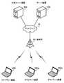
- the information processing system includes a server device 100, client devices 200, 200a, and 200b, and an external server device 300.
- the server device 100 and the external server device 300 are connected via the network 10.
- the client devices 200, 200a, and 200b are connected to the network 10 via the base station 20.
- the server apparatus 100 is a server computer that manages the client apparatuses 200, 200a, and 200b.
- the server device 100 protects the client devices 200, 200a, and 200b when the client devices 200, 200a, and 200b are lost or stolen.
- the server device 100 manages the locations of the client devices 200, 200a, and 200b.
- the server apparatus 100 instructs the client apparatuses 200, 200a, and 200b to lock the operation input, and instructs the client apparatuses 200, 200a, and 200b to delete predetermined data. This prevents data leakage when the client devices 200, 200a, 200b are lost or stolen.
- the client devices 200, 200a, and 200b are information processing devices that are easy to carry.
- the client devices 200, 200a, and 200b are laptop computers.
- the client devices 200, 200a, and 200b may be tablet computers or mobile phones.
- the client devices 200, 200a, and 200b perform wireless communication with the base station 20.
- the external server device 300 is a server computer that manages user schedule information.
- the external server device 300 manages boarding reservations for the user's aircraft. For example, the user can operate the client device 200 to make an aircraft boarding reservation in the external server device 300.
- the external server device 300 stores and manages the user ID (IDentifier), departure time, arrival time, and the like of the reserved user for the reserved flight. Furthermore, the external server device 300 manages the boarding procedure of the aircraft by the user and the issuing of a boarding pass accompanying the boarding procedure.
- IDentifier user IDentifier
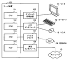
- FIG. 3 is a diagram illustrating a hardware example of the server device.
- the server apparatus 100 includes a CPU (Central Processing Unit) 101, a ROM (Read Only Memory) 102, a RAM (Random Access Memory) 103, a HDD (Hard Disk Drive) 104, a graphic processing device 105, an input interface 106, a disk drive 107, and the like.
- a communication interface 108 is included.
- the CPU 101 executes an OS (Operating System) program or an application program to control the entire server device 100.
- the ROM 102 stores a predetermined program such as a BIOS (Basic Input / Output System) program executed when the server apparatus 100 is activated.
- BIOS Basic Input / Output System
- the ROM 102 may be a rewritable nonvolatile memory.
- the RAM 103 temporarily stores at least part of an OS program and application programs executed by the CPU 101.
- the RAM 103 temporarily stores at least a part of data used for the processing of the CPU 101.
- the HDD 104 stores an OS program and application programs.
- the HDD 104 stores data used for the processing of the CPU 101.
- other types of non-volatile storage devices such as SSD (Solid State Drive) may be used.
- the graphic processing device 105 is connected to the monitor 11.
- the graphic processing device 105 displays an image on the monitor 11 in accordance with a command from the CPU 101.
- the input interface 106 is connected to input devices such as the keyboard 12 and the mouse 13.
- the input interface 106 outputs an input signal sent from the input device to the CPU 101.
- the disk drive 107 is a reading device that reads data stored in the recording medium 14.
- a program to be executed by the server apparatus 100 is recorded on the recording medium 14.
- the server device 100 can implement the functions described below by executing a program recorded in the recording medium 14. That is, the program can be recorded on a computer-readable recording medium 14 and distributed.
- a magnetic recording device for example, a magnetic recording device, an optical disk, a magneto-optical recording medium, or a semiconductor memory can be used.
- the magnetic recording device include an HDD, a flexible disk (FD), and a magnetic tape.
- Optical discs include CD (Compact Disc), CD-R (Recordable) / RW (ReWritable), DVD (Digital Versatile Disc), DVD-R / RW / RAM, and the like.
- Magneto-optical recording media include MO (Magneto-Optical disk).
- Semiconductor memories include flash memories such as USB (Universal (Serial Bus) memories.
- the communication interface 108 is connected to the network 10.
- the communication interface 108 can perform data communication with the external server device 300 via the network 10.
- the communication interface 108 can perform data communication with the client apparatuses 200, 200a, and 200b via the network 10 and the base station 20.
- the external server device 300 can also be realized by the same hardware configuration as the server device 100.
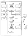
- FIG. 4 is a diagram illustrating a hardware example of the client device.
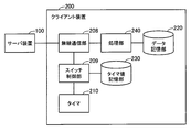
- the client device 200 includes a CPU 201, ROM 202, RAM 203, HDD 204, graphic processing device 205, display 205a, input interface 206, keyboard 206a, touch pad 206b, disk drive 207, wireless communication unit 208, antenna 208a, switch control unit 209, and switch. 209a and timer 210.
- the CPU 201, the ROM 202, the RAM 203, and the HDD 204 correspond to the CPU 101, the ROM 102, the RAM 103, and the HDD 104 described in FIG.
- the graphic processing device 205 is connected to the display 205a.
- the graphic processing device 205 displays an image on the display 205a in accordance with a command from the CPU 201.
- the input interface 206 is connected to input devices such as a keyboard 206a and a touch pad 206b.
- the input interface 206 outputs an input signal sent from the input device to the CPU 201.
- the disk drive 207 is a reading device that reads data stored in the recording medium 21.
- a program to be executed by the client device 200 is recorded on the recording medium 21.
- the client device 200 can implement the functions described below by executing a program recorded in the recording medium 21. That is, the program can be recorded and distributed on a computer-readable recording medium 21.
- a specific example of the recording medium 21 is the same as the recording medium 14 described with reference to FIG.
- the wireless communication unit 208 performs wireless signal processing. Specifically, the wireless communication unit 208 demodulates and decodes a signal received from the base station 20 via the antenna 208a, and outputs the obtained reception data to the CPU 201. In addition, the wireless communication unit 208 encodes and modulates transmission data acquired from the CPU 201, and transmits the obtained transmission signal to the base station 20 via the antenna 208a.
- the wireless communication unit 208 and the base station 20 can perform wireless communication using, for example, a PHS (Personal Handy-phone System) system.
- the wireless communication unit 208 transmits information on the currently communicating base station 20 to the server apparatus 100.
- the server apparatus 100 can manage the position of the client apparatus 200 based on the information.
- the switch control unit 209 accepts user operation details for the switch 209a.
- the switch 209a is a switching unit that accepts an on / off operation by the user.
- the switch control unit 209 changes on / off of the wireless communication unit 208 according to the operation content. Specifically, the switch control unit 209 stops the wireless communication unit 208 when the switch 209a is turned off. As a result, the wireless communication function of the client device 200 is turned off.
- the switch control unit 209 activates the wireless communication unit 208 when the switch 209a is turned on. As a result, the wireless communication function of the client device 200 is turned on.
- the switch control unit 209 turns on the wireless communication unit 208 based on the time measured by the timer 210.
- the timer 210 measures the time until the wireless communication unit 208 is turned on after the wireless communication unit 208 is turned off.
- the client devices 200a and 200b can also be realized by the same hardware configuration as that of the client device 200. Hereinafter, the description will be given focusing on the client device 200, but the same applies to the client devices 200a and 200b.
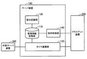
- FIG. 5 is a block diagram showing functions of the server device.
- the server device 100 includes a management information storage unit 110, a timer linkage unit 120, an instruction recording unit 130, and an instruction control unit 140.
- the functions of these units are realized on the server device 100 by the CPU 101 executing a predetermined program. However, all or part of the functions of these units may be implemented with dedicated hardware.
- the management information storage unit 110 stores management information.
- the management information includes a setting table.
- the setting table is data in which timer values for determining the timing for switching the wireless communication function from off to on in the client devices 200, 200a, and 200b are set.
- a data processing instruction to be executed by the client devices 200, 200a, and 200b when the wireless communication function is turned on is set. This instruction instructs a process for ensuring the security of the client devices 200, 200a, and 200b.
- the data stored in the client devices 200, 200a, and 200b may be erased, or the operation input to the client devices 200, 200a, and 200b may not be accepted (operation input lock).
- the timer cooperation unit 120 calculates a timer value for measuring the timing for turning on the wireless communication function based on the schedule information received from the external server device 300. Alternatively, the timer cooperation unit 120 acquires the timer value input by the user to the client device 200 from the client device 200. The timer cooperation unit 120 sets the timer value in the setting table stored in the management information storage unit 110. If there are a plurality of users, the timer cooperation unit 120 sets a timer value for each user. When there are a plurality of client devices, the timer cooperation unit 120 sets a timer value for each client device.
- the instruction recording unit 130 receives a data processing instruction and sets it in the setting table stored in the management information storage unit 110. For example, when the client device 200 is lost, the user operates another client device and inputs a data processing instruction to the instruction recording unit 130. The user may set the instruction by directly operating the server device 100. Further, an administrator who receives a notification from the user may set the instruction to the server device 100.
- the instruction control unit 140 When the instruction control unit 140 obtains an instruction content confirmation request from the client device 200, the instruction control unit 140 refers to the setting table stored in the management information storage unit 110 and confirms whether there is a data processing instruction. The instruction control unit 140 notifies the client device 200 of the confirmation result. If any instruction is set, the instruction control unit 140 instructs the client device 200 to perform data processing according to the instruction.
- FIG. 6 is a block diagram showing functions of the client device.
- the client device 200 includes a data storage unit 220, a timer value storage unit 230, and a processing unit 240 in addition to the units described in FIG.
- the function of the processing unit 240 is realized on the client device 200 by the CPU 201 executing a predetermined program. However, the function of the processing unit 240 may be implemented by dedicated hardware.
- the data storage unit 220 stores a data file handled by the client device 200. Sensitive information may be included in the data file.
- the timer value storage unit 230 stores a timer value. The timer value is notified from the server device 100. Specifically, the switch control unit 209 receives a timer value from the server device 100 via the wireless communication unit 208 and stores it in the timer value storage unit 230.
- the processing unit 240 confirms whether or not a data processing instruction is registered in the server device 100 via the wireless communication unit 208.
- the processing unit 240 performs processing on the data file stored in the data storage unit 220 in accordance with the data processing instruction registered in the server device 100. For example, when the data processing instruction is to delete predetermined data, the processing unit 240 deletes a data file designated in advance (or designated by the instruction). For example, when the data processing instruction is an instruction to lock the client device 200, the processing unit 240 locks the client device 200 so that a user operation input is not accepted.
- FIG. 7 shows an example of the data structure of the setting table.
- the setting table 111 is stored in the management information storage unit 110.
- the setting table 111 includes items of client device ID, user ID, automatic / manual classification, timer value, and instruction classification. Information arranged in the horizontal direction of each item is associated with each other to indicate information of one client device.
- the IDs of the client devices 200, 200a, and 200b are set.
- the user ID item an ID of a user who uses the client devices 200, 200a, and 200b is set.
- the item of automatic / manual classification information indicating the classification of whether the timer value is automatically acquired or the timer value is manually set is set.
- the timer cooperation unit 120 automatically calculates the timer value in cooperation with the external server device 300.
- the timer cooperation unit 120 acquires the timer value specified by the user.
- a timer value (for example, hour, minute, second) is set in the timer value item.
- the contents of data processing performed for ensuring security are set in the item of the instruction category.
- items of lock and erase are provided as data processing contents.
- the lock item an instruction to lock the client device is set.
- the deletion item an instruction to delete predetermined data (or a predetermined storage area) on the client device is set.
- the erasure target is designated in advance for the processing unit 240.
- the lock target range can be set in the lock item.
- an application to be locked, data, a storage area, an operation content, and the like may be set.
- an erasure target can be specified in the erasure item.
- the file name of the data file to be deleted, the area (directory or device) name, and the deletion method for example, replace with zero, write a random number, delete the key to decrypt the encrypted file, etc. It may be set.
- the client device ID is “CL001”
- the user ID is “U001”
- the automatic / manual classification is “automatic”
- the timer value is “2:00: 00”
- Information that lock is “0” and erase is “0” is set.
- the client device ID “CL001” indicates the ID of the client device 200. This record indicates that the client device 200 is used by the user with the user ID “U001”.
- the timer cooperation unit 120 automatically acquires a timer value set in the client device 200. Further, it indicates that the acquired timer value is 2 hours.
- the wireless communication function is turned on by the timer on the client device 200, it indicates that neither processing of locking the client device 200 nor erasing of data is performed.
- the client device ID is “CL002”
- the user ID is “U002”
- the automatic / manual classification is “manual”
- the timer value is “10:00:00”
- the instruction classification is locked. Is set to “0” and erase is set to “1”.
- the client device ID “CL002” indicates the ID of the client device 200a. This record indicates that the client device 200a is used by the user with the user ID “U002”.
- the timer value directly received by the timer cooperation unit 120 is set in the client device 200a. Further, it indicates that the acquired timer value is 1 hour.
- the wireless communication function is turned on by the timer on the client device 200a, it indicates that the client device 200a is not locked and that predetermined data is erased.
- the client device ID is “CL003”
- the user ID is “U003”
- the automatic / manual classification is “manual”
- the timer value is “1:30:00”
- the instruction classification is locked. Is set to "1" and erasure is set to "1".
- the client device ID “CL003” indicates the ID of the client device 200b. This record indicates that the client device 200b is used by the user with the user ID “U003”.
- the timer value directly received by the timer cooperation unit 120 is set in the client device 200b. Furthermore, it indicates that the acquired timer value is 1 hour 30 minutes. Then, when the wireless communication function is turned on by the timer on the client device 200b, both the lock of the client device 200b and the erasure of predetermined data are performed.
- each item in the instruction category is set to “0”.
- the user (or administrator) of each client device inputs instruction contents to the server device 100 when the client device is lost. Then, the instruction recording unit 130 updates the instruction classification corresponding to the processing content designated by the user to “1”.
- FIG. 8 is a diagram illustrating an example of a communication format of cooperation data.
- the cooperation data 400 is generated by the external server device 300 and transmitted to the server device 100.
- the cooperation data 400 includes schedule information registered in the external server device 300.
- the cooperation data 400 includes a transmission destination address field, a transmission source address field, a data length field, a data area field, and a check code field.
- the transmission destination address field the transmission destination address of the cooperation data 400 is set.
- the IP (Internet Protocol) address of the server apparatus 100 is used.
- the transmission source address field the transmission source address of the cooperation data 400 is set.
- the IP address of the external server device 300 is set.
- the data length field the data length of the data area field is set.
- the main body of the schedule information to be transmitted by the cooperation data 400 is set.
- the data area includes a user ID field, an aircraft flight number field, a departure date / time field, and an arrival date / time field.
- the user ID field the user ID of the user corresponding to the schedule information is set.
- the flight number of the aircraft is set in the aircraft flight number field.
- the departure date / time field the departure date / time of the aircraft is set.
- the arrival date and time of the aircraft is set in the arrival date and time field.
- the check code field a check code for detecting a data error on the receiving side is set.
- Each screen shown below can be used, for example, by selecting a link of each screen from a predetermined portal screen provided by the server device 100.
- the user or administrator can make desired settings from the following screens.
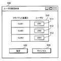
- FIG. 9 is a diagram showing an example of a user ID setting screen.
- the user ID setting screen 500 is generated by the timer cooperation unit 120 and displayed on the monitor 11.
- the user ID setting screen 500 includes a user ID input unit 510, a setting button 520, and a cancel button 530.
- the user ID input unit 510 is a form for inputting a user ID of a user who uses the client devices 200, 200a, and 200b.
- the user ID input unit 510 is provided with text boxes 511, 512, and 513 in association with the client device IDs of the client devices 200, 200a, and 200b.
- the text box 511 is a form for inputting a user ID corresponding to the client device 200 (client device ID “CL001”).
- a text box 512 is a form for inputting a user ID corresponding to the client device 200a (client device ID “CL002”).
- a text box 513 is a form for inputting a user ID corresponding to the client device 200b (client device ID “CL003”).
- the setting button 520 is a button for confirming the user ID input to the user ID input unit 510.
- the timer cooperation unit 120 acquires the setting contents of the text boxes 511, 512, and 513 and sets them in the setting table 111 stored in the management information storage unit 110.
- the cancel button 530 is a button for ending the user ID setting screen 500 without reflecting the setting contents of the user ID setting screen 500 in the setting table 111.
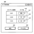
- FIG. 10 is a diagram illustrating an example of a timer setting screen.
- the timer setting screen 600 is generated by the timer cooperation unit 120 and displayed on the monitor 11.
- the timer setting screen 600 includes a timer value input unit 610, a setting button 620, and a cancel button 630.
- the timer value input unit 610 is a form for inputting the timer values of the client devices 200, 200a, and 200b.
- the timer value input unit 610 is provided with text boxes 611, 612, and 613 in association with the client device IDs of the client devices 200, 200a, and 200b.
- the text box 611 is a form for inputting the timer value of the client device 200.
- “automatic” is input. This means that the automatic / manual classification item setting “automatic” described in the setting table 111 of FIG. 7 is selected. That is, for the client device 200, the timer value is automatically acquired according to the schedule information.
- the text box 612 is a form for inputting the timer value of the client device 200a.
- “60” minutes is input. This is a setting when the timer value of the client device 200a is specified as 60 minutes.
- the text box 613 is a form for inputting the timer value of the client device 200b.
- “90” minutes is input. This is a setting when the timer value of the client device 200b is specified as 90 minutes.
- the setting button 620 is a button for confirming the timer value input to the timer value input unit 610.
- the timer cooperation unit 120 sets the setting table 111 as follows.
- the timer cooperation unit 120 sets the item of automatic / manual classification for the client device 200 to “automatic”.
- the timer cooperation unit 120 sets the automatic / manual classification item to “manual” and the timer value item to “1: 00: 00: 00” (60 minutes) for the client device 200a.
- the timer cooperation unit 120 sets the automatic / manual classification item to “manual” and the timer value item to “1:30:00” (90 minutes) for the client device 200b.
- the settings on the user ID setting screen 500 and the timer setting screen 600 are performed in advance by a user or an administrator when the client devices 200, 200a, and 200b are assigned to each user, for example. It can be changed later.
- the timer cooperation unit 120 transmits the updated timer value to the target client device, and prompts the timer value to be updated.
- the portal screen, the user ID setting screen 500, and the timer setting screen 600 described above can be displayed not only on the monitor 11 but also on a display included in each client device.
- the server device 100 has a Web server function and is accessible from each client device.
- a Web browser executed on the client device 200 accesses each of the screens and displays each screen on the display 205 a on the client device 200.
- the portal screen it is also possible to access a screen (instruction setting screen) for setting the item of the instruction category (processing when lost) shown in the setting table 111.
- a screen instruction setting screen
- the user or the administrator can issue an instruction to erase data or lock the device from the instruction setting screen from a client device different from the lost one.
- FIG. 11 is a flowchart illustrating timer value transmission processing according to the second embodiment.
- the external server device 300 transmits the cooperation data 400 to the server device 100 when detecting the start of the user's schedule (here, the user has performed the boarding procedure for the aircraft).
- the timer cooperation unit 120 receives the cooperation data 400 from the external server device 300.
- the cooperation data 400 includes schedule information for boarding the aircraft of the user (user ID “U001”) of the client device 200.
- the timer cooperation unit 120 refers to the setting table 111 stored in the management information storage unit 110, and identifies a client device corresponding to the user ID included in the cooperation data 400.
- the timer cooperation unit 120 refers to the setting table 111 and determines whether or not the setting of the automatic / manual classification item of the client device is “automatic”. If it is automatic, that is, if the timer value is automatically acquired, the process proceeds to step S13. If it is manual, the process ends. For example, since the automatic / manual classification of the client device 200 (client device ID “CL001”) corresponding to the user ID “U001” is “automatic”, the process proceeds to step S13.
- the timer cooperation unit 120 calculates a timer value based on the schedule information included in the cooperation data 400. Specifically, the time difference between the departure date and time and the arrival date and time of the cooperation data 400 is used as a timer value. For example, if the departure date is 13:00:00 and the arrival date is 15:00:00, the time difference (timer value) is 2 hours. A timer value may be obtained by adding a preliminary time to the time difference.
- Step S14 The timer cooperation unit 120 updates the setting of the timer value item in the setting table 111 with the obtained timer value in association with the client device ID.
- Step S15 The timer cooperation unit 120 transmits the timer value of the client device set in the setting table 111 to the client device specified in Step S12.
- the server device 100 calculates and transmits a timer value to the client device used by the corresponding user.
- the timer value is preferably calculated by adding the preliminary time. This is because the arrival date and time indicated by the schedule information is a schedule and may vary. For this reason, it is possible to reduce the possibility that the timing at which the wireless communication function is turned on will be before the actual arrival date and time by adding the preliminary time.
- the time may be acquired as a timer value.
- the arrival date and time (or the time obtained by adding preliminary time to the arrival date and time) may be used as the timer value.
- the switch control unit 209 receives the timer value transmitted from the server device 100 via the wireless communication unit 208, the switch control unit 209 updates the timer value stored in the timer value storage unit 230. Thereby, an appropriate timer value according to the user's schedule is set in the client device 200.
- FIG. 12 is a flowchart showing wireless communication control by a timer. In the following, the process illustrated in FIG. 12 will be described in order of step number. [Step S21]
- the switch control unit 209 detects that the switch 209a is turned off.
- the switch control unit 209 turns off the wireless communication unit 208.
- the switch control unit 209 starts measuring time by the timer 210.
- Step S24 Based on the count of the timer 210, the switch control unit 209 determines whether the time has elapsed by the timer value stored in the timer value storage unit 230. If it has elapsed, the process proceeds to step S25. If not, the process of step S24 is repeated until it has elapsed.
- the switch control unit 209 turns on the wireless communication unit 208.
- the wireless communication unit 208 starts transmission of radio waves for communication.
- the processing unit 240 inquires of the server device 100 for an instruction via the wireless communication unit 208.
- Step S28 The processing unit 240 receives the result of the inquiry from the server device 100, and determines whether there is an instruction. If there is an instruction, the process proceeds to step S31. If there is no instruction, the process proceeds to step S29.
- Step S29 The wireless communication unit 208 notifies the server apparatus 100 of information of the base station 20 that is currently communicating.
- the switch control unit 209 determines whether or not the switch 209a is turned on. If it is turned on, the process ends. If not, the process proceeds to step S22.
- the processing unit 240 receives an instruction registered in the server device 100 from the server device 100 via the wireless communication unit 208.
- the processing unit 240 executes processing according to the instruction. For example, when receiving an instruction to delete a predetermined data file, the processing unit 240 deletes the data file stored in the data storage unit 220. For example, when receiving an instruction to lock the client device 200, the processing unit 240 restricts operation input to the client device 200.
- the server apparatus 100 can also include the deletion target, the deletion method, the lock range, and the like in the instruction.
- Step S32 The processing unit 240 transmits the execution result of the process of step S31 to the server apparatus 100 via the wireless communication unit 208. At this time, the wireless communication unit 208 notifies the server apparatus 100 of information on the base station 20 that is currently communicating.
- the client device 200 measures the time by the timer value notified from the server device 100. When the time elapses, the client device 200 turns on the wireless communication function and inquires of the server device 100 whether the data processing instruction is registered.
- the client apparatus 200 regardless of whether or not an instruction is registered in the server apparatus 100, the client apparatus 200 notifies the server apparatus 100 of information on the currently communicating base station 20.
- the server device 100 can manage the current position of the client device 200 based on the information of the base station 20.
- step S30 you may transfer to step S30 after step S32. That is, if the switch 209a is not turned on, the wireless communication function may be turned off again. Further, the client device 200 may receive the time when the wireless communication function is turned on from the server device 100 as a timer value. In that case, in step S24, the switch control unit 209 determines whether the time has been reached using the timer 210. Then, the switch control unit 209 turns on the wireless communication unit 208 at the timing when the time is reached.
- FIG. 13 is a sequence diagram showing a series of processes. In the following, the process illustrated in FIG. 13 will be described in order of step number.
- the external server device 300 accepts an aircraft boarding procedure by the user of the client device 200.
- the external server device 300 generates the cooperation data 400 based on the information of the aircraft on which the user is boarded, and transmits it to the server device 100.
- the server device 100 receives the cooperation data 400 from the external server device 300.
- the server apparatus 100 refers to the setting table 111 stored in the management information storage unit 110 and identifies the client apparatus 200 corresponding to the user ID included in the cooperation data 400. According to the setting table 111, the automatic / manual classification for the client device 200 is “automatic”. For this reason, the server apparatus 100 calculates the timer value T based on the schedule information included in the cooperation data 400. When the server device 100 newly calculates the timer value T, the server device 100 registers the timer value T in the setting table 111 in association with the client device 200.
- Step ST14 The server apparatus 100 transmits the calculated timer value T to the client apparatus 200.
- the client device 200 receives the timer value T from the server device 100.
- Step ST15 The client device 200 stores the received timer value T in the timer value storage unit 230. That is, the client device 200 updates its own timer value setting to the timer value T received from the current timer value.
- Step ST16 The user turns off the switch 209a when boarding the aircraft.
- the client device 200 detects that the switch 209a is turned off. Then, the client device 200 turns off the wireless communication function. The client device 200 starts the count of the timer 210.
- Step ST17 Upon detecting that the time of the timer value T has elapsed by the timer 210, the client device 200 turns on the wireless communication function. Thereby, communication between the client apparatus 200 and the base station 20 is established.
- the client apparatus 200 inquires of the server apparatus 100 whether a data processing instruction is registered. In response to the inquiry, the server apparatus 100 refers to the setting table 111 and confirms whether an instruction is registered for the client apparatus 200.
- the server apparatus 100 responds to the client apparatus 200 that no instruction is registered.
- the client device 200 receives the response.
- the client apparatus 200 transmits information on the base station 20 that is currently communicating to the server apparatus 100.
- Step ST21 The client device 200 detects that the switch 209a is off. Then, the client device 200 turns off the wireless communication function. The client device 200 starts the count of the timer 210. After that, when the time has elapsed by the timer value T, the client device 200 performs the processes after step ST17 again.
- the timing for turning on the wireless communication function of the client device 200 from the server device 100 can be set.
- the external server device 300 transmits the cooperation data 400 to the server device 100 when the user's schedule is acquired. For this reason, it is possible to reduce the burden of the user performing settings by operating the client device 200 individually.
- the server device 100 sets a timer value in the client device 200 in accordance with the start of the schedule on the user side (boarding the aircraft). For this reason, it is possible to reduce the user's forgetting to set the timer value. Since it is possible to save the trouble of operating and setting the client device 200, it is particularly effective when there is only a short time before boarding or when rushing.
- step ST21 when the switch 209a is off, the wireless communication function is turned off again, so that generation of useless radio waves can be suppressed.
- step ST18 the client apparatus 200 inquires the server apparatus 100 about a data processing instruction. However, step ST18 may be omitted. In that case, after confirming that communication with the client apparatus 200 has been established in step ST17, the server apparatus 100 may spontaneously confirm the presence / absence of instruction registration and perform the process of step ST19.
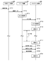
- FIG. 14 is a diagram illustrating a time chart of wireless communication control.
- the process illustrated in FIG. 14 will be described in order of step number. Note that the state of the user and each unit is as follows immediately before step ST31. It is assumed that the user is not on board the aircraft (being dismounted). The switch 209a is turned on. It is assumed that the timer 210 is in a count-off state (not counting). The wireless communication unit 208 is turned on.
- Step ST31 The user gets on the aircraft and turns off the switch 209a of the client device 200.
- the switch control unit 209 detects that the switch 209a has been changed to off.
- the wireless communication unit 208 is turned off by the switch control unit 209. As a result, the wireless communication function of the client device 200 is turned off.
- Step ST32 The timer 210 starts counting by the switch control unit 209. That is, the timer 210 is in a count-on state.
- Step ST33 The user gets off the aircraft (being alighting down).
- Step ST34 The timer 210 counts over the timer value stored in the timer value storage unit 230.
- the timer 210 stops counting.
- the switch control unit 209 detects the count over of the timer 210. Then, the switch control unit 209 turns on the switch state managed by itself. At this time, the switch 209a remains off.
- the wireless communication unit 208 is turned on by the switch control unit 209. As a result, the wireless communication function of the client device 200 is turned on.
- the client device 200 can stop the generation of radio waves during the period when the user is on the aircraft.
- the wireless communication function of the client device 200 is turned on, and a data processing instruction is sent from the server device 100 to the client device 200. Yes.
- the security function of the client device 200 can be exhibited and the security can be improved while suppressing the influence of the radio waves on the surroundings.
- the server device 100 and the client devices 200, 200a, and 200b can be used when using other transportation facilities such as trains and buses or when staying in a hospital.
- the user can set a schedule (boarding date, examination date, start time, end time, etc.) to stay in these transportation facilities and hospitals as schedule information in the external server device 300.
- the external server device 300 detects that the user has passed the train ticket gate or received a medical examination ticket at the hospital, the external server device 300 generates the linkage data 400 in the same manner, and sends the schedule information to the server device 100. Send.
- the server device 100 may have the function of the external server device 300. That is, the server apparatus 100 may manage user schedule information. In that case, the server apparatus 100 accepts the user's boarding procedure, and uses it as a trigger to transmit a timer value to the client apparatus 200.
- the server apparatus 100 calculates the timer value based on the schedule information
- the present invention is not limited to this.
- the server device 100 may transmit schedule information received from the external server device 300 to the client device 200. Then, the client device 200 may calculate a timer value based on the schedule information and store it in the timer value storage unit 230.
- the server apparatus 100 when the server apparatus 100 receives the cooperation data 400 from the external server apparatus 300, the timer value is calculated and transmitted to the client apparatuses 200, 200a, and 200b.
- the server apparatus 100 may receive the cooperation data 400 from the external server apparatus 300 in advance and manage each user's schedule.
- processing of the server apparatus 100 in this case will be described.
- the same structure shall be shown by the same name and code
- the external server apparatus 300 transmits the cooperation data 400 to the server apparatus 100 when accepting a schedule reservation (for example, an aircraft boarding reservation) in which each user stays at a predetermined place.
- a schedule reservation for example, an aircraft boarding reservation
- the management information storage unit 110 stores a schedule management table for managing the schedule of each user.
- the timer cooperation unit 120 updates the schedule management table based on the cooperation data 400 and manages the schedule of each user.
- FIG. 15 is a diagram showing an example of the data structure of the schedule management table.
- the schedule management table 112 includes items for user ID, start date and time, and end date and time. Information arranged in the horizontal direction of each item is associated with each other to indicate one user's information.
- a user ID is set in the user ID item.
- the start date / time item the start date / time of the schedule is set.
- the end date and time the end date and time of the schedule is set.
- the schedule management table 112 includes information that the user ID is “U001”, the start date and time is “2011/4/1 13:00:00”, and the end date and time is “2011/4/1 15:00:00”. Is set.
- the timer cooperation unit 120 can also register a plurality of records for one user and manage a plurality of schedules. Next, a processing procedure of the server apparatus 100 having the above configuration will be described.
- FIG. 16 is a flowchart illustrating timer value transmission processing according to the third embodiment. In the following, the process illustrated in FIG. 16 will be described in order of step number.
- the external server device 300 transmits the cooperation data 400 to the server device 100 when the user makes a schedule reservation (here, an aircraft boarding reservation).
- the timer cooperation unit 120 receives the cooperation data 400 from the external server device 300.
- the cooperation data 400 includes schedule information for boarding the aircraft of the user (user ID “U001”) of the client device 200.
- the timer cooperation unit 120 refers to the setting table 111 stored in the management information storage unit 110, and identifies the client device corresponding to the user ID included in the cooperation data 400.
- the timer cooperation unit 120 refers to the setting table 111 and determines whether or not the setting of the automatic / manual classification item of the client device is “automatic”. If it is automatic, that is, if the timer value is automatically acquired, the process proceeds to step S43. If it is manual, the process ends. For example, the client apparatus 200 (client apparatus ID “CL001”) corresponding to the user ID “U001” has the automatic / manual classification “automatic”, and thus the process proceeds to step S43.
- the timer cooperation unit 120 updates the schedule management table 112 stored in the management information storage unit 110 based on the schedule information. For example, the timer cooperation unit 120 registers the schedule of the user with the user ID “U001” in the schedule management table 112.
- Step S44 The timer cooperation unit 120 monitors the start time of the schedule.
- Step S45 The timer cooperation unit 120 determines whether or not the start date and time of the schedule is close. If it is close to the start date time, the process proceeds to step S46. If it is not close to the start date time, the process proceeds to step S44.
- being close to the start date and time can be set in advance, for example, 30 minutes before the start date and time. Such settings may be set in advance for each user in the schedule management table 112.
- the timer cooperation unit 120 calculates a timer value based on the schedule management table 112. Specifically, the time difference between the start date and time and the end date and time of the schedule is used as the timer value. For example, if the start date and time is 13:00:00 and the end date and time is 15:00:00 for the user ID “U001”, the time difference (timer value) is 2 hours. A timer value may be obtained by adding a preliminary time to the time difference.
- the timer cooperation unit 120 updates the setting of the timer value item in the setting table 111 with the obtained timer value in association with the client device ID.
- the timer cooperation unit 120 transmits the timer value of the client device set in the setting table 111 to the client device specified in Step S42.
- the server device 100 manages the schedule of each user, and calculates and transmits a timer value to the client device used by the corresponding user when the start time of the schedule approaches.
- the timer cooperation unit 120 may calculate a timer value in advance when receiving the schedule information.
- the timer value it is preferable to calculate the timer value by adding the preliminary time. This is because the end date and time indicated by the schedule information is a schedule and may vary. For this reason, it is possible to reduce the possibility that the timing at which the wireless communication function is turned on will be before the actual end date and time by adding the preliminary time.
- the time may be acquired as a timer value.
- the end date and time (or the time obtained by adding the preliminary time to the end date and time) may be used as the timer value.
- the switch control unit 209 receives the timer value transmitted from the server device 100 via the wireless communication unit 208, the switch control unit 209 updates the timer value stored in the timer value storage unit 230. Thereby, an appropriate timer value according to the user's schedule is set in the client device 200.
- the server device 100 can also manage the schedule of each user, and the same effects as those of the second embodiment can be obtained.
- the boarding reservation for the aircraft is exemplified, but the present invention can also be applied when staying in a place where the influence of radio waves should be considered, such as other transportation facilities or hospitals.
- the third embodiment is particularly effective when staying in a place such as a hospital where an entrance procedure is not performed in advance.
- the client devices 200, 200a, and 200b perform wireless communication control using a timer.
- wireless communication control can be performed also by the number of times of password input such as BIOS and OS. Therefore, in the fourth embodiment, control based on the number of times the password is input is exemplified.
- the same name / symbol as the name / symbol used in the second embodiment is used to indicate the same configuration.
- the processing procedure of the client apparatus 200 will be described. However, the same applies to the client devices 200a and 200b.
- FIG. 17 is a flowchart illustrating wireless communication control according to the fourth embodiment. In the following, the process illustrated in FIG. 17 will be described in order of step number. [Step S51]
- the switch control unit 209 detects that the switch 209a is turned off.
- Step S52 The switch control unit 209 turns off the wireless communication unit 208.
- the processing unit 240 detects a BIOS password input failure.
- Step S54 The processing unit 240 determines whether or not the number of input failures exceeds a threshold value. If exceeded, the process proceeds to step S55. If not, the process proceeds to Step S53.
- the threshold value is stored in advance in a storage unit accessible by the processing unit 240.
- the switch control unit 209 turns on the wireless communication unit 2008.
- the wireless communication unit 208 starts transmission of radio waves for communication.
- the processing unit 240 inquires of the server device 100 for an instruction via the wireless communication unit 208.
- Step S58 The processing unit 240 receives the result of the inquiry from the server device 100, and determines whether there is an instruction. If there is an instruction, the process proceeds to step S61. If there is no instruction, the process proceeds to step S59.
- Step S ⁇ b> 59 The wireless communication unit 208 notifies the server apparatus 100 of information on the currently communicating base station 20.
- Step S60 The switch control unit 209 determines whether or not the switch 209a is turned on. If it is turned on, the process ends. If not, the process proceeds to step S52.
- the processing unit 240 receives an instruction registered in the server device 100 from the server device 100 via the wireless communication unit 208.
- the processing unit 240 executes processing according to the instruction.
- Step S62 The processing unit 240 transmits the execution result of the process of step S51 to the server device 100 via the wireless communication unit 208. At this time, the wireless communication unit 208 notifies the server apparatus 100 of information on the base station 20 that is currently communicating.
- the client device 200 when the wireless communication function is turned off, the client device 200 counts the number of failures of the BIOS login password. Then, when the number of failures exceeds a predetermined threshold, the client device 200 turns on the wireless communication function, makes an inquiry to the server device 100, and executes the security function.
- the client device 200 communicates with the server device 100 and confirms registration of the data processing instruction.
- the client device 200 may count the number of times that an OS password or a password input failure when using a predetermined application is used.
Landscapes
- Engineering & Computer Science (AREA)
- Human Computer Interaction (AREA)
- Computer Networks & Wireless Communication (AREA)
- Signal Processing (AREA)
- Mobile Radio Communication Systems (AREA)
- Computer And Data Communications (AREA)
- Telephonic Communication Services (AREA)
Abstract
無線通信機能をオンにするタイミングを容易に設定できる。 制御部(1b)は、情報処理装置(2)の無線通信機能をオンにするタイミングを決定するための制御情報(3)を生成する。通信部(1a)は、制御情報(3)を送信する。通信部(2a)は、通信部(1a)が送信した制御情報(3)を受信する。制御部(2b)は、情報処理装置(2)の無線通信機能がオフにされると、制御情報(3)に基づくタイミングで当該無線通信機能をオンにする。
Description
本件は情報処理システム、制御方法および制御プログラムに関する。
従来、小型・軽量で持ち運び容易な情報処理装置が利用されている。このような情報処理装置は、所在が不明になったり、盗難にあったりすることがある。そこで、情報処理装置が備える無線通信機能を用いて、当該情報処理装置を他の装置から遠隔管理する方法が提案されている。
例えば、情報処理装置から、その所在を示す位置情報を所定のセンターに定期的に送信して、当該装置の位置を管理する方法が提案されている。この方法では、情報処理装置は、電源がオフになると補助電源を用いてタイマを駆動する。タイマがタイムアップすると、補助電源から元の電源に切り替えて位置情報の送信を行う。
また、例えば、通信圏外にある情報処理装置で、個人情報へのアクセスが誤ったパスワードで複数回行われたり、操作が所定時間以上行われたりしたときに、当該装置の位置情報を基地局に送信する方法が提案されている。
更に、例えば、情報処理装置への操作が数分間ない場合に、当該装置をパスワード入力待ち状態に移行させ、パスワードの入力ミスが数回あると、所定の電話番号からの着信を受けない限り操作を制限する紛失中状態に移行させる方法が提案されている。この方法では、紛失した当該装置が通信可能圏内にあるとき、位置情報に加えて、当該装置に格納されたデータを圧縮し、サーバ装置に送信可能にすることも提案されている。
ところで、情報処理装置が無線通信のために発する電波は周囲の装置の動作に影響を及ぼす可能性がある。例えば、航空機内の計器や医療施設内の医療機器に対する電波の影響が懸念される。このため、このような場所では無線通信機能をオフにした状態で、情報処理装置が利用されることがある。
しかし、無線通信機能がオフのままであると情報処理装置の遠隔管理が困難になる。そこで、情報処理装置の無線通信機能を何れのタイミングでオンにするかをどのようにして情報処理装置に容易に設定可能とするかが問題となる。
本発明はこのような点に鑑みてなされたものであり、無線通信機能をオンにするタイミングを容易に設定できるようにした情報処理システム、制御方法および制御プログラムを提供することを目的とする。
上記目的を達成するために、第1の情報処理装置と第2の情報処理装置とを有する情報処理システムが提供される。第1の情報処理装置は、第1の制御部と第1の通信部とを備える。第1の制御部は、他の装置の無線通信機能をオンにするタイミングを決定するための制御情報を生成する。第1の通信部は、第1の制御部が生成した制御情報を送信する。第2の情報処理装置は、第2の通信部と第2の制御部とを備える。第2の通信部は、第1の通信部が送信した制御情報を受信する。第2の制御部は、自装置の無線通信機能がオフにされると、制御情報に基づき、当該タイミングで当該無線通信機能をオンにする。
また、上記目的を達成するために、第1の情報処理装置および第2の情報処理装置を有する情報処理システムが実行する制御方法が提供される。この制御方法では、第1の情報処理装置が、第2の情報処理装置の無線通信機能をオンにするタイミングを決定するための制御情報を生成し、生成した制御情報を送信する。第2の情報処理装置が、第1の情報処理装置が送信した制御情報を受信し、自装置の無線通信機能がオフにされると、制御情報に基づき、当該タイミングで当該無線通信機能をオンにする。
また、上記目的を達成するために、制御プログラムが提供される。この制御プログラムは、コンピュータに、情報処理装置の無線通信機能がオフにされたときに情報処理装置が当該無線通信機能をオンにするタイミングを決定するための制御情報を生成し、生成した制御情報を情報処理装置に送信する処理を実行させる。
上記の情報処理システムおよび制御方法によれば、第2の情報処理装置の無線通信機能をオンにするタイミングを容易に設定できる。
また、上記の制御プログラムによれば、情報処理装置の無線通信機能をオンにするタイミングを容易に設定できる。
また、上記の制御プログラムによれば、情報処理装置の無線通信機能をオンにするタイミングを容易に設定できる。
本発明の上記および他の目的、特徴および利点は本発明の例として好ましい実施の形態を表す添付の図面と関連した以下の説明により明らかになるであろう。
以下、本実施の形態を図面を参照して説明する。
[第1の実施の形態]
図1は、第1の実施の形態の情報処理システムを示す図である。この情報処理システムは、情報処理装置1,2を有する。情報処理装置1,2は、無線で通信可能に接続されている。ただし、情報処理装置1は有線のネットワークに接続されており、当該ネットワークに接続された無線の基地局と情報処理装置2との間が無線で通信可能となっていてもよい。
[第1の実施の形態]
図1は、第1の実施の形態の情報処理システムを示す図である。この情報処理システムは、情報処理装置1,2を有する。情報処理装置1,2は、無線で通信可能に接続されている。ただし、情報処理装置1は有線のネットワークに接続されており、当該ネットワークに接続された無線の基地局と情報処理装置2との間が無線で通信可能となっていてもよい。
情報処理装置1は、通信部1aおよび制御部1bを有する。
通信部1aは、制御部1bが生成した制御情報3を送信する。
制御部1bは、制御情報3を生成する。制御情報3は、情報処理装置2の無線通信機能をオンにするタイミングT1を決定するための情報である。例えば、制御情報3は、情報処理装置2の無線通信機能をオフにした後、当該無線通信機能をオンにするまでの時間を示すものである。また、例えば、制御情報3は、情報処理装置2の無線通信機能をオンにする時刻(年月日日時分秒など)を示すものでもよい。また、例えば、制御情報3は、情報処理装置2に当該タイミングT1を算出させるための情報でもよい。
通信部1aは、制御部1bが生成した制御情報3を送信する。
制御部1bは、制御情報3を生成する。制御情報3は、情報処理装置2の無線通信機能をオンにするタイミングT1を決定するための情報である。例えば、制御情報3は、情報処理装置2の無線通信機能をオフにした後、当該無線通信機能をオンにするまでの時間を示すものである。また、例えば、制御情報3は、情報処理装置2の無線通信機能をオンにする時刻(年月日日時分秒など)を示すものでもよい。また、例えば、制御情報3は、情報処理装置2に当該タイミングT1を算出させるための情報でもよい。
情報処理装置2は、通信部2aおよび制御部2bを有する。
通信部2aは、通信部1aが送信した制御情報3を受信する。
制御部2bは、情報処理装置2の無線通信機能がオフにされると、制御情報3に基づき、制御情報3で決定されるタイミングT1で当該無線通信機能をオンにする。
通信部2aは、通信部1aが送信した制御情報3を受信する。
制御部2bは、情報処理装置2の無線通信機能がオフにされると、制御情報3に基づき、制御情報3で決定されるタイミングT1で当該無線通信機能をオンにする。
例えば、制御情報3が、無線通信機能をタイミングT0でオフにした後、当該無線通信機能をオンにするまでの時間を示すとする。その場合、制御部2bは、無線通信機能のオフ後、その時間が経過すると、無線通信機能をオンにする。
また、例えば、制御情報3が、無線通信機能をオンにする時刻を示すとする。その場合、制御部2bは、無線通信機能のオフ後、その時刻に達すると、無線通信機能をオンにする。
この情報処理システムによれば、制御部1bにより、情報処理装置2の無線通信機能をオンにするタイミングT1を決定するための制御情報3が生成される。通信部1aにより、制御情報3が送信される。通信部2aにより、通信部1aが送信した制御情報3が受信される。制御部2bは、情報処理装置2の無線通信機能がオフにされると、制御情報3に基づき、当該タイミングT1で当該無線通信機能がオンにされる。
これにより、情報処理装置2の無線通信機能をオンにするタイミングを容易に設定できる。具体的には、情報処理装置2は、情報処理装置1で生成された制御情報3に基づいてタイミングT1を決定するので、ユーザが情報処理装置2にタイミングT1を直接設定する負担を軽減できる。
ここで、情報処理装置2が無線通信のために発する電波は周囲の他の装置の動作に影響を及ぼす可能性がある。例えば、航空機内の計器や医療施設内の医療機器に対する電波の影響が懸念される。このため、情報処理装置2の無線通信機能をオンにするタイミングT1を変更したい場合として、このような交通機関や施設を利用する場合が考えられる。具体的には、航空機や医療施設内などでの滞在予定期間で無線通信機能をオフにし、その期間が経過すればオンに切り替えるといった設定をしたい場合である。上記情報処理システムによれば、このような場合に情報処理装置2の無線通信機能をオンにするタイミングを容易に設定でき、ユーザにとって利便性がよい。
また、情報処理装置1は、ユーザの交通機関や施設の利用予定などのスケジュール情報を管理してもよい。あるいは、情報処理装置1は、他の情報処理装置から当該スケジュール情報を取得してもよい。そして、情報処理装置1は、当該スケジュールに基づいて制御情報3を生成してもよい。このようにすれば、ユーザのスケジュール情報に連動してタイミングT1を決定でき、より適切なタイミングT1の情報処理装置2への設定を一層容易に行える。
[第2の実施の形態]
図2は、第2の実施の形態の情報処理システムを示す図である。この情報処理システムは、サーバ装置100、クライアント装置200,200a,200bおよび外部サーバ装置300を含む。サーバ装置100と外部サーバ装置300は、ネットワーク10を介して接続されている。クライアント装置200,200a,200bは、基地局20を介してネットワーク10に接続されている。
図2は、第2の実施の形態の情報処理システムを示す図である。この情報処理システムは、サーバ装置100、クライアント装置200,200a,200bおよび外部サーバ装置300を含む。サーバ装置100と外部サーバ装置300は、ネットワーク10を介して接続されている。クライアント装置200,200a,200bは、基地局20を介してネットワーク10に接続されている。
サーバ装置100は、クライアント装置200,200a,200bを管理するサーバコンピュータである。サーバ装置100は、クライアント装置200,200a,200bが紛失されたり、盗難に遭ったりしたときに、クライアント装置200,200a,200bを保護する。具体的には、サーバ装置100は、クライアント装置200,200a,200bの所在を管理する。また、サーバ装置100は、操作入力をロックするようにクライアント装置200,200a,200bに指示したり、所定のデータを消去するようにクライアント装置200,200a,200bに指示したりする。これにより、クライアント装置200,200a,200bが紛失されたり、盗難に遭ったりしたときの、データの漏えい防止を図っている。
クライアント装置200,200a,200bは、携帯容易な情報処理装置である。例えば、クライアント装置200,200a,200bは、ラップトップ型コンピュータである。クライアント装置200,200a,200bは、タブレット型コンピュータや携帯電話機などでもよい。クライアント装置200,200a,200bは、基地局20と無線通信を行う。
外部サーバ装置300は、ユーザのスケジュール情報を管理するサーバコンピュータである。外部サーバ装置300は、ユーザの航空機の搭乗予約を管理する。例えば、ユーザはクライアント装置200を操作して、外部サーバ装置300に航空機の搭乗予約を行える。外部サーバ装置300は、予約された便につき、予約したユーザのユーザID(IDentifier)、出発時刻および到着時刻などを記憶・管理する。更に、外部サーバ装置300は、ユーザによる航空機の搭乗手続や、搭乗手続に伴う搭乗券の発券を管理する。
図3は、サーバ装置のハードウェア例を示す図である。サーバ装置100は、CPU(Central Processing Unit)101、ROM(Read Only Memory)102、RAM(Random Access Memory)103、HDD(Hard Disk Drive)104、グラフィック処理装置105、入力インタフェース106、ディスクドライブ107および通信インタフェース108を有する。
CPU101は、OS(Operating System)プログラムやアプリケーションプログラムを実行して、サーバ装置100全体を制御する。
ROM102は、サーバ装置100の起動時に実行されるBIOS(Basic Input / Output System)プログラムなどの所定のプログラムを記憶する。ROM102は、書き換え可能な不揮発性メモリであってもよい。
ROM102は、サーバ装置100の起動時に実行されるBIOS(Basic Input / Output System)プログラムなどの所定のプログラムを記憶する。ROM102は、書き換え可能な不揮発性メモリであってもよい。
RAM103は、CPU101が実行するOSプログラムやアプリケーションプログラムの少なくとも一部を一時的に記憶する。また、RAM103は、CPU101の処理に用いられるデータの少なくとも一部を一時的に記憶する。
HDD104は、OSプログラムやアプリケーションプログラムを記憶する。また、HDD104は、CPU101の処理に用いられるデータを記憶する。なお、HDD104に代えて(または、HDD104と併せて)、SSD(Solid State Drive)など他の種類の不揮発性の記憶装置を用いてもよい。
グラフィック処理装置105は、モニタ11に接続される。グラフィック処理装置105は、CPU101からの命令に従って、画像をモニタ11に表示させる。
入力インタフェース106は、キーボード12やマウス13などの入力デバイスに接続される。入力インタフェース106は、入力デバイスから送られる入力信号をCPU101に出力する。
入力インタフェース106は、キーボード12やマウス13などの入力デバイスに接続される。入力インタフェース106は、入力デバイスから送られる入力信号をCPU101に出力する。
ディスクドライブ107は、記録媒体14に格納されたデータを読み取る読取装置である。記録媒体14には、例えば、サーバ装置100に実行させるプログラムが記録されている。サーバ装置100は、例えば、記録媒体14に記録されたプログラムを実行することで、後述するような機能を実現できる。すなわち、当該プログラムはコンピュータ読み取り可能な記録媒体14に記録して配布可能である。
記録媒体14としては、例えば、磁気記録装置、光ディスク、光磁気記録媒体、半導体メモリを使用できる。磁気記録装置には、HDD、フレキシブルディスク(FD)、磁気テープなどがある。光ディスクには、CD(Compact Disc)、CD-R(Recordable)/RW(ReWritable)、DVD(Digital Versatile Disc)、DVD-R/RW/RAMなどがある。光磁気記録媒体には、MO(Magneto-Optical disk)などがある。半導体メモリには、USB(Universal Serial Bus)メモリなどのフラッシュメモリがある。
通信インタフェース108は、ネットワーク10に接続される。通信インタフェース108は、ネットワーク10を介して外部サーバ装置300とデータ通信を行える。通信インタフェース108は、ネットワーク10および基地局20を介してクライアント装置200,200a,200bとデータ通信を行える。
なお、外部サーバ装置300もサーバ装置100と同様のハードウェア構成により実現できる。
図4は、クライアント装置のハードウェア例を示す図である。クライアント装置200は、CPU201、ROM202、RAM203、HDD204、グラフィック処理装置205、ディスプレイ205a、入力インタフェース206、キーボード206a、タッチパッド206b、ディスクドライブ207、無線通信部208、アンテナ208a、スイッチ制御部209、スイッチ209aおよびタイマ210を有する。
図4は、クライアント装置のハードウェア例を示す図である。クライアント装置200は、CPU201、ROM202、RAM203、HDD204、グラフィック処理装置205、ディスプレイ205a、入力インタフェース206、キーボード206a、タッチパッド206b、ディスクドライブ207、無線通信部208、アンテナ208a、スイッチ制御部209、スイッチ209aおよびタイマ210を有する。
ここで、CPU201、ROM202、RAM203およびHDD204は、図3で説明したCPU101、ROM102、RAM103およびHDD104に対応するため、説明を省略する。
グラフィック処理装置205は、ディスプレイ205aに接続される。グラフィック処理装置205は、CPU201からの命令に従って、画像をディスプレイ205aに表示させる。
入力インタフェース206は、キーボード206aやタッチパッド206bなどの入力デバイスに接続される。入力インタフェース206は、入力デバイスから送られる入力信号をCPU201に出力する。
ディスクドライブ207は、記録媒体21に格納されたデータを読み取る読取装置である。記録媒体21には、例えば、クライアント装置200に実行させるプログラムが記録されている。クライアント装置200は、例えば、記録媒体21に記録されたプログラムを実行することで、後述するような機能を実現できる。すなわち、当該プログラムはコンピュータ読み取り可能な記録媒体21に記録して配布可能である。記録媒体21の具体例は、図3で説明した記録媒体14と同様である。
無線通信部208は、無線信号処理を行う。具体的には、無線通信部208は、基地局20からアンテナ208aを介して受信した信号を復調・復号し、得られた受信データをCPU201に出力する。また、無線通信部208は、CPU201から取得した送信データを符号化・変調し、得られた送信信号をアンテナ208aを介して基地局20へ送信する。無線通信部208および基地局20は、例えば、PHS(Personal Handy-phone System)方式での無線通信が可能である。また、無線通信部208は、現在通信中の基地局20の情報をサーバ装置100に送信する。サーバ装置100は、当該情報によりクライアント装置200の位置を管理できる。
スイッチ制御部209は、スイッチ209aに対するユーザの操作内容を受け付ける。スイッチ209aは、ユーザによるオン/オフ操作を受け付ける切替部である。スイッチ制御部209は、当該操作内容に応じて、無線通信部208のオン/オフを変更する。具体的には、スイッチ制御部209は、スイッチ209aがオフにされると、無線通信部208を停止させる。これにより、クライアント装置200の無線通信機能がオフになる。一方、スイッチ制御部209は、スイッチ209aがオンにされると、無線通信部208を起動させる。これにより、クライアント装置200の無線通信機能がオンになる。
また、スイッチ制御部209は、タイマ210で計測した時間に基づいて、無線通信部208をオンにする。
タイマ210は、無線通信部208がオフになった後、無線通信部208をオンにするまでの時間を計測する。
タイマ210は、無線通信部208がオフになった後、無線通信部208をオンにするまでの時間を計測する。
なお、クライアント装置200a,200bもクライアント装置200と同様のハードウェア構成により実現できる。以下、クライアント装置200に着目して説明するが、クライアント装置200a,200bに関しても同様である。
図5は、サーバ装置の機能を示すブロック図である。サーバ装置100は、管理情報記憶部110、タイマ連携部120、指示記録部130および指示制御部140を有する。これらのユニットの機能は、CPU101が所定のプログラムを実行することにより、サーバ装置100上に実現される。ただし、これらのユニットの機能の全部または一部を専用のハードウェアで実装してもよい。
管理情報記憶部110は、管理情報を記憶する。管理情報には、設定テーブルが含まれる。設定テーブルは、クライアント装置200,200a,200bで無線通信機能をオフからオンに切り替えるタイミングを決定するためのタイマ値を設定したデータである。また、設定テーブルには、無線通信機能がオンになったときにクライアント装置200,200a,200bに実行させるデータ処理の指示が設定される。当該指示は、クライアント装置200,200a,200bのセキュリティを確保するための処理を指示するものである。例えば、クライアント装置200,200a,200bに格納されたデータを消去する、クライアント装置200,200a,200bに対する操作入力を受け付けないようにする(操作入力のロック)などが考えられる。
タイマ連携部120は、外部サーバ装置300から受け付けたスケジュール情報に基づいて、無線通信機能をオンにするタイミングを計るためのタイマ値を計算する。あるいは、タイマ連携部120は、ユーザがクライアント装置200に入力したタイマ値をクライアント装置200から取得する。タイマ連携部120は、管理情報記憶部110に記憶された設定テーブルに当該タイマ値を設定する。タイマ連携部120は、複数のユーザが存在すれば、ユーザごとにタイマ値の設定を行う。タイマ連携部120は、複数のクライアント装置が存在すれば、クライアント装置ごとにタイマ値の設定を行う。
指示記録部130は、データ処理の指示を受け付け、管理情報記憶部110に記憶された設定テーブルに設定する。ユーザは、例えば、クライアント装置200を紛失した際に、他のクライアント装置を操作して指示記録部130にデータ処理の指示を入力する。ユーザは、サーバ装置100を直接操作して当該指示を設定してもよい。また、ユーザからの連絡を受けた管理者が、サーバ装置100に当該指示を設定してもよい。
指示制御部140は、クライアント装置200から指示内容の確認要求を取得すると、管理情報記憶部110に記憶された設定テーブルを参照して、データ処理の指示の有無を確認する。指示制御部140は、その確認結果をクライアント装置200に通知する。指示制御部140は、何れかの指示が設定されていれば、当該指示に応じたデータ処理を行うようクライアント装置200に指示する。
図6は、クライアント装置の機能を示すブロック図である。クライアント装置200は、図4で説明したユニットに加えて、データ記憶部220、タイマ値記憶部230および処理部240を有する。処理部240の機能は、CPU201が所定のプログラムを実行することにより、クライアント装置200上に実現される。ただし、処理部240の機能を専用のハードウェアで実装してもよい。
データ記憶部220は、クライアント装置200で扱うデータファイルを記憶する。データファイルの中には、機密情報が含まれ得る。
タイマ値記憶部230は、タイマ値を記憶する。タイマ値は、サーバ装置100から通知される。具体的には、スイッチ制御部209は、無線通信部208を介してサーバ装置100からタイマ値を受信し、タイマ値記憶部230に格納する。
タイマ値記憶部230は、タイマ値を記憶する。タイマ値は、サーバ装置100から通知される。具体的には、スイッチ制御部209は、無線通信部208を介してサーバ装置100からタイマ値を受信し、タイマ値記憶部230に格納する。
処理部240は、スイッチ制御部209により、無線通信部208がオンにされると、サーバ装置100にデータ処理の指示が登録されているか否かを無線通信部208を介して確認する。処理部240は、サーバ装置100に登録されたデータ処理の指示に応じて、データ記憶部220に記憶されたデータファイルに対する処理などを行う。例えば、データ処理の指示が所定のデータの消去である場合、処理部240は予め指定された(あるいは、当該指示で指定される)データファイルを消去する。また、例えば、データ処理の指示が、クライアント装置200をロックする指示である場合、処理部240は、クライアント装置200をロックして、ユーザの操作入力を受け付けない状態にする。
図7は、設定テーブルのデータ構造例を示す図である。設定テーブル111は、管理情報記憶部110に格納される。設定テーブル111には、クライアント装置ID、ユーザID、自動/手動区分、タイマ値および指示区分の項目が設けられている。各項目の横方向に並べられた情報同士が互いに関連付けられて、1つのクライアント装置の情報を示す。
クライアント装置IDの項目には、クライアント装置200,200a,200bのIDが設定される。ユーザIDの項目には、クライアント装置200,200a,200bを利用するユーザのIDが設定される。自動/手動区分の項目には、タイマ値を自動的に取得するか、タイマ値を手動で設定するかの区分を示す情報が設定される。タイマ値を自動的に取得する場合、タイマ連携部120は外部サーバ装置300と連携して、タイマ値を自動的に計算する。タイマ値を手動で設定する場合、タイマ連携部120はユーザによって指定されたタイマ値を取得する。タイマ値の項目には、タイマ値(例えば、時分秒)が設定される。指示区分の項目には、セキュリティ確保のために行うデータ処理の内容が設定される。指示区分には、データ処理の内容として、ロックおよび消去の項目が設けられている。ロックの項目は、当該クライアント装置をロックする旨の指示が設定される。消去の項目には、当該クライアント装置上の所定のデータ(あるいは、所定の記憶領域)を消去する旨の指示が設定される。消去対象は、処理部240に対して事前に指定される。
ここで、ロックの項目では、ロックの対象範囲を設定することもできる。具体的には、ロック対象とするアプリケーション、データ、記憶領域および操作内容などを設定してもよい。また、消去の項目では、消去対象を指定することもできる。具体的には、消去するデータファイルのファイル名、領域(ディレクトリやデバイス)名および消去の方法(例えば、ゼロで置き換える、乱数を書き込む、暗号化ファイルを復号するための鍵を消去する)などを設定してもよい。
ここで、例えば、設定テーブル111には、クライアント装置IDが“CL001”、ユーザIDが“U001”、自動/手動区分が“自動”、タイマ値が“2:00:00”、指示区分につき、ロックが“0”、消去が“0”という情報が設定される。
クライアント装置ID“CL001”は、クライアント装置200のIDを示す。当該レコードは、クライアント装置200がユーザID“U001”のユーザにより利用されていることを示している。また、タイマ連携部120が、クライアント装置200に設定するタイマ値を自動的に取得することを示す。更に、取得されたタイマ値が2時間であることを示す。そして、クライアント装置200上でタイマにより無線通信機能がオンになったとき、クライアント装置200のロックおよびデータの消去の何れの処理も行わないことを示す。
また、例えば、設定テーブル111には、クライアント装置IDが“CL002”、ユーザIDが“U002”、自動/手動区分が“手動”、タイマ値が“1:00:00”、指示区分につき、ロックが“0”、消去が“1”という情報が設定される。
クライアント装置ID“CL002”は、クライアント装置200aのIDを示す。当該レコードは、クライアント装置200aがユーザID“U002”のユーザにより利用されていることを示している。また、タイマ連携部120が直接受け付けたタイマ値を、クライアント装置200aに設定することを示す。更に、取得されたタイマ値が1時間であることを示す。そして、クライアント装置200a上でタイマにより無線通信機能がオンになったとき、クライアント装置200aのロックは行わないこと、および、所定のデータの消去を行うこと、を示す。
また、例えば、設定テーブル111には、クライアント装置IDが“CL003”、ユーザIDが“U003”、自動/手動区分が“手動”、タイマ値が“1:30:00”、指示区分につき、ロックが“1”、消去が“1”という情報が設定される。
クライアント装置ID“CL003”は、クライアント装置200bのIDを示す。当該レコードは、クライアント装置200bがユーザID“U003”のユーザにより利用されていることを示している。また、タイマ連携部120が直接受け付けたタイマ値を、クライアント装置200bに設定することを示す。更に、取得されたタイマ値が1時間30分であることを示す。そして、クライアント装置200b上でタイマにより無線通信機能がオンになったとき、クライアント装置200bのロックおよび所定のデータの消去の両方の処理を行うことを示す。
なお、指示区分の各項目の初期状態は、全て“0”としておく。各クライアント装置のユーザ(または管理者)は、クライアント装置を紛失した際に、サーバ装置100に指示内容を入力する。すると、指示記録部130は、ユーザによって指定された処理内容に対応する指示区分を“1”に更新する。
また、タイマ値としては、カウントする時間を設定する他、時刻を設定してもよい。
図8は、連携データの通信フォーマット例を示す図である。連携データ400は、外部サーバ装置300により生成され、サーバ装置100に送信される。連携データ400は、外部サーバ装置300に登録されたスケジュール情報を含む。連携データ400は、送信先アドレスフィールド、送信元アドレスフィールド、データ長フィールド、データ領域フィールドおよびチェックコードフィールドを含む。
図8は、連携データの通信フォーマット例を示す図である。連携データ400は、外部サーバ装置300により生成され、サーバ装置100に送信される。連携データ400は、外部サーバ装置300に登録されたスケジュール情報を含む。連携データ400は、送信先アドレスフィールド、送信元アドレスフィールド、データ長フィールド、データ領域フィールドおよびチェックコードフィールドを含む。
送信先アドレスフィールドには、連携データ400の送信先のアドレスが設定される。例えば、サーバ装置100のIP(Internet Protocol)アドレスである。
送信元アドレスフィールドには、連携データ400の送信元のアドレスが設定される。例えば、外部サーバ装置300のIPアドレスである。
送信元アドレスフィールドには、連携データ400の送信元のアドレスが設定される。例えば、外部サーバ装置300のIPアドレスである。
データ長フィールドには、データ領域フィールドのデータ長が設定される。
データ領域フィールドには、連携データ400で送信するスケジュール情報の本体が設定される。データ領域は、ユーザIDフィールド、航空機便名フィールド、出発日時フィールドおよび到着日時フィールドを含む。
データ領域フィールドには、連携データ400で送信するスケジュール情報の本体が設定される。データ領域は、ユーザIDフィールド、航空機便名フィールド、出発日時フィールドおよび到着日時フィールドを含む。
ユーザIDフィールドは、当該スケジュール情報に対応するユーザのユーザIDが設定される。航空機便名フィールドには、航空機の便名が設定される。出発日時フィールドには、当該航空機の出発日時が設定される。到着日時フィールドには、当該航空機の到着日時が設定される。チェックコードフィールドには、受信側でデータの誤りを検出するためのチェックコードが設定される。
次に、クライアント装置200,200a,200bに関する設定を行うためにサーバ装置100が生成する画面例を説明する。以下に示す各画面は、例えば、サーバ装置100が提供する所定のポータル画面から各画面のリンクを選択することで利用可能である。ユーザや管理者は、以下に示す各画面から、所望の設定を行える。
図9は、ユーザID設定画面の例を示す図である。ユーザID設定画面500は、タイマ連携部120により生成され、モニタ11に表示される。ユーザID設定画面500には、ユーザID入力部510、設定ボタン520およびキャンセルボタン530が設けられている。
ユーザID入力部510は、クライアント装置200,200a,200bを利用するユーザのユーザIDを入力するためのフォームである。ユーザID入力部510には、クライアント装置200,200a,200bの各クライアント装置IDに対応付けて、テキストボックス511,512,513が設けられている。
テキストボックス511は、クライアント装置200(クライアント装置ID“CL001”)に対応するユーザIDを入力するためのフォームである。テキストボックス512は、クライアント装置200a(クライアント装置ID“CL002”)に対応するユーザIDを入力するためのフォームである。テキストボックス513は、クライアント装置200b(クライアント装置ID“CL003”)に対応するユーザIDを入力するためのフォームである。
設定ボタン520は、ユーザID入力部510に入力されたユーザIDを確定するためのボタンである。タイマ連携部120は、設定ボタン520が押下されると、テキストボックス511,512,513の設定内容を取得して、管理情報記憶部110に記憶された設定テーブル111に設定する。
キャンセルボタン530は、ユーザID設定画面500の設定内容を設定テーブル111に反映させずに、ユーザID設定画面500を終了させるボタンである。
図10は、タイマ設定画面の例を示す図である。タイマ設定画面600は、タイマ連携部120により生成され、モニタ11に表示される。タイマ設定画面600には、タイマ値入力部610、設定ボタン620およびキャンセルボタン630が設けられている。
図10は、タイマ設定画面の例を示す図である。タイマ設定画面600は、タイマ連携部120により生成され、モニタ11に表示される。タイマ設定画面600には、タイマ値入力部610、設定ボタン620およびキャンセルボタン630が設けられている。
タイマ値入力部610は、クライアント装置200,200a,200bのタイマ値を入力するためのフォームである。タイマ値入力部610には、クライアント装置200,200a,200bの各クライアント装置IDに対応付けて、テキストボックス611,612,613が設けられている。
テキストボックス611は、クライアント装置200のタイマ値を入力するためのフォームである。テキストボックス611には、“自動”と入力されている。これは、図7の設定テーブル111で説明した自動/手動区分の項目の設定“自動”を選択することを意味する。すなわち、クライアント装置200に関して、スケジュール情報に合わせてタイマ値を自動取得する場合の設定である。
テキストボックス612は、クライアント装置200aのタイマ値を入力するためのフォームである。テキストボックス612には、“60”(分)と入力されている。これは、クライアント装置200aのタイマ値を60分と指定する場合の設定である。
テキストボックス613は、クライアント装置200bのタイマ値を入力するためのフォームである。テキストボックス613には、“90”(分)と入力されている。これは、クライアント装置200bのタイマ値を90分と指定する場合の設定である。
設定ボタン620は、タイマ値入力部610に入力されたタイマ値を確定するためのボタンである。タイマ値入力部610で例示した入力内容で設定ボタン620が押下されると、タイマ連携部120は設定テーブル111に次のように設定する。タイマ連携部120は、クライアント装置200について、自動/手動区分の項目を“自動”とする。タイマ連携部120は、クライアント装置200aについて、自動/手動区分の項目を“手動”に、タイマ値の項目を“1:00:00”(60分)とする。タイマ連携部120は、クライアント装置200bについて、自動/手動区分の項目を“手動”に、タイマ値の項目を“1:30:00”(90分)とする。
ユーザID設定画面500およびタイマ設定画面600での設定は、例えば、クライアント装置200,200a,200bを各ユーザに割り当てるときに、ユーザや管理者により予め行われる。後で変更することも可能である。
タイマ設定画面600により、タイマ値の設定が更新されると、タイマ連携部120は、更新後のタイマ値を対象のクライアント装置に送信し、タイマ値の更新を促す。
なお、以上で示したポータル画面、ユーザID設定画面500およびタイマ設定画面600は、モニタ11に限らず、各クライアント装置が備えるディスプレイに表示させることができる。例えば、サーバ装置100はWebサーバ機能を備え、各クライアント装置からアクセス可能にする。例えば、クライアント装置200で実行されるWebブラウザは、上記各画面にアクセスし、クライアント装置200上のディスプレイ205aに各画面を表示させる。
なお、以上で示したポータル画面、ユーザID設定画面500およびタイマ設定画面600は、モニタ11に限らず、各クライアント装置が備えるディスプレイに表示させることができる。例えば、サーバ装置100はWebサーバ機能を備え、各クライアント装置からアクセス可能にする。例えば、クライアント装置200で実行されるWebブラウザは、上記各画面にアクセスし、クライアント装置200上のディスプレイ205aに各画面を表示させる。
更に、ポータル画面からは、設定テーブル111で示した指示区分の項目(紛失時の処理)の設定を行うための画面(指示設定画面)へアクセスすることもできる。ユーザや管理者は、クライアント装置を紛失した際には、紛失したものとは別のクライアント装置から、当該指示設定画面からデータの消去や装置のロックなどの指示を行える。
次に、以上の構成の情報処理システムの処理手順を説明する。クライアント装置200に関する処理を主に説明するが、クライアント装置200a,200bに関しても同様である。
図11は、第2の実施の形態のタイマ値送信処理を示すフローチャートである。以下、図11に示す処理をステップ番号に沿って説明する。
[ステップS11]外部サーバ装置300は、ユーザのスケジュール開始(ここでは、ユーザが航空機の搭乗手続を行ったこと)を検知したときに、連携データ400をサーバ装置100に送信する。タイマ連携部120は、外部サーバ装置300から連携データ400を受信する。例えば、連携データ400には、クライアント装置200のユーザ(ユーザID“U001”)の航空機搭乗のスケジュール情報が含まれる。
[ステップS11]外部サーバ装置300は、ユーザのスケジュール開始(ここでは、ユーザが航空機の搭乗手続を行ったこと)を検知したときに、連携データ400をサーバ装置100に送信する。タイマ連携部120は、外部サーバ装置300から連携データ400を受信する。例えば、連携データ400には、クライアント装置200のユーザ(ユーザID“U001”)の航空機搭乗のスケジュール情報が含まれる。
[ステップS12]タイマ連携部120は、管理情報記憶部110に記憶された設定テーブル111を参照して、連携データ400に含まれるユーザIDに対応するクライアント装置を特定する。タイマ連携部120は、設定テーブル111を参照して、当該クライアント装置の自動/手動区分の項目の設定が“自動”であるか否かを判定する。自動である、すなわち、タイマ値を自動取得する場合、処理をステップS13に進める。手動である場合、処理を終了する。例えば、ユーザID“U001”に対応するクライアント装置200(クライアント装置ID“CL001”)は、自動/手動区分が“自動”であるので、処理をステップS13に進める。
[ステップS13]タイマ連携部120は、連携データ400に含まれるスケジュール情報に基づいて、タイマ値を算出する。具体的には、連携データ400の出発日時と到着日時との時間差をタイマ値とする。例えば、出発日時が13時00分00秒、到着日時が15時00分00秒であれば、その時間差(タイマ値)は2時間である。なお、当該時間差に予備時間を加えてタイマ値としてもよい。
[ステップS14]タイマ連携部120は、クライアント装置IDに対応付けて設定テーブル111のタイマ値の項目の設定を、求めたタイマ値で更新する。
[ステップS15]タイマ連携部120は、ステップS12で特定したクライアント装置に、設定テーブル111に設定された当該クライアント装置のタイマ値を送信する。
[ステップS15]タイマ連携部120は、ステップS12で特定したクライアント装置に、設定テーブル111に設定された当該クライアント装置のタイマ値を送信する。
このようにして、サーバ装置100は、外部サーバ装置300から連携データ400を受信すると、対応するユーザが利用するクライアント装置に対してタイマ値を算出して送信する。
ここで、ステップS13で例示したように、タイマ値は予備時間を加算して算出することが好ましい。なぜなら、スケジュール情報で示される到着日時は予定であり、変動し得る。このため、予備時間を加算することで、無線通信機能がオンになるタイミングが実際の到着日時より前になってしまう可能性を低減できるからである。
また、ステップS13では、時刻をタイマ値として取得してもよい。その場合、到着日時(または到着日時に予備時間を加えた時刻)をタイマ値としてもよい。
スイッチ制御部209は、サーバ装置100が送信したタイマ値を、無線通信部208を介して受信すると、タイマ値記憶部230に格納されたタイマ値を更新する。これにより、ユーザのスケジュールに合わせた適切なタイマ値がクライアント装置200に設定される。
スイッチ制御部209は、サーバ装置100が送信したタイマ値を、無線通信部208を介して受信すると、タイマ値記憶部230に格納されたタイマ値を更新する。これにより、ユーザのスケジュールに合わせた適切なタイマ値がクライアント装置200に設定される。
図12は、タイマによる無線通信制御を示すフローチャートである。以下、図12に示す処理をステップ番号に沿って説明する。
[ステップS21]スイッチ制御部209は、スイッチ209aがオフにされたことを検知する。
[ステップS21]スイッチ制御部209は、スイッチ209aがオフにされたことを検知する。
[ステップS22]スイッチ制御部209は、無線通信部208をオフにする。
[ステップS23]スイッチ制御部209は、タイマ210による時間の計測をスタートする。
[ステップS23]スイッチ制御部209は、タイマ210による時間の計測をスタートする。
[ステップS24]スイッチ制御部209は、タイマ210のカウントに基づいて、タイマ値記憶部230に記憶されたタイマ値の分だけ、時間が経過したかを判定する。経過した場合、処理をステップS25に進める。経過していない場合、経過するまで本ステップS24の処理を繰り返す。
[ステップS25]スイッチ制御部209は、無線通信部208をオンにする。
[ステップS26]無線通信部208は、通信用の電波の発信を開始する。
[ステップS27]処理部240は、無線通信部208を介して、サーバ装置100に指示を問い合わせる。
[ステップS26]無線通信部208は、通信用の電波の発信を開始する。
[ステップS27]処理部240は、無線通信部208を介して、サーバ装置100に指示を問い合わせる。
[ステップS28]処理部240は、問い合わせの結果をサーバ装置100から受信し、指示の有無を判定する。指示があった場合、処理をステップS31に進める。指示がない場合、処理をステップS29に進める。
[ステップS29]無線通信部208は、現在通信している基地局20の情報をサーバ装置100に通知する。
[ステップS30]スイッチ制御部209は、スイッチ209aがオンにされているか否かを判定する。オンにされている場合、処理を終了する。オンでない場合、処理をステップS22に進める。
[ステップS30]スイッチ制御部209は、スイッチ209aがオンにされているか否かを判定する。オンにされている場合、処理を終了する。オンでない場合、処理をステップS22に進める。
[ステップS31]処理部240は、無線通信部208を介して、サーバ装置100に登録された指示をサーバ装置100から受ける。処理部240は、当該指示に応じた処理を実行する。例えば、所定のデータファイルを消去する旨の指示を受けた場合、処理部240はデータ記憶部220に格納された当該データファイルを消去する。また、例えば、クライアント装置200をロックする旨の指示を受けた場合、処理部240はクライアント装置200に対する操作入力を制限する。サーバ装置100は、消去対象、消去方法およびロック範囲などを当該指示に含めることもできる。
[ステップS32]処理部240は、無線通信部208を介して、ステップS31の処理の実行結果をサーバ装置100に送信する。このとき、無線通信部208は、現在通信している基地局20の情報をサーバ装置100に通知する。
このように、クライアント装置200は、無線通信機能がオフになると、サーバ装置100から通知されたタイマ値の分だけ時間を計測する。クライアント装置200は、当該時間が経過すると、無線通信機能をオンにして、データ処理の指示が登録されているかをサーバ装置100に問い合わせる。
ここで、サーバ装置100に指示が登録されているか否かに関わらず、クライアント装置200は、現在通信している基地局20の情報をサーバ装置100に通知する。例えば、サーバ装置100は、基地局20の情報に基づいて、クライアント装置200の現在の位置を管理できる。
なお、ステップS32の後に、ステップS30に遷移してもよい。すなわち、スイッチ209aがオンになっていなければ、無線通信機能を再度オフにしてもよい。
更に、クライアント装置200は、タイマ値として、無線通信機能をオンにする時刻をサーバ装置100から受信してもよい。その場合、ステップS24において、スイッチ制御部209は、タイマ210を用いて当該時刻に達したか判断する。そして、スイッチ制御部209は、当該時刻に達したタイミングで無線通信部208をオンにする。
更に、クライアント装置200は、タイマ値として、無線通信機能をオンにする時刻をサーバ装置100から受信してもよい。その場合、ステップS24において、スイッチ制御部209は、タイマ210を用いて当該時刻に達したか判断する。そして、スイッチ制御部209は、当該時刻に達したタイミングで無線通信部208をオンにする。
また、クライアント装置200は、上記ステップS29を省略して、ステップS30を実行してもよいし、ステップS32で基地局情報の通知を省略してもよい。
図13は、一連の処理を示すシーケンス図である。以下、図13に示す処理をステップ番号に沿って説明する。
図13は、一連の処理を示すシーケンス図である。以下、図13に示す処理をステップ番号に沿って説明する。
[ステップST11]外部サーバ装置300は、クライアント装置200のユーザによる航空機の搭乗手続を受け付ける。
[ステップST12]外部サーバ装置300は、ユーザが搭乗する航空機の情報に基づいて、連携データ400を生成して、サーバ装置100に送信する。サーバ装置100は、外部サーバ装置300から連携データ400を受信する。
[ステップST12]外部サーバ装置300は、ユーザが搭乗する航空機の情報に基づいて、連携データ400を生成して、サーバ装置100に送信する。サーバ装置100は、外部サーバ装置300から連携データ400を受信する。
[ステップST13]サーバ装置100は、管理情報記憶部110に記憶された設定テーブル111を参照して、連携データ400に含まれるユーザIDに対応するクライアント装置200を特定する。設定テーブル111によれば、クライアント装置200につき自動/手動区分が“自動”である。このため、サーバ装置100は、連携データ400に含まれるスケジュール情報に基づいてタイマ値Tを算出する。サーバ装置100は、タイマ値Tを新たに算出した場合、当該タイマ値Tをクライアント装置200に対応付けて設定テーブル111に登録する。
[ステップST14]サーバ装置100は、算出したタイマ値Tをクライアント装置200に送信する。クライアント装置200は、サーバ装置100からタイマ値Tを受信する。
[ステップST15]クライアント装置200は、受信したタイマ値Tをタイマ値記憶部230に格納する。すなわち、クライアント装置200は、自身のタイマ値の設定を、現在のタイマ値から受信したタイマ値Tに更新する。
[ステップST16]ユーザは、航空機へ搭乗するとき、スイッチ209aをオフにする。クライアント装置200は、スイッチ209aがオフにされたことを検知する。すると、クライアント装置200は、無線通信機能をオフにする。クライアント装置200は、タイマ210のカウントをスタートさせる。
[ステップST17]クライアント装置200は、タイマ210によりタイマ値Tの時間が経過したことを検知すると、無線通信機能をオンにする。これにより、クライアント装置200と基地局20との間の通信が確立される。
[ステップST18]クライアント装置200は、サーバ装置100にデータ処理の指示が登録されているかを問い合わせる。サーバ装置100は、当該問い合わせに応じて、設定テーブル111を参照し、クライアント装置200につき指示が登録されているかを確認する。
[ステップST19]サーバ装置100は、何れの指示も登録されていない旨をクライアント装置200に応答する。クライアント装置200は、当該応答を受信する。
[ステップST20]クライアント装置200は、現在通信している基地局20の情報をサーバ装置100に送信する。
[ステップST20]クライアント装置200は、現在通信している基地局20の情報をサーバ装置100に送信する。
[ステップST21]クライアント装置200は、スイッチ209aがオフであることを検知する。すると、クライアント装置200は、無線通信機能をオフにする。クライアント装置200は、タイマ210のカウントをスタートさせる。その後、タイマ値Tの分だけ時間が経過すると、クライアント装置200はステップST17以降の処理を再度行う。
このようにして、サーバ装置100からクライアント装置200の無線通信機能をオンにするタイミングを設定できる。特に、外部サーバ装置300は、ユーザのスケジュールを取得したときに、サーバ装置100に連携データ400を送信する。このため、ユーザがクライアント装置200を個別に操作して設定を行う負担を軽減できる。
また、ユーザ側のスケジュールの開始(航空機への搭乗)に応じて、サーバ装置100は、クライアント装置200にタイマ値を設定する。このため、ユーザのタイマ値の設定のし忘れを低減できる。クライアント装置200を操作して設定する手間を省けるので、搭乗までに短時間しかない場合や急いでいる場合に、特に効果的である。
また、ステップST21において、スイッチ209aがオフである場合に、無線通信機能を再度オフにするようにしたので、無駄な電波の発生を抑制できる。
ここで、ステップST18では、クライアント装置200から、サーバ装置100にデータ処理の指示を問い合わせるものとしたが、このステップST18を省いてもよい。その場合、サーバ装置100は、ステップST17でクライアント装置200との通信が確立されたことを確認した後に、指示の登録有無を自発的に確認して、ステップST19の処理を行えばよい。
ここで、ステップST18では、クライアント装置200から、サーバ装置100にデータ処理の指示を問い合わせるものとしたが、このステップST18を省いてもよい。その場合、サーバ装置100は、ステップST17でクライアント装置200との通信が確立されたことを確認した後に、指示の登録有無を自発的に確認して、ステップST19の処理を行えばよい。
次に、航空機に搭乗する際のユーザおよびクライアント装置200の各部の状態を具体的に説明する。
図14は、無線通信制御のタイムチャートを示す図である。以下、図14に示す処理をステップ番号に沿って説明する。なお、ステップST31の直前では、ユーザおよび各部の状態は次の通りとする。ユーザは航空機に搭乗していない(降機中)とする。スイッチ209aはオンとする。タイマ210はカウントオフ(カウントしていない状態)であるとする。無線通信部208はオンとする。
図14は、無線通信制御のタイムチャートを示す図である。以下、図14に示す処理をステップ番号に沿って説明する。なお、ステップST31の直前では、ユーザおよび各部の状態は次の通りとする。ユーザは航空機に搭乗していない(降機中)とする。スイッチ209aはオンとする。タイマ210はカウントオフ(カウントしていない状態)であるとする。無線通信部208はオンとする。
[ステップST31]ユーザは、航空機に搭乗し、クライアント装置200のスイッチ209aをオフにする。スイッチ制御部209は、スイッチ209aがオフに変更されたことを検知する。無線通信部208は、スイッチ制御部209によりオフに変更される。これにより、クライアント装置200の無線通信機能がオフになる。
[ステップST32]タイマ210は、スイッチ制御部209によりカウントスタートする。すなわち、タイマ210は、カウントオンの状態となる。
[ステップST33]ユーザは、航空機から降りる(降機中となる)。
[ステップST33]ユーザは、航空機から降りる(降機中となる)。
[ステップST34]タイマ210は、タイマ値記憶部230に記憶されたタイマ値をカウントオーバーする。タイマ210は、カウントをストップする。
[ステップST35]スイッチ制御部209は、タイマ210のカウントオーバーを検知する。すると、スイッチ制御部209は、自身で管理するスイッチ状態をオンとする。このとき、スイッチ209aはオフの状態のままである。無線通信部208は、スイッチ制御部209によりオンに変更される。これにより、クライアント装置200の無線通信機能がオンになる。
[ステップST35]スイッチ制御部209は、タイマ210のカウントオーバーを検知する。すると、スイッチ制御部209は、自身で管理するスイッチ状態をオンとする。このとき、スイッチ209aはオフの状態のままである。無線通信部208は、スイッチ制御部209によりオンに変更される。これにより、クライアント装置200の無線通信機能がオンになる。
このように、クライアント装置200は、ユーザが航空機に搭乗する期間中、電波の発生を停止できる。加えて、航空機に搭乗する期間が終了したときに、スイッチ209aのオン/オフの状態に関わらず、クライアント装置200の無線通信機能をオンにし、サーバ装置100からクライアント装置200へデータ処理の指示を行える。これによって、電波による周囲への影響を抑制しながら、クライアント装置200のセキュリティ機能を発揮させ、セキュリティ性を向上させることができる。
なお、上記説明ではユーザが航空機に搭乗する場合を例示したが、これに限らない。例えば、電車やバスなどの他の交通機関を利用する場合や病院に滞在する場合にも、サーバ装置100やクライアント装置200,200a,200bを利用可能である。その場合、ユーザは、これらの交通機関や病院に滞在する予定(搭乗日、診察日、開始時刻、終了時刻など)を、スケジュール情報として外部サーバ装置300に設定できる。外部サーバ装置300は、ユーザが電車の改札を通過したことや、病院で診察券を受領したことなどを検知したときに、連携データ400を同様に生成して、当該スケジュール情報をサーバ装置100に送信する。
また、サーバ装置100が外部サーバ装置300の機能を備えてもよい。すなわち、サーバ装置100は、ユーザのスケジュール情報を管理してもよい。その場合、サーバ装置100がユーザの搭乗手続を受け付け、それを契機として、クライアント装置200にタイマ値を送信する。
更に、サーバ装置100がスケジュール情報に基づいてタイマ値を算出するものとしたが、これに限らない。例えば、サーバ装置100は、外部サーバ装置300から受信したスケジュール情報をクライアント装置200に送信してもよい。そして、クライアント装置200が当該スケジュール情報に基づいて、タイマ値を算出し、タイマ値記憶部230に格納してもよい。
[第3の実施の形態]
次に、第3の実施の形態を説明する。前述の第2の実施の形態との相違点を主に説明し、同様の事項は説明を省略する。
次に、第3の実施の形態を説明する。前述の第2の実施の形態との相違点を主に説明し、同様の事項は説明を省略する。
第2の実施の形態では、サーバ装置100が外部サーバ装置300から連携データ400を受信したときに、タイマ値を算出してクライアント装置200,200a,200bに送信する旨を例示した。
これに対し、サーバ装置100は、外部サーバ装置300から連携データ400を事前に受信しておき、各ユーザのスケジュールを管理してもよい。第3の実施の形態では、この場合のサーバ装置100の処理を説明する。
ここで、第3の実施の形態では、第2の実施の形態で用いた名称・符号と同一の名称・符号により、同一の構成を示すものとする。
ただし、外部サーバ装置300は、各ユーザが所定の場所に滞在するスケジュール予約(例えば、航空機の搭乗予約)を受け付けたときに、連携データ400をサーバ装置100に送信する。
ただし、外部サーバ装置300は、各ユーザが所定の場所に滞在するスケジュール予約(例えば、航空機の搭乗予約)を受け付けたときに、連携データ400をサーバ装置100に送信する。
また、管理情報記憶部110は、各ユーザのスケジュールを管理するためのスケジュール管理テーブルを記憶する。タイマ連携部120は、連携データ400に基づいて当該スケジュール管理テーブルを更新し、各ユーザのスケジュールを管理する。
図15は、スケジュール管理テーブルのデータ構造例を示す図である。スケジュール管理テーブル112には、ユーザID、開始日時および終了日時の項目が設けられている。各項目の横方向に並べられた情報同士が互いに関連付けられて、1ユーザの情報を示す。
ユーザIDの項目には、ユーザIDが設定される。開始日時の項目には、スケジュールの開始日時が設定される。終了日時には、スケジュールの終了日時が設定される。
例えば、スケジュール管理テーブル112には、ユーザIDが“U001”、開始日時が“2011/4/1 13:00:00”、終了日時が“2011/4/1 15:00:00”という情報が設定される。
例えば、スケジュール管理テーブル112には、ユーザIDが“U001”、開始日時が“2011/4/1 13:00:00”、終了日時が“2011/4/1 15:00:00”という情報が設定される。
これは、ユーザID“U001”で示されるユーザが所定の場所(例えば、航空機)での滞在を介する予定の日時が2011年4月1日13時00分00秒であり、当該滞在が終了する予定の日時が2011年4月1日15時00分00秒であることを示す。
タイマ連携部120は、1ユーザに対して複数のレコードを登録し、複数のスケジュールを管理することもできる。
次に、以上の構成のサーバ装置100の処理手順を説明する。
次に、以上の構成のサーバ装置100の処理手順を説明する。
図16は、第3の実施の形態のタイマ値送信処理を示すフローチャートである。以下、図16に示す処理をステップ番号に沿って説明する。
[ステップS41]外部サーバ装置300は、ユーザがスケジュールの予約(ここでは、航空機の搭乗予約)を行ったときに、連携データ400をサーバ装置100に送信する。タイマ連携部120は、外部サーバ装置300から連携データ400を受信する。例えば、連携データ400には、クライアント装置200のユーザ(ユーザID“U001”)の航空機搭乗のスケジュール情報が含まれる。
[ステップS41]外部サーバ装置300は、ユーザがスケジュールの予約(ここでは、航空機の搭乗予約)を行ったときに、連携データ400をサーバ装置100に送信する。タイマ連携部120は、外部サーバ装置300から連携データ400を受信する。例えば、連携データ400には、クライアント装置200のユーザ(ユーザID“U001”)の航空機搭乗のスケジュール情報が含まれる。
[ステップS42]タイマ連携部120は、管理情報記憶部110に記憶された設定テーブル111を参照して、連携データ400に含まれるユーザIDに対応するクライアント装置を特定する。タイマ連携部120は、設定テーブル111を参照して、当該クライアント装置の自動/手動区分の項目の設定が“自動”であるか否かを判定する。自動である、すなわち、タイマ値を自動取得する場合、処理をステップS43に進める。手動である場合、処理を終了する。例えば、ユーザID“U001”に対応するクライアント装置200(クライアント装置ID“CL001”)は、自動/手動区分が“自動”であるので、処理をステップS43に進める。
[ステップS43]タイマ連携部120は、スケジュール情報に基づいて、管理情報記憶部110に記憶されたスケジュール管理テーブル112を更新する。例えば、タイマ連携部120は、ユーザID“U001”のユーザのスケジュールを、スケジュール管理テーブル112に登録する。
[ステップS44]タイマ連携部120は、当該スケジュールの開始時間を監視する。
[ステップS45]タイマ連携部120は、当該スケジュールの開始日時が間近であるか否かを判定する。開始日時間近である場合、処理をステップS46に進める。開始日時間近でない場合、処理をステップS44に進める。ここで、開始日時間近であるとは、例えば、開始日時の30分前というように、予め設定が可能である。このような設定を、スケジュール管理テーブル112に対して、ユーザごとに事前に設定可能としてもよい。
[ステップS45]タイマ連携部120は、当該スケジュールの開始日時が間近であるか否かを判定する。開始日時間近である場合、処理をステップS46に進める。開始日時間近でない場合、処理をステップS44に進める。ここで、開始日時間近であるとは、例えば、開始日時の30分前というように、予め設定が可能である。このような設定を、スケジュール管理テーブル112に対して、ユーザごとに事前に設定可能としてもよい。
[ステップS46]タイマ連携部120は、スケジュール管理テーブル112に基づいて、タイマ値を算出する。具体的には、スケジュールの開始日時と終了日時との時間差をタイマ値とする。例えば、ユーザID“U001”に対し、開始日時が13時00分00秒、終了日時が15時00分00秒であれば、その時間差(タイマ値)は2時間である。なお、当該時間差に予備時間を加えてタイマ値としてもよい。
[ステップS47]タイマ連携部120は、クライアント装置IDに対応付けて設定テーブル111のタイマ値の項目の設定を、求めたタイマ値で更新する。
[ステップS48]タイマ連携部120は、ステップS42で特定したクライアント装置に、設定テーブル111に設定された当該クライアント装置のタイマ値を送信する。
[ステップS48]タイマ連携部120は、ステップS42で特定したクライアント装置に、設定テーブル111に設定された当該クライアント装置のタイマ値を送信する。
このようにして、サーバ装置100は、各ユーザのスケジュールを管理し、スケジュールの開始時間が迫ると、対応するユーザが利用するクライアント装置に対してタイマ値を算出して送信する。なお、タイマ連携部120は、スケジュール情報を受信したときに、タイマ値を予め算出しておいてもよい。
ここで、タイマ値は予備時間を加算して算出することが好ましい。なぜなら、スケジュール情報で示される終了日時は予定であり、変動し得る。このため、予備時間を加算することで、無線通信機能がオンになるタイミングが実際の終了日時より前になってしまう可能性を低減できるからである。
また、ステップS46では、時刻をタイマ値として取得してもよい。その場合、終了日時(または終了日時に予備時間を加えた時刻)をタイマ値としてもよい。
スイッチ制御部209は、サーバ装置100が送信したタイマ値を、無線通信部208を介して受信すると、タイマ値記憶部230に格納されたタイマ値を更新する。これにより、ユーザのスケジュールに合わせた適切なタイマ値がクライアント装置200に設定される。
スイッチ制御部209は、サーバ装置100が送信したタイマ値を、無線通信部208を介して受信すると、タイマ値記憶部230に格納されたタイマ値を更新する。これにより、ユーザのスケジュールに合わせた適切なタイマ値がクライアント装置200に設定される。
このようにサーバ装置100が各ユーザのスケジュールを管理することでも、第2の実施の形態と同様の効果を得ることができる。なお、上記の説明では、航空機への搭乗予約を例示したが、他の交通機関や病院など、電波の影響を考慮すべき場所に滞在する場合にも適用できる。第3の実施の形態は、病院のように、入場手続を事前に行わなくても入れる場所に滞在する際に、特に有効である。
[第4の実施の形態]
次に、第4の実施の形態を説明する。前述の第2,第3の実施の形態との相違点を主に説明し、同様の事項は説明を省略する。
次に、第4の実施の形態を説明する。前述の第2,第3の実施の形態との相違点を主に説明し、同様の事項は説明を省略する。
第2,第3の実施の形態では、クライアント装置200,200a,200bは、タイマによる無線通信制御を行う旨を説明した。これに対し、BIOSやOSなどのパスワードの入力回数によっても無線通信制御を行える。そこで、第4の実施の形態では、パスワードの入力回数による制御を例示する。
ここで、第4の実施の形態では、第2の実施の形態で用いた名称・符号と同一の名称・符号により、同一の構成を示すものとする。以下、クライアント装置200の処理手順を説明する。ただし、クライアント装置200a,200bに関しても同様である。
図17は、第4の実施の形態の無線通信制御を示すフローチャートである。以下、図17に示す処理をステップ番号に沿って説明する。
[ステップS51]スイッチ制御部209は、スイッチ209aがオフにされたことを検知する。
[ステップS51]スイッチ制御部209は、スイッチ209aがオフにされたことを検知する。
[ステップS52]スイッチ制御部209は、無線通信部208をオフにする。
[ステップS53]処理部240は、BIOSのパスワードの入力失敗を検知する。
[ステップS54]処理部240は、入力失敗の回数が閾値を超過したか否かを判定する。超過した場合、処理をステップS55に進める。超過していない場合、処理をステップS53に進める。ここで、閾値は、処理部240がアクセス可能な記憶部に予め格納される。
[ステップS53]処理部240は、BIOSのパスワードの入力失敗を検知する。
[ステップS54]処理部240は、入力失敗の回数が閾値を超過したか否かを判定する。超過した場合、処理をステップS55に進める。超過していない場合、処理をステップS53に進める。ここで、閾値は、処理部240がアクセス可能な記憶部に予め格納される。
[ステップS55]スイッチ制御部209は、無線通信部2008をオンにする。
[ステップS56]無線通信部208は、通信用の電波の発信を開始する。
[ステップS57]処理部240は、無線通信部208を介して、サーバ装置100に指示を問い合わせる。
[ステップS56]無線通信部208は、通信用の電波の発信を開始する。
[ステップS57]処理部240は、無線通信部208を介して、サーバ装置100に指示を問い合わせる。
[ステップS58]処理部240は、問い合わせの結果をサーバ装置100から受信し、指示の有無を判定する。指示があった場合、処理をステップS61に進める。指示がない場合、処理をステップS59に進める。
[ステップS59]無線通信部208は、現在通信している基地局20の情報をサーバ装置100に通知する。
[ステップS60]スイッチ制御部209は、スイッチ209aがオンにされているか否かを判定する。オンにされている場合、処理を終了する。オンでない場合、処理をステップS52に進める。
[ステップS60]スイッチ制御部209は、スイッチ209aがオンにされているか否かを判定する。オンにされている場合、処理を終了する。オンでない場合、処理をステップS52に進める。
[ステップS61]処理部240は、無線通信部208を介して、サーバ装置100に登録された指示をサーバ装置100から受ける。処理部240は、当該指示に応じた処理を実行する。
[ステップS62]処理部240は、無線通信部208を介して、ステップS51の処理の実行結果をサーバ装置100に送信する。このとき、無線通信部208は、現在通信している基地局20の情報をサーバ装置100に通知する。
このように、クライアント装置200は、無線通信機能がオフになると、BIOSのログインパスワードの失敗回数をカウントする。そして、クライアント装置200は、当該失敗回数が所定の閾値を超過すると、無線通信機能をオンにしてサーバ装置100に問い合わせを行い、セキュリティ機能を実行する。
ここで、パスワードの入力失敗の回数が閾値を超過する場合、入力を行っている者はクライアント装置200の正規のユーザでない可能性が高い。すなわち、クライアント装置200が盗難に遭った可能性も高い。そこで、失敗回数が閾値を超過する場合に、クライアント装置200は、サーバ装置100と通信し、データ処理の指示の登録を確認する。
これによって、クライアント装置200内のデータが漏えいするリスクを低減し、データの安全性を向上できる。
なお、クライアント装置200は、BIOSのパスワード以外にも、OSのパスワードや所定のアプリケーションを利用する際のパスワードの入力失敗回数をカウントしてもよい。
なお、クライアント装置200は、BIOSのパスワード以外にも、OSのパスワードや所定のアプリケーションを利用する際のパスワードの入力失敗回数をカウントしてもよい。
上記については単に本発明の原理を示すものである。更に、多数の変形や変更が当業者にとって可能であり、本発明は上記に示し、説明した正確な構成および応用例に限定されるものではなく、対応する全ての変形例および均等物は、添付の請求項およびその均等物による本発明の範囲とみなされる。
1,2 情報処理装置
1a,2a 通信部
1b,2b 制御部
3 制御情報
1a,2a 通信部
1b,2b 制御部
3 制御情報
Claims (19)
- 他の装置の無線通信機能をオンにするタイミングを決定するための制御情報を生成する第1の制御部と、
前記第1の制御部が生成した前記制御情報を送信する第1の通信部と、
を備えた第1の情報処理装置と、
前記第1の通信部が送信した前記制御情報を受信する第2の通信部と、
自装置の無線通信機能がオフにされると、前記制御情報に基づき、前記タイミングで当該無線通信機能をオンにする第2の制御部と、
を備えた第2の情報処理装置と、
を有することを特徴とする情報処理システム。 - 前記第1の制御部は、前記第2の情報処理装置を利用するユーザのスケジュールを示すスケジュール情報に基づき前記制御情報を生成することを特徴とする請求の範囲第1項記載の情報処理システム。
- 前記スケジュール情報は、所定の場所での滞在期間を示す情報であることを特徴とする請求の範囲第2項記載の情報処理システム。
- 前記第1の制御部は、前記スケジュール情報を記憶する装置から前記スケジュール情報を受信すると前記制御情報を生成し、
前記第1の通信部は、当該制御情報を送信する、
ことを特徴とする請求の範囲第2項または第3項の何れか一項に記載の情報処理システム。 - 前記第1の通信部は、前記スケジュール情報に含まれる開始日時に基づいて、前記制御情報を送信することを特徴とする請求の範囲第2項乃至第4項の何れか一項に記載の情報処理システム。
- 前記制御情報は、前記無線通信機能がオフにされた後からオンにするまでの時間を示す情報であることを特徴とする請求の範囲第1項乃至第5項の何れか一項に記載の情報処理システム。
- 前記第2の通信部は、前記無線通信機能がオンになると、所定の処理の実行を指示するための指示情報の登録有無を前記第1の情報処理装置に無線で問い合わせることを特徴とする請求の範囲第1項乃至第6項の何れか一項に項記載の情報処理システム。
- 前記第2の制御部は、前記第2の通信部が前記指示情報を問い合わせた後、前記無線通信機能を再度オフにすることを特徴とする請求の範囲第7項記載の情報処理システム。
- 前記第2の情報処理装置は、前記無線通信機能のオンおよびオフを切り替える切替部を更に備え、
前記第2の制御部は、前記切替部により前記無線通信機能がオフにされた後、前記タイミングで前記切替部により前記無線通信機能がオフにされていても、前記無線通信機能をオンにする、
ことを特徴とする請求の範囲第1項乃至第8項の何れか一項に記載の情報処理システム。 - 第1の情報処理装置および第2の情報処理装置を有する情報処理システムの制御方法であって、
前記第1の情報処理装置が、
前記第2の情報処理装置の無線通信機能をオンにするタイミングを決定するための制御情報を生成し、
生成した前記制御情報を送信し、
前記第2の情報処理装置が、
前記第1の情報処理装置が送信した前記制御情報を受信し、
自装置の無線通信機能がオフにされると、前記制御情報に基づき、前記タイミングで当該無線通信機能をオンにする、
ことを特徴とする制御方法。 - 前記第1の情報処理装置は、前記第2の情報処理装置を利用するユーザのスケジュールを示すスケジュール情報に基づき前記制御情報を生成することを特徴とする請求の範囲第10項記載の制御方法。
- 前記スケジュール情報は、所定の場所での滞在期間を示す情報であることを特徴とする請求の範囲第11項記載の制御方法。
- 前記第1の情報処理装置は、前記スケジュール情報を記憶する装置から前記スケジュール情報を受信すると、前記制御情報を生成し、送信する、ことを特徴とする請求の範囲第11項または第12項の何れか一項に記載の制御方法。
- 前記制御情報は、前記無線通信機能がオフにされた後からオンにするまでの時間を示す情報であることを特徴とする請求の範囲第10項乃至第13項の何れか一項に記載の制御方法。
- 情報処理装置の無線通信機能がオフにされたときに前記情報処理装置が当該無線通信機能をオンにするタイミングを決定するための制御情報を生成し、
生成した前記制御情報を前記情報処理装置に送信する、
処理をコンピュータに実行させることを特徴とする制御プログラム。 - 前記情報処理装置を利用するユーザのスケジュールを示すスケジュール情報に基づき前記制御情報を生成する、処理を前記コンピュータに実行させることを特徴とする請求の範囲第15項記載の制御プログラム。
- 前記スケジュール情報は、所定の場所での滞在期間を示す情報であることを特徴とする請求の範囲第16項記載の制御プログラム。
- 前記スケジュール情報を記憶する装置から前記スケジュール情報を受信すると、前記制御情報を生成し、送信する、処理を前記コンピュータに実行させることを特徴とする請求の範囲第16項または第17項の何れか一項に記載の制御プログラム。
- 前記制御情報は、前記無線通信機能がオフにされた後からオンにするまでの時間を示す情報であることを特徴とする請求の範囲第15項乃至第18項の何れか一項に記載の制御プログラム。
Priority Applications (2)
| Application Number | Priority Date | Filing Date | Title |
|---|---|---|---|
| PCT/JP2011/061991 WO2012160673A1 (ja) | 2011-05-25 | 2011-05-25 | 情報処理システム、制御方法および制御プログラム |
| JP2013516127A JP5614499B2 (ja) | 2011-05-25 | 2011-05-25 | 情報処理装置、制御方法および制御プログラム |
Applications Claiming Priority (1)
| Application Number | Priority Date | Filing Date | Title |
|---|---|---|---|
| PCT/JP2011/061991 WO2012160673A1 (ja) | 2011-05-25 | 2011-05-25 | 情報処理システム、制御方法および制御プログラム |
Publications (1)
| Publication Number | Publication Date |
|---|---|
| WO2012160673A1 true WO2012160673A1 (ja) | 2012-11-29 |
Family
ID=47216775
Family Applications (1)
| Application Number | Title | Priority Date | Filing Date |
|---|---|---|---|
| PCT/JP2011/061991 Ceased WO2012160673A1 (ja) | 2011-05-25 | 2011-05-25 | 情報処理システム、制御方法および制御プログラム |
Country Status (2)
| Country | Link |
|---|---|
| JP (1) | JP5614499B2 (ja) |
| WO (1) | WO2012160673A1 (ja) |
Cited By (2)
| Publication number | Priority date | Publication date | Assignee | Title |
|---|---|---|---|---|
| JPWO2014185098A1 (ja) * | 2013-05-17 | 2017-02-23 | 京セラ株式会社 | 携帯機器、並びに携帯機器の制御プログラム及び制御方法 |
| JP2023137549A (ja) * | 2022-03-18 | 2023-09-29 | Toppanエッジ株式会社 | 位置情報管理用通信装置 |
Citations (3)
| Publication number | Priority date | Publication date | Assignee | Title |
|---|---|---|---|---|
| JP2004201050A (ja) * | 2002-12-19 | 2004-07-15 | Fujitsu Ltd | 個人データ漏洩防止装置 |
| JP2005192032A (ja) * | 2003-12-26 | 2005-07-14 | Hitachi Information Technology Co Ltd | 携帯端末、サーバ装置、スケジュール管理システムおよびプログラム |
| JP2007074704A (ja) * | 2005-08-12 | 2007-03-22 | Sii Ido Tsushin Kk | リモートロックシステム、通信端末、リモートロック方法、および通信ネットワーク用サーバー |
-
2011
- 2011-05-25 JP JP2013516127A patent/JP5614499B2/ja not_active Expired - Fee Related
- 2011-05-25 WO PCT/JP2011/061991 patent/WO2012160673A1/ja not_active Ceased
Patent Citations (3)
| Publication number | Priority date | Publication date | Assignee | Title |
|---|---|---|---|---|
| JP2004201050A (ja) * | 2002-12-19 | 2004-07-15 | Fujitsu Ltd | 個人データ漏洩防止装置 |
| JP2005192032A (ja) * | 2003-12-26 | 2005-07-14 | Hitachi Information Technology Co Ltd | 携帯端末、サーバ装置、スケジュール管理システムおよびプログラム |
| JP2007074704A (ja) * | 2005-08-12 | 2007-03-22 | Sii Ido Tsushin Kk | リモートロックシステム、通信端末、リモートロック方法、および通信ネットワーク用サーバー |
Cited By (3)
| Publication number | Priority date | Publication date | Assignee | Title |
|---|---|---|---|---|
| JPWO2014185098A1 (ja) * | 2013-05-17 | 2017-02-23 | 京セラ株式会社 | 携帯機器、並びに携帯機器の制御プログラム及び制御方法 |
| US10212665B2 (en) | 2013-05-17 | 2019-02-19 | Kyocera Corporation | Mobile device, control program therefor, and control method therefor |
| JP2023137549A (ja) * | 2022-03-18 | 2023-09-29 | Toppanエッジ株式会社 | 位置情報管理用通信装置 |
Also Published As
| Publication number | Publication date |
|---|---|
| JP5614499B2 (ja) | 2014-10-29 |
| JPWO2012160673A1 (ja) | 2014-07-31 |
Similar Documents
| Publication | Publication Date | Title |
|---|---|---|
| JP4997979B2 (ja) | ネットワークシステム、端末装置、録画装置、録画予約状況の表示方法、端末装置用プログラム、及び録画装置用プログラム | |
| JP4855516B2 (ja) | アクセス制御プログラム、アクセス制御装置およびアクセス制御方法 | |
| JP5605891B1 (ja) | 情報処理装置、情報処理方法、プログラム及び記録媒体 | |
| US8255507B2 (en) | Active directory object management methods and systems | |
| JP2019179536A (ja) | 通信システム、通信方法、情報処理装置、プログラム | |
| JP7234643B2 (ja) | 情報処理システム、情報処理装置、情報処理方法及び情報処理プログラム | |
| JP5614499B2 (ja) | 情報処理装置、制御方法および制御プログラム | |
| US20180004423A1 (en) | Electronic device and remote control system | |
| JP2007156678A (ja) | ワークフローシステムおよび滞留電子文書処理方法 | |
| JP2017092874A (ja) | 電子錠管理装置および電子錠管理プログラム | |
| JP6442587B1 (ja) | 情報管理システム、情報管理方法及びプログラム | |
| JP2016194212A (ja) | 出入管理装置、管理pc、及びidキーの識別情報コピー方法 | |
| JP7044318B2 (ja) | サーバシステム、サーバシステムによって実行される方法及びプログラム | |
| JP6981315B2 (ja) | 画像処理装置、画像処理プログラム及び画像処理システム | |
| JP2015018514A (ja) | 施設利用契約管理装置、および施設利用契約管理システム | |
| JP6603611B2 (ja) | 情報表示システムおよび情報表示方法 | |
| JP2018190298A (ja) | 画像形成制御装置、画像形成制御方法および画像形成制御プログラム | |
| JP2020046780A (ja) | 入出場方法、制御方法、プログラム、入出場装置及びサーバー装置 | |
| JP6774986B2 (ja) | 管理システム、及び管理プログラム | |
| JP2016170511A (ja) | サーバ | |
| JP5423012B2 (ja) | 情報管理装置、端末装置及びプログラム | |
| JP2022026526A (ja) | 情報処理装置及びプログラム | |
| US20050165907A1 (en) | Remote visitor monitoring system | |
| JP2019023830A (ja) | 情報処理方法 | |
| JP2019144894A (ja) | 情報処理装置、情報処理システム及びプログラム |
Legal Events
| Date | Code | Title | Description |
|---|---|---|---|
| 121 | Ep: the epo has been informed by wipo that ep was designated in this application |
Ref document number: 11866374 Country of ref document: EP Kind code of ref document: A1 |
|
| ENP | Entry into the national phase |
Ref document number: 2013516127 Country of ref document: JP Kind code of ref document: A |
|
| NENP | Non-entry into the national phase |
Ref country code: DE |
|
| 122 | Ep: pct application non-entry in european phase |
Ref document number: 11866374 Country of ref document: EP Kind code of ref document: A1 |