WO2012160640A1 - ガスタンクの製造方法 - Google Patents
ガスタンクの製造方法 Download PDFInfo
- Publication number
- WO2012160640A1 WO2012160640A1 PCT/JP2011/061777 JP2011061777W WO2012160640A1 WO 2012160640 A1 WO2012160640 A1 WO 2012160640A1 JP 2011061777 W JP2011061777 W JP 2011061777W WO 2012160640 A1 WO2012160640 A1 WO 2012160640A1
- Authority
- WO
- WIPO (PCT)
- Prior art keywords
- resin layer
- reinforced resin
- fiber reinforced
- base
- gas tank
- Prior art date
- Legal status (The legal status is an assumption and is not a legal conclusion. Google has not performed a legal analysis and makes no representation as to the accuracy of the status listed.)
- Ceased
Links
Images



Classifications
-
- F—MECHANICAL ENGINEERING; LIGHTING; HEATING; WEAPONS; BLASTING
- F17—STORING OR DISTRIBUTING GASES OR LIQUIDS
- F17C—VESSELS FOR CONTAINING OR STORING COMPRESSED, LIQUEFIED OR SOLIDIFIED GASES; FIXED-CAPACITY GAS-HOLDERS; FILLING VESSELS WITH, OR DISCHARGING FROM VESSELS, COMPRESSED, LIQUEFIED, OR SOLIDIFIED GASES
- F17C1/00—Pressure vessels, e.g. gas cylinder, gas tank, replaceable cartridge
- F17C1/02—Pressure vessels, e.g. gas cylinder, gas tank, replaceable cartridge involving reinforcing arrangements
-
- B—PERFORMING OPERATIONS; TRANSPORTING
- B29—WORKING OF PLASTICS; WORKING OF SUBSTANCES IN A PLASTIC STATE IN GENERAL
- B29D—PRODUCING PARTICULAR ARTICLES FROM PLASTICS OR FROM SUBSTANCES IN A PLASTIC STATE
- B29D22/00—Producing hollow articles
- B29D22/003—Containers for packaging, storing or transporting, e.g. bottles, jars, cans, barrels, tanks
-
- F—MECHANICAL ENGINEERING; LIGHTING; HEATING; WEAPONS; BLASTING
- F17—STORING OR DISTRIBUTING GASES OR LIQUIDS
- F17C—VESSELS FOR CONTAINING OR STORING COMPRESSED, LIQUEFIED OR SOLIDIFIED GASES; FIXED-CAPACITY GAS-HOLDERS; FILLING VESSELS WITH, OR DISCHARGING FROM VESSELS, COMPRESSED, LIQUEFIED, OR SOLIDIFIED GASES
- F17C2201/00—Vessel construction, in particular geometry, arrangement or size
- F17C2201/01—Shape
- F17C2201/0104—Shape cylindrical
- F17C2201/0109—Shape cylindrical with exteriorly curved end-piece
-
- F—MECHANICAL ENGINEERING; LIGHTING; HEATING; WEAPONS; BLASTING
- F17—STORING OR DISTRIBUTING GASES OR LIQUIDS
- F17C—VESSELS FOR CONTAINING OR STORING COMPRESSED, LIQUEFIED OR SOLIDIFIED GASES; FIXED-CAPACITY GAS-HOLDERS; FILLING VESSELS WITH, OR DISCHARGING FROM VESSELS, COMPRESSED, LIQUEFIED, OR SOLIDIFIED GASES
- F17C2201/00—Vessel construction, in particular geometry, arrangement or size
- F17C2201/05—Size
- F17C2201/056—Small (<1 m3)
-
- F—MECHANICAL ENGINEERING; LIGHTING; HEATING; WEAPONS; BLASTING
- F17—STORING OR DISTRIBUTING GASES OR LIQUIDS
- F17C—VESSELS FOR CONTAINING OR STORING COMPRESSED, LIQUEFIED OR SOLIDIFIED GASES; FIXED-CAPACITY GAS-HOLDERS; FILLING VESSELS WITH, OR DISCHARGING FROM VESSELS, COMPRESSED, LIQUEFIED, OR SOLIDIFIED GASES
- F17C2201/00—Vessel construction, in particular geometry, arrangement or size
- F17C2201/05—Size
- F17C2201/058—Size portable (<30 l)
-
- F—MECHANICAL ENGINEERING; LIGHTING; HEATING; WEAPONS; BLASTING
- F17—STORING OR DISTRIBUTING GASES OR LIQUIDS
- F17C—VESSELS FOR CONTAINING OR STORING COMPRESSED, LIQUEFIED OR SOLIDIFIED GASES; FIXED-CAPACITY GAS-HOLDERS; FILLING VESSELS WITH, OR DISCHARGING FROM VESSELS, COMPRESSED, LIQUEFIED, OR SOLIDIFIED GASES
- F17C2203/00—Vessel construction, in particular walls or details thereof
- F17C2203/06—Materials for walls or layers thereof; Properties or structures of walls or their materials
- F17C2203/0602—Wall structures; Special features thereof
- F17C2203/0604—Liners
-
- F—MECHANICAL ENGINEERING; LIGHTING; HEATING; WEAPONS; BLASTING
- F17—STORING OR DISTRIBUTING GASES OR LIQUIDS
- F17C—VESSELS FOR CONTAINING OR STORING COMPRESSED, LIQUEFIED OR SOLIDIFIED GASES; FIXED-CAPACITY GAS-HOLDERS; FILLING VESSELS WITH, OR DISCHARGING FROM VESSELS, COMPRESSED, LIQUEFIED, OR SOLIDIFIED GASES
- F17C2203/00—Vessel construction, in particular walls or details thereof
- F17C2203/06—Materials for walls or layers thereof; Properties or structures of walls or their materials
- F17C2203/0602—Wall structures; Special features thereof
- F17C2203/0612—Wall structures
- F17C2203/0614—Single wall
- F17C2203/0619—Single wall with two layers
-
- F—MECHANICAL ENGINEERING; LIGHTING; HEATING; WEAPONS; BLASTING
- F17—STORING OR DISTRIBUTING GASES OR LIQUIDS
- F17C—VESSELS FOR CONTAINING OR STORING COMPRESSED, LIQUEFIED OR SOLIDIFIED GASES; FIXED-CAPACITY GAS-HOLDERS; FILLING VESSELS WITH, OR DISCHARGING FROM VESSELS, COMPRESSED, LIQUEFIED, OR SOLIDIFIED GASES
- F17C2203/00—Vessel construction, in particular walls or details thereof
- F17C2203/06—Materials for walls or layers thereof; Properties or structures of walls or their materials
- F17C2203/0634—Materials for walls or layers thereof
- F17C2203/0658—Synthetics
- F17C2203/0663—Synthetics in form of fibers or filaments
- F17C2203/0665—Synthetics in form of fibers or filaments radially wound
-
- F—MECHANICAL ENGINEERING; LIGHTING; HEATING; WEAPONS; BLASTING
- F17—STORING OR DISTRIBUTING GASES OR LIQUIDS
- F17C—VESSELS FOR CONTAINING OR STORING COMPRESSED, LIQUEFIED OR SOLIDIFIED GASES; FIXED-CAPACITY GAS-HOLDERS; FILLING VESSELS WITH, OR DISCHARGING FROM VESSELS, COMPRESSED, LIQUEFIED, OR SOLIDIFIED GASES
- F17C2203/00—Vessel construction, in particular walls or details thereof
- F17C2203/06—Materials for walls or layers thereof; Properties or structures of walls or their materials
- F17C2203/0634—Materials for walls or layers thereof
- F17C2203/0658—Synthetics
- F17C2203/0663—Synthetics in form of fibers or filaments
- F17C2203/067—Synthetics in form of fibers or filaments helically wound
-
- F—MECHANICAL ENGINEERING; LIGHTING; HEATING; WEAPONS; BLASTING
- F17—STORING OR DISTRIBUTING GASES OR LIQUIDS
- F17C—VESSELS FOR CONTAINING OR STORING COMPRESSED, LIQUEFIED OR SOLIDIFIED GASES; FIXED-CAPACITY GAS-HOLDERS; FILLING VESSELS WITH, OR DISCHARGING FROM VESSELS, COMPRESSED, LIQUEFIED, OR SOLIDIFIED GASES
- F17C2205/00—Vessel construction, in particular mounting arrangements, attachments or identifications means
- F17C2205/03—Fluid connections, filters, valves, closure means or other attachments
- F17C2205/0302—Fittings, valves, filters, or components in connection with the gas storage device
- F17C2205/0305—Bosses, e.g. boss collars
-
- F—MECHANICAL ENGINEERING; LIGHTING; HEATING; WEAPONS; BLASTING
- F17—STORING OR DISTRIBUTING GASES OR LIQUIDS
- F17C—VESSELS FOR CONTAINING OR STORING COMPRESSED, LIQUEFIED OR SOLIDIFIED GASES; FIXED-CAPACITY GAS-HOLDERS; FILLING VESSELS WITH, OR DISCHARGING FROM VESSELS, COMPRESSED, LIQUEFIED, OR SOLIDIFIED GASES
- F17C2209/00—Vessel construction, in particular methods of manufacturing
- F17C2209/21—Shaping processes
- F17C2209/2154—Winding
-
- F—MECHANICAL ENGINEERING; LIGHTING; HEATING; WEAPONS; BLASTING
- F17—STORING OR DISTRIBUTING GASES OR LIQUIDS
- F17C—VESSELS FOR CONTAINING OR STORING COMPRESSED, LIQUEFIED OR SOLIDIFIED GASES; FIXED-CAPACITY GAS-HOLDERS; FILLING VESSELS WITH, OR DISCHARGING FROM VESSELS, COMPRESSED, LIQUEFIED, OR SOLIDIFIED GASES
- F17C2221/00—Handled fluid, in particular type of fluid
- F17C2221/01—Pure fluids
- F17C2221/012—Hydrogen
-
- F—MECHANICAL ENGINEERING; LIGHTING; HEATING; WEAPONS; BLASTING
- F17—STORING OR DISTRIBUTING GASES OR LIQUIDS
- F17C—VESSELS FOR CONTAINING OR STORING COMPRESSED, LIQUEFIED OR SOLIDIFIED GASES; FIXED-CAPACITY GAS-HOLDERS; FILLING VESSELS WITH, OR DISCHARGING FROM VESSELS, COMPRESSED, LIQUEFIED, OR SOLIDIFIED GASES
- F17C2223/00—Handled fluid before transfer, i.e. state of fluid when stored in the vessel or before transfer from the vessel
- F17C2223/01—Handled fluid before transfer, i.e. state of fluid when stored in the vessel or before transfer from the vessel characterised by the phase
- F17C2223/0107—Single phase
- F17C2223/0123—Single phase gaseous, e.g. CNG, GNC
-
- F—MECHANICAL ENGINEERING; LIGHTING; HEATING; WEAPONS; BLASTING
- F17—STORING OR DISTRIBUTING GASES OR LIQUIDS
- F17C—VESSELS FOR CONTAINING OR STORING COMPRESSED, LIQUEFIED OR SOLIDIFIED GASES; FIXED-CAPACITY GAS-HOLDERS; FILLING VESSELS WITH, OR DISCHARGING FROM VESSELS, COMPRESSED, LIQUEFIED, OR SOLIDIFIED GASES
- F17C2223/00—Handled fluid before transfer, i.e. state of fluid when stored in the vessel or before transfer from the vessel
- F17C2223/03—Handled fluid before transfer, i.e. state of fluid when stored in the vessel or before transfer from the vessel characterised by the pressure level
- F17C2223/036—Very high pressure (>80 bar)
-
- F—MECHANICAL ENGINEERING; LIGHTING; HEATING; WEAPONS; BLASTING
- F17—STORING OR DISTRIBUTING GASES OR LIQUIDS
- F17C—VESSELS FOR CONTAINING OR STORING COMPRESSED, LIQUEFIED OR SOLIDIFIED GASES; FIXED-CAPACITY GAS-HOLDERS; FILLING VESSELS WITH, OR DISCHARGING FROM VESSELS, COMPRESSED, LIQUEFIED, OR SOLIDIFIED GASES
- F17C2270/00—Applications
- F17C2270/01—Applications for fluid transport or storage
- F17C2270/0102—Applications for fluid transport or storage on or in the water
- F17C2270/0105—Ships
-
- F—MECHANICAL ENGINEERING; LIGHTING; HEATING; WEAPONS; BLASTING
- F17—STORING OR DISTRIBUTING GASES OR LIQUIDS
- F17C—VESSELS FOR CONTAINING OR STORING COMPRESSED, LIQUEFIED OR SOLIDIFIED GASES; FIXED-CAPACITY GAS-HOLDERS; FILLING VESSELS WITH, OR DISCHARGING FROM VESSELS, COMPRESSED, LIQUEFIED, OR SOLIDIFIED GASES
- F17C2270/00—Applications
- F17C2270/01—Applications for fluid transport or storage
- F17C2270/0165—Applications for fluid transport or storage on the road
- F17C2270/0168—Applications for fluid transport or storage on the road by vehicles
- F17C2270/0178—Cars
-
- F—MECHANICAL ENGINEERING; LIGHTING; HEATING; WEAPONS; BLASTING
- F17—STORING OR DISTRIBUTING GASES OR LIQUIDS
- F17C—VESSELS FOR CONTAINING OR STORING COMPRESSED, LIQUEFIED OR SOLIDIFIED GASES; FIXED-CAPACITY GAS-HOLDERS; FILLING VESSELS WITH, OR DISCHARGING FROM VESSELS, COMPRESSED, LIQUEFIED, OR SOLIDIFIED GASES
- F17C2270/00—Applications
- F17C2270/01—Applications for fluid transport or storage
- F17C2270/0165—Applications for fluid transport or storage on the road
- F17C2270/0184—Fuel cells
-
- F—MECHANICAL ENGINEERING; LIGHTING; HEATING; WEAPONS; BLASTING
- F17—STORING OR DISTRIBUTING GASES OR LIQUIDS
- F17C—VESSELS FOR CONTAINING OR STORING COMPRESSED, LIQUEFIED OR SOLIDIFIED GASES; FIXED-CAPACITY GAS-HOLDERS; FILLING VESSELS WITH, OR DISCHARGING FROM VESSELS, COMPRESSED, LIQUEFIED, OR SOLIDIFIED GASES
- F17C2270/00—Applications
- F17C2270/01—Applications for fluid transport or storage
- F17C2270/0186—Applications for fluid transport or storage in the air or in space
- F17C2270/0189—Planes
-
- Y—GENERAL TAGGING OF NEW TECHNOLOGICAL DEVELOPMENTS; GENERAL TAGGING OF CROSS-SECTIONAL TECHNOLOGIES SPANNING OVER SEVERAL SECTIONS OF THE IPC; TECHNICAL SUBJECTS COVERED BY FORMER USPC CROSS-REFERENCE ART COLLECTIONS [XRACs] AND DIGESTS
- Y02—TECHNOLOGIES OR APPLICATIONS FOR MITIGATION OR ADAPTATION AGAINST CLIMATE CHANGE
- Y02E—REDUCTION OF GREENHOUSE GAS [GHG] EMISSIONS, RELATED TO ENERGY GENERATION, TRANSMISSION OR DISTRIBUTION
- Y02E60/00—Enabling technologies; Technologies with a potential or indirect contribution to GHG emissions mitigation
- Y02E60/30—Hydrogen technology
- Y02E60/32—Hydrogen storage
Definitions
- the present invention relates to a method for manufacturing a gas tank.
- a high-pressure gas tank is used as a fuel gas supply source.
- thermosetting resin In the manufacturing process of this type of gas tank, a fiber that is impregnated with thermosetting resin is wound around a substantially elliptical liner (inner container) and a part of the base provided at both ends thereof to strengthen the fiber. A resin (FRP (Fiber Reinforced Plastics)) layer is formed, and then the fiber reinforced resin layer is thermally cured. As a method of performing this thermosetting, heating the fiber reinforced resin layer by induction heating has been proposed (see Patent Document 1).
- FRP Fiber Reinforced Plastics
- the base portion is not induction heated depending on the material of the base. For this reason, the temperature difference between the die and the portion of the fiber reinforced resin layer in contact with the die becomes very large at the time of thermosetting, and a large amount of heat of the fiber reinforced resin layer of that portion flows to the die side, Heating efficiency decreases.
- the portion of the fiber reinforced resin layer in contact with the die becomes difficult to be heated, the entire fiber reinforced resin layer may not be uniformly cured, and the strength of the gas tank may be uneven.
- the present invention has been made in view of such a point, and an object thereof is to provide a method for manufacturing a gas tank capable of heating a fiber-reinforced resin layer uniformly and efficiently.
- the present invention for achieving the above object is a method for producing a gas tank, wherein a fiber reinforced resin layer is formed by winding a fiber impregnated with a thermosetting resin around at least a part of a die and a liner; And a step of thermosetting the fiber reinforced resin layer by induction heating, wherein the base is heated by heating means different from the induction heating when the fiber reinforced resin layer is thermoset. It is.
- the die when the fiber reinforced resin layer is thermoset by induction heating, the die is heated by a heating means different from the induction heating, so that the heat of the fiber reinforced resin layer is taken away by the die. Can be suppressed. For this reason, a fiber reinforced resin layer can be heated efficiently. Moreover, since the part which touches the nozzle
- a layer made of a material having a dielectric constant higher than that of the die may be provided between the die and the fiber reinforced resin layer.
- the layer between the base and the fiber reinforced resin layer is heated by induction heating, the heat of the fiber reinforced resin layer is suppressed from being taken to the base side.
- the fiber reinforced resin layer can be more efficiently heated by positively applying heat to the fiber reinforced resin layer.
- a heat insulating layer may be provided between the base and the fiber reinforced resin layer.
- the fiber reinforced resin layer can be heated uniformly and efficiently.
- the base may be made of aluminum, and the liner may be made of resin.
- the fiber reinforced resin layer can be heated uniformly, the strength of the gas tank can be made uniform. Moreover, since the fiber reinforced resin layer can be heated efficiently, the production efficiency of the gas tank can be increased.
- FIG. 1 is a schematic diagram of a fuel cell vehicle 1 equipped with a gas tank.
- gas tank 2 In the fuel cell vehicle 1, for example, three gas tanks 2 are mounted on the rear part of the vehicle body.
- the gas tank 2 constitutes a part of the fuel cell system 3, and fuel gas can be supplied from each gas tank 2 to the fuel cell 5 through the gas supply line 4.
- the fuel gas stored in the gas tank 2 is a combustible high-pressure gas, for example, hydrogen gas.
- the gas tank 2 in the present embodiment is not limited to the fuel cell vehicle 1 but also vehicles such as electric vehicles and hybrid vehicles, as well as various moving bodies (for example, ships, airplanes, robots, etc.) and stationary equipment (housing, buildings). ).
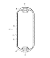
- FIG. 2 is a longitudinal sectional view showing an outline of the configuration of the gas tank 2.
- the gas tank 2 is formed, for example, in a substantially elliptical shape, and has a cylindrical body portion 2a having the same diameter, and a substantially hemispherical dome portion that is connected to both ends of the body portion 2a and decreases in diameter as the distance from the body portion 2a increases. 2b.
- a base 10 is provided at both ends of the gas tank 2 on the tank shaft.
- the base 10 is made of, for example, aluminum.
- the gas tank 2 has a substantially elliptical liner 20 inside.
- the liner 20 is made of a resin, for example, and is formed of a polyamide resin such as nylon 6 or nylon 6, 6 or a polyethylene resin.
- the liner 20 of the present embodiment is made of resin, but may be made of aluminum.
- the base 10 is fitted into the openings at both ends of the liner 20.
- a fiber reinforced resin layer 21 is formed so as to cover a part of the surface of the base 10 and almost the entire surface of the liner 20.
- the fiber reinforced resin layer 21 is formed by winding a fiber impregnated with a thermosetting resin around the base 10 and the liner 20 by, for example, a filament wiping (FW) method.
- the fiber reinforced resin layer 21 is composed of a plurality of layers having different winding directions, such as hoop winding and helical winding.
- a resin of the fiber reinforced resin layer 21 for example, an epoxy resin, a modified epoxy resin, an unsaturated polyester resin, or the like is used.
- carbon fiber is used, for example.
- the fiber impregnated with the thermosetting resin is wound around a part of the base 10 and the liner 20 by the FW method, and the fiber reinforced resin layer 21 is formed on the outer peripheral surface of the base 10 and the liner 20. At this time, hoop winding is always performed in a direction perpendicular to the tank axis.
- the fiber reinforced resin layer 21 is thermally cured by induction heating.
- the induction heating coil 30 is disposed around the liner 20.
- a heating shaft 31 as a heating means is attached to the liner 20 so as to be connected to the bases 10 on both sides.
- the heating shaft 31 incorporates a heater 32 such as a heating wire, and the heating shaft 31 generates heat by supplying power to the heater 32.
- attachment of this heating shaft 31 may be performed before the fiber reinforced resin layer 21 is formed, or may be performed after the fiber reinforced resin layer 21 is formed.
- the fiber reinforced resin layer 21 is induction heated by supplying power to the induction heating coil 30. Further, during this induction heating, power is supplied to the heater 32 and the base 10 is heated by the heating shaft 31.
- the temperature of the base 10 may be measured by a temperature sensor, the heating shaft 31 may generate heat based on the temperature, and the base 10 may be heated to an appropriate temperature.
- the base 10 when the fiber reinforced resin layer 21 is thermoset by induction heating, the base 10 is heated by the heating shaft 31 different from the induction heating, so that the heat of the fiber reinforced resin layer 21 is applied to the base 10. It can suppress deprivation. For this reason, the fiber reinforced resin layer 21 can be efficiently heated. Moreover, since the part which contact
- the base 10 is made of aluminum
- the liner 20 is made of resin. Since aluminum has a low dielectric constant, the base 10 is not induction-heated in this case.
- the resin liner 20 is induction heated. For this reason, it is considered that a large temperature difference occurs between the fiber reinforced resin layer 21 around the base 10 and the fiber reinforced resin layer 21 around the liner 20, thereby causing delamination in the fiber reinforced resin layer 21. It is done.
- the base 10 is heated by another heating means, the temperature difference between the fiber reinforced resin layer 21 around the base 10 and the fiber reinforced resin layer 21 around the liner 20 is small. Thus, delamination in the fiber reinforced resin layer 21 can be suppressed.
- the base 10 is heated by the heating shaft 31 when the fiber reinforced resin layer 21 is heated by induction heating.
- the base 10 is located between the base 10 and the fiber reinforced resin layer 21 rather than the base 10.
- a layer made of a material having a high dielectric constant may be formed.
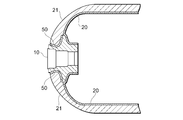
- a heating layer 50 made of, for example, an iron sheet having a high dielectric constant is formed in a portion of the base 10 that contacts the fiber reinforced resin layer 21.
- the heating layer 50 may have a thickness of 0.1 mm to 0.5 mm, for example. In this case, since the heating layer 50 is heated by induction heating, the heat of the fiber reinforced resin layer 21 is suppressed from being taken to the base 10 side.
- the fiber reinforced resin layer 21 can be heated more positively to heat the fiber reinforced resin layer 21 more efficiently.
- the material of the heating layer 50 is not limited to iron, but may be higher than the dielectric constant of the base 10. Other materials such as copper, gold, and silver may be used. A material having a dielectric constant of 300 W / mK or more is more preferable.
- a heat insulating layer may be formed between the base 10 and the fiber reinforced resin layer 21.
- a heat insulating layer 60 made of, for example, a urethane sheet is formed at a portion of the base 10 that contacts the fiber reinforced resin layer 21. Since the heat of the fiber reinforced resin layer 21 can be prevented from being taken away by the base 10 by the heat insulating layer 60, the fiber reinforced resin layer 21 can be heated uniformly and efficiently.
- the material of the heat insulation layer 60 may be another material.
- the heating means for heating the base 10 is the heating shaft 31, but may be a heating means having another configuration.
- the base 10 is heated by the heating means when the fiber reinforced resin layer 21 is thermoset.
- the base 10 is not heated and heated between the base 10 and the fiber reinforced resin layer 21.
- Only the layer 50 or the heat insulating layer 60 may be provided. That is, in the gas tank manufacturing method as a reference example, the fiber reinforced resin layer is thermally cured by induction heating in a state where a layer made of a material having a higher dielectric constant than the die is provided between the die and the fiber reinforced resin layer. You may make it have the process of thermosetting a fiber reinforced resin layer by induction heating in the state which has the process or provided the heat insulation layer between the nozzle
- the gas tank as a reference example may include a heating layer or a heat insulating layer made of a material having a dielectric constant higher than that of the base at least a part of the base (a part in contact with the fiber reinforced resin layer). Also according to these reference examples, since the heat of the fiber reinforced resin layer during induction heating is suppressed from being taken by the die, the fiber reinforced resin layer can be heated and cured uniformly and efficiently.
Landscapes
- Engineering & Computer Science (AREA)
- Mechanical Engineering (AREA)
- General Engineering & Computer Science (AREA)
- Moulding By Coating Moulds (AREA)
- Filling Or Discharging Of Gas Storage Vessels (AREA)
- Pressure Vessels And Lids Thereof (AREA)
Abstract
Description
2 ガスタンク
10 口金
20 ライナ
21 繊維強化樹脂層
30 誘導加熱コイル
31 加熱シャフト
32 ヒータ
50 加熱層
60 断熱層
Claims (4)
- ガスタンクの製造方法であって、
熱硬化性樹脂が含浸された繊維を口金の少なくとも一部とライナに巻回して繊維強化樹脂層を形成する工程と、
誘導加熱により前記繊維強化樹脂層を熱硬化する工程と、を有し、
前記繊維強化樹脂層を熱硬化する際に、前記誘導加熱と別の加熱手段により前記口金を加熱する、ガスタンクの製造方法。 - 前記口金と前記繊維強化樹脂層の間に、前記口金よりも誘電率の高い材料からなる層を設ける、請求項1に記載のガスタンクの製造方法。
- 前記口金と前記繊維強化樹脂層の間に断熱層を設ける、請求項1に記載のガスタンクの製造方法。
- 前記口金はアルミニウム製であり、前記ライナは樹脂製である、請求項1~3のいずれかに記載のガスタンクの製造方法。
Priority Applications (6)
| Application Number | Priority Date | Filing Date | Title |
|---|---|---|---|
| DE112011105278.2T DE112011105278B4 (de) | 2011-05-23 | 2011-05-23 | Herstellungsverfahren für einen Gastank |
| US14/119,577 US9211683B2 (en) | 2011-05-23 | 2011-05-23 | Method for manufacturing gas tank |
| PCT/JP2011/061777 WO2012160640A1 (ja) | 2011-05-23 | 2011-05-23 | ガスタンクの製造方法 |
| CA2836867A CA2836867C (en) | 2011-05-23 | 2011-05-23 | Method of manufacturing gas tank |
| CN201180071053.7A CN103562615B (zh) | 2011-05-23 | 2011-05-23 | 气罐的制造方法 |
| JP2013516098A JP5641268B2 (ja) | 2011-05-23 | 2011-05-23 | ガスタンクの製造方法 |
Applications Claiming Priority (1)
| Application Number | Priority Date | Filing Date | Title |
|---|---|---|---|
| PCT/JP2011/061777 WO2012160640A1 (ja) | 2011-05-23 | 2011-05-23 | ガスタンクの製造方法 |
Publications (1)
| Publication Number | Publication Date |
|---|---|
| WO2012160640A1 true WO2012160640A1 (ja) | 2012-11-29 |
Family
ID=47216743
Family Applications (1)
| Application Number | Title | Priority Date | Filing Date |
|---|---|---|---|
| PCT/JP2011/061777 Ceased WO2012160640A1 (ja) | 2011-05-23 | 2011-05-23 | ガスタンクの製造方法 |
Country Status (6)
| Country | Link |
|---|---|
| US (1) | US9211683B2 (ja) |
| JP (1) | JP5641268B2 (ja) |
| CN (1) | CN103562615B (ja) |
| CA (1) | CA2836867C (ja) |
| DE (1) | DE112011105278B4 (ja) |
| WO (1) | WO2012160640A1 (ja) |
Cited By (5)
| Publication number | Priority date | Publication date | Assignee | Title |
|---|---|---|---|---|
| JP2018159437A (ja) * | 2017-03-23 | 2018-10-11 | トヨタ自動車株式会社 | タンク製造用シャフト |
| JP2020116756A (ja) * | 2019-01-21 | 2020-08-06 | トヨタ自動車株式会社 | 高圧タンクの製造方法 |
| WO2021106745A1 (en) * | 2019-11-26 | 2021-06-03 | Government Of The United States, As Represented By The Secretary Of The Air Force | Fiber reinforced polymer composite structures and electromagnetic induction process for making same |
| US11193630B2 (en) | 2019-04-01 | 2021-12-07 | Toyota Jidosha Kabushiki Kaisha | High pressure tank and method for manufacturing the same |
| JP7643788B2 (ja) | 2021-03-29 | 2025-03-11 | 積水ソフランウイズ株式会社 | 防熱施工装置、及び防熱施工方法 |
Families Citing this family (6)
| Publication number | Priority date | Publication date | Assignee | Title |
|---|---|---|---|---|
| CN108430738A (zh) * | 2015-11-24 | 2018-08-21 | 昆腾燃料系统有限责任公司 | 具有内部负载支撑件的复合压力容器 |
| WO2017114880A1 (en) * | 2015-12-30 | 2017-07-06 | Arranged Bvba | Duplex constructive pressure vessel element |
| JP6939525B2 (ja) | 2017-12-25 | 2021-09-22 | トヨタ自動車株式会社 | 高圧タンクの製造方法 |
| JP2020034121A (ja) * | 2018-08-31 | 2020-03-05 | トヨタ自動車株式会社 | タンクの製造方法 |
| JP7528017B2 (ja) * | 2021-03-31 | 2024-08-05 | 本田技研工業株式会社 | 高圧タンクの製造方法及び高圧タンクの製造治具 |
| KR20230128774A (ko) * | 2022-02-28 | 2023-09-05 | 현대자동차주식회사 | 수소 압축 시스템 |
Citations (3)
| Publication number | Priority date | Publication date | Assignee | Title |
|---|---|---|---|---|
| JPH05329944A (ja) * | 1992-05-20 | 1993-12-14 | Mitsubishi Heavy Ind Ltd | 繊維強化プラスチック製品の製法 |
| JPH06335973A (ja) * | 1993-05-28 | 1994-12-06 | Sekisui Chem Co Ltd | 繊維強化樹脂積層体の製造方法 |
| JP2010071444A (ja) * | 2008-09-22 | 2010-04-02 | Toyota Motor Corp | 高圧タンクおよびその製造方法、製造装置 |
Family Cites Families (7)
| Publication number | Priority date | Publication date | Assignee | Title |
|---|---|---|---|---|
| US5356589A (en) * | 1993-03-09 | 1994-10-18 | Essef Corporation | Method and apparatus for forming rotationally cast tank liner having an end fitting |
| JPH07310895A (ja) * | 1994-05-17 | 1995-11-28 | Nippon Ekosu Kk | Frp外層を有する圧力容器 |
| US7763137B2 (en) * | 2003-02-03 | 2010-07-27 | Kyushu University, National University Corporation | Pressure shell, high-pressure tank provided with the pressure shell, manufacturing method of the high-pressure tank and manufacturing apparatus of the high-pressure tank |
| JP3527737B1 (ja) * | 2003-03-25 | 2004-05-17 | サムテック株式会社 | 高剛性繊維を用いた高圧タンク及びその製造方法 |
| JP4759729B2 (ja) * | 2005-04-20 | 2011-08-31 | 国立大学法人九州大学 | 高圧タンクの製造装置並びに高圧タンクの製造方法 |
| JP4457359B2 (ja) * | 2006-12-13 | 2010-04-28 | トヨタ自動車株式会社 | 圧力容器 |
| JP4552159B2 (ja) * | 2008-07-09 | 2010-09-29 | トヨタ自動車株式会社 | ガスタンク及びガスタンクの製造方法 |
-
2011
- 2011-05-23 JP JP2013516098A patent/JP5641268B2/ja active Active
- 2011-05-23 CN CN201180071053.7A patent/CN103562615B/zh active Active
- 2011-05-23 WO PCT/JP2011/061777 patent/WO2012160640A1/ja not_active Ceased
- 2011-05-23 US US14/119,577 patent/US9211683B2/en active Active
- 2011-05-23 DE DE112011105278.2T patent/DE112011105278B4/de active Active
- 2011-05-23 CA CA2836867A patent/CA2836867C/en active Active
Patent Citations (3)
| Publication number | Priority date | Publication date | Assignee | Title |
|---|---|---|---|---|
| JPH05329944A (ja) * | 1992-05-20 | 1993-12-14 | Mitsubishi Heavy Ind Ltd | 繊維強化プラスチック製品の製法 |
| JPH06335973A (ja) * | 1993-05-28 | 1994-12-06 | Sekisui Chem Co Ltd | 繊維強化樹脂積層体の製造方法 |
| JP2010071444A (ja) * | 2008-09-22 | 2010-04-02 | Toyota Motor Corp | 高圧タンクおよびその製造方法、製造装置 |
Cited By (7)
| Publication number | Priority date | Publication date | Assignee | Title |
|---|---|---|---|---|
| JP2018159437A (ja) * | 2017-03-23 | 2018-10-11 | トヨタ自動車株式会社 | タンク製造用シャフト |
| JP2020116756A (ja) * | 2019-01-21 | 2020-08-06 | トヨタ自動車株式会社 | 高圧タンクの製造方法 |
| US11027480B2 (en) | 2019-01-21 | 2021-06-08 | Toyota Jidosha Kabushiki Kaisha | Method for manufacturing high-pressure tank |
| JP7159882B2 (ja) | 2019-01-21 | 2022-10-25 | トヨタ自動車株式会社 | 高圧タンクの製造方法 |
| US11193630B2 (en) | 2019-04-01 | 2021-12-07 | Toyota Jidosha Kabushiki Kaisha | High pressure tank and method for manufacturing the same |
| WO2021106745A1 (en) * | 2019-11-26 | 2021-06-03 | Government Of The United States, As Represented By The Secretary Of The Air Force | Fiber reinforced polymer composite structures and electromagnetic induction process for making same |
| JP7643788B2 (ja) | 2021-03-29 | 2025-03-11 | 積水ソフランウイズ株式会社 | 防熱施工装置、及び防熱施工方法 |
Also Published As
| Publication number | Publication date |
|---|---|
| JP5641268B2 (ja) | 2014-12-17 |
| CA2836867C (en) | 2015-12-15 |
| CA2836867A1 (en) | 2012-11-29 |
| US20140096895A1 (en) | 2014-04-10 |
| US9211683B2 (en) | 2015-12-15 |
| JPWO2012160640A1 (ja) | 2014-07-31 |
| CN103562615B (zh) | 2015-12-16 |
| DE112011105278B4 (de) | 2016-03-17 |
| CN103562615A (zh) | 2014-02-05 |
| DE112011105278T5 (de) | 2014-02-27 |
Similar Documents
| Publication | Publication Date | Title |
|---|---|---|
| JP5641268B2 (ja) | ガスタンクの製造方法 | |
| JP5531040B2 (ja) | 高圧ガスタンクの製造方法 | |
| JP5468418B2 (ja) | 高圧タンクの製造装置並びに製造方法 | |
| JP4552159B2 (ja) | ガスタンク及びガスタンクの製造方法 | |
| US20160354970A1 (en) | Manufacturing method of tank | |
| JP2017110669A (ja) | タンクの製造方法およびタンク | |
| KR20190089880A (ko) | 섬유 보강 중합체 제조방법 | |
| JP5609249B2 (ja) | 高圧タンクの製造方法、高圧タンクの製造装置および高圧タンク | |
| JP5218889B2 (ja) | タンクの製造方法及び留め部材 | |
| JP4284705B2 (ja) | 成形体の製造方法、成形体、並びにタンク | |
| JP2010090938A (ja) | タンク及びタンクの製造方法 | |
| JP5257736B2 (ja) | タンクの製造方法及びタンクの製造設備 | |
| JP2017096334A (ja) | 高圧タンクの製造方法 | |
| JP2012148521A (ja) | タンクの製造方法及び製造装置 | |
| JP2011255581A (ja) | タンクの製造方法 | |
| JP2012066498A (ja) | ガスタンクの製造方法 | |
| JP5716905B2 (ja) | ガスタンクの製造方法及び熱硬化装置 | |
| JP2012076391A (ja) | ガスタンクの製造方法 | |
| JP5733681B2 (ja) | ガスタンク及びその製造方法 | |
| US11312062B2 (en) | High-pressure tank manufacturing method | |
| JP2018012235A (ja) | タンクの製造方法 | |
| JP2011230398A (ja) | 高圧ガスタンクの製造方法と製造装置 | |
| KR101919829B1 (ko) | 고압용기의 복합재 경화 장치 및 그 방법 | |
| JP2011235551A (ja) | 高圧タンクの製造方法および高圧タンクの製造装置 | |
| JP2017159499A (ja) | タンクの製造方法 |
Legal Events
| Date | Code | Title | Description |
|---|---|---|---|
| 121 | Ep: the epo has been informed by wipo that ep was designated in this application |
Ref document number: 11866112 Country of ref document: EP Kind code of ref document: A1 |
|
| ENP | Entry into the national phase |
Ref document number: 2013516098 Country of ref document: JP Kind code of ref document: A |
|
| ENP | Entry into the national phase |
Ref document number: 2836867 Country of ref document: CA |
|
| WWE | Wipo information: entry into national phase |
Ref document number: 14119577 Country of ref document: US |
|
| WWE | Wipo information: entry into national phase |
Ref document number: 1120111052782 Country of ref document: DE Ref document number: 112011105278 Country of ref document: DE |
|
| 122 | Ep: pct application non-entry in european phase |
Ref document number: 11866112 Country of ref document: EP Kind code of ref document: A1 |