WO2012157451A1 - 誘導回転電機 - Google Patents
誘導回転電機 Download PDFInfo
- Publication number
- WO2012157451A1 WO2012157451A1 PCT/JP2012/061570 JP2012061570W WO2012157451A1 WO 2012157451 A1 WO2012157451 A1 WO 2012157451A1 JP 2012061570 W JP2012061570 W JP 2012061570W WO 2012157451 A1 WO2012157451 A1 WO 2012157451A1
- Authority
- WO
- WIPO (PCT)
- Prior art keywords
- rotor
- electric machine
- stator
- notch
- induction rotating
- Prior art date
- Legal status (The legal status is an assumption and is not a legal conclusion. Google has not performed a legal analysis and makes no representation as to the accuracy of the status listed.)
- Ceased
Links
Images



Classifications
-
- H—ELECTRICITY
- H02—GENERATION; CONVERSION OR DISTRIBUTION OF ELECTRIC POWER
- H02K—DYNAMO-ELECTRIC MACHINES
- H02K17/00—Asynchronous induction motors; Asynchronous induction generators
- H02K17/02—Asynchronous induction motors
- H02K17/16—Asynchronous induction motors having rotors with internally short-circuited windings, e.g. cage rotors
- H02K17/20—Asynchronous induction motors having rotors with internally short-circuited windings, e.g. cage rotors having deep-bar rotors
Definitions
- the present invention relates to an induction rotating electrical machine such as a motor or a generator.
- Patent Document 1 discloses a technique for reducing the eddy current loss generated in the bar by providing an air gap on the outer diameter side.
- the induction rotating electric machine has a plurality of stator slots formed at predetermined intervals in the circumferential direction of the stator core, and the stator winding is accommodated in the plurality of stator slots.
- a stator, and a rotor provided with a plurality of rotor bars extending in the axial direction of the rotor core at predetermined intervals in the circumferential direction, and having a pair of end rings shorting the plurality of rotor bars at axial ends;
- the shape of the stator end of the cross-sectional shape in a plane orthogonal to the rotor axial direction of the rotor bar is asymmetric with respect to the radial axis passing through the rotor axial center and the axial center of the rotor bar.
- the notch is formed at the stator side end of the rotor bar and at a position shifted to the rotational rear side with respect to the radial axis.
- the notches are preferably formed along the eddy current density contours of the eddy currents generated when the rotor bar is in a symmetrical shape.
- the cross-sectional shape of the notch forms a curved curve in a circular arc shape.
- the notch of the notch has a curvature of the notch curve that is greater than the curvature of the rotation front side of the stator side end with respect to the radial axis Is also preferably set small.
- the notch in the induction rotating electrical machine according to any one of the first to fifth aspects, the notch extends from one axial end of the rotor bar to the other axial end Preferably, it is formed to
- the notch is preferably formed in a part of the rotor bar in the axial direction.
- the number of stator slots is s
- the permeability of the rotor bar is ⁇ (H / m)
- the notch is preferably filled with a nonmagnetic and nonconductive material.
- the eddy current loss in the rotor bar can be suppressed, and the efficiency of the induction rotating electrical machine can be improved.
- FIG. 1 is a block diagram showing a schematic configuration of a vehicle to which the induction rotating electrical machine of the present embodiment is applied.
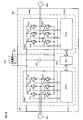
- FIG. 2 is a diagram showing the configuration of the inverter device INV.
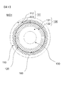
- FIG. 3 is a plan view showing the rotary electric machine MG1 of the present embodiment.
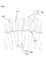
- FIG. 4 is an enlarged view of the facing portion of the stator 110 and the rotor 130.
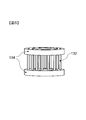
- FIG. 5 is a view showing the rotor bar 132 and the end ring 134.
- FIG. 6 is a diagram showing a current density distribution during powering.
- FIG. 7 is a diagram showing a current density distribution at the time of regeneration.
- FIG. 8 is a view showing an example of the shape of the notch 133. As shown in FIG. FIG. FIG.
- FIG. 9 is a view showing another example of the shape of the notch 133.
- FIG. 10 is a view showing another example of the shape of the notch 133.
- FIG. 11 is a perspective view of the rotor bar when the notch is provided in a part in the extending direction.
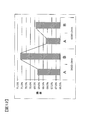
- FIG. 12 is a diagram showing the difference in the efficiency depending on the presence or absence of the notch 133.
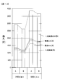
- FIG. 13 is a diagram showing the difference in loss depending on the presence or absence of the notch 133.
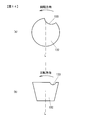
- FIG. 14 is a view showing another shape of the rotor bar 132. As shown in FIG.
- FIG. 1 is a block diagram showing a schematic configuration of a vehicle to which the induction rotating electrical machine of the present embodiment is applied.
- a hybrid electric vehicle having two different power sources will be described as an example.
- the hybrid electric vehicle according to the present embodiment is a four-wheel drive type configured to drive front wheels FLW and FRW by engine ENG, which is an internal combustion engine, and rotary electric machine MG1, and rear wheels RLW and RRW by rotary electric machine MG2. belongs to.
- the front wheels WFLW and FRW are driven by the engine ENG and the rotary electric machine MG1, and the rear wheels RLW and RRW are driven by the rotary electric machine MG2.
- the front wheels WFLW and FRW are generated by the rotary electric machine MG1 with the engine ENG.
- the rear wheels RLW and RRW may be driven by the rotary electric machine MG2, respectively.
- a transmission T / M is mechanically connected to front wheel axles FDS of the front wheels FLW and FRW via a differential FDF.
- the rotary electric machine MG1 and the engine ENG are mechanically connected to the transmission T / M via the power distribution mechanism PSM.
- the power distribution mechanism PSM is a mechanism that controls the synthesis and distribution of rotational drive forces.
- the alternating current side of the inverter device INV is electrically connected to the stator winding of the rotary electric machine MG1.
- the inverter device INV is a power conversion device that converts direct current power into three-phase alternating current power, and controls the drive of the rotating electrical machine MG1.
- a battery BAT is electrically connected to the DC side of the inverter device INV.
- the rotary electric machine MG2 is mechanically connected to the rear wheel axles RDS of the rear wheels RLW, RRW via a differential gear RDF and a reduction gear RG.
- the alternating current side of the inverter device INV is electrically connected to the stator winding of the rotary electric machine MG2.
- the inverter device INV is shared by the rotating electrical machines MG1 and MG2, and the power module PMU1 and the drive circuit device DCU1 for the rotating electrical machine MG1 and the power module PMU2 and the drive circuit device DCU2 for the rotating electrical machine MG2 And a motor control unit MCU.
- a starter STR is attached to the engine ENG.
- Starter STR is a starting device for starting engine ENG.
- the engine control unit ECU calculates control values for operating each component (engine valve, fuel injection valve, etc.) of the engine ENG based on input signals from sensors, other control devices, etc.
- the control value is output as a control signal to the drive device of each component device of the engine ENG.
- the operation of each component device of the engine ENG is controlled.
- the operation of the transmission T / M is controlled by a transmission control unit TCU.
- the transmission control device TCU calculates control values for operating the transmission mechanism based on input signals from sensors, other control devices, and the like.
- the control value is output as a control signal to the drive of the transmission mechanism.
- the operation of the transmission mechanism of the transmission T / M is controlled.
- the battery BAT is a high voltage lithium ion battery having a battery voltage of 200 V or more, and the battery control unit BCU manages charge and discharge, life, and the like.
- the voltage value and the current value of the battery BAT and the like are input to the battery control unit BCU in order to manage charge and discharge, life, and the like of the battery.
- a low voltage battery with a battery voltage of 12 V is also mounted as a battery, and is used as a power supply of a control system or a power supply such as a radio or a light.
- the engine control unit ECU, the transmission control unit TCU, the motor control unit MCU, and the battery control unit BCU are electrically connected to each other via the on-vehicle local area network LAN and electrically connected to the general control unit GCU. It is done. As a result, bidirectional signal transmission becomes possible between the control devices, and mutual information transmission, sharing of detection values, etc. become possible.
- the general control unit GCU outputs a command signal to each control unit according to the driving state of the vehicle. For example, the general control unit GCU calculates the required torque value of the vehicle according to the accelerator depression amount based on the driver's acceleration request.
- the general control unit GCU distributes this required torque value to the output torque value on the engine ENG side and the output torque value on the rotating electrical machine MG1 side so as to improve the operation efficiency of the engine ENG. Furthermore, general control unit GCU outputs the distributed output torque value on engine ENG side as an engine torque command signal to engine control unit ECU, and the distributed output torque value on rotating electric machine MG1 side as a motor torque command signal Output to the control unit MCU.
- the rotating electric machine MG1 drives the front wheels FLW and FRW.
- the rotating electric machine MG1 drives the front wheels FLW, FRW at the time of start-up and low-speed traveling of the hybrid electric vehicle.
- the rotating electric machine MG1 is used to drive the front wheels FLW, FRW.
- the rear wheels RLW and RRW may be driven according to (four-wheel drive travel may be performed).
- the inverter device INV is supplied with DC power from the battery BAT.
- the supplied DC power is converted into three-phase AC power by the inverter device INV.
- the three-phase AC power obtained thereby is supplied to the stator winding of the rotary electric machine MG1.
- the rotary electric machine MG1 is driven to generate a rotational output.
- This rotational output is input to the transmission T / M via the power distribution mechanism PSM.
- the input rotational output is shifted by the transmission T / M and input to the differential FDF.
- the input rotational output is distributed to the left and right by the differential device FDF, and transmitted to the left and right front wheel axles FDS.
- the front wheel axle FDS is rotationally driven.
- the front wheels FLW and FRW are rotationally driven by the rotational driving of the front wheel axle FDS.
- the engine ENG drives the front wheels FLW and FRW. Therefore, the rotational output of the engine ENG is input to the transmission T / M via the power distribution mechanism PSM. The input rotational output is shifted by the transmission T / M. The speed-changed rotational output is transmitted to the front wheel axle FDS via the differential FDF. As a result, the front wheels FLW and FRW are rotationally driven by the WH-F.
- the rotational output of engine ENG is distributed to rotary electric machine MG1 via power distribution mechanism PSM, and rotary electric machine MG1 is driven to rotate. .
- the rotary electric machine MG1 operates as a generator.
- three-phase AC power is generated in the stator winding of the rotary electric machine MG1.
- the generated three-phase AC power is converted into predetermined DC power by the inverter device INV.
- the DC power obtained by this conversion is supplied to the battery BAT. Thereby, the battery BAT is charged.
- the rear wheels RLW and RRW are To drive. Further, the front wheels FLW and FRW are driven by the engine ENG in the same manner as the normal traveling. Further, since the storage amount of the battery BAT is reduced by the driving of the rotary electric machine MG2, the rotary electric machine MG1 is rotationally driven by the rotational output of the engine ENG to charge the battery BAT, as in the normal traveling. In order to drive the rear wheels RLW and RRW by the rotary electric machine MG2, DC power is supplied to the inverter device INV from the battery BAT.
- the supplied DC power is converted into three-phase AC power by the inverter device INV, and the AC power obtained by this conversion is supplied to the stator winding of the rotary electric machine MG2.
- the rotary electric machine MG2 is driven to generate a rotational output.
- the generated rotational output is decelerated by the reduction gear RG and input to the differential gear RDF.
- the input rotational output is distributed to the left and right by the differential device RDF, and transmitted to the left and right rear wheel axles RDS respectively.
- the rear wheel axle RDS is rotationally driven.
- the rear wheels RLW and RRW are rotationally driven by the rotational drive of the rear wheel axle RDS.
- the front wheels FLW and FRW are driven by the engine ENG and the rotary electric machine MG1.
- the front wheels FLW and FRW are driven by the engine ENG and the rotating electric machine MG1 at the time of acceleration of the hybrid electric vehicle.
- the rear wheels RLW and RRW may be driven by the electric machine MG2 (four-wheel drive travel may be performed).
- the rotational outputs of the engine ENG and the rotary electric machine MG1 are input to the transmission T / M via the power distribution mechanism PSM.
- the input rotational output is shifted by the transmission T / M.
- the speed-changed rotational output is transmitted to the front wheel axle FDS via the differential FDF.
- the front wheels FLW and FRW are rotationally driven.
- the rotational force of the front wheels FLW, FRW is used as the front wheel axle FDS, differential FDF
- the transmission electric machine MG1 is transmitted to the electric rotating machine MG1 through the transmission T / M and the power distribution mechanism PSM, and the electric rotating machine MG1 is rotationally driven.
- the rotary electric machine MG1 operates as a generator.
- three-phase AC power is generated in the stator winding of the rotary electric machine MG1.
- the generated three-phase AC power is converted into predetermined DC power by the inverter device INV.
- the DC power obtained by this conversion is supplied to the battery BAT. Thereby, the battery BAT is charged.
- the rotational force of the rear wheels RLW and RRW is transmitted to the rotary electric machine MG2 via the rear wheel axles RDS, the differential device RDF, and the reduction gear RG, and the rotary electric machine MG2 is rotationally driven.
- the rotary electric machine MG2 operates as a generator.
- three-phase AC power is generated in the stator winding of the rotary electric machine MG2.
- the generated three-phase AC power is converted into predetermined DC power by the inverter device INV.
- the DC power obtained by this conversion is supplied to the battery BAT. Thereby, the battery BAT is charged.
- FIG. 2 shows the configuration of the inverter device INV in the present embodiment.
- the inverter device INV includes the power modules PMU1 and PMU2, the drive circuit devices DCU1 and DCU2, and the motor control device MCU.
- Power modules PMU1 and PMU2 have the same configuration.
- the drive circuit units DCU1 and DCU2 have the same configuration.
- the power modules PMU1 and PMU2 convert a DC power supplied from the battery BAT into AC power and configure a conversion circuit (also referred to as a main circuit) that supplies the AC power to the corresponding rotary electric machines MG1 and MG2.
- the conversion circuit can also convert AC power supplied from the corresponding rotary electric machines MG1 and MG2 into DC power and supply the DC power to the battery BAT.
- the conversion circuit is a bridge circuit, and a series circuit of three phases is electrically connected in parallel between the positive electrode side and the negative electrode side of the battery BAT.
- the series circuit is also called an arm, and is constituted by two semiconductor elements.
- the arm is configured such that the power semiconductor element on the upper arm side and the power semiconductor element on the lower arm side are electrically connected in series for each phase.
- an IGBT insulated gate bipolar transistor which is a switching semiconductor element is used as the power semiconductor element.
- the semiconductor chip constituting the IGBT is provided with three electrodes of a collector electrode, an emitter electrode and a gate electrode.
- a diode of a different chip from the IGBT is electrically connected between the collector electrode and the emitter electrode of the IGBT.
- the diode is electrically connected between the emitter electrode and the collector electrode of the IGBT such that the direction from the emitter electrode to the collector electrode of the IGBT is forward.
- a MOSFET metal oxide semiconductor type field effect transistor
- the emitter electrode of the power semiconductor device Tpu1 and the collector electrode of the power semiconductor device Tnu1 are electrically connected in series to configure a U-phase arm of the power module PMU1.
- the V-phase arm and the W-phase arm are also configured in the same manner as the U-phase arm.
- the V-phase arm of power module PMU1 is configured by electrically connecting the emitter electrode of power semiconductor element Tpv1 and the collector electrode of power semiconductor element Tnv1 in series.
- the emitter electrode of the power semiconductor device Tpw1 and the collector electrode of the power semiconductor device Tnw1 are electrically connected in series to configure the W-phase arm of the power module PMU1.
- the arms of each phase are configured in the same connection relationship as the power module PMU1 described above.
- the collector electrodes of the power semiconductor elements Tpu1, Tpv1, Tpw1, Tpu2, Tpv2 and Tpw2 are electrically connected to the high potential side (positive electrode side) of the battery BAT.
- Emitter electrodes of the power semiconductor elements Tnu1, Tnv1, Tnw1, Tnu2, Tnv2 and Tnw2 are electrically connected to the low potential side (negative electrode side) of the battery BAT.
- the middle point of the U-phase arm (V-phase arm, W-phase arm) of the power module PMU1 (the connection portion between the emitter electrode of the upper arm side power semiconductor device of each arm and the collector electrode of the lower arm side power semiconductor device) is rotated It is electrically connected to the U-phase (V-phase, W-phase) stator winding of the electric machine MG1.
- the middle point of the U-phase arm (V-phase arm, W-phase arm) of power module PMU2 (the connection portion between the emitter electrode of the upper arm side power semiconductor device of each arm and the collector electrode of the lower arm side power semiconductor device) is rotated It is electrically connected to the U-phase (V-phase, W-phase) stator winding of the electric machine MG2.
- a smoothing electrolytic capacitor SEC is electrically connected between the positive electrode side and the negative electrode side of the battery BAT in order to suppress the fluctuation of the direct current voltage caused by the operation of the power semiconductor element.
- the drive circuit units DCU1 and DCU2 output drive signals for operating the respective power semiconductor elements of the power modules PMU1 and PMU2 based on the control signal output from the motor control unit MCU, and operate the respective power semiconductor elements. And comprises circuit parts such as an insulated power supply, an interface circuit, a drive circuit, a sensor circuit, and a snubber circuit (all not shown).
- the motor control unit MCU is an arithmetic unit composed of a microcomputer, receives a plurality of input signals, and transmits control signals for operating the respective power semiconductor elements of the power modules PMU1 and PMU2 to the drive circuit units DSU1 and DSU2. Output.
- torque command values ⁇ * 1 and ⁇ * 2 current detection signals iu1 to iw1 and iu2 to iw2, and magnetic pole position detection signals ⁇ 1 and ⁇ 2 are input.
- the torque command values ⁇ * 1 and ⁇ * 2 are output from the upper control device according to the operation mode of the vehicle.
- the torque command value ⁇ * 1 corresponds to the rotary electric machine MG1
- the torque command value ⁇ * 2 corresponds to the rotary electric machine MG2.
- the current detection signals iu1 to iw1 are detection signals of the u-phase to w-phase input currents supplied from the conversion circuit of the inverter device INV to the stator windings of the rotary electric machine MG1, and the currents of current transformers (CT) etc. It is detected by a sensor.
- the current detection signals iu2 to iw2 are detection signals of the u-phase to w-phase input current supplied from the inverter device INV to the stator winding of the rotary electric machine MG2, and are detected by a current sensor such as a current transformer (CT) It is done.
- a current sensor such as a current transformer (CT) It is done.
- the magnetic pole position detection signal ⁇ 1 is a detection signal of the magnetic pole position of the rotation of the rotary electric machine MG1, and is detected by a magnetic pole position sensor such as a resolver, an encoder, a Hall element, or a Hall IC.
- the magnetic pole position detection signal ⁇ 2 is a detection signal of the magnetic pole position of the rotation of the rotary electric machine MG1, and is detected by a magnetic pole position sensor such as a resolver, an encoder, a Hall element, or a Hall IC.
- the motor control unit MCU calculates a voltage control value based on the input signal, and the voltage control value is used as a control signal (PWM signal for operating the power semiconductor elements Tpu1 to Tnw1 and Tpu2 to Tnw2 of the power modules PMU1 and PMU2). (Pulse width modulation signal) is output to the drive circuit units DCU1 and DCU2.
- the PWM signal output from the motor control unit MCU is such that the time-averaged voltage becomes a sine wave.
- the instantaneous maximum output voltage is the voltage of the DC line which is the input of the inverter, when outputting a sine wave voltage, its effective value is 1 / ⁇ 2. Therefore, in the hybrid electric vehicle according to the present embodiment, the effective value of the input voltage of the motor is increased in order to further increase the output of the motor with a limited inverter device. That is, the PWM signal of the MCU is made to be ON and OFF only in a rectangular wave form. In this case, the peak value of the rectangular wave becomes the voltage Vdc of the DC line of the inverter, and the effective value thereof becomes Vdc. This is the method of maximizing the voltage effective value.
- the rectangular wave voltage has a problem that the current waveform is disturbed because the inductance is small in the low rotation speed region, and this generates unnecessary vibrational force in the motor to generate noise. Therefore, square wave voltage control is used only at high speed rotation, and normal PWM control is performed at low frequency.
- FIG. 3 is a plan view showing the rotary electric machine MG1 of the present embodiment.
- FIG. 4 is an enlarged view of the facing portion of the stator 110 and the rotor 130 of FIG.
- symbol is attached
- rotary electric machine MG1 is demonstrated, rotary electric machine MG2 is also the same structure.
- Rotary electric machine MG1 is provided with a stator 110 generating a rotating magnetic field, and a rotor 130 rotatably disposed on the inner circumferential side of stator 110 with air gap 160 interposed therebetween and rotating by magnetic action with stator 110. And have.
- the stator 110 includes a stator core 111 composed of a core back 112 and teeth 113, and a slot 114 for inserting a stator winding 120 for generating a magnetic flux by energization.
- the stator core 111 is formed by axially stacking a plurality of plate-like molded members formed by punching out a plate-like magnetic member. Or you may form by cast iron.
- the axial direction means a direction along the rotation axis of the rotor 130.
- the stator winding 120 is wound around the teeth 113 by being inserted into the slot 114.
- the rotor 130 includes a rotor core 131 constituting a magnetic path on the rotation side, a rotor bar 132 made of nonmagnetic and conductive metal such as aluminum or copper, and a shaft (not shown) serving as a rotation axis. There is.
- the rotor bar 132 extends in the axial direction of the rotor 130, and as shown in FIG. 5, an end ring 134 is provided for shorting the rotor bar 132 at the axial end.
- a notch 133 is formed on the outer diameter side (the stator side end portion region) of the rotor bar 132. As described later, by providing the notches 133 in the rotor bar 132, the efficiency of the rotary electric machine MG1 can be improved.
- FIG. 6 and 7 show the analysis results of the current density distribution generated in the rotor bar 132 by the finite element method. Both show the case where the notch 133 is not provided, that is, the case where the cross-sectional shape of the rotor bar 132 is symmetrical with respect to the axis L, FIG. 6 shows the current density distribution during powering, and FIG. 7 shows the current density distribution during regeneration.
- the axis L is a radial straight line passing through the axis of the rotor 130 and the axis of the rotor bar 132.
- the broken line shows the cross-sectional shape of the rotor bar 132, and the solid line shows the contour of the current density.
- Arrow R indicates the rotational direction of the rotor.
- the rotation direction here refers to the main rotation direction (forward rotation) when using a rotary electric machine. In a rotating electrical machine mounted on a vehicle, the direction of rotation when advancing the vehicle is the main direction of rotation.
- the slots 114 are formed in the stator core 111, so that the magnetic resistance differs between the portions of the slots 114 and the portions of the teeth 113. Therefore, the magnetic flux density of the magnetic flux linked to the rotor bar 132 largely changes depending on whether the rotor bar 132 rotating with the rotor 130 is in the vicinity of the teeth and in the vicinity of the slot. Generally, this is called slot harmonics. As a result, a current (eddy current) flows through the rotor bar 132 so as to cancel the change in the magnetic flux. This current is generated on the outer peripheral side of the rotor bar 132. This can be understood from the fact that the current density is high on the outer peripheral side of the rotor bar 132 as shown in FIGS. However, this current is a current associated with the slot harmonics and does not contribute to the torque.
- the notch 133 in a shape including a region where the eddy current on the rear side in the rotational direction is concentrated.
- the rotor bar 132 is symmetrical in the left-right direction, and the axial center of the rotor bar 132 exists on the symmetry axis. That is, in the present embodiment, by forming the notch 133 on the rotational rear side, the cross-sectional shape of the rotor bar 132 is left-right asymmetric.
- the shape of the notch 133 for example, it is preferable to have a shape that follows the contour line CL of the current density obtained by analysis, as in a curve indicated by the symbol S in FIG.
- the shape of the notch line S formed in the outer peripheral side tip region of the rotor bar 132 becomes a substantially arc-shaped depressed curve, and its position (the position of the central portion of the notch 133) rotates backward with respect to the axis L It is off to the side.
- the depth of the notch 133 and the amount of deviation from the axis L toward the rear of the rotation may be determined based on the above-described current density analysis result.
- the depth D of the notch 133 is preferably set in accordance with the depth of the distribution where the harmonic eddy current loss occurs. Since the magnetic flux penetration depth ⁇ in the rotor bar 132 is expressed by the following equation (1), it may be set as D ⁇ ⁇ . Where ⁇ : frequency of magnetic flux [rad / s], ⁇ : conductivity of bar [S / m], ⁇ : bar permeability [H / m].
- the notch shape may be as shown in FIGS. 9 and 10 in consideration of ease of processing.
- the notch line S is a straight line.
- the notch line S is convex outward, and the curvature thereof is smaller than the curvature of the tip portion S1 on the left side (rotation front side) of the axis L. In either case, since the region where the current density is concentrated is cut out, it is possible to reduce the eddy current loss due to the slot harmonics.
- the notches 133 are formed from one end to the other end along the extending direction of the rotor bar 132, but as shown in FIG. You may do it.
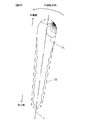
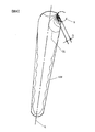
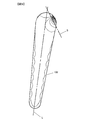
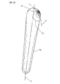
- FIG. 14 (a) shows a notch 133 formed on a rotor bar 132 having a circular cross-sectional shape
- FIG. 14 (b) shows a notch 133 formed on a rotor bar 132 having a trapezoidal cross-sectional shape. Both of them are the stator side end portions, and the notches 133 are formed so as to be shifted to the rotational rear side with respect to the axis L.
- FIG. 12 shows the efficiency under each of the conditions, and the efficiency is improved when the notch 133 shown in B is provided at any rotation speed of 3400 r / min and 6000 r / min.
- FIG. 13 shows the breakdown of losses in each case.
- the eddy current loss generated in the rotor bar 132 is included in a loss called secondary copper loss. According to FIG. 13, the secondary copper loss is reduced by providing the notches 133 in the rotor bar 132.
- a motor for a hybrid electric vehicle or the like is required to be downsized in order to be mounted in an engine room, but using the rotating electric machine of the present embodiment provides torque compared to a rotating electric machine of the same size Improvement is possible. That is, according to the present invention, downsizing of the motor size can be achieved.
- the air gap (air gap including the notch 133) is provided at the end of the rotor bar in the present invention, but if it is nonmagnetic and nonconductive, it is filled with resin or a substance mainly containing silicon. It does not matter.
- the air gap may be left as it is, but when the rotor bar 132 and the end ring 134 are formed by die casting, the notch 133 at the tip of the rotor bar is nonmagnetic And it is more desirable to make it die-cast in the state where it was filled up with the nonconductive material.
- the eddy current loss can be reduced and the torque can be improved.
- the inner rotor type rotating electrical machine has been described as an example in each of the embodiments described above, the present invention can be applied to an outer rotor type rotating electrical machine.
- Each of the embodiments described above may be used alone or in combination. This is because the effects of the respective embodiments can be exhibited singly or synergistically. Further, the present invention is not limited to the above-described embodiment as long as the features of the present invention are not impaired.
Landscapes
- Engineering & Computer Science (AREA)
- Power Engineering (AREA)
- Electric Propulsion And Braking For Vehicles (AREA)
- Induction Machinery (AREA)
Abstract
Description
本発明の第2の態様によると、第1の態様の誘導回転電機において、ロータバーの固定子側端部であって径方向軸線に関して回転後方側にずれた位置に、切り欠きを形成するのが好ましい。
本発明の第3の態様によると、第2の態様の誘導回転電機において、切り欠きを、ロータバーが対称形状であるときに発生する渦電流の渦電流密度等高線に沿って形成するのが好ましい。
本発明の第4の態様によると、第2の態様の誘導回転電機において、切り欠きの断面形状は、円弧状に窪んだ曲線を形成するのが好ましい。
本発明の第5の態様によると、第2の態様の誘導回転電機において、切り欠きの断面形状は、切り欠き曲線の曲率が、径方向軸線に関して固定子側端部の回転前方側の曲率よりも小さく設定されているのが好ましい。
本発明の第6の態様によると、第1乃至5のいずれか一の態様に記載の誘導回転電機において、切り欠きは、ロータバーの一方の軸方向端部から他方の軸方向端部まで延在するように形成されているのが好ましい。
本発明の第7の態様によると、第1乃至5のいずれか一の態様に記載の誘導回転電機において、切り欠きは、ロータバーの軸方向の一部に形成されているのが好ましい。
本発明の第8の態様によると、第1乃至5のいずれか一の態様に記載の誘導回転電機において、固定子スロットの数をs、ロータバーの透磁率をμ(H/m)、ロータバーの導電率σ(S/m)、回転子の回転数をN(r/min)としたとき、切り欠きの深さδ(m)をδ=√{2/(2πNsσμ/60)}と設定するのが好ましい。
本発明の第9の態様によると、第1乃至5のいずれか一の態様に記載の誘導回転電機において、切り欠きに、非磁性で且つ非導電性の材料を充填するのが好ましい。
δ=√{2/(ωσμ)} …(1)
日本国特許出願2011年第108234号(2011年5月13日出願)
Claims (9)
- 固定子鉄心の周方向に所定間隔で形成された複数の固定子スロットを有し、前記複数の固定子スロットに固定子巻線が納められた固定子と、
前記回転子鉄心の軸方向に延在するロータバーが周方向に所定間隔で複数設けられ、前記複数のロータバーを軸方向端部で短絡する一対のエンドリングが設けられた回転子と、を備え、
前記ロータバーの回転子軸方向に直交する面内における断面形状のうち固定子側端部の形状が、回転子軸芯と前記ロータバーの軸芯とを通る径方向軸線に関して非対称である誘導回転電機。 - 請求項1に記載の誘導回転電機において、
前記ロータバーの固定子側端部であって前記径方向軸線に関して回転後方側にずれた位置に、切り欠きを形成した誘導回転電機。 - 請求項2に記載の誘導回転電機において、
前記切り欠きを、前記ロータバーが対称形状であるときに発生する渦電流の渦電流密度等高線に沿って形成したことを特徴とする誘導回転電機。 - 請求項2に記載の誘導回転電機において、
前記切り欠きの断面形状は、円弧状に窪んだ曲線を形成している誘導回転電機。 - 請求項2に記載の誘導回転電機において、
前記切り欠きの断面形状は、切り欠き曲線の曲率が、前記径方向軸線に関して前記固定子側端部の回転前方側の曲率よりも小さく設定されている誘導回転電機。 - 請求項1乃至5のいずれか一項に記載の誘導回転電機において、
前記切り欠きは、前記ロータバーの一方の軸方向端部から他方の軸方向端部まで延在するように形成されている誘導回転電機。 - 請求項1乃至5のいずれか一項に記載の誘導回転電機において、
前記切り欠きは、前記ロータバーの軸方向の一部に形成されている誘導回転電機。 - 請求項1乃至5のいずれか一項に記載の誘導回転電機において、
前記固定子スロットの数をs、前記ロータバーの透磁率をμ(H/m)、前記ロータバーの導電率σ(S/m)、前記回転子の回転数をN(r/min)としたとき、前記切り欠きの深さδ(m)をδ=√{2/(2πNsσμ/60)}と設定した誘導回転電機。 - 請求項1乃至5のいずれか一項に記載の誘導回転電機において、
前記切り欠きに、非磁性で且つ非導電性の材料を充填した誘導回転電機。
Priority Applications (3)
| Application Number | Priority Date | Filing Date | Title |
|---|---|---|---|
| CN201280020956.7A CN103503285B (zh) | 2011-05-13 | 2012-05-01 | 感应旋转电机 |
| DE112012002067.7T DE112012002067T5 (de) | 2011-05-13 | 2012-05-01 | Elektrische Induktions-Rotationsmaschine |
| US14/114,297 US20140049134A1 (en) | 2011-05-13 | 2012-05-01 | Induction electrical rotating machine |
Applications Claiming Priority (2)
| Application Number | Priority Date | Filing Date | Title |
|---|---|---|---|
| JP2011-108234 | 2011-05-13 | ||
| JP2011108234A JP5722116B2 (ja) | 2011-05-13 | 2011-05-13 | 誘導回転電機 |
Publications (1)
| Publication Number | Publication Date |
|---|---|
| WO2012157451A1 true WO2012157451A1 (ja) | 2012-11-22 |
Family
ID=47176786
Family Applications (1)
| Application Number | Title | Priority Date | Filing Date |
|---|---|---|---|
| PCT/JP2012/061570 Ceased WO2012157451A1 (ja) | 2011-05-13 | 2012-05-01 | 誘導回転電機 |
Country Status (5)
| Country | Link |
|---|---|
| US (1) | US20140049134A1 (ja) |
| JP (1) | JP5722116B2 (ja) |
| CN (1) | CN103503285B (ja) |
| DE (1) | DE112012002067T5 (ja) |
| WO (1) | WO2012157451A1 (ja) |
Families Citing this family (10)
| Publication number | Priority date | Publication date | Assignee | Title |
|---|---|---|---|---|
| JP6131722B2 (ja) * | 2013-06-04 | 2017-05-24 | マツダ株式会社 | 誘導モータ |
| CN105656255B (zh) * | 2014-12-01 | 2019-10-08 | 特斯拉公司 | 转子端环和定子端匝的几何形状 |
| CN105680598A (zh) * | 2016-04-19 | 2016-06-15 | 江苏华源防爆电机有限公司 | 电动车的动力系统 |
| PT3588753T (pt) * | 2018-06-29 | 2021-05-14 | Abb Schweiz Ag | Máquina de indução elétrica |
| CN111082608B (zh) * | 2019-11-26 | 2020-11-24 | 华北电力大学 | 一种高压大功率笼型电机转子铜条消谐槽加工方法 |
| CN112117844B (zh) * | 2020-09-14 | 2021-10-08 | 珠海格力电器股份有限公司 | 电机及具有其的螺杆压缩机 |
| EP4262066A4 (en) * | 2020-12-11 | 2024-02-07 | Weg Equipamentos Electricos S.A. | ROTOR FOR ELECTRIC LATHE, PRODUCTION METHOD AND CORRESPONDING ELECTRIC LATHE |
| DE102022208673A1 (de) | 2022-08-22 | 2024-02-22 | Volkswagen Aktiengesellschaft | Verfahren zur Fertigung eines Läufers einer elektrischen Maschine |
| KR20250105424A (ko) * | 2022-12-12 | 2025-07-08 | 닛폰세이테츠 가부시키가이샤 | 로터, 로터 코어, 유도 모터, 및 유도 모터의 설계 방법 |
| DE102023201638A1 (de) | 2023-02-23 | 2024-08-29 | Volkswagen Aktiengesellschaft | Rotor, Asynchronmaschine und Kraftfahrzeug |
Citations (3)
| Publication number | Priority date | Publication date | Assignee | Title |
|---|---|---|---|---|
| JPS602379U (ja) * | 1983-06-15 | 1985-01-09 | 株式会社安川電機 | 回転電機の回転子 |
| JPH03285543A (ja) * | 1990-03-30 | 1991-12-16 | Toshiba Corp | かご形回転子 |
| WO2012077171A1 (ja) * | 2010-12-06 | 2012-06-14 | 三菱電機株式会社 | 誘導電動機及び圧縮機及び送風機及び空気調和機 |
Family Cites Families (8)
| Publication number | Priority date | Publication date | Assignee | Title |
|---|---|---|---|---|
| GB1044574A (en) * | 1964-04-17 | 1966-10-05 | Lancashire Dynamo And Crypto L | Improvements in or relating to rotary electric machines |
| US4801832A (en) * | 1987-11-04 | 1989-01-31 | General Electric Company | Stator and rotor lamination construction for a dynamo-electric machine |
| US5182483A (en) * | 1989-12-28 | 1993-01-26 | Kabushiki Kaisha Toshiba | Squirrel-cage rotor with shaped-conductor harmonic reduction |
| JPH08237919A (ja) * | 1995-02-24 | 1996-09-13 | Fanuc Ltd | 誘導電動機の籠形回転子 |
| JPH1052013A (ja) * | 1996-08-01 | 1998-02-20 | Hitachi Ltd | 誘導電動機 |
| US5886443A (en) * | 1997-12-03 | 1999-03-23 | General Electric Canada Inc. | Spark suppression of induction type rotors of dynamoelectric machines |
| DE10309161A1 (de) * | 2003-02-28 | 2004-09-16 | Siemens Ag | Elektrische Maschine mit geblechtem Läufer |
| JP4408869B2 (ja) * | 2006-03-15 | 2010-02-03 | ジヤトコ株式会社 | 誘導電動機の籠形回転子 |
-
2011
- 2011-05-13 JP JP2011108234A patent/JP5722116B2/ja active Active
-
2012
- 2012-05-01 DE DE112012002067.7T patent/DE112012002067T5/de active Pending
- 2012-05-01 WO PCT/JP2012/061570 patent/WO2012157451A1/ja not_active Ceased
- 2012-05-01 US US14/114,297 patent/US20140049134A1/en not_active Abandoned
- 2012-05-01 CN CN201280020956.7A patent/CN103503285B/zh active Active
Patent Citations (3)
| Publication number | Priority date | Publication date | Assignee | Title |
|---|---|---|---|---|
| JPS602379U (ja) * | 1983-06-15 | 1985-01-09 | 株式会社安川電機 | 回転電機の回転子 |
| JPH03285543A (ja) * | 1990-03-30 | 1991-12-16 | Toshiba Corp | かご形回転子 |
| WO2012077171A1 (ja) * | 2010-12-06 | 2012-06-14 | 三菱電機株式会社 | 誘導電動機及び圧縮機及び送風機及び空気調和機 |
Also Published As
| Publication number | Publication date |
|---|---|
| CN103503285B (zh) | 2016-02-03 |
| US20140049134A1 (en) | 2014-02-20 |
| JP5722116B2 (ja) | 2015-05-20 |
| DE112012002067T5 (de) | 2014-03-06 |
| JP2012239352A (ja) | 2012-12-06 |
| CN103503285A (zh) | 2014-01-08 |
Similar Documents
| Publication | Publication Date | Title |
|---|---|---|
| JP5722116B2 (ja) | 誘導回転電機 | |
| JP6147661B2 (ja) | 回転子、およびこれを備えた永久磁石式回転電機、電動駆動システム、電動車両 | |
| JP4740273B2 (ja) | 回転電機およびそれを用いたハイブリッド自動車 | |
| JP4668721B2 (ja) | 永久磁石式回転電機 | |
| JP5745379B2 (ja) | 回転電機および電動車両 | |
| JP5948127B2 (ja) | 永久磁石回転電機及びそれを用いた電動車両 | |
| JP5742850B2 (ja) | 回転電機システム | |
| US9692261B2 (en) | Rotating electric machine and electrically driven vehicle | |
| US9787144B2 (en) | Rotating electrical motor using transverse magnetic flux | |
| CN100576701C (zh) | 永磁式旋转电机 | |
| JP6158022B2 (ja) | 回転電機、及び車輌 | |
| CN113016121A (zh) | 旋转电机及汽车用电动辅机系统 | |
| WO2014188757A1 (ja) | 回転電機の回転子、回転電機、電動駆動システム、及び電動車両 | |
| CN108111089B (zh) | 开关磁阻马达用的控制装置 | |
| WO2013129024A1 (ja) | 誘導電動機、電動駆動システム及びそれらを備えた電動車両 | |
| JP5572508B2 (ja) | 回転電機 | |
| CN102275523A (zh) | 车辆以及用于控制车辆的设备和方法 | |
| JP2020043742A (ja) | 電動発電機の制御装置 |
Legal Events
| Date | Code | Title | Description |
|---|---|---|---|
| 121 | Ep: the epo has been informed by wipo that ep was designated in this application |
Ref document number: 12785123 Country of ref document: EP Kind code of ref document: A1 |
|
| WWE | Wipo information: entry into national phase |
Ref document number: 14114297 Country of ref document: US |
|
| WWE | Wipo information: entry into national phase |
Ref document number: 112012002067 Country of ref document: DE Ref document number: 1120120020677 Country of ref document: DE |
|
| 122 | Ep: pct application non-entry in european phase |
Ref document number: 12785123 Country of ref document: EP Kind code of ref document: A1 |