WO2012157445A1 - 電力供給制御装置及びその制御方法、並びに電力供給制御システム - Google Patents
電力供給制御装置及びその制御方法、並びに電力供給制御システム Download PDFInfo
- Publication number
- WO2012157445A1 WO2012157445A1 PCT/JP2012/061527 JP2012061527W WO2012157445A1 WO 2012157445 A1 WO2012157445 A1 WO 2012157445A1 JP 2012061527 W JP2012061527 W JP 2012061527W WO 2012157445 A1 WO2012157445 A1 WO 2012157445A1
- Authority
- WO
- WIPO (PCT)
- Prior art keywords
- information
- power
- electronic device
- power supply
- user
- Prior art date
- Legal status (The legal status is an assumption and is not a legal conclusion. Google has not performed a legal analysis and makes no representation as to the accuracy of the status listed.)
- Ceased
Links
Images


Classifications
-
- H—ELECTRICITY
- H04—ELECTRIC COMMUNICATION TECHNIQUE
- H04B—TRANSMISSION
- H04B3/00—Line transmission systems
- H04B3/54—Systems for transmission via power distribution lines
- H04B3/546—Combination of signalling, telemetering, protection
-
- G—PHYSICS
- G01—MEASURING; TESTING
- G01D—MEASURING NOT SPECIALLY ADAPTED FOR A SPECIFIC VARIABLE; ARRANGEMENTS FOR MEASURING TWO OR MORE VARIABLES NOT COVERED IN A SINGLE OTHER SUBCLASS; TARIFF METERING APPARATUS; MEASURING OR TESTING NOT OTHERWISE PROVIDED FOR
- G01D2204/00—Indexing scheme relating to details of tariff-metering apparatus
- G01D2204/10—Analysing; Displaying
- G01D2204/12—Determination or prediction of behaviour, e.g. likely power consumption or unusual usage patterns
-
- H—ELECTRICITY
- H04—ELECTRIC COMMUNICATION TECHNIQUE
- H04B—TRANSMISSION
- H04B2203/00—Indexing scheme relating to line transmission systems
- H04B2203/54—Aspects of powerline communications not already covered by H04B3/54 and its subgroups
- H04B2203/5429—Applications for powerline communications
- H04B2203/5433—Remote metering
-
- Y—GENERAL TAGGING OF NEW TECHNOLOGICAL DEVELOPMENTS; GENERAL TAGGING OF CROSS-SECTIONAL TECHNOLOGIES SPANNING OVER SEVERAL SECTIONS OF THE IPC; TECHNICAL SUBJECTS COVERED BY FORMER USPC CROSS-REFERENCE ART COLLECTIONS [XRACs] AND DIGESTS
- Y02—TECHNOLOGIES OR APPLICATIONS FOR MITIGATION OR ADAPTATION AGAINST CLIMATE CHANGE
- Y02B—CLIMATE CHANGE MITIGATION TECHNOLOGIES RELATED TO BUILDINGS, e.g. HOUSING, HOUSE APPLIANCES OR RELATED END-USER APPLICATIONS
- Y02B90/00—Enabling technologies or technologies with a potential or indirect contribution to GHG emissions mitigation
- Y02B90/20—Smart grids as enabling technology in buildings sector
-
- Y—GENERAL TAGGING OF NEW TECHNOLOGICAL DEVELOPMENTS; GENERAL TAGGING OF CROSS-SECTIONAL TECHNOLOGIES SPANNING OVER SEVERAL SECTIONS OF THE IPC; TECHNICAL SUBJECTS COVERED BY FORMER USPC CROSS-REFERENCE ART COLLECTIONS [XRACs] AND DIGESTS
- Y04—INFORMATION OR COMMUNICATION TECHNOLOGIES HAVING AN IMPACT ON OTHER TECHNOLOGY AREAS
- Y04S—SYSTEMS INTEGRATING TECHNOLOGIES RELATED TO POWER NETWORK OPERATION, COMMUNICATION OR INFORMATION TECHNOLOGIES FOR IMPROVING THE ELECTRICAL POWER GENERATION, TRANSMISSION, DISTRIBUTION, MANAGEMENT OR USAGE, i.e. SMART GRIDS
- Y04S20/00—Management or operation of end-user stationary applications or the last stages of power distribution; Controlling, monitoring or operating thereof
- Y04S20/30—Smart metering, e.g. specially adapted for remote reading
Definitions
- the present technology relates to a power supply control device, a control method thereof, and a power supply control system, and more particularly, to a power supply control device, a control method thereof, and a power supply control system capable of easily performing user registration.
- a method for creating and registering a warranty is proposed in which a warranty card is created and registered by accessing the site for creating and registering a warranty card from a mobile terminal device in accordance with the access information of a barcode or IC tag attached to the product. (For example, refer to Patent Document 1).
- This technology has been made in view of such a situation, and makes it possible to easily perform user registration.
- the power supply control device communicates with a power supply unit that outputs power via a power line, an electronic device that outputs power, and outputs a high-frequency signal via the power line.
- the communication unit that reads out device information including at least identification information for identifying the electronic device, the control unit that acquires user information regarding the user who uses the electronic device, and the acquired user information are read out.
- a transmission unit that transmits the device information to an information management device that manages the device information.
- a recording unit configured to record the user information; and when the user information is not recorded in the recording unit, the control unit acquires the user information input by a user, and the user information is stored in the recording unit. If the user information is recorded, the recorded user information is acquired.
- the control unit performs authentication processing of the electronic device based on the identification information included in the read device information, and outputs to the electronic device via the power line according to a result of the authentication processing Control the power generated.
- the communication unit obtains usage history information related to the usage status of the electronic device by outputting a high-frequency signal via the power line for communication, and the transmission unit acquires the acquired usage history information as the Along with the device information, the information is transmitted to the information management apparatus.
- the communication unit acquires the power usage time and the power consumption of the electronic device as the usage history information.
- the electronic device is provided with a storage element that outputs the stored device information to the power supply control device via the power line by load-modulating a high-frequency signal input via the power line.
- the control method according to the first aspect of the present technology is a control method corresponding to the power supply control device according to the first aspect of the present technology described above.
- power is output via the power line, and communication is performed by outputting a high-frequency signal via the power line with the electronic device from which the power is output.
- Device information including at least identification information for identifying an electronic device is read, user information regarding a user who uses the electronic device is acquired, and the acquired user information is managed together with the read device information. To the information management device.
- a power supply control system is a power supply control system including an electronic device, a power supply control device, an information management device, and a terminal device.
- the power supply control device supplies power via a power line.
- a communication unit that reads out device information including at least identification information for identifying the electronic device by outputting a high-frequency signal via the power line and communicating with the power supply unit that outputs power and the electronic device that outputs power
- a control unit that acquires user information regarding a user who uses the electronic device, and a transmission unit that transmits the acquired user information together with the read device information to the information management device
- An information management device includes: a receiving unit that receives the user information and the device information transmitted from the power supply control device; and the received user information Based on, and a processing unit that performs user registration processing relating to the electronic device identified by the identification information included in the device information.
- the information management device further includes a recording unit that records the received device information, and the processing unit performs a process of providing the recorded device information in response to a request from the terminal device.
- the communication unit obtains usage history information related to the usage status of the electronic device by outputting a high-frequency signal via the power line for communication, and the transmission unit acquires the acquired usage history information as the The information is transmitted to the information management device together with the device information, and the reception unit receives the usage history information and the device information transmitted from the power supply control device, and the recording unit receives the received usage The history information and the device information are recorded in association with each other.
- the communication unit acquires the power usage time and the power consumption of the electronic device as the usage history information.
- the processing unit performs a process of providing the recorded usage history information in response to a request from the terminal device.
- the electronic device includes a storage element that outputs the stored device information to the power supply control device via the power line by load-modulating a high-frequency signal input via the power line.
- the electronic device, power supply control device, information management device, and terminal device may be independent devices or may be internal blocks constituting one device.
- the power supply control device outputs power through the power line, and communicates with the electronic device from which the power is output by outputting a high-frequency signal through the power line.
- device information including at least identification information for identifying the electronic device is read, user information regarding a user who uses the electronic device is acquired, and the acquired user information is information together with the read device information.
- Electronic information that is transmitted to the management device and received by the information management device from the power supply control device is received by the identification information included in the device information based on the received user information.
- User registration processing related to the device is performed.
- user registration can be performed easily.
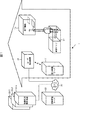
- FIG. 1 is a diagram illustrating a configuration example of a power supply control system.
- the power supply control system 1 includes a power control server 11, a power strip 12, an electronic device 13, a user terminal device 14, an information management server 21, and information use terminal devices 22-1 to 22-3. Composed.
- the power control server 11 to the user terminal device 14 are installed, for example, in the user's home. Further, the information management server 21 and the information use terminal devices 22-1 to 22-3 are installed, for example, in a facility of a business operator related to the electronic device 13, and are connected to the power control server 11 via the network 20 and are mutually connected. It is possible to communicate with.
- the power control server 11 is connected to an external power source, and supplies power from the external power source to the electronic device 13 connected to the power tap 12 via a power line.
- the power control server 11 communicates with the electronic device 13 through the power line by a high-frequency signal (AC signal) superimposed on the power line.
- the power control server 11 stores information obtained from the electronic device 13.
- the power control server 11 is connected to the information management server 21 via the network 20 and transmits information obtained from the electronic device 13 and the user terminal device 14 to the information management server 21.
- the electronic device 13 is connected to the power tap 12 and performs processing and operations corresponding to various functions by the power supplied from the power tap 12 through the power line. Further, the electronic device 13 is activated by obtaining power from a high-frequency signal received via the power line and transmitted by the power control server 11 superimposed on the power line, and communicates with the power control server 11 via the power line. I do.
- the user terminal device 14 is an information terminal device such as a personal computer, a tablet PC, or a smartphone, and performs processing and operations according to user operations.
- the user terminal device 14 communicates with the power control server 11 by wire or wireless to transmit information obtained by a predetermined process or receive information stored in the power control server 11. Further, the user terminal device 14 is connected to the information management server 21 via the network 20 and receives various types of information.
- the information management server 21 is installed in the facility of an information provider that provides services related to the electronic device 13, for example, and receives and stores information transmitted from the power control server 11 via the network 20. . Further, the information management server 21 provides the stored information in response to a request from the user terminal device 14 or the information use terminal devices 22-1 to 22-3.
- the information use terminal devices 22-1 to 22-3 are installed in the facilities of information use business operators such as a manufacturer of the electronic device 13 and a distribution business operator (for example, a store), and are operated by the employees.
- the information use terminal devices 22-1 to 22-3 connect to the information management server 21 via the network 20 and receive various types of information.
- the information use terminal devices 22-1 to 22-3 are simply referred to as the information use terminal device 22 when it is not necessary to distinguish between them.
- the power supply control system 1 is configured as described above.
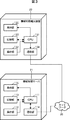
- the power control server 11 includes a power supply circuit 31, a low-pass filter 32, a high-pass filter 33, a reader / writer 34, a CPU 35, a recording unit 36, and a communication unit 37.
- the power supply circuit 31 supplies power (AC power) from the external power supply 30 to the power tap 12 through the low-pass filter 32.
- the low-pass filter 32 is disposed on the power line between the power supply circuit 31 and the power supply tap 12, and can supply power to the power supply tap 12 to which the electronic device 13 is connected.
- the low-pass filter 32 blocks a high-frequency signal generated by the reader / writer 34 and transmitted via the power line.
- the high pass filter 33 passes the high frequency signal generated by the reader / writer 34 and transmits the high frequency signal to the power tap 12 through the power line.
- the high pass filter 33 cuts off power supplied via the power line.
- the reader / writer 34 communicates with the electronic device 13 through the power line according to the control of the CPU 35.
- the reader / writer 34 is originally for electromagnetically coupling with the IC chip and for transmitting / receiving a high-frequency signal to / from the IC chip. That is, the reader / writer 34 is provided for writing and reading information according to the standard of the IC chip.
- a high frequency signal (AC signal) is transmitted / received via the power line. That is, the high-frequency signal originally transmitted / received by the coil or the like in the reader / writer 34 is superimposed on the power line via the high-pass filter, and communication with the IC chip is performed via the power line.
- the CPU 35 executes the control program recorded in the recording unit 36, thereby controlling the authentication process of the electronic device 13 and the operation of each unit of the power control server 11. In addition, the CPU 35 records information obtained by communication with the electronic device 13 via the power line in the recording unit 36.
- the communication unit 37 communicates with the user terminal device 14 according to the control of the CPU 35, and supplies information obtained through communication with the user terminal device 14 to the CPU 35.
- the CPU 35 records information obtained through communication with the user terminal device 14 in the recording unit 36.
- the communication unit 37 transmits the information recorded in the recording unit 36 to the information management server 21 via the network 20 according to the control of the CPU 35.
- the power control server 11 is configured as described above.
- the power tap 12 includes a high-pass filter 51, a power measurement unit 52-1, a power measurement unit 52-2, a switch 53-1, a switch 53-2, an outlet 54-1, an outlet 54-2, an IC chip 55, and a CPU 56. Composed.
- the high-pass filter 51 passes the high-frequency signal generated by the reader / writer 34 of the power control server 11 and transmits it to the IC chip 55 through the power line.
- the high pass filter 51 cuts off the power supplied via the power line.
- the power measuring unit 52-1 measures the power supplied via the power line under the control of the CPU 56, and supplies the measurement result to the CPU 56.
- the power measurement unit 52-2 measures power in the same manner as the power measurement unit 52-1.
- the switch 53-1 is disposed on the power line between the power measuring unit 52-1 and the outlet 54-1, and performs a switching operation under the control of the CPU 56. That is, when the switch 53-1 is turned on (energized), the power from the power control server 11 is supplied to the outlet 54-1 via the power line. On the other hand, when the switch 53-1 is in an off state (a power shielding state), power is not supplied to the outlet 54-1.
- the switch 53-2 controls the power supplied to the outlet 54-2 by performing a switching operation in the same manner as the switch 53-1.
- a plug 71 of the electronic device 13 is connected to the outlet 54-1 or the outlet 54-2, and power is supplied to the electronic device 13 through a power line.
- the outlet 54-1 and the outlet 54-2 transmit the high-frequency signal generated by the reader / writer 34 to the electronic device 13 connected via the power line.
- the IC chip 55 rectifies the voltage obtained from the high-frequency signal superimposed on the power line, acquires a command corresponding to the high-frequency signal transmitted from the reader / writer 34 with the power obtained as a result, and supplies the command to the CPU 56.
- the CPU 56 performs processing according to the command supplied from the IC chip 55. Specifically, the CPU 56 controls the switch 53-1 to be in an on state or an off state in accordance with a command from the IC chip 55. Further, the CPU 56 acquires the measurement result of the power measured by the power measurement unit 52-1 in response to the command from the IC chip 55 and returns the measurement result to the reader / writer 34.
- the power measurement unit 52 when it is not necessary to distinguish between the power measurement unit 52-1 and the power measurement unit 52-2, the power measurement unit 52 is referred to as the power measurement unit 52, and it is not necessary to distinguish between the switch 53-1 and the switch 53-2. In this case, it is referred to as a switch 53, and when there is no need to distinguish between the outlet 54-1 and the outlet 54-2, it is referred to as an outlet 54.
- the power tap 12 is configured as described above.
- the electronic device 13 includes a plug 71, a low-pass filter 72, a power supply circuit 73, a high-pass filter 74, an IC chip 75, and a microcomputer 76.
- the plug 71 is connected to the outlet 54 of the power strip 12.
- the low-pass filter 72 is disposed on a power line between the plug 71 and the power supply circuit 73, and can supply power to the power supply circuit 73 through the power line.
- the power supply circuit 73 converts the power supplied via the power line, for example, from AC power to DC power and supplies it to each part of the electronic device 13. Thereby, each part of the electronic device 13 becomes operable.
- the high-pass filter 74 is disposed on a power line between the plug 71 and the IC chip 75, and enables high-frequency signals to be exchanged between the IC chip 75 and the reader / writer 34 of the power control server 11 via the power line. .
- the high pass filter 74 prevents power supplied via the power line from being input to the IC chip 75.
- the IC chip 75 rectifies the voltage obtained from the high-frequency signal superimposed on the power line, and performs processing according to the command corresponding to the high-frequency signal transmitted from the reader / writer 34 with the resulting power.
- the IC chip 75 performs load modulation on the processing result and transmits it to the reader / writer 34 via the power line.
- the IC chip 75 is a storage element and includes a memory 75A, and stores information and processing results transmitted from the reader / writer 34, and supplies the information to the microcomputer 76. be able to.
- the IC chip 75 can be configured by an electronic tag such as an IC tag based on various standards. For example, not only standards such as FeliCa, NFC (Near Field Communication), RFID (Radio Frequency Identity), Mifare (both are trademarks), but also an electronic tag having a unique configuration not based on these standards can be prepared.
- the IC chip 75 preferably has a function of reading and outputting at least information stored therein by a high-frequency signal, and a function of storing the supplied information. Moreover, either a passive type or an active type may be used.
- the microcomputer 76 performs various processes based on information supplied from the IC chip 75. Further, the microcomputer 76 can write various types of information into the memory 75A of the IC chip 75.
- the electronic device 13 is configured as described above.
- the user terminal device 14 includes a CPU 91, an operation unit 92, a recording unit 93, a communication unit 94, and a display unit 95.
- the CPU 91 controls the operation of each unit of the user terminal device 14 by executing the control program recorded in the recording unit 93.
- the operation unit 92 supplies an operation signal corresponding to a user operation to the CPU 91.
- the CPU 91 performs processing according to the operation signal supplied from the operation unit 92.
- the communication unit 94 communicates with the information management server 21 via the power control server 11 or the network 20 in accordance with the control of the CPU 91, and supplies information obtained by the communication to the CPU 91.
- the CPU 91 records information supplied from the communication unit 94 in the recording unit 93 or displays it on the display unit 95.
- the user terminal device 14 is configured as described above.
- the information management server 21 includes a CPU 111, an operation unit 112, a recording unit 113, a communication unit 114, and a display unit 115.
- the CPU 111 controls the operation of each unit of the information management server 21 by executing the control program recorded in the recording unit 113.
- the operation unit 112 supplies an operation signal corresponding to a user operation to the CPU 111.
- the CPU 111 performs processing according to the operation signal supplied from the operation unit 112.
- the communication unit 114 communicates with the user terminal device 14 or the information use terminal device 22 via the network 20 according to the control of the CPU 111, and supplies information obtained by the communication to the CPU 111.
- the CPU 111 records information supplied from the communication unit 114 in the recording unit 113 or displays it on the display unit 115.
- the information management server 21 is configured as described above.
- the information using terminal device 22 includes a CPU 131, an operation unit 132, a recording unit 133, a communication unit 134, and a display unit 135.
- the CPU 131 controls the operation of each unit of the information using terminal device 22 by executing the control program recorded in the recording unit 133.
- the operation unit 132 supplies an operation signal corresponding to a user operation to the CPU 131.
- the CPU 131 performs processing according to the operation signal supplied from the operation unit 132.
- the communication unit 134 communicates with the information management server 21 via the network 20 under the control of the CPU 131 and supplies information obtained by the communication to the CPU 131.
- the CPU 131 records information supplied from the communication unit 134 in the recording unit 133 or displays the information on the display unit 135.
- the information using terminal device 22 is configured as described above.
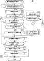
- step S11 When the plug 71 of the electronic device 13 is connected to the outlet 54 of the power strip 12 (“Yes” in step S11), the electronic device connection process is started, and the device authentication process is performed in step S12.
- the power control server 11 performs an authentication process for the connected electronic device 13. The details of the device authentication process will be described later with reference to the flowchart of FIG.
- step S13 If the connected electronic device 13 is authenticated as a valid electronic device by the device authentication process (“Yes” in step S13), information about the electronic device (hereinafter referred to as device information) is acquired from the electronic device 13. The process proceeds to step S14.
- device information information about the electronic device
- step S ⁇ b> 22 the power control server 11 performs connection confirmation as to whether or not to permit connection of an electronic device that has not been authenticated to the user terminal device 14. If the user operating the user terminal device 14 permits the connection of the unauthenticated electronic device (“Yes” in step S23), the process proceeds to step S14. If the connection of the electronic device not authenticated by the user is not permitted (“No” in step S23), the subsequent processing is not performed, and the electronic device connection processing in FIG. 4 ends.
- step S14 the power control server 11 determines whether or not the electronic device 13 authenticated as valid is a newly connected electronic device. If it is determined in step S14 that the electronic device is newly connected, it is necessary to perform user registration, and the process proceeds to step S15.
- step S15 the power control server 11 determines whether or not information related to the user (hereinafter referred to as user information) is recorded. If it is determined in step S15 that user information is not recorded, the process proceeds to step S16. In step S16, an initial user registration process is performed.
- user information is input by the user terminal device 14, and the input user information is recorded in the power control server 11. Further, the user information is transmitted to the information management server 21 via the network 20 by the power control server 11 together with the device information.
- the information management server 21 receives user information and device information, and performs user registration processing based on the information.
- user registration processing for example, registration of a warranty card, user registration of a manufacturer or a store, and the like are performed. Details of the initial user registration process will be described later with reference to the flowchart of FIG.
- step S15 if it is determined in step S15 that user information has already been recorded, the process proceeds to step S17.
- step S17 the second and subsequent user registration processes are performed.
- the power control server 11 acquires user information recorded by the first user registration process, and transmits it to the information management server 21 via the network 20 together with the device information.
- the information management server 21 receives user information and device information, and performs user registration processing based on the information. Details of the second and subsequent user registration processes will be described later with reference to the flowchart of FIG.
- step S16 or S17 When the process of step S16 or S17 is performed and the user registration of the newly connected electronic device is completed, the process proceeds to step S18. If it is determined in step S14 that the electronic device is not a newly connected electronic device, the process has already been registered, so steps S15 to S17 are skipped, and the process proceeds to step S18.
- step S18 usage history accumulation processing is performed.
- the power control server 11 acquires information on the usage status of the connected electronic device 13 (hereinafter referred to as usage history information), and the information is stored in the information management server 21 via the network 20 together with the device information. Sent.
- the information management server 21 receives usage history information and device information, and accumulates usage history information for each electronic device 13. Details of the usage history accumulation process will be described later with reference to the flowchart of FIG.
- This use history storage process is continued until it is determined that the use of the electronic device 13 is finished, for example, the electronic device 13 is removed from the power tap 12 (“No” in step S19).
- step S19 it is determined whether to use information stored by the information management server 21 such as user information, device information, or usage history information. If it is determined in step S20 that information is to be used, the process proceeds to step S21.
- step S21 information use processing is performed.
- the information management server 21 provides information such as user information, device information, or use history information in response to a request from the user terminal device 14 or the information use terminal device 22. Details of the information use process will be described later with reference to the flowcharts of FIGS.
- step S20 when the information use process of step S20 is completed or when it is determined not to use the information (“No” of step S20), the electronic device connection process of FIG. 4 is ended.
- a procedure such as registration of a warranty after purchasing the electronic device 13 is triggered by one operation of inserting the plug 71 of the electronic device 13 into the outlet 54. Further, since the use history information of the electronic device 13 is accumulated while the plug 71 of the electronic device 13 is inserted into the outlet 54, the information can be shared with other terminal devices.
- step S11 in FIG. 4 device authentication processing is started.
- step S31 the CPU 35 generates a device information read command. Specifically, device information including at least identification information for identifying itself is stored in the memory 75A of the IC chip 75 of the electronic device 13, and a command for reading this is generated.
- step S32 the reader / writer 34 modulates a high frequency signal as a high frequency signal in response to the command. Specifically, the reader / writer 34 modulates the amplitude of a carrier wave having a frequency of 13.56 MHz as a high-frequency signal in accordance with the command generated in step S31. In step S33, the reader / writer 34 outputs a high-frequency signal via the power line.
- the high-frequency signal output from the power control server 11 is transmitted to the electronic device 13 connected to the power tap 12 through the power line.
- the high frequency signal is superimposed on the alternating current.
- the IC chip 75 receives the high frequency signal transmitted through the power line (step S51).
- step S52 the IC chip 75 executes a device information read command using the power obtained from the received high-frequency signal, and reads the device information stored in the memory 75A (step S53).
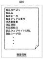
- FIG. 6 is a diagram showing an example of device information stored in the memory 75A of the IC chip 75. As shown in FIG. 6
- the memory 75A as device information, for example, product category, product name, manufacturer, manufacturing serial number, distributor, warranty period, use start date, and product website URL (Uniform Resource) Locator) is written before the product is sold.
- device information for example, product category, product name, manufacturer, manufacturing serial number, distributor, warranty period, use start date, and product website URL (Uniform Resource) Locator
- product website URL Uniform Resource
- step S54 the IC chip 75 performs load modulation in accordance with the read device information.
- the reflected wave signal generated by the load modulation of the high frequency signal is received by the power control server 11 via the power line.
- the reader / writer 34 demodulates the reflected wave signal generated by the load modulation (step S34). Thereby, the device information is read from the electronic device 13.
- step S35 the CPU 35 checks whether or not the identification information (for example, the manufacturing serial number in FIG. 6) included in the read device information matches the registered identification information. That is, identification information for identifying an electronic device that is permitted to supply power is registered in advance in the power control server 11, and it is determined whether the registered identification information matches the read identification information. Is done.
- the identification information for example, the manufacturing serial number in FIG. 6
- step S36 the CPU 35 determines whether or not the connected electronic device 13 is a valid electronic device based on the collation result in step S35.
- step S36 If it is determined in step S36 that the electronic device is a legitimate electronic device, the process proceeds to step S37.
- step S37 the CPU 35 performs processing as a valid electronic device. For example, as a legitimate electronic device process, a process of recording the read device information in the recording unit 36 is performed. Thereby, for example, the device information of FIG. 6 is recorded in the recording unit 36.
- step S36 determines whether the electronic device is an illegal electronic device. If it is determined in step S36 that the electronic device is an illegal electronic device, the process proceeds to step S38.
- step S38 the CPU 35 performs processing as an inappropriate electronic device. For example, as an illegal electronic device process, an error process is performed when authentication fails.
- step S39 the CPU 35 generates a command corresponding to the collation result.
- step S40 the reader / writer 34 modulates the high-frequency signal in response to the command corresponding to the collation result, and outputs it through the power line (step S41).
- the high-frequency signal output from the power control server 11 is transmitted to the power tap 12 through the power line.
- step S61 the IC chip 55 receives the high-frequency signal transmitted through the power line (step S61).
- step S62 the CPU 56 controls the switch 53 by executing a command corresponding to the collation result obtained from the received high frequency signal.
- the CPU 56 when a legitimate electronic device is connected, the CPU 56 performs control to turn on the switch 53 based on a command corresponding to the collation result. Thereby, electric power is supplied to the connected electronic device 13.
- the CPU 56 when an unauthorized electronic device is connected, the CPU 56 performs control to turn off the switch 53 based on a command corresponding to the collation result, and power is not supplied to the electronic device 13. Become.
- step S62 When the process of step S62 is completed, the device authentication process of FIG. 5 is terminated. And a process returns to step S12 of FIG. 4, and the process after step S13 is performed.
- the authentication process based on the authentication information read from the electronic device 13 is performed, and power is supplied only when the device is authenticated as a legitimate electronic device. .
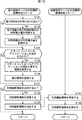
- FIG. 1 As described above, when a legitimate electronic device is connected and the electronic device is newly connected, when the user information is not recorded in the recording unit 36 of the power control server 11, FIG. The first user registration process is started.
- the CPU 35 reads and acquires the device information of the electronic device 13 recorded in the recording unit 36 (step S71).
- the communication unit 37 transmits the acquired device information to the information management server 21 via the network 20 under the control of the CPU 35.
- the information management server 21 receives the device information transmitted from the power control server 11 by the communication unit 114 (step S81). In step S ⁇ b> 82, the CPU 111 records the received device information in the recording unit 113. In addition, it becomes possible to manage apparatus information for every information management server 21 because the information management server 21 transmits the identification information for identifying itself with apparatus information.
- step S83 the CPU 111 acquires a remote control application corresponding to the identification information included in the device information.
- the information using business operator stores, in advance, a remote control application for controlling the electronic device as information on the electronic device with which the business operator is involved in the recording unit 113 of the information management server 21 provided by the information providing business operator. You can register. Thereby, the CPU 111 acquires the remote control application corresponding to the connected electronic device 13 from the recording unit 113 based on the identification information such as the manufacturing serial number and the product name.
- step S84 the communication unit 114 transmits the acquired remote control application to the power control server 11 via the network 20.
- the remote control application When the remote control application is transmitted from the information management server 21, the remote control application is received by the power control server 11 and transferred to the user terminal device 14. In the power control server 11, the received remote control application may be recorded in the recording unit 36.
- the remote control application transferred from the power control server 11 is received by the communication unit 94 (step S91).
- the CPU 91 records the received remote control application in the recording unit 93.
- step S93 the CPU 91 executes the remote control application recorded in the recording unit 93 and accepts input of user information.
- user information for example, information related to user registration such as information necessary for registering a warranty card of the electronic device 13 is input by operating the operation unit 92 by the user.
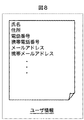
- FIG. 8 is a diagram showing an example of user information to be input.
- a name, an address, a telephone number, a mobile phone number, a mail address, and a mobile mail address are input.
- step S ⁇ b> 94 the communication unit 94 transmits the input user information to the power control server 11.
- the user information is transmitted from the user terminal device 14, the user information is received by the communication unit 37 in the power control server 11 (step S73).
- step S74 the CPU 35 records the received user information in the recording unit 36 in association with the device information.
- the device information of FIG. 6 and the user information of FIG. 8 are recorded in the recording unit 36 in association with each other.
- step S75 the communication unit 37 transmits user information to the information management server 21 via the network 20.
- the device information may be transmitted together with the user information.
- the information management server 21 receives the user information by the communication unit 114 (step S85).
- step S86 the CPU 111 performs a user registration process based on the received user information. For example, as the user registration processing, device information corresponding to the user information is read from the recording unit 113, and processing for registering a warranty card of the electronic device 13 identified by the identification information included in the device information is performed.
- step S86 When the process in step S86 is completed, the initial user registration process in FIG. 7 is terminated. And a process returns to step S16 of FIG. 4, and the process after step S18 is performed.
- the user terminal device 14 receives the remote control application of the connected electronic device 13 and executes the remote control application, so that the input user information is power. Recorded in the control server 11. Then, the user information is transmitted to the information management server 21 together with the device information from the power control server 11, and the user registration related to the electronic device 13 identified by the identification information included in the device information based on the received user information. Processing is performed.
- step S101 and S102 device information is acquired in the power control server 11 and transmitted to the information management server 21 as in steps S71 and S72 of FIG.
- the information management server 21 records the received device information and transmits a remote control application corresponding to the identification information.
- steps S121 and S122 as in steps S91 and S92 of FIG. 7, the user terminal device 14 receives and records the remote control application.
- the user information is recorded in the recording unit 36 of the power control server 11 by the first user registration process (step S74 in FIG. 7), so steps S93 and S94 in FIG. Processing corresponding to is not performed.
- the CPU 35 acquires the user information recorded by the initial user registration process (step S103) and transmits it to the information management server 21 via the network 20 (step S104).
- steps S115 and S116 user information is received in the same manner as steps S85 and S86 in FIG. 7, and for example, a process of registering a warranty card of the electronic device 13 is performed based on the user information.
- step S116 When the process in step S116 is completed, the second and subsequent user registration processes in FIG. 9 are terminated. And a process returns to step S17 of FIG. 4, and the process after step S18 is performed.
- the user terminal device 14 receives the remote control application of the connected electronic device 13, but the user information is not input, and the power control server 11 The user information recorded in is read. Then, the user information is transmitted to the information management server 21 together with the device information from the power control server 11, and the user registration related to the electronic device 13 identified by the identification information included in the device information based on the received user information. Processing is performed.
- the information management server 21 may record the user information transmitted from the power control server 11 in the recording unit 113 in association with the device information. Accordingly, the information management server 21 can perform the user registration process by reading the user information from the recording unit 113 without receiving the user information from the power control server 11 in the second and subsequent user registration processes. It becomes. Furthermore, the information management server 21 can also provide user information recorded in the recording unit 113 in response to a request from the user terminal device 14 or the information use terminal device 22.
- the usage history is immediately after the user registration process is completed, or when the user device is not a newly connected electronic device 13.
- the accumulation process is started.
- the CPU 35 determines whether or not to query the electronic device 13 about the power usage status (step S131). If it is determined in step S131 that the power usage status is inquired, the process proceeds to step S132.
- step S132 the CPU 35 acquires the power usage time and power usage amount of the electronic device 13, and records the information in the recording unit 36 (step S133).
- the CPU 35 controls the reader / writer 34 to communicate with the IC chip 55 via the power line, thereby acquiring the power amount measured by the power measuring unit 52, and calculating the power usage time and the power usage amount.
- so-called intermittent polling is performed by the reader / writer 34, and the power usage time and the power usage amount are sequentially recorded in the recording unit 36.
- the power usage time and the power consumption can be sequentially recorded, for example, in the information usage process, it is possible to present, for example, a graph showing the power consumption in time series to the user terminal device 14. Become.
- step S131 determines whether the power usage status is not inquired. If it is determined in step S131 that the power usage status is not inquired, steps S132 and S133 are skipped, and the process proceeds to step S134.
- step S134 the CPU 35 determines whether or not the remote control application has been operated. If it is determined in step S134 that the remote control application has been operated, the process proceeds to step S135.
- step S135 the CPU 35 acquires information related to the operation of the remote control application, and records the operation information in the recording unit 36 (step S136).
- the CPU 35 controls the communication unit 37 and communicates with the user terminal device 14 to acquire operation information.
- step S134 determines whether the remote control application is operated. If it is determined in step S134 that the remote control application is not operated, steps S135 and S136 are skipped, and the process proceeds to step S137.
- the recording unit 36 has a usage history such as a power usage time, a power usage amount, and an application operation history for each electronic device 13, as shown in FIG. Information is recorded.
- step S ⁇ b> 137 the CPU 35 determines whether or not to transmit the usage history information recorded in the recording unit 36 to the information management server 21.
- step S137 for example, when it is determined to transmit the usage history information based on an instruction from the user or information set in advance, the process proceeds to step S138.
- step S138 the CPU 35 reads and acquires the usage history information recorded in the recording unit 36.
- step S139 the communication unit 37 transmits the acquired usage history information to the information management server 21 via the network 20 together with the device information of the electronic device 13 from which the usage history information has been acquired, according to the control of the CPU 35. .
- step S141 When the usage history information and the device information are transmitted from the power control server 11, the usage history information and the device information are received by the communication unit 114 in the information management server 21 (step S141).
- step S142 the CPU 111 records the received usage history information and device information in the recording unit 113 in association with each other. Thereby, in the information management server 21, usage history information is accumulated for each electronic device 13.
- step S137 determines whether the usage history information is transmitted. If it is determined in step S137 that the usage history information is not transmitted, steps S138 and S139 are skipped, and the usage history storage processing in FIG. And a process returns to step S18 of FIG. 4, and the subsequent processes are performed. That is, until it is determined that the use of the electronic device 13 is finished (“Yes” in step S19 in FIG. 4), the use history storage process in step S18 is repeated, and the use history information is stored in the information management server 21. .
- the usage history information of the electronic device 13 is acquired by the power control server 11 and transmitted to the information management server 21. As a result, the usage history information is accumulated in the information management server 21.
- the communication unit 94 transmits a request for browsing the device information of the target electronic device 13 to the information management server 21 via the network 20 in accordance with the control of the CPU 91 (step S151).
- the information management server 21 receives the browsing request transmitted from the user terminal device 14 by the communication unit 114 (step S161).
- step S162 the CPU 111 reads out and acquires the device information of the target electronic device 13 from the recording unit 113 based on the received browsing request.
- the target electronic device 13 is specified by, for example, identification information included in the device information.
- step S163 the communication unit 114 transmits the acquired device information to the user terminal device 14 via the network 20.
- the user terminal device 14 receives the device information transmitted from the information management server 21 by the communication unit 94 (step S152).
- the CPU 91 causes the display unit 95 to display the received device information.
- the user can check the device information of the electronic device 13 owned by the user.
- the browsing of the device information has been described as an example, but other than that, for example, the user information stored in the information management server 21 or information on the warranty can be browsed. Is possible.
- the electronic device 13 breaks down, the information on the warranty card of the electronic device 13 can be confirmed, and the support information of the manufacturer and the dealer can be accessed to quickly deal with it.
- the user can quickly obtain the operation manual when necessary.
- step S153 When the process in step S153 is completed, the information use process performed by the user terminal device 14 in FIG. 12 is terminated. And a process returns to step S21 of FIG. 4, and subsequent processes are performed.
- the information management server 21 provides information such as device information in response to a request from the user terminal device 14. Thereby, in the user terminal device 14, information, such as apparatus information, can be displayed and a user can be confirmed.
- the power control server 11 similarly receives a request from the user terminal device 14. In response to this, the recorded device information and user information can be provided.
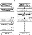
- the communication unit 134 transmits a request to view the use history information of the target electronic device 13 to the information management server 21 via the network 20 according to the control of the CPU 131 (step S171).
- the information management server 21 receives the browsing request transmitted from the information utilization terminal device 22 by the communication unit 114 (step S181).
- step S182 the CPU 111 reads and acquires the usage history information of the target electronic device 13 from the recording unit 113 based on the received browsing request.
- the target electronic device 13 is specified by, for example, identification information included in the device information.
- step S183 the communication unit 114 transmits the acquired use history information to the information use terminal device 22 via the network 20.
- the information usage terminal device 22 receives the usage history information transmitted from the information management server 21 by the communication unit 134 (step S172).
- step S173 the CPU 91 analyzes the received usage history information and causes the display unit 95 to display the analysis result (step S174).
- the analysis processing for example, based on the power usage time, the power usage amount, the application operation history, etc., the analysis processing for grasping in detail the usage status of the electronic device 13 in which the information usage company is involved is performed. Is called.
- the information service provider grasps or predicts the failure or depreciation of the electronic device 13 and notifies the user, or provides the user with sales of consumables and alternative new products. It becomes possible to do.
- step S174 When the process of step S174 is completed, the information use process performed by the information use terminal device 22 of FIG. 13 is finished. And a process returns to step S21 of FIG. 4, and subsequent processes are performed.
- the information management server 21 provides the use history information according to the request from the information use terminal device 22. Then, by analyzing the use history information, information useful for the information use company can be obtained.
- the usage history information of the electronic device 13 is collected, for example, a distribution company such as a manufacturer or a dealer, after a user purchases a product and performs user registration, It can be obtained indirectly from the information management server 21 provided by the information provider.
- a manufacturer or a distributor may install a dedicated server and collect usage history information directly via the network 20. Thereby, a manufacturer or the like can acquire information on when, where and how a consumer uses a product manufactured by the manufacturer. Then, using this information, for example, it is possible to carry out advertisements or the like according to the assumed lifetime of the product to individual users.
- the user can browse the information related to the warranty by operating the user terminal device 14 and connecting to the information management server 21. Searching for contact information or searching for contact information is eliminated.
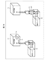
- the electronic device 13 includes the IC chip 75 and the example in which the identification information is stored in the IC chip 75 has been described.
- the identification information may be stored in the IC chip 201 by providing the IC chip 201 in the power plug adapter 15 connected to the power tap 12.
- the power control server 11 reads the identification information stored in the IC chip 201 of the power plug adapter 15 and performs authentication processing. Therefore, even the electronic device 13 that does not hold the identification information is authenticated.
- the information management server 21 stores information transmitted from the power control server 11 and provides the information use terminal device 22 and the like.
- the information management server 21 may be controlled by controlling the power control server 11 in accordance with an instruction from the information use terminal device 22 or the user terminal device 14.
- an employee of an electric power company can change the set temperature of the air conditioner under his / her jurisdiction by operating the information use terminal device 22 and connecting to the information management server 21, or unnecessary and urgent It is also possible to cut off power to electronic devices belonging to the category.
- the user who is away can control the electronic device 13 in the user's home by operating the user terminal device 14 and connecting to the information management server 21.
- a system represents the whole apparatus comprised by a some apparatus.
- the present technology can be configured as follows.
- a power supply that outputs power via a power line;
- a communication unit that reads out device information including at least identification information for identifying the electronic device by outputting a high-frequency signal via the power line and communicating with the electronic device from which power is output;
- a control unit for acquiring user information regarding a user who uses the electronic device;
- a power supply control device comprising: a transmission unit that transmits the acquired user information together with the read device information to an information management device that manages the device information.
- a recording unit for recording the user information The control unit acquires the user information input by a user when the user information is not recorded in the recording unit, and is recorded when the user information is recorded in the recording unit
- the power supply control device according to [1], which acquires user information.
- the control unit performs authentication processing of the electronic device based on the identification information included in the read device information, and outputs to the electronic device via the power line according to a result of the authentication processing
- the power supply control device according to [1] or [2], wherein the power supply is controlled.
- the communication unit obtains usage history information related to the usage status of the electronic device by outputting a high-frequency signal via the power line and performing communication.
- the power transmission control device according to any one of [1] to [3], wherein the transmission unit transmits the acquired usage history information to the information management device together with the device information.
- the electronic device is provided with a storage element that outputs the stored device information to the power supply control device via the power line by load-modulating a high-frequency signal input via the power line.
- the power supply control device according to any one of [1] to [5].
- the power supply control device Output power via the power line, Reading out device information including at least identification information for identifying the electronic device by communicating with the electronic device from which power is output by outputting a high-frequency signal via the power line, Obtaining user information relating to a user using the electronic device;
- a control method including the step of transmitting the acquired user information together with the read device information to an information management device that manages the device information.
- the power supply control device includes: A power supply that outputs power via a power line; A communication unit that reads out device information including at least identification information for identifying the electronic device by communicating with the electronic device from which power is output by outputting a high-frequency signal via the power line; A control unit for acquiring user information regarding a user who uses the electronic device; A transmission unit that transmits the acquired user information together with the read device information to the information management device;
- the information management device includes: A receiving unit that receives the user information and the device information transmitted from the power supply control device; A power supply control system comprising: a processing unit that performs user registration processing related to the electronic device identified by the identification information included in the device information based on the received user information.
- the information management device includes: A recording unit for recording the received device information; The power supply control system according to [8], wherein the processing unit performs a process of providing the recorded device information in response to a request from the terminal device.
- the communication unit obtains usage history information related to the usage status of the electronic device by outputting a high-frequency signal via the power line and performing communication.
- the transmission unit transmits the acquired usage history information together with the device information to the information management device,
- the receiving unit receives the usage history information and the device information transmitted from the power supply control device,
- the power supply control system according to [9], wherein the recording unit records the received usage history information and the device information in association with each other.
- the power supply control system according to [10], wherein the communication unit acquires a power usage time and a power usage amount of the electronic device as the usage history information.
- the power supply control system according to [10] or [11], wherein the processing unit performs a process of providing the recorded usage history information in response to a request from the terminal device.
- the electronic device includes a storage element that outputs the stored device information to the power supply control device via the power line by load-modulating a high-frequency signal input via the power line. [8] Thru
Landscapes
- Engineering & Computer Science (AREA)
- Power Engineering (AREA)
- Computer Networks & Wireless Communication (AREA)
- Signal Processing (AREA)
- Management, Administration, Business Operations System, And Electronic Commerce (AREA)
- Power Sources (AREA)
- Cable Transmission Systems, Equalization Of Radio And Reduction Of Echo (AREA)
- Selective Calling Equipment (AREA)
Priority Applications (3)
| Application Number | Priority Date | Filing Date | Title |
|---|---|---|---|
| US14/113,735 US9461708B2 (en) | 2011-05-13 | 2012-05-01 | Power supply control device, method of controlling the same, and power supply control system |
| CN201280022144.6A CN103518380B (zh) | 2011-05-13 | 2012-05-01 | 电力供给控制装置及其控制方法、以及电力供给控制系统 |
| EP12784952.9A EP2709373A4 (en) | 2011-05-13 | 2012-05-01 | POWER SUPPLY CONTROL DEVICE AND CONTROL METHOD THEREFOR AND POWER SUPPLY CONTROL SYSTEM |
Applications Claiming Priority (2)
| Application Number | Priority Date | Filing Date | Title |
|---|---|---|---|
| JP2011108120A JP5895363B2 (ja) | 2011-05-13 | 2011-05-13 | 電力供給制御装置及びその制御方法、並びに電力供給制御システム |
| JP2011-108120 | 2011-05-13 |
Publications (1)
| Publication Number | Publication Date |
|---|---|
| WO2012157445A1 true WO2012157445A1 (ja) | 2012-11-22 |
Family
ID=47176780
Family Applications (1)
| Application Number | Title | Priority Date | Filing Date |
|---|---|---|---|
| PCT/JP2012/061527 Ceased WO2012157445A1 (ja) | 2011-05-13 | 2012-05-01 | 電力供給制御装置及びその制御方法、並びに電力供給制御システム |
Country Status (5)
| Country | Link |
|---|---|
| US (1) | US9461708B2 (enExample) |
| EP (1) | EP2709373A4 (enExample) |
| JP (1) | JP5895363B2 (enExample) |
| CN (1) | CN103518380B (enExample) |
| WO (1) | WO2012157445A1 (enExample) |
Families Citing this family (4)
| Publication number | Priority date | Publication date | Assignee | Title |
|---|---|---|---|---|
| CN104285384B (zh) * | 2012-05-25 | 2016-09-07 | 株式会社吉川Rf半导体 | 电力线通信系统 |
| WO2015011867A1 (ja) * | 2013-07-26 | 2015-01-29 | パナソニック インテレクチュアル プロパティ コーポレーション オブ アメリカ | 情報管理方法 |
| KR101435626B1 (ko) * | 2013-08-19 | 2014-08-28 | 주식회사 인코어드 테크놀로지스 | 에너지 사용 기기 및 에너지 정보 수집 장치 |
| JP2015201144A (ja) * | 2014-04-10 | 2015-11-12 | パナソニックIpマネジメント株式会社 | 情報取得装置、情報取得方法 |
Citations (6)
| Publication number | Priority date | Publication date | Assignee | Title |
|---|---|---|---|---|
| JP2001028093A (ja) * | 1999-07-15 | 2001-01-30 | Shikoku Electric Power Co Inc | 電力量計 |
| JP2004030147A (ja) | 2002-06-25 | 2004-01-29 | Toppan Printing Co Ltd | 製品、製品のパッケージ、製品の保証書作成登録方法および保証書作成登録システム |
| JP2004104863A (ja) * | 2002-09-05 | 2004-04-02 | Funai Electric Co Ltd | 電力供給制御システム |
| JP2005026740A (ja) * | 2003-06-30 | 2005-01-27 | Matsushita Electric Ind Co Ltd | 機器制御インタフェース構築方法 |
| JP2007257328A (ja) * | 2006-03-23 | 2007-10-04 | Nec Corp | 製品管理システム及び製品管理方法 |
| JP2008153852A (ja) * | 2006-12-15 | 2008-07-03 | Mitsubishi Electric Corp | 電力線搬送システム、及びその電源装置、電気錠装置、サーバ |
Family Cites Families (13)
| Publication number | Priority date | Publication date | Assignee | Title |
|---|---|---|---|---|
| BR0017145A (pt) * | 2000-03-08 | 2002-12-10 | Ascom Powerline Comm Ag | Acoplamento de uma cabeça de rede a uma rede de alimentação de baixa tensão |
| JP2002014749A (ja) * | 2000-06-30 | 2002-01-18 | Mitsubishi Electric Corp | 電源システム |
| ES2550821T3 (es) * | 2002-01-24 | 2015-11-12 | Panasonic Corporation | Método de y sistema para comunicaciones de portadora por línea eléctrica |
| JP4215519B2 (ja) * | 2003-01-10 | 2009-01-28 | パナソニック電工株式会社 | 電気機器管理支援システム、電気機器管理支援用センターサーバ |
| US7236765B2 (en) * | 2003-07-24 | 2007-06-26 | Hunt Technologies, Inc. | Data communication over power lines |
| JP2006180384A (ja) * | 2004-12-24 | 2006-07-06 | Toshiba Corp | 通信ユニットおよびその通信方法 |
| JP4859636B2 (ja) * | 2006-11-20 | 2012-01-25 | 中国電力株式会社 | 電力使用量管理システム、電力使用量管理方法 |
| JP2008257347A (ja) * | 2007-04-02 | 2008-10-23 | Tokyo Electric Power Co Inc:The | 情報管理システム、及び情報管理方法 |
| JP2009158109A (ja) * | 2007-12-25 | 2009-07-16 | Panasonic Electric Works Co Ltd | コンセント及びコンセントプラグ |
| US8278784B2 (en) * | 2008-07-28 | 2012-10-02 | Qualcomm Incorporated | Wireless power transmission for electronic devices |
| US7786419B2 (en) * | 2008-09-30 | 2010-08-31 | The Invention Science Fund I, Llc | Beam power with beam redirection |
| US9545851B2 (en) * | 2010-02-25 | 2017-01-17 | Panasonic Automotive Systems Company Of America, Division Of Panasonic Corporation Of North America | Vehicle bi-directional power inverter system and method |
| US20110289336A1 (en) * | 2010-05-24 | 2011-11-24 | Aboundi, Inc. | Data transfer enabled uninterruptable power system |
-
2011
- 2011-05-13 JP JP2011108120A patent/JP5895363B2/ja not_active Expired - Fee Related
-
2012
- 2012-05-01 US US14/113,735 patent/US9461708B2/en active Active
- 2012-05-01 EP EP12784952.9A patent/EP2709373A4/en not_active Withdrawn
- 2012-05-01 CN CN201280022144.6A patent/CN103518380B/zh not_active Expired - Fee Related
- 2012-05-01 WO PCT/JP2012/061527 patent/WO2012157445A1/ja not_active Ceased
Patent Citations (6)
| Publication number | Priority date | Publication date | Assignee | Title |
|---|---|---|---|---|
| JP2001028093A (ja) * | 1999-07-15 | 2001-01-30 | Shikoku Electric Power Co Inc | 電力量計 |
| JP2004030147A (ja) | 2002-06-25 | 2004-01-29 | Toppan Printing Co Ltd | 製品、製品のパッケージ、製品の保証書作成登録方法および保証書作成登録システム |
| JP2004104863A (ja) * | 2002-09-05 | 2004-04-02 | Funai Electric Co Ltd | 電力供給制御システム |
| JP2005026740A (ja) * | 2003-06-30 | 2005-01-27 | Matsushita Electric Ind Co Ltd | 機器制御インタフェース構築方法 |
| JP2007257328A (ja) * | 2006-03-23 | 2007-10-04 | Nec Corp | 製品管理システム及び製品管理方法 |
| JP2008153852A (ja) * | 2006-12-15 | 2008-07-03 | Mitsubishi Electric Corp | 電力線搬送システム、及びその電源装置、電気錠装置、サーバ |
Non-Patent Citations (1)
| Title |
|---|
| See also references of EP2709373A4 * |
Also Published As
| Publication number | Publication date |
|---|---|
| CN103518380A (zh) | 2014-01-15 |
| EP2709373A4 (en) | 2014-12-17 |
| EP2709373A1 (en) | 2014-03-19 |
| JP2012239111A (ja) | 2012-12-06 |
| US20140044200A1 (en) | 2014-02-13 |
| JP5895363B2 (ja) | 2016-03-30 |
| US9461708B2 (en) | 2016-10-04 |
| CN103518380B (zh) | 2017-07-28 |
Similar Documents
| Publication | Publication Date | Title |
|---|---|---|
| US8995957B2 (en) | Communication apparatus, communication method and communication system | |
| US8855563B2 (en) | Communication apparatus and communication method | |
| US10909597B2 (en) | Application sales management server system and method | |
| US8461725B1 (en) | Identification of powered devices for energy saving | |
| US20160132840A1 (en) | Methods and systems for evaluating and recycling electronic devices | |
| CN109286652B (zh) | 应用销售管理服务器系统以及边缘服务器 | |
| CN102750162A (zh) | 将已安装在旧移动终端上的应用安装到新移动终端的方法 | |
| US10805335B2 (en) | Application security management system and edge server | |
| JP5895363B2 (ja) | 電力供給制御装置及びその制御方法、並びに電力供給制御システム | |
| JP2009075644A (ja) | 製品ライフサイクル情報管理システム及び方法 | |
| KR20120025863A (ko) | 이미지 코드를 이용한 제품 이력 관리 시스템 및 휴대형 장치에서 이미지 코드를 이용한 제품 이력 관리 방법 | |
| JP7306910B2 (ja) | アプリケーション販売管理サーバシステム、アプリケーション販売管理システム、管理制御装置及び配信制御装置 | |
| CN109640297B (zh) | 无卡交互系统及模拟卡设备 | |
| WO2019168783A1 (en) | System and method for securely transferring ownership of wireless tags | |
| JP2014119807A (ja) | 電子マネー決済装置および電子決済システム | |
| KR20160011279A (ko) | 주문 관리 시스템 | |
| KR20100035456A (ko) | Rfid를 이용하여 진품 인증 서비스를 제공하기 위한 방법 및 시스템 | |
| US20170345020A1 (en) | Authentication of retailers and distributors | |
| US20190028457A1 (en) | Application sales management server system | |
| WO2019168782A1 (en) | System and method for managing wireless tag functionality | |
| KR20150102810A (ko) | 통합 인증 장치 및 그 동작 방법 | |
| US20080147520A1 (en) | Method and apparatus for providing electronic inventory service | |
| WO2022153439A1 (ja) | 情報提供システム、サーバ装置、情報提供方法、および情報提供プログラム | |
| JP2005228066A (ja) | 電子タグシステム、無線タグ、リーダ装置及びプログラム | |
| TWI708160B (zh) | 一種用於售後服務之保證服務管理系統及其方法 |
Legal Events
| Date | Code | Title | Description |
|---|---|---|---|
| 121 | Ep: the epo has been informed by wipo that ep was designated in this application |
Ref document number: 12784952 Country of ref document: EP Kind code of ref document: A1 |
|
| WWE | Wipo information: entry into national phase |
Ref document number: 2012784952 Country of ref document: EP |
|
| WWE | Wipo information: entry into national phase |
Ref document number: 14113735 Country of ref document: US |
|
| NENP | Non-entry into the national phase |
Ref country code: DE |