WO2012157206A1 - 自動分析装置 - Google Patents
自動分析装置 Download PDFInfo
- Publication number
- WO2012157206A1 WO2012157206A1 PCT/JP2012/003018 JP2012003018W WO2012157206A1 WO 2012157206 A1 WO2012157206 A1 WO 2012157206A1 JP 2012003018 W JP2012003018 W JP 2012003018W WO 2012157206 A1 WO2012157206 A1 WO 2012157206A1
- Authority
- WO
- WIPO (PCT)
- Prior art keywords
- light
- light receiving
- process data
- reaction process
- automatic analyzer
- Prior art date
- Legal status (The legal status is an assumption and is not a legal conclusion. Google has not performed a legal analysis and makes no representation as to the accuracy of the status listed.)
- Ceased
Links
Images


Classifications
-
- G—PHYSICS
- G01—MEASURING; TESTING
- G01N—INVESTIGATING OR ANALYSING MATERIALS BY DETERMINING THEIR CHEMICAL OR PHYSICAL PROPERTIES
- G01N35/00—Automatic analysis not limited to methods or materials provided for in any single one of groups G01N1/00 - G01N33/00; Handling materials therefor
- G01N35/02—Automatic analysis not limited to methods or materials provided for in any single one of groups G01N1/00 - G01N33/00; Handling materials therefor using a plurality of sample containers moved by a conveyor system past one or more treatment or analysis stations
- G01N35/025—Automatic analysis not limited to methods or materials provided for in any single one of groups G01N1/00 - G01N33/00; Handling materials therefor using a plurality of sample containers moved by a conveyor system past one or more treatment or analysis stations having a carousel or turntable for reaction cells or cuvettes
-
- G—PHYSICS
- G01—MEASURING; TESTING
- G01N—INVESTIGATING OR ANALYSING MATERIALS BY DETERMINING THEIR CHEMICAL OR PHYSICAL PROPERTIES
- G01N21/00—Investigating or analysing materials by the use of optical means, i.e. using sub-millimetre waves, infrared, visible or ultraviolet light
- G01N21/17—Systems in which incident light is modified in accordance with the properties of the material investigated
- G01N21/47—Scattering, i.e. diffuse reflection
- G01N21/49—Scattering, i.e. diffuse reflection within a body or fluid
- G01N21/51—Scattering, i.e. diffuse reflection within a body or fluid inside a container, e.g. in an ampoule
-
- G—PHYSICS
- G01—MEASURING; TESTING
- G01N—INVESTIGATING OR ANALYSING MATERIALS BY DETERMINING THEIR CHEMICAL OR PHYSICAL PROPERTIES
- G01N21/00—Investigating or analysing materials by the use of optical means, i.e. using sub-millimetre waves, infrared, visible or ultraviolet light
- G01N21/75—Systems in which material is subjected to a chemical reaction, the progress or the result of the reaction being investigated
- G01N21/77—Systems in which material is subjected to a chemical reaction, the progress or the result of the reaction being investigated by observing the effect on a chemical indicator
- G01N21/82—Systems in which material is subjected to a chemical reaction, the progress or the result of the reaction being investigated by observing the effect on a chemical indicator producing a precipitate or turbidity
-
- G—PHYSICS
- G01—MEASURING; TESTING
- G01N—INVESTIGATING OR ANALYSING MATERIALS BY DETERMINING THEIR CHEMICAL OR PHYSICAL PROPERTIES
- G01N21/00—Investigating or analysing materials by the use of optical means, i.e. using sub-millimetre waves, infrared, visible or ultraviolet light
- G01N21/17—Systems in which incident light is modified in accordance with the properties of the material investigated
- G01N21/47—Scattering, i.e. diffuse reflection
- G01N2021/4704—Angular selective
- G01N2021/4711—Multiangle measurement
-
- G—PHYSICS
- G01—MEASURING; TESTING
- G01N—INVESTIGATING OR ANALYSING MATERIALS BY DETERMINING THEIR CHEMICAL OR PHYSICAL PROPERTIES
- G01N35/00—Automatic analysis not limited to methods or materials provided for in any single one of groups G01N1/00 - G01N33/00; Handling materials therefor
- G01N35/02—Automatic analysis not limited to methods or materials provided for in any single one of groups G01N1/00 - G01N33/00; Handling materials therefor using a plurality of sample containers moved by a conveyor system past one or more treatment or analysis stations
- G01N35/04—Details of the conveyor system
- G01N2035/0439—Rotary sample carriers, i.e. carousels
- G01N2035/0453—Multiple carousels working in parallel
Definitions
- the present invention relates to an analyzer for measuring the concentration of a measurement substance contained in a sample, for example, an automatic analyzer for quantifying the concentration of a measurement substance contained in blood or urine.
- a color reaction between a substrate and an enzyme There are mainly two types of reactions measured by an automatic analyzer: a color reaction between a substrate and an enzyme, and an immune agglutination reaction between an antigen and an antibody.
- the analysis using the former reaction is called biochemical analysis, and the test items include LDH (lactate dehydrogenase), ALP (alkaline phosphatase), and AST (aspartate oxoglutarate aminoton rafenase).
- Analysis using the latter reaction is called immunoassay, and test items include CRP (C-reactive protein), IgG (immunoglobulin), and RF (rheumatoid factor).
- Latex immunoassay In latex immunoassay, light is irradiated to an aggregate formed by aggregating latex particles with a measurement substance, and the amount of transmitted light transmitted without being scattered is measured. Since the size of the aggregate after a certain period of time increases as the concentration of the measurement substance increases, the concentration of the measurement substance can be quantified from the amount of light measured as the reaction process data.
- Patent Document 2 is configured to enable measurement in a low concentration region, a technique for expanding the dynamic range has not been disclosed so far.
- the time series data of the amount of scattered light is measured as reaction process data, and in the automatic analyzer that quantifies the concentration of the measurement substance from the change in the amount of light, from among the reaction process data measured by a plurality of light receivers at different angles.
- An automatic analyzer having a function of selecting reaction process data used for quantification is provided. By using this function, data can be selected from reaction process data measured with multiple different angle receivers depending on the concentration of the measurement target, high sensitivity priority that prioritizes sensitivity, or dynamic range priority. Display quantitative results.
- a cell that contains a reaction liquid in which a sample and a reagent are mixed, a cell disk that holds the cell on the circumference, repeats rotation and stop, and a cell Data processing for processing the reaction process data of the reaction liquid measured by the light source that irradiates the light, multiple light receivers that receive scattered light from the reaction liquid contained in the cell at different light receiving angles, respectively And an output unit that outputs a processing result by the data processing unit, the data processing unit includes information on the light reception angles of the plurality of light receivers, and from among reaction process data measured by the plurality of light receivers The reaction process data used to output the reaction liquid quantitative value is selected based on the information on the light receiving angles of the multiple light receivers, and the reaction liquid quantitative value calculated from the selected reaction process data is output. Characterized in that it.
- the receiver As the multiple receiving angles for measuring scattered light, the receiver is placed at 20 ° and 30 ° positions with respect to the light emitted from the light source, and the user specifies whether to give priority to dynamic range or high sensitivity. A case will be described in which the quantitative result is displayed based on the reaction process data measured at the light receiving angle according to the above.
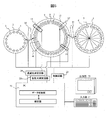
- FIG. 5 is a schematic diagram showing an example of the overall configuration of the automatic analyzer according to the present invention.
- This automatic analyzer is equipped with a scattered light measurement circuit.
- the automatic analyzer mainly includes three types of disks, a sample disk 3, a reagent disk 6 and a cell disk 9, a dispensing mechanism for moving samples and reagents between these disks, a control circuit 23 for controlling these, and a transmitted light measurement.
- Circuit 24, scattered light measurement circuit 25 analysis unit in data processing unit 26 such as a PC (computer) for processing measured data, data storage unit for storing control data, measurement data, data used for analysis, and analysis result data
- the input unit 27 and the output unit 28 are interfaces for inputting / outputting data to / from the data storage unit.
- a plurality of sample cups 2 containing samples 1 are arranged on the circumference of the sample disk 3.
- a plurality of reagent bottles 5 containing the reagents 4 are arranged on the reagent disk 6.
- a plurality of cells 8 are prepared on the circumference in which the sample 1 and the reagent 4 are mixed to form a reaction solution 7.
- the sample dispensing mechanism 10 moves the sample 1 from the sample cup 2 to the cell 8 by a certain amount.
- the reagent dispensing mechanism 11 moves the reagent 4 from the reagent bottle 5 to the cell 8 by a certain amount.
- the stirring unit 12 stirs and mixes the sample 1 and the reagent 4 in the cell 8.
- the cleaning unit 14 discharges the reaction solution 7 from the cell 8 after the analysis and cleans it.
- the next sample 1 is again dispensed from the sample dispensing mechanism 10 into the washed cell 8, and a new reagent 4 is dispensed from the reagent dispensing mechanism 11 and used for another reaction.
- the cell 8 is immersed in a constant temperature fluid 15 in a constant temperature bath whose temperature and flow rate are controlled, and the cell 8 and the reaction liquid 7 in the cell 8 are moved while being maintained at a constant temperature. Water is used as the constant temperature fluid 15, and the constant temperature fluid temperature is adjusted to 37 ⁇ 0.1 ° C. by the control circuit.
- a transmitted light measuring unit 13 and a scattered light measuring unit 16 are provided on a part of the circumference of the cell disk.
- the transmitted light measuring unit 13 may be configured to irradiate light from a halogen lamp light source to the cell 8, for example, and to split the transmitted light with a diffraction grating and then receive the light with a photodiode array.
- the wavelengths received are, for example, 340 nm, 405 nm, 450 nm, 480 nm, 505 nm, 546 nm, 570 nm, 600 nm, 660 nm, 700 nm, 750 nm, and 800 nm.
- the transmitted light amount data incident on these light receivers is sent to the data storage unit in the PC through the transmitted light measurement circuit.
- the scattered light measurement unit 16 is shown in FIG.
- the light source for example, an LED light source or the like can be used. Irradiated light 18 from the LED light source unit 17 shown here is irradiated to the moving cell 8, and the transmitted light 19 is transmitted by the transmitted light receiver 20 in the scattered light measuring unit. Receive light.
- the LED light source unit 17 for example, 700 nm can be used as the irradiation light wavelength.
- an LED is used as a light source, but a laser, a xenon lamp, or a halogen lamp may be used.
- Scattered light 21a and 21b in directions away from the optical axis by 20 ° and 30 ° in air are measured by scattered light receivers 22a and 22b, respectively.
- This scattered light receiver is disposed in a plane substantially perpendicular to the cell moving direction due to the rotation of the cell disk.
- a reference position of the angle the central portion of the length of light passing through the cell is set as the starting point.
- light receivers having different scattering angles may be provided.
- photodiodes are arranged as light receivers at respective angles
- a configuration may be adopted in which a single linear array holding a large number of light receivers is arranged to receive scattered light at multiple angles. Thereby, the choice of a light reception angle can be expanded.
- an optical system such as a fiber or a lens may be disposed, and the light may be guided to a scattered light receiver disposed at another position.
- Quantitative determination of a certain measurement substance in sample 1 is performed according to the following procedure. First, a certain amount of sample 1 in the sample cup 2 is dispensed into the cell 8 by the sample dispensing mechanism 10. Next, a predetermined amount of the reagent 4 in the reagent bottle 5 is dispensed into the cell 8 by the reagent dispensing mechanism 11. At the time of dispensing, the sample disk 3, the reagent disk 6 and the cell disk 9 are rotationally driven by the respective drive units under the control of the control circuit, and the sample cup 2, the reagent bottle 5 and the cell 8 are driven by the timing of the dispensing mechanism. Move to match.
- the sample 1 and the reagent 4 in the cell 8 are stirred by the stirring unit 12 to obtain a reaction solution 7.
- the transmitted light and scattered light from the reaction solution 7 are measured every time the cell disk 9 rotates and pass through the measurement positions of the transmitted light measurement unit 13 and the scattered light measurement unit 16, and the transmitted light measurement circuit and the scattered light measurement are performed.
- the reaction process data is sequentially stored in the data storage unit through the circuit. After measuring for a certain time, for example, about 10 minutes, the inside of the cell 8 is cleaned by the cleaning mechanism 14 and the next inspection item is analyzed. Meanwhile, if necessary, another reagent 4 is added into the cell 8 by the reagent dispensing mechanism 11 and dispensed, stirred by the stirring unit 12, and further measured for a certain time.
- reaction process data of the reaction solution 7 having a constant time interval is stored in the data storage unit.
- the analysis unit obtains the change in the amount of light due to the reaction for a certain period of time, and the quantitative result is calculated based on the calibration curve data stored in the data storage unit in advance. Displayed from the output unit. Data necessary for control and analysis of each unit is input from the input unit to the data storage unit. Data, results, and alarms in various storage units are output on the display or the like by the output unit.
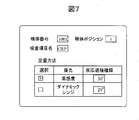
- FIG. 7 shows an example of the pre-measurement user setting screen in the first embodiment.
- the user designates the inspection item name for the sample in the sample disc designated by the specimen number and specimen position.
- the user selects either high sensitivity priority or dynamic range priority as a quantitative method in advance.
- the light reception angle of the reaction process data used at the time of quantification is selected.
- quantification is performed using reaction process data with a light reception angle of 30 ° as a priority for high sensitivity
- quantification is performed using reaction process data with a light reception angle of 20 ° smaller than 30 ° when priority is given to the dynamic range.
- An example of setting is as follows. Then, based on the user's high sensitivity priority selection, the setting is made so that a quantitative result is obtained using reaction process data at a light receiving angle of 30 °.
- the light receiving angle specified as the reaction process data used for quantification may be input by the user based on the parameters recommended in advance by the reagent manufacturer for each reagent.
- the light receiving angle for obtaining the reaction process data used for quantification is shown here by the user, but it may be automatically set in advance on the apparatus side.
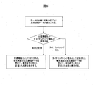
- FIG. 8 shows a flow until the quantitative result after measurement in Example 1 is displayed.
- reaction process data for each light reception angle of the data storage unit is collected and stored in the data storage unit.
- priority is given to high sensitivity priority or dynamic range priority.
- the reaction process data at the set light reception angle of 20 ° is used, and the result is quantified using the calibration data of the specified light reception angle stored in the data storage unit. indicate.
- Fig. 1 shows the amount of scattered light emitted when a single particle of polystyrene (refractive index: 1.59) in water is irradiated with light of wavelength 600-800 nm. The diameter dependency is shown for each light receiving angle.
- the amount of scattered light from the reaction solution can be easily estimated from the amount of scattered light of a single particle.
- the light receiving angle is an angle formed by the optical axis of the irradiation light and the light receiving optical axis, and is 20 °, 25 °, 30 °, and 35 ° apart from the irradiation optical axis in the air.
- the angular resolution was 2.5 °.
- the latex particles contained in the reagent of the automatic analyzer are considered to be 0.1 ⁇ m to 0.4 ⁇ m.
- the higher the concentration of the measurement substance contained in the sample the larger the aggregate (scatterer) contained in the reaction solution after a certain period of time, and the aggregate size is 0.8. It is thought that it becomes larger than ⁇ m. Therefore, it can be said that the light receiving angle at which a change in particle diameter of 0.8 ⁇ m or more can be measured is a light receiving angle having a wide measuring range up to a high concentration region.
- the amount of scattered light at a light receiving angle of 35 ° is small when the particle size is 0.8 ⁇ m or more, but the amount of scattered light is small in the 20 ° direction, but the amount of scattered light increases to 0.8 ⁇ m or more, at least to 1.2 ⁇ m. It can be seen that the amount of scattered light increases even when the particle diameter increases as the light receiving angle increases, and the measurement range tends to be wide up to the high concentration region. In particular, it can be seen that 20 ° and 25 ° angles are more advantageous than 30 ° and 35 ° light-receiving angles when measuring agglomeration reactions with a particle size of 0.8 ⁇ m or more. As described above, by using the reaction process data measured at a smaller light receiving angle for quantification, measurement with a wide dynamic range becomes possible.
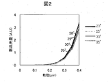
- the sensitivity in the low concentration region is compared for each light receiving angle.
- the particle size of the aggregate is considered to be almost the same as the particle size of the latex particles of the reagent. It is assumed that the particle size of the reagent is 0.1 ⁇ m and the aggregate is about 0.4 ⁇ m.
- Fig. 2 compares the particle size dependence of the amount of scattered light with a particle size of 0.1 to 0.4 ⁇ m for each angle. From FIG. 2, it can be seen that there is no significant difference in the amount of scattered light from a particle size of 0.1 ⁇ m to 0.4 ⁇ m even when the light receiving angle is changed at an angle of 20 ° to 35 °. That is, it can be seen that the change in the amount of light (signal) with respect to the change in particle size at a low concentration is almost the same at any angle.
- Fig. 4 suggests that the S / N ratio is larger in the 35 ° direction than in the 20 ° direction.
- a relatively large angle, such as 30 ° or 35 °, is more advantageous as the S / N ratio for the low-concentration region, but the light-receiving angle for the high-concentration region is also considered from FIG. It can be seen that measurement at a small angle such as 20 ° or 25 °, which can measure a large particle size change, is advantageous.
- a light receiver is placed at 20 ° and 30 ° positions with respect to the light emitted from the light source, and the result calculated as the change in the amount of light over a period of time from the reaction process data is the threshold value.
- the dynamic range is expanded by automatically selecting the light reception angle of the reaction process data used for calculating the quantitative value when reaching the measurement range defined by the lower limit and the threshold upper limit will be described.
- the basic conditions are the same as in Example 1, but the flow until the user setting screen before measurement and the quantitative result after measurement are displayed is different.
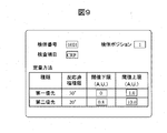
- FIG. 9 shows an example of a user setting screen before measurement in the second embodiment.
- the user designates the inspection item name for the sample in the sample disc designated by the specimen number and specimen position.
- the user sets the light receiving angles of the first priority and the second priority in advance for the scattered light receiver used for quantification.
- quantification is basically performed at the angle specified by the first priority, but at the light reception angle specified by the first priority, the result of the reaction process data is a value outside the measurement range defined by the threshold lower limit and threshold upper limit.
- the quantitative value is calculated at the second light receiving angle which is the next light receiving angle.
- the light receiving angle as these reaction process types may be input by the user based on parameters recommended in advance by the reagent manufacturer for each reagent. Alternatively, it may be automatically set in advance on the apparatus side.
- the light receiving angle with the first priority is 30 °
- the light receiving angle with the second priority is 20 °
- the first priority light receiving angle is specified to be larger than the second priority light receiving angle.
- the light receiving angle with the first priority may be 20 °
- the light receiving angle with the second priority may be 30 °.
- the user may automatically switch when the amount of scattered light reaches the threshold value or more in the reaction process data simply by designating whether the priority is high sensitivity or dynamic range.
- the light reception angle used for quantification is displayed at the same time when the quantitation value is displayed. As a result, the user can easily recognize the light receiving angle used for the quantitative value.
- the upper and lower threshold values for each angle are entered.
- the threshold is set based on the amount of scattered light
- the lower limit at 30 ° is 0, 1.0 is input as the upper limit
- the lower limit at 20 ° is 0.8
- 10.0 is input as the upper limit.
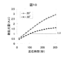
- FIG. 10 shows reaction process data of CRP 18 mg / dL measured using a CRP reagent at 20 ° and 30 ° light receiving angles. At 30 °, which gives priority to high sensitivity, the amount of scattered light (A.U.) is linear up to about 1.0, but the response curve becomes dull beyond that.
- the upper limit of the threshold is set to 1.0 in the 30 ° direction, and when the amount of scattered light reaches more than that, it is determined to switch to the second-priority light receiving angle as a smaller angle.
- the range in which the second-priority light receiving angle could be quantified was measured in advance, and the lower limit threshold was set to 0.8 and the upper limit threshold was set to 10.0.
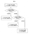
- FIG. 11 shows a flow until displaying the quantitative result after measurement in the second embodiment.
- Reaction data corresponding to each light receiver from the scattered light measurement unit is stored in the data storage unit. Then, it is confirmed whether the result of the reaction process data of the first light receiving angle (change in the amount of light over a certain period of time) is within the measurement range specified by the upper limit or the lower limit of the threshold value or is outside the range.
- the result of the reaction process data of the first light receiving angle when it is within the measurement range, it is quantified from the reaction process data of the first priority light receiving angle, and the result is displayed. If it is outside the measurement range, check if the reaction process data of the second priority light receiving angle is within the measurement range specified by the upper or lower threshold.
- reaction process data of the second priority light receiving angle is quantified and the result is displayed. If it is outside the measurement range, the result of quantification from the reaction process data of the second-priority light receiving angle and an alarm indicating a threshold value or more are simultaneously displayed.
- the basic conditions are the same as in Example 2, but the flow until the user's setting screen before measurement and the quantitative result after measurement are displayed is different.
- FIG. 12 shows an example of a user setting screen before measurement in the third embodiment. Basically the same as in the second embodiment, but a quantitative alarm value for checking whether or not to display an alarm can be set.
- Each quantitative value calculated from the reaction process data at the light reception angle specified on the setting screen may be compared, and an alarm may be displayed if the difference between the quantitative values exceeds the quantitative alarm value. Further, the quantitative alarm value is compared with the difference between the quantitative values in this embodiment, but may be a percentage (%) of how much the quantitative value is deviated.
- An example of a screen for displaying the quantitative results after measurement in Example 3 is shown in FIG.
- the quantitative result using the reaction process data at a light receiving angle of 30 ° is 0.5 mg / dL
- the quantitative result using the reaction process data at a light receiving angle of 20 ° is 0.8 mg / dL
- the difference between these quantitative values is 0.1 mg / dL.
- 0.5 mg / dL which is the quantitative value obtained from the reaction process data with the light receiving angle of 30 °, which is the first priority, is displayed as the quantitative value.
- the light receiving angle is specified one by one in accordance with the purpose.
- a light receiver having a plurality of light receiving angles can be selected. May be.
- the reaction process data measured by the light receiver having the light receiving angle that does not exceed the threshold value is obtained. It may be used for quantification.
- the present invention is applied to latex immunoassay, but may be immunoassay that does not use latex as a sensitizer.
Landscapes
- Chemical & Material Sciences (AREA)
- Physics & Mathematics (AREA)
- Immunology (AREA)
- Pathology (AREA)
- Analytical Chemistry (AREA)
- Biochemistry (AREA)
- General Health & Medical Sciences (AREA)
- General Physics & Mathematics (AREA)
- Health & Medical Sciences (AREA)
- Life Sciences & Earth Sciences (AREA)
- Chemical Kinetics & Catalysis (AREA)
- Engineering & Computer Science (AREA)
- Plasma & Fusion (AREA)
- Investigating Or Analysing Materials By The Use Of Chemical Reactions (AREA)
- Automatic Analysis And Handling Materials Therefor (AREA)
- Investigating Or Analysing Materials By Optical Means (AREA)
Priority Applications (3)
| Application Number | Priority Date | Filing Date | Title |
|---|---|---|---|
| CN201280022967.9A CN103547912B (zh) | 2011-05-13 | 2012-05-09 | 自动分析装置 |
| EP12784970.1A EP2708873B1 (en) | 2011-05-13 | 2012-05-09 | Automatic analysis device |
| US14/116,177 US9645160B2 (en) | 2011-05-13 | 2012-05-09 | Automatic analysis device |
Applications Claiming Priority (2)
| Application Number | Priority Date | Filing Date | Title |
|---|---|---|---|
| JP2011107837A JP5822534B2 (ja) | 2011-05-13 | 2011-05-13 | 自動分析装置 |
| JP2011-107837 | 2011-05-13 |
Publications (1)
| Publication Number | Publication Date |
|---|---|
| WO2012157206A1 true WO2012157206A1 (ja) | 2012-11-22 |
Family
ID=47176558
Family Applications (1)
| Application Number | Title | Priority Date | Filing Date |
|---|---|---|---|
| PCT/JP2012/003018 Ceased WO2012157206A1 (ja) | 2011-05-13 | 2012-05-09 | 自動分析装置 |
Country Status (5)
| Country | Link |
|---|---|
| US (1) | US9645160B2 (enExample) |
| EP (1) | EP2708873B1 (enExample) |
| JP (1) | JP5822534B2 (enExample) |
| CN (1) | CN103547912B (enExample) |
| WO (1) | WO2012157206A1 (enExample) |
Cited By (2)
| Publication number | Priority date | Publication date | Assignee | Title |
|---|---|---|---|---|
| WO2014013823A1 (ja) * | 2012-07-20 | 2014-01-23 | 株式会社日立ハイテクノロジーズ | 自動分析装置及び自動分析方法 |
| WO2021199178A1 (ja) * | 2020-03-30 | 2021-10-07 | デンカ生研株式会社 | ラテックス凝集法による目的物質の測定方法、およびその試薬 |
Families Citing this family (4)
| Publication number | Priority date | Publication date | Assignee | Title |
|---|---|---|---|---|
| JP6138564B2 (ja) * | 2013-04-18 | 2017-05-31 | 株式会社日立ハイテクノロジーズ | 自動分析装置 |
| JPWO2014192963A1 (ja) | 2013-05-31 | 2017-02-23 | 積水メディカル株式会社 | 免疫凝集測定法 |
| JP6730196B2 (ja) * | 2014-05-21 | 2020-07-29 | ソシエテ・デ・プロデュイ・ネスレ・エス・アー | 個人向けの栄養素含有量を有する栄養組成物を製造するためのシステム、方法、及び装置 |
| US10976333B2 (en) * | 2016-07-19 | 2021-04-13 | Hitachi High-Tech Corporation | Automatic analysis device and automatic analysis method |
Citations (4)
| Publication number | Priority date | Publication date | Assignee | Title |
|---|---|---|---|---|
| JPS58172537A (ja) * | 1982-04-04 | 1983-10-11 | Wako Pure Chem Ind Ltd | 光散乱測定装置 |
| US4451433A (en) | 1980-11-10 | 1984-05-29 | Hitachi, Ltd. | Automatic chemical analyzer |
| JP2001141654A (ja) | 1999-10-08 | 2001-05-25 | Dade Behring Marburg Gmbh | 分光光度・比濁検出ユニット |
| WO2011004781A1 (ja) * | 2009-07-10 | 2011-01-13 | 株式会社日立ハイテクノロジーズ | 自動分析装置 |
Family Cites Families (28)
| Publication number | Priority date | Publication date | Assignee | Title |
|---|---|---|---|---|
| JPS5925460B2 (ja) * | 1978-05-19 | 1984-06-18 | 株式会社日立製作所 | ネフェロメトリック・イムノアッセイ法及び装置 |
| US4766083A (en) * | 1982-04-04 | 1988-08-23 | Wako Pure Chemical Industries, Ltd. | Method for the photometric determination of biological agglutination |
| JPH0359123U (enExample) * | 1989-10-06 | 1991-06-11 | ||
| JP3059123U (ja) * | 1998-11-16 | 1999-07-02 | 日機装株式会社 | 粒度分布測定装置 |
| US6798508B2 (en) * | 2002-08-23 | 2004-09-28 | Coulter International Corp. | Fiber optic apparatus for detecting light scatter to differentiate blood cells and the like |
| GB0307756D0 (en) * | 2003-04-03 | 2003-05-07 | Suisse Electronique Microtech | Measuring the concentration and motility of light scattering particles |
| US7239386B2 (en) * | 2004-08-17 | 2007-07-03 | The Regents Of The University Of California | Compact imaging spectrometer utilizing immersed gratings |
| CN103941027B (zh) * | 2005-03-29 | 2016-09-07 | 希森美康株式会社 | 标本分析方法及标本分析装置 |
| WO2006103920A1 (ja) * | 2005-03-29 | 2006-10-05 | Sysmex Corporation | 癌・異型細胞および凝集粒子を弁別する方法および細胞分析装置 |
| US20120120385A1 (en) * | 2006-06-27 | 2012-05-17 | Jian-Ping Jiang | Pathogen detection by simultaneous size/fluorescence measurement |
| JP2008064594A (ja) * | 2006-09-07 | 2008-03-21 | Yokogawa Electric Corp | 濁度計 |
| MX2009005630A (es) * | 2006-11-29 | 2009-08-07 | Celsius S A Lab | Metodo para analizar datos de imagenes relacionados con ensayos de aglutinacion. |
| JP2008216054A (ja) * | 2007-03-05 | 2008-09-18 | Hitachi High-Technologies Corp | 被検査物の検査装置及び被検査物の検査方法 |
| US7808641B2 (en) * | 2007-04-13 | 2010-10-05 | C Technologies Inc. | Interactive variable pathlength device |
| WO2009017721A2 (en) * | 2007-07-28 | 2009-02-05 | Buglab Llc | Particle sensor with wide linear range |
| EP2522982B1 (en) * | 2007-08-15 | 2015-09-16 | Malvern Instruments Limited | Broad-Range Spectrometer |
| DE102008018592A1 (de) * | 2008-04-11 | 2009-10-15 | Endress + Hauser Conducta Gesellschaft für Mess- und Regeltechnik mbH + Co. KG | Verfahren und Vorrichtung zur Trübungsmessung |
| JP2009281930A (ja) * | 2008-05-23 | 2009-12-03 | Yokogawa Electric Corp | 粒子濃度測定装置 |
| CA2728833C (en) * | 2008-07-04 | 2018-02-27 | Canadian Blood Services | Dynamic light scattering for in vitro testing of bodily fluids |
| JP5319696B2 (ja) * | 2008-11-17 | 2013-10-16 | 株式会社日立ハイテクノロジーズ | 自動分析装置 |
| US8506799B2 (en) * | 2009-09-09 | 2013-08-13 | ClearCorp | Suspended particle characterization system for a water processing facility |
| CN102640004B (zh) * | 2009-12-04 | 2015-04-15 | 株式会社日立高新技术 | 血液凝固分析装置 |
| DE102010002420A1 (de) * | 2010-02-26 | 2011-09-01 | Robert Bosch Gmbh | Verfahren und Vorrichtung zur Bestimmung der Qualität der Messergebnisse eines Streulichtmessgerätes |
| CN103026232B (zh) * | 2010-03-01 | 2015-02-04 | 匡特里克斯公司 | 扩大用于检测分子或颗粒的测定法中的动态范围的方法和系统 |
| JP5296015B2 (ja) * | 2010-06-22 | 2013-09-25 | 株式会社日立ハイテクノロジーズ | 自動分析装置 |
| US8681215B2 (en) * | 2011-04-29 | 2014-03-25 | ProteinSimple | Method and particle analyzer for determining a broad particle size distribution |
| US20120287435A1 (en) * | 2011-05-12 | 2012-11-15 | Jmar Llc | Automatic dilution for multiple angle light scattering (mals) instrument |
| US9168523B2 (en) * | 2011-05-18 | 2015-10-27 | 3M Innovative Properties Company | Systems and methods for detecting the presence of a selected volume of material in a sample processing device |
-
2011
- 2011-05-13 JP JP2011107837A patent/JP5822534B2/ja active Active
-
2012
- 2012-05-09 CN CN201280022967.9A patent/CN103547912B/zh active Active
- 2012-05-09 EP EP12784970.1A patent/EP2708873B1/en active Active
- 2012-05-09 WO PCT/JP2012/003018 patent/WO2012157206A1/ja not_active Ceased
- 2012-05-09 US US14/116,177 patent/US9645160B2/en active Active
Patent Citations (4)
| Publication number | Priority date | Publication date | Assignee | Title |
|---|---|---|---|---|
| US4451433A (en) | 1980-11-10 | 1984-05-29 | Hitachi, Ltd. | Automatic chemical analyzer |
| JPS58172537A (ja) * | 1982-04-04 | 1983-10-11 | Wako Pure Chem Ind Ltd | 光散乱測定装置 |
| JP2001141654A (ja) | 1999-10-08 | 2001-05-25 | Dade Behring Marburg Gmbh | 分光光度・比濁検出ユニット |
| WO2011004781A1 (ja) * | 2009-07-10 | 2011-01-13 | 株式会社日立ハイテクノロジーズ | 自動分析装置 |
Non-Patent Citations (1)
| Title |
|---|
| C. F. BOHREN; D. R. HUFFMAN: "Absorption and Scattering of Light by Small Particles", 1983, J. WILEY & SONS |
Cited By (2)
| Publication number | Priority date | Publication date | Assignee | Title |
|---|---|---|---|---|
| WO2014013823A1 (ja) * | 2012-07-20 | 2014-01-23 | 株式会社日立ハイテクノロジーズ | 自動分析装置及び自動分析方法 |
| WO2021199178A1 (ja) * | 2020-03-30 | 2021-10-07 | デンカ生研株式会社 | ラテックス凝集法による目的物質の測定方法、およびその試薬 |
Also Published As
| Publication number | Publication date |
|---|---|
| EP2708873A1 (en) | 2014-03-19 |
| JP2012237691A (ja) | 2012-12-06 |
| US20140140890A1 (en) | 2014-05-22 |
| EP2708873B1 (en) | 2019-06-19 |
| EP2708873A4 (en) | 2014-10-08 |
| CN103547912B (zh) | 2015-11-25 |
| CN103547912A (zh) | 2014-01-29 |
| JP5822534B2 (ja) | 2015-11-24 |
| US9645160B2 (en) | 2017-05-09 |
Similar Documents
| Publication | Publication Date | Title |
|---|---|---|
| JP5948173B2 (ja) | 自動分析装置及び自動分析方法 | |
| JP5740264B2 (ja) | 自動分析装置及び分析方法 | |
| JP6013796B2 (ja) | 自動分析装置及び試料測定方法 | |
| JP6110710B2 (ja) | 分析装置及び自動分析装置 | |
| JP5822534B2 (ja) | 自動分析装置 | |
| JP6134210B2 (ja) | 自動分析装置及び自動分析方法 | |
| JP5296015B2 (ja) | 自動分析装置 | |
| JP6576843B2 (ja) | 自動分析装置及びその散乱光測定光学系評価用標準液 | |
| JP2014137319A (ja) | 自動分析装置 | |
| JP6437390B2 (ja) | 自動分析装置 | |
| JP6031552B2 (ja) | 自動分析装置及び分析方法 | |
| JP6138564B2 (ja) | 自動分析装置 | |
| JP6657016B2 (ja) | 自動分析装置 | |
| JP7691284B2 (ja) | 自動分析装置および検体分析方法 | |
| WO2016129029A1 (ja) | 自動分析装置 |
Legal Events
| Date | Code | Title | Description |
|---|---|---|---|
| 121 | Ep: the epo has been informed by wipo that ep was designated in this application |
Ref document number: 12784970 Country of ref document: EP Kind code of ref document: A1 |
|
| WWE | Wipo information: entry into national phase |
Ref document number: 2012784970 Country of ref document: EP |
|
| NENP | Non-entry into the national phase |
Ref country code: DE |
|
| WWE | Wipo information: entry into national phase |
Ref document number: 14116177 Country of ref document: US |