EP2708873B1 - Automatic analysis device - Google Patents
Automatic analysis device Download PDFInfo
- Publication number
- EP2708873B1 EP2708873B1 EP12784970.1A EP12784970A EP2708873B1 EP 2708873 B1 EP2708873 B1 EP 2708873B1 EP 12784970 A EP12784970 A EP 12784970A EP 2708873 B1 EP2708873 B1 EP 2708873B1
- Authority
- EP
- European Patent Office
- Prior art keywords
- light
- process data
- reaction process
- receiving angle
- receiving
- Prior art date
- Legal status (The legal status is an assumption and is not a legal conclusion. Google has not performed a legal analysis and makes no representation as to the accuracy of the status listed.)
- Active
Links
Images


Classifications
-
- G—PHYSICS
- G01—MEASURING; TESTING
- G01N—INVESTIGATING OR ANALYSING MATERIALS BY DETERMINING THEIR CHEMICAL OR PHYSICAL PROPERTIES
- G01N35/00—Automatic analysis not limited to methods or materials provided for in any single one of groups G01N1/00 - G01N33/00; Handling materials therefor
- G01N35/02—Automatic analysis not limited to methods or materials provided for in any single one of groups G01N1/00 - G01N33/00; Handling materials therefor using a plurality of sample containers moved by a conveyor system past one or more treatment or analysis stations
- G01N35/025—Automatic analysis not limited to methods or materials provided for in any single one of groups G01N1/00 - G01N33/00; Handling materials therefor using a plurality of sample containers moved by a conveyor system past one or more treatment or analysis stations having a carousel or turntable for reaction cells or cuvettes
-
- G—PHYSICS
- G01—MEASURING; TESTING
- G01N—INVESTIGATING OR ANALYSING MATERIALS BY DETERMINING THEIR CHEMICAL OR PHYSICAL PROPERTIES
- G01N21/00—Investigating or analysing materials by the use of optical means, i.e. using sub-millimetre waves, infrared, visible or ultraviolet light
- G01N21/17—Systems in which incident light is modified in accordance with the properties of the material investigated
- G01N21/47—Scattering, i.e. diffuse reflection
- G01N21/49—Scattering, i.e. diffuse reflection within a body or fluid
- G01N21/51—Scattering, i.e. diffuse reflection within a body or fluid inside a container, e.g. in an ampoule
-
- G—PHYSICS
- G01—MEASURING; TESTING
- G01N—INVESTIGATING OR ANALYSING MATERIALS BY DETERMINING THEIR CHEMICAL OR PHYSICAL PROPERTIES
- G01N21/00—Investigating or analysing materials by the use of optical means, i.e. using sub-millimetre waves, infrared, visible or ultraviolet light
- G01N21/75—Systems in which material is subjected to a chemical reaction, the progress or the result of the reaction being investigated
- G01N21/77—Systems in which material is subjected to a chemical reaction, the progress or the result of the reaction being investigated by observing the effect on a chemical indicator
- G01N21/82—Systems in which material is subjected to a chemical reaction, the progress or the result of the reaction being investigated by observing the effect on a chemical indicator producing a precipitate or turbidity
-
- G—PHYSICS
- G01—MEASURING; TESTING
- G01N—INVESTIGATING OR ANALYSING MATERIALS BY DETERMINING THEIR CHEMICAL OR PHYSICAL PROPERTIES
- G01N21/00—Investigating or analysing materials by the use of optical means, i.e. using sub-millimetre waves, infrared, visible or ultraviolet light
- G01N21/17—Systems in which incident light is modified in accordance with the properties of the material investigated
- G01N21/47—Scattering, i.e. diffuse reflection
- G01N2021/4704—Angular selective
- G01N2021/4711—Multiangle measurement
-
- G—PHYSICS
- G01—MEASURING; TESTING
- G01N—INVESTIGATING OR ANALYSING MATERIALS BY DETERMINING THEIR CHEMICAL OR PHYSICAL PROPERTIES
- G01N35/00—Automatic analysis not limited to methods or materials provided for in any single one of groups G01N1/00 - G01N33/00; Handling materials therefor
- G01N35/02—Automatic analysis not limited to methods or materials provided for in any single one of groups G01N1/00 - G01N33/00; Handling materials therefor using a plurality of sample containers moved by a conveyor system past one or more treatment or analysis stations
- G01N35/04—Details of the conveyor system
- G01N2035/0439—Rotary sample carriers, i.e. carousels
- G01N2035/0453—Multiple carousels working in parallel
Definitions
- the present invention relates to an analysis device, which measures the concentration of an analyte contained in a sample, for example, an automatic analysis device, which quantitatively determines the concentration of an analyte contained in blood or urine.
- An automatic analysis device which irradiates a reaction mixture obtained by mixing a sample with a reagent with a light from a light source, calculates an absorbance from a change in the amount of a transmitted light with a specific wavelength, and quantitatively determines the concentration of an analyte according to the Lambert-Beer law, has been widely used (for example, PTL 1).
- a device in such a device, in a cell disk which repeats rotation and stop, a lot of cells each retaining a reaction mixture are arranged on a circumference thereof, time sequential data on the amount of a transmitted light transmitted through the reaction mixture in the cell is measured as reaction process data at about 15 second intervals for about 10 minutes by a transmitted light measuring section disposed at a given position during the rotation of the cell disk, an absorbance is calculated from a change in light amount, and the concentration of an analyte is quantitatively determined.
- reaction for which the measurement is performed by the automatic analysis device there are mainly the following two types of reactions: a color reaction in which a substrate and an enzyme are reacted with each other, and an immune agglutination reaction in which an antigen and an antibody are reacted with each other.
- An analysis using the former reaction is called a biochemical analysis, and examples of a test item include LDH (lactate dehydrogenase), ALP (alkaline phosphatase), and AST (aspartate-oxoglutarate aminotransferase).
- An analysis using the latter reaction is called an immunoassay, and examples of a test item include CRP (C-reactive protein), IgG (immunoglobulin), and RF (rheumatoid factor) .
- CRP C-reactive protein
- IgG immunoglobulin
- RF rheumatoid factor
- an agglutinated body produced by agglutinating the latex particles by an analyte is irradiated with a light, and the amount of a transmitted light transmitted without scattering is measured.
- the size of the agglutinated body after the lapse of a predetermined time is increased as the concentration of an analyte is increased, and therefore, the concentration of the analyte can be quantitatively determined from a light amount measured as reaction process data.
- a latex immunoassay have higher sensitivity.
- a large number of reagents for use in an automatic analysis device have been developed so far, however, there are the following two types of reagents: a reagent for use in a normal analysis and a reagent compatible with a highly sensitive analysis, and a user needs to select to select a reagent depending on the intended use.
- the device in order to further increase the sensitivity of the latex immunoassay, it has been tried to measure a scattered light not to measure a transmitted light so far. For example, a system which separates a transmitted light and a scattered light from each other using a diaphragm and simultaneously measures an absorbance and a scattered light (PTL 2), etc. have been disclosed.
- WO 2011/004781 A1 describes an automatic analyzer with a light receiver at an angle of 17.7° or less from an optical axis of irradiation light, in order to ensure sufficient integration time.
- WO 2011/162113 A1 describes an automatic analysis device which suppresses the effects of noise, during concentration analysis, by calculating correlation between scattered light.
- WO2011/068049 discloses an automatic analyzer with light receivers at multiple scattering angles, wherein the the receivers are assigned a priority order, and the signal from a receiver of lower priority is used in case the one from a receiver of higher priority is not suitable for the analysis.
- WO2011/162113 and WO2011/068049 are part of the state of the art under Art. 54(3) EPC.
- the measurement of a scattered light enables detection of a change in light amount largely even in a low concentration range as compared with the measurement of a transmitted light, but has a problem that it is susceptible to noise from dust or an air bubble due to the low light amount as compared with a transmitted light.
- a constant temperature fluid is circulated around a cell for stabilizing the temperature of the reaction mixture, and therefore; dust or an air bubble is likely to be present. There was no structure capable of performing measurement with high sensitivity even under such a circumstance.
- PTL 2 discloses a structure enabling the measurement in a low concentration range, however, a technique for expanding a dynamic range has not been disclosed yet.
- the present invention provides an automatic analysis device which measures time sequential data on a scattered light amount as reaction process data, and quantitatively determines the concentration of an analyte from a change in light amount.
- the automatic analysis device has a function of selecting reaction process data to be used for quantitative determination from the reaction process data obtained by measurement using a plurality of light receivers at different angles . As a result of using this function, data is selected from the reaction process data obtained by measurement using the plurality of light receivers at different angles in accordance with the concentration of the analyte and whether the priority is given to high sensitivity in the case where sensitivity is prioritized or a dynamic range, and the result of the quantitative determination is displayed.
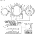
- Fig. 5 is a schematic view showing an overall structural example of an automatic analysis device according to the present invention.
- This automatic analysis device is mounted with a scattered light measuring circuit.
- the automatic analysis device mainly includes the following three types of disks: a sample disk 3, a reagent disk 6, and a cell disk 9, dispensing mechanisms which transfer a sample or a reagent between these disks, a control circuit 23 which controls these members, a transmitted light measuring circuit 24, a scattered light measuring circuit 25, an analysis section in a data processing section 26 such as a PC (computer) which processes data obtained by measurement, a data storage section which stores control data, measurement data, data to be used for an analysis, and analysis result data, and an input section 27 and an output section 28 serving as an interface which inputs or outputs data with respect to the data storage section.
- a sample disk 3 a reagent disk 6, and a cell disk 9, dispensing mechanisms which transfer a sample or a reagent between these disks
- a control circuit 23 which controls these members
- sample disk 3 a plurality of sample cups 2 in which a sample 1 is placed are arranged on a circumference thereof.
- reagent bottles 5 in which a reagent 4 is placed are arranged.
- cell disk 9 a plurality of cells 8 in which the sample 1 and the reagent 4 are mixed to form a reaction mixture 7 are arranged on a circumference thereof.
- a sample dispensing mechanism 10 transfers a given amount of the sample 1 from the sample cup 2 to the cell 8.
- a reagent dispensing mechanism 11 transfers a given amount of the reagent 4 from the reagent bottle 5 to the cell 8.
- a stirring section 12 stirs and mixes the sample 1 and the reagent 4 in the cell 8.
- a washing section 14 discharges the reaction mixture 7 from the cell 8 after completion of the analysis and washes the cell 8.
- a subsequent sample 1 is dispensed again by the sample dispensing mechanism 10, and a fresh reagent 4 is dispensed by the reagent dispensing mechanism 11, and thus, the cell 8 is used for another reaction.
- the cell 8 is immersed in a constant temperature fluid 15 in a constant temperature bath in which the temperature and the flow rate are controlled, and is moved in a state where the temperatures of the cell 8 and the reaction mixture 7 therein are maintained constant.
- the constant temperature fluid 15 water is used, and the temperature of the constant temperature fluid is regulated at 37 ⁇ 0.1°C by the control circuit.
- a transmitted light measuring section 13 and a scattered light measuring section 16 are fitted to a part of the cell disk on a circumference thereof.
- the transmitted light measuring section 13 can be configured such that the cell 8 is irradiated with a light from, for example, a halogen lamp light source, and a transmitted light is dispersed by a diffraction grating, and then, a dispersed light is received by a photodiode array.
- the wavelengths of the light to be received are 340 nm, 405 nm, 450 nm, 480 nm, 505 nm, 546 nm, 570 nm, 600 nm, 660 nm, 700 nm, 750 nm, and 800 nm.
- the data on the amount of the transmitted light entering these light receivers is sent to the data storage section in the PC through the transmitted light measuring circuit.
- a schematic view of the scattered light measuring section 16 is shown in Fig. 6 .
- the light source for example, an LED light source or the like can be used.
- the cell 8 in motion is irradiated with an irradiation light 18 from an LED light source unit 17 shown in this drawing, and a transmitted light 19 is received by a transmitted light receiver 20 in the scattered light measuring section.
- the LED light source unit 17 as the wavelength of the irradiation light, for example, 700 nm can be used.
- an LED is used, but a laser, a xenon lamp, or a halogen lamp may be used.
- Scattered lights 21a and 21b forward in the direction separated at an angle of 20° or 30° with respect to the optical axis in the air are measured by scattered light receivers 22a and 22b, respectively.
- These scattered light receivers are arranged in a plane substantially perpendicular to the moving direction of the cell by the rotation of the cell disk.
- the reference position of the angle the center of the length of a light path in the cell was defined as the origin. It is sufficient to provide as a unit which receives a scattered light from the reaction mixture, a light receiver which receives a light at a different scattering angle.
- Photodiodes are disposed as the light receivers at the respective angles, however, a configuration in which a single linear array having a plurality of light receivers therein is disposed to receive scattered lights at a plurality of angles may be adopted. According to this, the choice of the light-receiving angles can be expanded. Further, it is also possible to dispose an optical system such as a fiber or a lens in place of the receiver to guide a light to the scattered light receiver disposed at another place.
- an optical system such as a fiber or a lens
- the quantitative determination of the concentration of an analyte present in the sample 1 is performed according to the following procedure. First, a given amount of the sample 1 in the sample cup 2 is dispensed to the cell 8 by the sample dispensing mechanism 10. Subsequently, a given amount of the reagent 4 in the reagent bottle 5 is dispensed to the cell 8 by the reagent dispensing mechanism 11. When dispensing these liquids, the sample disk 3, the reagent disk 6, and the cell disk 9 are rotationally driven by the respective driving sections under the control of the control circuit to move the sample cup 2, the reagent bottle 5, and the cell 8 in accordance with the timing of the dispensing mechanisms.
- the sample 1 and the reagent 4 in the cell 8 are stirred by the stirring section 12 to form a reaction mixture 7.
- a transmitted light and a scattered light from the reaction mixture 7 are measured every time the cell 8 passes by the measurement positions by the transmitted light measuring section 13 and the scattered light measuring section 16 during the rotation of the cell disk 9, and the measurement data is stored as the reaction process data in the data storage section sequentially through the transmitted light measuring circuit and the scattered light measuring circuit.
- the inside of the cell 8 is washed by the washing mechanism 14, and an analysis is performed for the subsequent test item.
- Fig. 7 shows one example of a user setting screen before measurement according to the first embodiment.
- a user designates a test item name for the sample in the sample disk designated by the sample number and the sample position.
- the user selects whether the priority is given to high sensitivity or a dynamic range as the quantitative determination method beforehand. By doing this, the light-receiving angle of the reaction process data to be used when performing quantitative determination is selected.
- the setting is made such that quantitative determination is performed by using the reaction process data on the light-receiving angle of 30° in the case where the priority is given to high sensitivity
- quantitative determination is performed by using the reaction process data on the light-receiving angle of 20° which is smaller than 30° in the case where the priority is given to a dynamic range.
- the setting is made such that a quantitative determination result is output using the reaction process data on the light-receiving angle of 30°.
- the light-receiving angle designated for the reaction process data to be used when performing quantitative determination may be input by a user beforehand on the basis of a parameter recommended by the manufacturer of the reagent with respect to each reagent. Further, a case where a user designates and inputs the light-receiving angle for acquiring the reaction process data to be used for quantitative determination is described here, but it may be automatically set beforehand on the device side.
- Fig. 8 shows a flow of a procedure until a quantitative determination result after measurement is displayed according to the first embodiment.
- the reaction process data with respect to each light-receiving angle in the data storage section is collected and stored in the data storage section. Subsequently, it is confirmed whether the priority is given to high sensitivity or a dynamic range in the above-described user setting screen.
- the priority is given to high sensitivity, and therefore, by using the reaction process data on the light-receiving angle of 20°, which has been set, quantitative determination is performed with calibration data on the designated light-receiving angle stored in the data storage section, and the result is displayed.
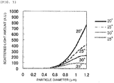
- the particle diameter dependence of the amount of a scattered light generated when a single polystyrene particle (refractive index: 1.59) present in water is irradiated with a light with a wavelength of 600 to 800 nm with respect to each light-receiving angle is shown in Fig. 1 .
- the amount of a scattered light from a reaction mixture can be easily inferred from the amount of a scattered light from a single particle.
- the light-receiving angle is an angle formed by the optical axis of an irradiation light and the optical axis of a received light, and was set to 20°, 25°, 30°, and 35° with respect to the optical axis of an irradiation light in the air. Further, the angular resolution was set to 2.5°. That is, in the case where the light-receiving angle was 20°, in fact, an average light amount of a scattered light at a light-receiving angle ranging from 17.5° to 22.5° was calculated. The calculation was performed using Mie scattering theory. The Mie scattering theory is described in, for example, the following Non Patent Literature.
- Latex particles contained in the reagent of the automatic analysis device are considered to have a size ranging from 0.1 ⁇ m to 0.4 ⁇ m.
- a latex immunoassay it is considered that as the concentration of an analyte contained in a sample is higher, that is, as the concentration range is higher, the size of an agglutinated body (a scattering body) contained in a reaction mixture after the lapse of a predetermined time is increased, and the size of the agglutinated body is increased to 0.8 ⁇ m or more.
- a light-receiving angle at which a change in particle diameter which is 0.8 ⁇ m or more can be measured is regarded as a light-receiving angle with a wide measurement range including a high concentration range.
- the increment of the scattered light amount at a light-receiving angle of 35° is small in the case where the particle diameter is 0.8 ⁇ m or more, however, the scattered light amount at a light-receiving angle of 20° is increased in the case where the particle diameter is 0.8 ⁇ m or more, up to at least 1.2 ⁇ m.
- the scattered light amount is increased as the light-receiving angle is smaller even if the particle diameter is increased, and the measurement range is wide including a high concentration range.
- the measurement at a light-receiving angle of 20° or 25° is more advantageous than the measurement at a light-receiving angle of 30° or 35°. In this manner, it becomes possible to perform measurement with an expanded dynamic range by using the reaction process data obtained by measurement at a smaller light-receiving angle for quantitative determination.
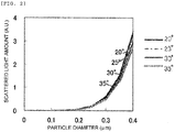
- the sensitivity in a low concentration range is compared with respect to each light-receiving angle. It is considered that in a low concentration range, the particle diameter of an agglutinated body is substantially the same as that of a latex particle of the reagent. It is assumed that the particle diameter of the reagent is 0.1 ⁇ m and the particle diameter of an agglutinated body is about 0.4 ⁇ m. In Fig. 2 , the particle diameter dependence of the scattered light amount when the particle diameter is from about 0.1 ⁇ m to 0.4 ⁇ m is compared with respect to each angle. From Fig.
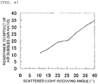
- the ratio of the signal when a scattered light is obtained for 10 9 latex particles in the case where the particle diameter of the latex particle is 0.1 ⁇ m to the noise is defined as an S/N ratio, and the angle dependence of the S/N ratio is shown in Fig. 4 .
- the S/N ratio is larger in the case where the light-receiving angle is 35° than in the case where the light-receiving angle is 20°. From this result, it is found that as the light-receiving angle for use in a low concentration range, a relatively large angle such as 30° or 35° is advantageous to the S/N ratio, however, as the light-receiving angle for use in a high concentration range, the measurement at a small angle such as 20° or 25° is advantageous since such a small angle enables the measurement of a change in particle diameter which is large also in consideration of the results shown in Fig. 1 .
- the basic condition is the same as that of the first embodiment, but a user setting screen before measurement and a flow of a procedure until a quantitative determination result after measurement is displayed are different from the first embodiment.
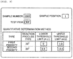
- Fig. 9 shows one example of a user setting screen before measurement according to the second embodiment of this disclosure and within the scope of the present invention.
- a user designates a test item name for the sample in the sample disk designated by the sample number and the sample position.
- the user sets the light-receiving angles of the first priority and the second priority beforehand for a scattered light receiver to be used for quantitative determination.
- the quantitative determination is basically performed at an angle designated as the first priority, however, if the result of the reaction process data at the light-receiving angle designated as the first priority shows a value outside the measurement range defined by a lower threshold limit and an upper threshold limit, a quantitative value is calculated at a second light-receiving angle, which is the subsequent light-receiving angle.
- These light-receiving angles which are types of the reaction process may be input by a user beforehand on the basis of a parameter recommended by the manufacturer of the reagent with respect to each reagent. Further, the light-receiving angle may be automatically set beforehand on the device side.
- the light-receiving angle of the first priority is set to 30° and the light-receiving angle of the second priority is set to 20°, and therefore, the light-receiving angle of the first priority is specified to be larger than the light-receiving angle of the second priority. By doing this, it becomes possible to perform a more highly sensitive measurement.
- the light-receiving angle of the first priority may be set to 20° and the light-receiving angle of the second priority may be set to 30°.
- the user does not designate these light-receiving angles, but only designates whether the priority is given to high sensitivity or a dynamic range, and when the scattered light amount in the reaction process data has reached a value exceeding the threshold, the light-receiving angle may be automatically changed. Further, in the case where the light-receiving angle is changed, when the quantitative value is displayed, the light-receiving angle used for the quantitative determination is also displayed at the same time. This enables the user to easily recognize the light-receiving angle used for obtaining the quantitative value.
- the upper and lower threshold limits for the respective angles are also input.
- the thresholds are set on the basis of the scattered light amount, and when the angle is 30°, 0 is input as the lower limit and 1.0 is input as the upper limit, and when the angle is 20°, 0.8 is input as the lower limit and 10.0 is input as the upper limit.
- Fig. 10 shows the reaction process data obtained by measurement using a CRP reagent at light-receiving angles of 20° and 30° at a CRP of 18 mg/dL.
- the scattered light amount (A.U.) shows linearity up to about 1.0, but when the scattered light amount is 1.0 or more, the reaction curve is blunted.
- the upper threshold limit at a light-receiving angle of 30° was set to 1.0, and in the case where the scattered light amount reached a value exceeding 1.0, the light-receiving angle was changed to the second priority angle set to a smaller angle, and the quantitative determination was performed. Further, also for the light-receiving angle of the second priority, a quantitatively determinable range was determined beforehand, and the lower threshold limit was set to 0.8, and the upper threshold limit was set to 10.0.
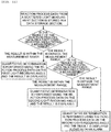
- FIG. 11 A flow of a procedure until a quantitative determination result after measurement is displayed according to the invention is shown in Fig. 11 .
- the reaction process data in accordance with each light receiver from the scattered light measuring section is stored in the data storage section. Then, it is confirmed whether the result of the reaction process data on the first light-receiving angle (a change in light amount within a predetermined time period) is within or outside a measurement range defined by an upper or lower threshold limit.
- the result is within the measurement range
- quantitative determination is performed using the reaction process data on the light-receiving angle of the first priority, and the result is displayed.
- the result is outside the measurement range, it is confirmed whether the reaction process data on the light-receiving angle of the second priority is within or outside a measurement range defined by an upper or lower threshold limit.
- quantitative determination is performed using the reaction process data on the light-receiving angle of the second priority, and the result is displayed.
- the result of the quantitative determination obtained using the reaction process data on the light-receiving angle of the second priority and an alarm which indicates that the result exceeds the threshold are displayed at the same time.
- the basic condition is the same as that of the second embodiment, but a user setting screen before measurement and a flow of a procedure until a quantitative determination result after measurement is displayed are different from the second embodiment and from the claimed invention.
- Fig. 12 shows one example of a user setting screen before measurement according to the third embodiment. It is basically the same as that of the second embodiment, but it is configured such that a quantitative alarm value to be used in checking whether an alarm is displayed or not can be set.
- the respective quantitative values calculated from the reaction process data on the light-receiving angles designated in the setting screen are compared, and when a difference between the quantitative values exceeds the quantitative alarm value, an alarm may be displayed. Further, in this embodiment, the quantitative alarm value is compared with the difference between the quantitative values, but may be a percentage (%) indicating what percentage the quantitative value deviates.
- a screen in which the quantitative determination result after measurement is displayed according to the third embodiment is shown in Fig. 13 .
- the quantitative determination result using the reaction process data on the light-receiving angle of 30° is 0.5 mg/dL
- the quantitative determination result using the reaction process data on the light-receiving angle of 20° is 0.8 mg/dL
- a difference between these quantitative values is 0.1 mg/dL or more, and based on these results, 0.5 mg/dL which is the quantitative value obtained from the reaction process data on the light-receiving angle of 30° designated as the first priority is displayed as the quantitative value.
- the designation of the light-receiving angle is made one by one according to the purpose
- a configuration in which light receivers at a plurality of light-receiving angles are selected by designating an angle range may be adopted.
- quantitative determination may be performed using the reaction process data obtained by measurement using a light receiver at a light-receiving angle at which the quantitative determination result does not exceed the threshold.
- the device is applied to a latex immunoassay, but may be applied to an immunoassay which does not use a latex as a sensitizer.
Landscapes
- Chemical & Material Sciences (AREA)
- Physics & Mathematics (AREA)
- Immunology (AREA)
- Pathology (AREA)
- Analytical Chemistry (AREA)
- Biochemistry (AREA)
- General Health & Medical Sciences (AREA)
- General Physics & Mathematics (AREA)
- Health & Medical Sciences (AREA)
- Life Sciences & Earth Sciences (AREA)
- Chemical Kinetics & Catalysis (AREA)
- Engineering & Computer Science (AREA)
- Plasma & Fusion (AREA)
- Investigating Or Analysing Materials By The Use Of Chemical Reactions (AREA)
- Automatic Analysis And Handling Materials Therefor (AREA)
- Investigating Or Analysing Materials By Optical Means (AREA)
Applications Claiming Priority (2)
| Application Number | Priority Date | Filing Date | Title |
|---|---|---|---|
| JP2011107837A JP5822534B2 (ja) | 2011-05-13 | 2011-05-13 | 自動分析装置 |
| PCT/JP2012/003018 WO2012157206A1 (ja) | 2011-05-13 | 2012-05-09 | 自動分析装置 |
Publications (3)
| Publication Number | Publication Date |
|---|---|
| EP2708873A1 EP2708873A1 (en) | 2014-03-19 |
| EP2708873A4 EP2708873A4 (en) | 2014-10-08 |
| EP2708873B1 true EP2708873B1 (en) | 2019-06-19 |
Family
ID=47176558
Family Applications (1)
| Application Number | Title | Priority Date | Filing Date |
|---|---|---|---|
| EP12784970.1A Active EP2708873B1 (en) | 2011-05-13 | 2012-05-09 | Automatic analysis device |
Country Status (5)
| Country | Link |
|---|---|
| US (1) | US9645160B2 (enExample) |
| EP (1) | EP2708873B1 (enExample) |
| JP (1) | JP5822534B2 (enExample) |
| CN (1) | CN103547912B (enExample) |
| WO (1) | WO2012157206A1 (enExample) |
Families Citing this family (6)
| Publication number | Priority date | Publication date | Assignee | Title |
|---|---|---|---|---|
| JP5948173B2 (ja) * | 2012-07-20 | 2016-07-06 | 株式会社日立ハイテクノロジーズ | 自動分析装置及び自動分析方法 |
| JP6138564B2 (ja) * | 2013-04-18 | 2017-05-31 | 株式会社日立ハイテクノロジーズ | 自動分析装置 |
| JPWO2014192963A1 (ja) | 2013-05-31 | 2017-02-23 | 積水メディカル株式会社 | 免疫凝集測定法 |
| JP6730196B2 (ja) * | 2014-05-21 | 2020-07-29 | ソシエテ・デ・プロデュイ・ネスレ・エス・アー | 個人向けの栄養素含有量を有する栄養組成物を製造するためのシステム、方法、及び装置 |
| US10976333B2 (en) * | 2016-07-19 | 2021-04-13 | Hitachi High-Tech Corporation | Automatic analysis device and automatic analysis method |
| KR102924915B1 (ko) * | 2020-03-30 | 2026-02-10 | 덴카 주식회사 | 라텍스 응집법에 의한 목적 물질의 측정 방법 및 그 시약 |
Family Cites Families (32)
| Publication number | Priority date | Publication date | Assignee | Title |
|---|---|---|---|---|
| JPS5925460B2 (ja) * | 1978-05-19 | 1984-06-18 | 株式会社日立製作所 | ネフェロメトリック・イムノアッセイ法及び装置 |
| JPS5782769A (en) | 1980-11-10 | 1982-05-24 | Hitachi Ltd | Automatic analyzing device |
| JPS58172537A (ja) * | 1982-04-04 | 1983-10-11 | Wako Pure Chem Ind Ltd | 光散乱測定装置 |
| US4766083A (en) * | 1982-04-04 | 1988-08-23 | Wako Pure Chemical Industries, Ltd. | Method for the photometric determination of biological agglutination |
| JPH0359123U (enExample) * | 1989-10-06 | 1991-06-11 | ||
| JP3059123U (ja) * | 1998-11-16 | 1999-07-02 | 日機装株式会社 | 粒度分布測定装置 |
| DE19948587A1 (de) | 1999-10-08 | 2001-04-12 | Dade Behring Marburg Gmbh | Spektralphotometrische und nephelometrische Detektionseinheit |
| US6798508B2 (en) * | 2002-08-23 | 2004-09-28 | Coulter International Corp. | Fiber optic apparatus for detecting light scatter to differentiate blood cells and the like |
| GB0307756D0 (en) * | 2003-04-03 | 2003-05-07 | Suisse Electronique Microtech | Measuring the concentration and motility of light scattering particles |
| US7239386B2 (en) * | 2004-08-17 | 2007-07-03 | The Regents Of The University Of California | Compact imaging spectrometer utilizing immersed gratings |
| CN103941027B (zh) * | 2005-03-29 | 2016-09-07 | 希森美康株式会社 | 标本分析方法及标本分析装置 |
| WO2006103920A1 (ja) * | 2005-03-29 | 2006-10-05 | Sysmex Corporation | 癌・異型細胞および凝集粒子を弁別する方法および細胞分析装置 |
| US20120120385A1 (en) * | 2006-06-27 | 2012-05-17 | Jian-Ping Jiang | Pathogen detection by simultaneous size/fluorescence measurement |
| JP2008064594A (ja) * | 2006-09-07 | 2008-03-21 | Yokogawa Electric Corp | 濁度計 |
| MX2009005630A (es) * | 2006-11-29 | 2009-08-07 | Celsius S A Lab | Metodo para analizar datos de imagenes relacionados con ensayos de aglutinacion. |
| JP2008216054A (ja) * | 2007-03-05 | 2008-09-18 | Hitachi High-Technologies Corp | 被検査物の検査装置及び被検査物の検査方法 |
| US7808641B2 (en) * | 2007-04-13 | 2010-10-05 | C Technologies Inc. | Interactive variable pathlength device |
| WO2009017721A2 (en) * | 2007-07-28 | 2009-02-05 | Buglab Llc | Particle sensor with wide linear range |
| EP2522982B1 (en) * | 2007-08-15 | 2015-09-16 | Malvern Instruments Limited | Broad-Range Spectrometer |
| DE102008018592A1 (de) * | 2008-04-11 | 2009-10-15 | Endress + Hauser Conducta Gesellschaft für Mess- und Regeltechnik mbH + Co. KG | Verfahren und Vorrichtung zur Trübungsmessung |
| JP2009281930A (ja) * | 2008-05-23 | 2009-12-03 | Yokogawa Electric Corp | 粒子濃度測定装置 |
| CA2728833C (en) * | 2008-07-04 | 2018-02-27 | Canadian Blood Services | Dynamic light scattering for in vitro testing of bodily fluids |
| JP5319696B2 (ja) * | 2008-11-17 | 2013-10-16 | 株式会社日立ハイテクノロジーズ | 自動分析装置 |
| CN104535536B (zh) * | 2009-07-10 | 2017-08-25 | 株式会社日立高新技术 | 自动分析装置 |
| US8506799B2 (en) * | 2009-09-09 | 2013-08-13 | ClearCorp | Suspended particle characterization system for a water processing facility |
| CN102640004B (zh) * | 2009-12-04 | 2015-04-15 | 株式会社日立高新技术 | 血液凝固分析装置 |
| DE102010002420A1 (de) * | 2010-02-26 | 2011-09-01 | Robert Bosch Gmbh | Verfahren und Vorrichtung zur Bestimmung der Qualität der Messergebnisse eines Streulichtmessgerätes |
| CN103026232B (zh) * | 2010-03-01 | 2015-02-04 | 匡特里克斯公司 | 扩大用于检测分子或颗粒的测定法中的动态范围的方法和系统 |
| JP5296015B2 (ja) * | 2010-06-22 | 2013-09-25 | 株式会社日立ハイテクノロジーズ | 自動分析装置 |
| US8681215B2 (en) * | 2011-04-29 | 2014-03-25 | ProteinSimple | Method and particle analyzer for determining a broad particle size distribution |
| US20120287435A1 (en) * | 2011-05-12 | 2012-11-15 | Jmar Llc | Automatic dilution for multiple angle light scattering (mals) instrument |
| US9168523B2 (en) * | 2011-05-18 | 2015-10-27 | 3M Innovative Properties Company | Systems and methods for detecting the presence of a selected volume of material in a sample processing device |
-
2011
- 2011-05-13 JP JP2011107837A patent/JP5822534B2/ja active Active
-
2012
- 2012-05-09 CN CN201280022967.9A patent/CN103547912B/zh active Active
- 2012-05-09 EP EP12784970.1A patent/EP2708873B1/en active Active
- 2012-05-09 WO PCT/JP2012/003018 patent/WO2012157206A1/ja not_active Ceased
- 2012-05-09 US US14/116,177 patent/US9645160B2/en active Active
Non-Patent Citations (1)
| Title |
|---|
| None * |
Also Published As
| Publication number | Publication date |
|---|---|
| EP2708873A1 (en) | 2014-03-19 |
| JP2012237691A (ja) | 2012-12-06 |
| US20140140890A1 (en) | 2014-05-22 |
| EP2708873A4 (en) | 2014-10-08 |
| CN103547912B (zh) | 2015-11-25 |
| CN103547912A (zh) | 2014-01-29 |
| WO2012157206A1 (ja) | 2012-11-22 |
| JP5822534B2 (ja) | 2015-11-24 |
| US9645160B2 (en) | 2017-05-09 |
Similar Documents
| Publication | Publication Date | Title |
|---|---|---|
| JP5948173B2 (ja) | 自動分析装置及び自動分析方法 | |
| CN104395730B (zh) | 自动分析装置以及试样测量方法 | |
| JP5740264B2 (ja) | 自動分析装置及び分析方法 | |
| JP5379044B2 (ja) | 自動分析装置 | |
| EP2708873B1 (en) | Automatic analysis device | |
| EP2988111B1 (en) | Analyzer and automatic analyzer | |
| JP5296015B2 (ja) | 自動分析装置 | |
| CN108474738B (zh) | 自动分析装置及其散射光测定光学系统评价用标准液 | |
| JP6437390B2 (ja) | 自動分析装置 | |
| JP6031552B2 (ja) | 自動分析装置及び分析方法 | |
| JP6138564B2 (ja) | 自動分析装置 | |
| JP6657016B2 (ja) | 自動分析装置 | |
| WO2016129029A1 (ja) | 自動分析装置 |
Legal Events
| Date | Code | Title | Description |
|---|---|---|---|
| PUAI | Public reference made under article 153(3) epc to a published international application that has entered the european phase |
Free format text: ORIGINAL CODE: 0009012 |
|
| 17P | Request for examination filed |
Effective date: 20131106 |
|
| AK | Designated contracting states |
Kind code of ref document: A1 Designated state(s): AL AT BE BG CH CY CZ DE DK EE ES FI FR GB GR HR HU IE IS IT LI LT LU LV MC MK MT NL NO PL PT RO RS SE SI SK SM TR |
|
| DAX | Request for extension of the european patent (deleted) | ||
| A4 | Supplementary search report drawn up and despatched |
Effective date: 20140910 |
|
| RIC1 | Information provided on ipc code assigned before grant |
Ipc: G01N 35/00 20060101ALI20140904BHEP Ipc: G01N 21/75 20060101AFI20140904BHEP |
|
| STAA | Information on the status of an ep patent application or granted ep patent |
Free format text: STATUS: EXAMINATION IS IN PROGRESS |
|
| 17Q | First examination report despatched |
Effective date: 20180903 |
|
| RIC1 | Information provided on ipc code assigned before grant |
Ipc: G01N 35/04 20060101ALN20181210BHEP Ipc: G01N 21/75 20060101AFI20181210BHEP Ipc: G01N 21/82 20060101ALI20181210BHEP Ipc: G01N 21/51 20060101ALI20181210BHEP |
|
| GRAP | Despatch of communication of intention to grant a patent |
Free format text: ORIGINAL CODE: EPIDOSNIGR1 |
|
| STAA | Information on the status of an ep patent application or granted ep patent |
Free format text: STATUS: GRANT OF PATENT IS INTENDED |
|
| INTG | Intention to grant announced |
Effective date: 20190130 |
|
| RIN1 | Information on inventor provided before grant (corrected) |
Inventor name: YAMAZAKI, HAJIME Inventor name: ADACHI, SAKUICHIRO Inventor name: SHIBA, MASAKI Inventor name: MIMURA, TOMONORI |
|
| GRAS | Grant fee paid |
Free format text: ORIGINAL CODE: EPIDOSNIGR3 |
|
| GRAA | (expected) grant |
Free format text: ORIGINAL CODE: 0009210 |
|
| STAA | Information on the status of an ep patent application or granted ep patent |
Free format text: STATUS: THE PATENT HAS BEEN GRANTED |
|
| AK | Designated contracting states |
Kind code of ref document: B1 Designated state(s): AL AT BE BG CH CY CZ DE DK EE ES FI FR GB GR HR HU IE IS IT LI LT LU LV MC MK MT NL NO PL PT RO RS SE SI SK SM TR |
|
| REG | Reference to a national code |
Ref country code: GB Ref legal event code: FG4D |
|
| REG | Reference to a national code |
Ref country code: CH Ref legal event code: EP |
|
| REG | Reference to a national code |
Ref country code: IE Ref legal event code: FG4D |
|
| REG | Reference to a national code |
Ref country code: DE Ref legal event code: R096 Ref document number: 602012061202 Country of ref document: DE |
|
| REG | Reference to a national code |
Ref country code: AT Ref legal event code: REF Ref document number: 1146160 Country of ref document: AT Kind code of ref document: T Effective date: 20190715 |
|
| REG | Reference to a national code |
Ref country code: NL Ref legal event code: MP Effective date: 20190619 |
|
| PG25 | Lapsed in a contracting state [announced via postgrant information from national office to epo] |
Ref country code: NO Free format text: LAPSE BECAUSE OF FAILURE TO SUBMIT A TRANSLATION OF THE DESCRIPTION OR TO PAY THE FEE WITHIN THE PRESCRIBED TIME-LIMIT Effective date: 20190919 Ref country code: AL Free format text: LAPSE BECAUSE OF FAILURE TO SUBMIT A TRANSLATION OF THE DESCRIPTION OR TO PAY THE FEE WITHIN THE PRESCRIBED TIME-LIMIT Effective date: 20190619 Ref country code: SE Free format text: LAPSE BECAUSE OF FAILURE TO SUBMIT A TRANSLATION OF THE DESCRIPTION OR TO PAY THE FEE WITHIN THE PRESCRIBED TIME-LIMIT Effective date: 20190619 Ref country code: FI Free format text: LAPSE BECAUSE OF FAILURE TO SUBMIT A TRANSLATION OF THE DESCRIPTION OR TO PAY THE FEE WITHIN THE PRESCRIBED TIME-LIMIT Effective date: 20190619 Ref country code: HR Free format text: LAPSE BECAUSE OF FAILURE TO SUBMIT A TRANSLATION OF THE DESCRIPTION OR TO PAY THE FEE WITHIN THE PRESCRIBED TIME-LIMIT Effective date: 20190619 Ref country code: LT Free format text: LAPSE BECAUSE OF FAILURE TO SUBMIT A TRANSLATION OF THE DESCRIPTION OR TO PAY THE FEE WITHIN THE PRESCRIBED TIME-LIMIT Effective date: 20190619 |
|
| REG | Reference to a national code |
Ref country code: LT Ref legal event code: MG4D |
|
| PG25 | Lapsed in a contracting state [announced via postgrant information from national office to epo] |
Ref country code: LV Free format text: LAPSE BECAUSE OF FAILURE TO SUBMIT A TRANSLATION OF THE DESCRIPTION OR TO PAY THE FEE WITHIN THE PRESCRIBED TIME-LIMIT Effective date: 20190619 Ref country code: RS Free format text: LAPSE BECAUSE OF FAILURE TO SUBMIT A TRANSLATION OF THE DESCRIPTION OR TO PAY THE FEE WITHIN THE PRESCRIBED TIME-LIMIT Effective date: 20190619 Ref country code: GR Free format text: LAPSE BECAUSE OF FAILURE TO SUBMIT A TRANSLATION OF THE DESCRIPTION OR TO PAY THE FEE WITHIN THE PRESCRIBED TIME-LIMIT Effective date: 20190920 Ref country code: BG Free format text: LAPSE BECAUSE OF FAILURE TO SUBMIT A TRANSLATION OF THE DESCRIPTION OR TO PAY THE FEE WITHIN THE PRESCRIBED TIME-LIMIT Effective date: 20190919 |
|
| REG | Reference to a national code |
Ref country code: AT Ref legal event code: MK05 Ref document number: 1146160 Country of ref document: AT Kind code of ref document: T Effective date: 20190619 |
|
| PG25 | Lapsed in a contracting state [announced via postgrant information from national office to epo] |
Ref country code: CZ Free format text: LAPSE BECAUSE OF FAILURE TO SUBMIT A TRANSLATION OF THE DESCRIPTION OR TO PAY THE FEE WITHIN THE PRESCRIBED TIME-LIMIT Effective date: 20190619 Ref country code: RO Free format text: LAPSE BECAUSE OF FAILURE TO SUBMIT A TRANSLATION OF THE DESCRIPTION OR TO PAY THE FEE WITHIN THE PRESCRIBED TIME-LIMIT Effective date: 20190619 Ref country code: AT Free format text: LAPSE BECAUSE OF FAILURE TO SUBMIT A TRANSLATION OF THE DESCRIPTION OR TO PAY THE FEE WITHIN THE PRESCRIBED TIME-LIMIT Effective date: 20190619 Ref country code: EE Free format text: LAPSE BECAUSE OF FAILURE TO SUBMIT A TRANSLATION OF THE DESCRIPTION OR TO PAY THE FEE WITHIN THE PRESCRIBED TIME-LIMIT Effective date: 20190619 Ref country code: PT Free format text: LAPSE BECAUSE OF FAILURE TO SUBMIT A TRANSLATION OF THE DESCRIPTION OR TO PAY THE FEE WITHIN THE PRESCRIBED TIME-LIMIT Effective date: 20191021 Ref country code: NL Free format text: LAPSE BECAUSE OF FAILURE TO SUBMIT A TRANSLATION OF THE DESCRIPTION OR TO PAY THE FEE WITHIN THE PRESCRIBED TIME-LIMIT Effective date: 20190619 Ref country code: SK Free format text: LAPSE BECAUSE OF FAILURE TO SUBMIT A TRANSLATION OF THE DESCRIPTION OR TO PAY THE FEE WITHIN THE PRESCRIBED TIME-LIMIT Effective date: 20190619 |
|
| PG25 | Lapsed in a contracting state [announced via postgrant information from national office to epo] |
Ref country code: IT Free format text: LAPSE BECAUSE OF FAILURE TO SUBMIT A TRANSLATION OF THE DESCRIPTION OR TO PAY THE FEE WITHIN THE PRESCRIBED TIME-LIMIT Effective date: 20190619 Ref country code: SM Free format text: LAPSE BECAUSE OF FAILURE TO SUBMIT A TRANSLATION OF THE DESCRIPTION OR TO PAY THE FEE WITHIN THE PRESCRIBED TIME-LIMIT Effective date: 20190619 Ref country code: IS Free format text: LAPSE BECAUSE OF FAILURE TO SUBMIT A TRANSLATION OF THE DESCRIPTION OR TO PAY THE FEE WITHIN THE PRESCRIBED TIME-LIMIT Effective date: 20191019 Ref country code: ES Free format text: LAPSE BECAUSE OF FAILURE TO SUBMIT A TRANSLATION OF THE DESCRIPTION OR TO PAY THE FEE WITHIN THE PRESCRIBED TIME-LIMIT Effective date: 20190619 |
|
| PG25 | Lapsed in a contracting state [announced via postgrant information from national office to epo] |
Ref country code: TR Free format text: LAPSE BECAUSE OF FAILURE TO SUBMIT A TRANSLATION OF THE DESCRIPTION OR TO PAY THE FEE WITHIN THE PRESCRIBED TIME-LIMIT Effective date: 20190619 |
|
| PG25 | Lapsed in a contracting state [announced via postgrant information from national office to epo] |
Ref country code: DK Free format text: LAPSE BECAUSE OF FAILURE TO SUBMIT A TRANSLATION OF THE DESCRIPTION OR TO PAY THE FEE WITHIN THE PRESCRIBED TIME-LIMIT Effective date: 20190619 Ref country code: PL Free format text: LAPSE BECAUSE OF FAILURE TO SUBMIT A TRANSLATION OF THE DESCRIPTION OR TO PAY THE FEE WITHIN THE PRESCRIBED TIME-LIMIT Effective date: 20190619 |
|
| PG25 | Lapsed in a contracting state [announced via postgrant information from national office to epo] |
Ref country code: IS Free format text: LAPSE BECAUSE OF FAILURE TO SUBMIT A TRANSLATION OF THE DESCRIPTION OR TO PAY THE FEE WITHIN THE PRESCRIBED TIME-LIMIT Effective date: 20200224 |
|
| REG | Reference to a national code |
Ref country code: DE Ref legal event code: R097 Ref document number: 602012061202 Country of ref document: DE |
|
| PLBE | No opposition filed within time limit |
Free format text: ORIGINAL CODE: 0009261 |
|
| STAA | Information on the status of an ep patent application or granted ep patent |
Free format text: STATUS: NO OPPOSITION FILED WITHIN TIME LIMIT |
|
| REG | Reference to a national code |
Ref country code: DE Ref legal event code: R081 Ref document number: 602012061202 Country of ref document: DE Owner name: HITACHI HIGH-TECH CORPORATION, JP Free format text: FORMER OWNER: HITACHI HIGH-TECHNOLOGIES CORPORATION, TOKYO, JP |
|
| RAP2 | Party data changed (patent owner data changed or rights of a patent transferred) |
Owner name: HITACHI HIGH-TECH CORPORATION |
|
| PG2D | Information on lapse in contracting state deleted |
Ref country code: IS |
|
| 26N | No opposition filed |
Effective date: 20200603 |
|
| PG25 | Lapsed in a contracting state [announced via postgrant information from national office to epo] |
Ref country code: SI Free format text: LAPSE BECAUSE OF FAILURE TO SUBMIT A TRANSLATION OF THE DESCRIPTION OR TO PAY THE FEE WITHIN THE PRESCRIBED TIME-LIMIT Effective date: 20190619 |
|
| PG25 | Lapsed in a contracting state [announced via postgrant information from national office to epo] |
Ref country code: MC Free format text: LAPSE BECAUSE OF FAILURE TO SUBMIT A TRANSLATION OF THE DESCRIPTION OR TO PAY THE FEE WITHIN THE PRESCRIBED TIME-LIMIT Effective date: 20190619 Ref country code: LI Free format text: LAPSE BECAUSE OF NON-PAYMENT OF DUE FEES Effective date: 20200531 Ref country code: CH Free format text: LAPSE BECAUSE OF NON-PAYMENT OF DUE FEES Effective date: 20200531 |
|
| REG | Reference to a national code |
Ref country code: BE Ref legal event code: MM Effective date: 20200531 |
|
| GBPC | Gb: european patent ceased through non-payment of renewal fee |
Effective date: 20200509 |
|
| PG25 | Lapsed in a contracting state [announced via postgrant information from national office to epo] |
Ref country code: LU Free format text: LAPSE BECAUSE OF NON-PAYMENT OF DUE FEES Effective date: 20200509 |
|
| PG25 | Lapsed in a contracting state [announced via postgrant information from national office to epo] |
Ref country code: GB Free format text: LAPSE BECAUSE OF NON-PAYMENT OF DUE FEES Effective date: 20200509 Ref country code: IE Free format text: LAPSE BECAUSE OF NON-PAYMENT OF DUE FEES Effective date: 20200509 |
|
| PG25 | Lapsed in a contracting state [announced via postgrant information from national office to epo] |
Ref country code: BE Free format text: LAPSE BECAUSE OF NON-PAYMENT OF DUE FEES Effective date: 20200531 |
|
| PG25 | Lapsed in a contracting state [announced via postgrant information from national office to epo] |
Ref country code: MT Free format text: LAPSE BECAUSE OF FAILURE TO SUBMIT A TRANSLATION OF THE DESCRIPTION OR TO PAY THE FEE WITHIN THE PRESCRIBED TIME-LIMIT Effective date: 20190619 Ref country code: CY Free format text: LAPSE BECAUSE OF FAILURE TO SUBMIT A TRANSLATION OF THE DESCRIPTION OR TO PAY THE FEE WITHIN THE PRESCRIBED TIME-LIMIT Effective date: 20190619 |
|
| PG25 | Lapsed in a contracting state [announced via postgrant information from national office to epo] |
Ref country code: MK Free format text: LAPSE BECAUSE OF FAILURE TO SUBMIT A TRANSLATION OF THE DESCRIPTION OR TO PAY THE FEE WITHIN THE PRESCRIBED TIME-LIMIT Effective date: 20190619 |
|
| REG | Reference to a national code |
Ref country code: FR Ref legal event code: PLFP Year of fee payment: 12 |
|
| PGFP | Annual fee paid to national office [announced via postgrant information from national office to epo] |
Ref country code: DE Payment date: 20250402 Year of fee payment: 14 |
|
| PGFP | Annual fee paid to national office [announced via postgrant information from national office to epo] |
Ref country code: FR Payment date: 20250401 Year of fee payment: 14 |