WO2012157024A1 - 排気還流装置の故障診断方法 - Google Patents
排気還流装置の故障診断方法 Download PDFInfo
- Publication number
- WO2012157024A1 WO2012157024A1 PCT/JP2011/002740 JP2011002740W WO2012157024A1 WO 2012157024 A1 WO2012157024 A1 WO 2012157024A1 JP 2011002740 W JP2011002740 W JP 2011002740W WO 2012157024 A1 WO2012157024 A1 WO 2012157024A1
- Authority
- WO
- WIPO (PCT)
- Prior art keywords
- egr
- control valve
- valve
- egr control
- pressure
- Prior art date
- Legal status (The legal status is an assumption and is not a legal conclusion. Google has not performed a legal analysis and makes no representation as to the accuracy of the status listed.)
- Ceased
Links
Images




Classifications
-
- F—MECHANICAL ENGINEERING; LIGHTING; HEATING; WEAPONS; BLASTING
- F02—COMBUSTION ENGINES; HOT-GAS OR COMBUSTION-PRODUCT ENGINE PLANTS
- F02D—CONTROLLING COMBUSTION ENGINES
- F02D41/00—Electrical control of supply of combustible mixture or its constituents
- F02D41/0025—Controlling engines characterised by use of non-liquid fuels, pluralities of fuels, or non-fuel substances added to the combustible mixtures
- F02D41/0047—Controlling exhaust gas recirculation [EGR]
- F02D41/0077—Control of the EGR valve or actuator, e.g. duty cycle, closed loop control of position
-
- F—MECHANICAL ENGINEERING; LIGHTING; HEATING; WEAPONS; BLASTING
- F02—COMBUSTION ENGINES; HOT-GAS OR COMBUSTION-PRODUCT ENGINE PLANTS
- F02M—SUPPLYING COMBUSTION ENGINES IN GENERAL WITH COMBUSTIBLE MIXTURES OR CONSTITUENTS THEREOF
- F02M26/00—Engine-pertinent apparatus for adding exhaust gases to combustion-air, main fuel or fuel-air mixture, e.g. by exhaust gas recirculation [EGR] systems
- F02M26/49—Detecting, diagnosing or indicating an abnormal function of the EGR system
-
- F—MECHANICAL ENGINEERING; LIGHTING; HEATING; WEAPONS; BLASTING
- F02—COMBUSTION ENGINES; HOT-GAS OR COMBUSTION-PRODUCT ENGINE PLANTS
- F02B—INTERNAL-COMBUSTION PISTON ENGINES; COMBUSTION ENGINES IN GENERAL
- F02B29/00—Engines characterised by provision for charging or scavenging not provided for in groups F02B25/00, F02B27/00 or F02B33/00 - F02B39/00; Details thereof
- F02B29/04—Cooling of air intake supply
- F02B29/0406—Layout of the intake air cooling or coolant circuit
-
- F—MECHANICAL ENGINEERING; LIGHTING; HEATING; WEAPONS; BLASTING
- F02—COMBUSTION ENGINES; HOT-GAS OR COMBUSTION-PRODUCT ENGINE PLANTS
- F02D—CONTROLLING COMBUSTION ENGINES
- F02D2200/00—Input parameters for engine control
- F02D2200/02—Input parameters for engine control the parameters being related to the engine
- F02D2200/04—Engine intake system parameters
- F02D2200/0406—Intake manifold pressure
-
- F—MECHANICAL ENGINEERING; LIGHTING; HEATING; WEAPONS; BLASTING
- F02—COMBUSTION ENGINES; HOT-GAS OR COMBUSTION-PRODUCT ENGINE PLANTS
- F02D—CONTROLLING COMBUSTION ENGINES
- F02D2200/00—Input parameters for engine control
- F02D2200/70—Input parameters for engine control said parameters being related to the vehicle exterior
- F02D2200/703—Atmospheric pressure
-
- F—MECHANICAL ENGINEERING; LIGHTING; HEATING; WEAPONS; BLASTING
- F02—COMBUSTION ENGINES; HOT-GAS OR COMBUSTION-PRODUCT ENGINE PLANTS
- F02D—CONTROLLING COMBUSTION ENGINES
- F02D41/00—Electrical control of supply of combustible mixture or its constituents
- F02D41/22—Safety or indicating devices for abnormal conditions
- F02D41/221—Safety or indicating devices for abnormal conditions relating to the failure of actuators or electrically driven elements
-
- F—MECHANICAL ENGINEERING; LIGHTING; HEATING; WEAPONS; BLASTING
- F02—COMBUSTION ENGINES; HOT-GAS OR COMBUSTION-PRODUCT ENGINE PLANTS
- F02M—SUPPLYING COMBUSTION ENGINES IN GENERAL WITH COMBUSTIBLE MIXTURES OR CONSTITUENTS THEREOF
- F02M26/00—Engine-pertinent apparatus for adding exhaust gases to combustion-air, main fuel or fuel-air mixture, e.g. by exhaust gas recirculation [EGR] systems
- F02M26/02—EGR systems specially adapted for supercharged engines
- F02M26/04—EGR systems specially adapted for supercharged engines with a single turbocharger
- F02M26/05—High pressure loops, i.e. wherein recirculated exhaust gas is taken out from the exhaust system upstream of the turbine and reintroduced into the intake system downstream of the compressor
-
- F—MECHANICAL ENGINEERING; LIGHTING; HEATING; WEAPONS; BLASTING
- F02—COMBUSTION ENGINES; HOT-GAS OR COMBUSTION-PRODUCT ENGINE PLANTS
- F02M—SUPPLYING COMBUSTION ENGINES IN GENERAL WITH COMBUSTIBLE MIXTURES OR CONSTITUENTS THEREOF
- F02M26/00—Engine-pertinent apparatus for adding exhaust gases to combustion-air, main fuel or fuel-air mixture, e.g. by exhaust gas recirculation [EGR] systems
- F02M26/13—Arrangement or layout of EGR passages, e.g. in relation to specific engine parts or for incorporation of accessories
- F02M26/22—Arrangement or layout of EGR passages, e.g. in relation to specific engine parts or for incorporation of accessories with coolers in the recirculation passage
- F02M26/23—Layout, e.g. schematics
-
- F—MECHANICAL ENGINEERING; LIGHTING; HEATING; WEAPONS; BLASTING
- F02—COMBUSTION ENGINES; HOT-GAS OR COMBUSTION-PRODUCT ENGINE PLANTS
- F02M—SUPPLYING COMBUSTION ENGINES IN GENERAL WITH COMBUSTIBLE MIXTURES OR CONSTITUENTS THEREOF
- F02M26/00—Engine-pertinent apparatus for adding exhaust gases to combustion-air, main fuel or fuel-air mixture, e.g. by exhaust gas recirculation [EGR] systems
- F02M26/13—Arrangement or layout of EGR passages, e.g. in relation to specific engine parts or for incorporation of accessories
- F02M26/39—Arrangement or layout of EGR passages, e.g. in relation to specific engine parts or for incorporation of accessories with two or more EGR valves disposed in series
-
- F—MECHANICAL ENGINEERING; LIGHTING; HEATING; WEAPONS; BLASTING
- F02—COMBUSTION ENGINES; HOT-GAS OR COMBUSTION-PRODUCT ENGINE PLANTS
- F02M—SUPPLYING COMBUSTION ENGINES IN GENERAL WITH COMBUSTIBLE MIXTURES OR CONSTITUENTS THEREOF
- F02M26/00—Engine-pertinent apparatus for adding exhaust gases to combustion-air, main fuel or fuel-air mixture, e.g. by exhaust gas recirculation [EGR] systems
- F02M26/45—Sensors specially adapted for EGR systems
- F02M26/46—Sensors specially adapted for EGR systems for determining the characteristics of gases, e.g. composition
- F02M26/47—Sensors specially adapted for EGR systems for determining the characteristics of gases, e.g. composition the characteristics being temperatures, pressures or flow rates
-
- Y—GENERAL TAGGING OF NEW TECHNOLOGICAL DEVELOPMENTS; GENERAL TAGGING OF CROSS-SECTIONAL TECHNOLOGIES SPANNING OVER SEVERAL SECTIONS OF THE IPC; TECHNICAL SUBJECTS COVERED BY FORMER USPC CROSS-REFERENCE ART COLLECTIONS [XRACs] AND DIGESTS
- Y02—TECHNOLOGIES OR APPLICATIONS FOR MITIGATION OR ADAPTATION AGAINST CLIMATE CHANGE
- Y02T—CLIMATE CHANGE MITIGATION TECHNOLOGIES RELATED TO TRANSPORTATION
- Y02T10/00—Road transport of goods or passengers
- Y02T10/10—Internal combustion engine [ICE] based vehicles
- Y02T10/40—Engine management systems
Definitions
- the present invention provides an EGR control valve for controlling the flow rate of EGR gas arranged on one end side of the EGR passage communicating with the intake passage, and an EGR passage arranged on the other end side of the EGR passage communicating with the exhaust passage.
- the present invention relates to a failure diagnosis method for an exhaust gas recirculation device including an on-off valve for opening and closing.
- EGR exhaust gas flowing through the exhaust passage back into the combustion chamber from the intake passage, by lowering the combustion temperature of the mixture in the combustion chamber, EGR was to reduce the proportion of nitrogen oxides occupied in the exhaust gas (E xhaust G as R ecirculation: known exhaust gas recirculation) system.
- an EGR control valve capable of opening and closing the EGR passage is provided in the middle of the EGR passage where both ends communicate with the intake passage and the exhaust passage, and the exhaust gas is recirculated to the intake passage side in a predetermined operation region. I am letting.
- Patent Document 1 A technique for solving such a problem is proposed in Patent Document 1. That is, in the idle stop control, EGR gas is temporarily stored in the EGR passage when the internal combustion engine is stopped, so that the EGR gas can be supplied in addition to the intake air when the internal combustion engine is restarted.
- Patent Document 1 since it is necessary to temporarily store EGR gas in the EGR passage, in addition to the EGR control valve disposed on one end side of the EGR passage, an open / close valve that can be opened and closed on the other end side of the EGR passage is provided. Incorporated.
- An object of the present invention is to provide a failure diagnosis method for an exhaust gas recirculation device that can easily check whether there is an abnormal operation of an EGR control valve or an on-off valve based on such knowledge.
- the present invention includes an EGR passage that has one end communicating with an intake passage and the other end communicating with an exhaust passage, and leading a part of the exhaust discharged from the internal combustion engine to the intake passage as EGR gas, and one end of the EGR passage.
- Exhaust gas recirculation apparatus comprising an EGR control valve for controlling the flow rate of EGR gas that is disposed on the side and flowing through the EGR passage, and an on-off valve that is disposed on the other end side of the EGR passage and opens and closes the EGR passage
- the EGR control valve is closed in accordance with the stop request for the internal combustion engine, the atmospheric pressure that faces the EGR control valve after the EGR control valve is closed, and the detected atmospheric pressure And a step of determining whether or not there is an abnormal operation of at least one of the EGR control valve and the on-off valve.
- the atmospheric pressure facing the EGR control valve may be the pressure of the EGR gas interposed in the EGR passage or the intake pressure.
- a step of closing the open / close valve after closing the EGR control valve can be further provided.
- the step of detecting the pressure of the EGR gas as the atmospheric pressure may be performed before the step of closing the on-off valve.
- the step of determining whether or not there is an operation abnormality in at least one of the EGR control valve and the on-off valve is an operation abnormality in the EGR control valve when the pressure of the EGR gas detected as the atmospheric pressure is lower than a preset value. It can be determined that there is.
- a step of closing the open / close valve after closing the EGR control valve can be further provided.
- the step of detecting the pressure of the EGR gas as the atmospheric pressure may be performed after the step of closing the on-off valve.
- the step of determining the presence or absence of an operation abnormality of at least one of the EGR control valve and the on-off valve is performed when the pressure of the EGR gas detected as the atmospheric pressure is lower than a preset value. It can be determined that there is.
- the method further includes the step of stopping the fuel supply to the internal combustion engine after closing the on-off valve, and the step of detecting the pressure of the EGR gas as the atmospheric pressure is performed before the step of stopping the fuel supply to the internal combustion engine. Good.
- the method further includes the step of determining whether or not the exhaust gas recirculation device is abnormal, and the step of closing the EGR control valve according to the stop request for the internal combustion engine may be performed when it is determined that the exhaust gas recirculation device is normal.
- a step of comparing the intake pressure and the pressure of the EGR gas interposed in the EGR passage, and abnormal operation of the EGR control valve and the on-off valve based on the comparison result And the step of determining the presence or absence.
- the step of determining the presence or absence of abnormal operation of the EGR control valve and the on-off valve determines that the on-off valve has an abnormal operation when the intake pressure is substantially the same as the pressure of the EGR gas, and the intake pressure is the pressure of the EGR gas. It can be determined that there is an abnormal operation in the EGR control valve.
- the step of determining whether or not the exhaust gas recirculation device is abnormal may include a step of comparing the target EGR amount set based on the operating state of the internal combustion engine with the actual EGR amount.
- the fuel supply to the internal combustion engine may be stopped and the open / close valve may be closed after the EGR control valve is closed.
- the step of detecting the intake pressure as the atmospheric pressure facing the EGR control valve may be performed after the step of stopping the fuel supply to the internal combustion engine and closing the on-off valve.
- the step of detecting the intake pressure as the atmospheric pressure facing the EGR control valve may be performed before the step of temporarily opening the EGR control valve.
- the step of determining whether or not there is an operation abnormality in at least one of the EGR control valve and the on-off valve is an operation abnormality in the EGR control valve when the detected intake pressure as the atmospheric pressure is equal to or higher than a preset value. Can be determined.
- the step of detecting the intake pressure as the atmospheric pressure facing the EGR control valve may be performed between the step of temporarily opening the EGR control valve and the step of closing the EGR control valve again.
- the step of determining the presence / absence of an operation abnormality of at least one of the EGR control valve and the on / off valve determines that the on / off valve has an operation abnormality when the detected intake pressure is equal to or greater than a preset value. In the opposite case, it can be determined that the EGR control valve has an abnormal operation.
- the failure diagnosis method for an exhaust gas recirculation apparatus of the present invention after closing the EGR control valve in accordance with a stop request for the internal combustion engine, the atmospheric pressure facing the EGR control valve is detected to detect an abnormal operation of at least one of the EGR control valve and the on-off valve The presence or absence of can be determined.
- the EGR control valve After the EGR control valve is closed, when the pressure of the EGR gas detected as the atmospheric pressure before closing the on-off valve is lower than a preset value, it can be determined that the EGR control valve has an abnormal operation. .
- the EGR control valve is closed after the EGR control valve is closed and then the pressure of the EGR gas detected as the atmospheric pressure is lower than a preset value, it can be determined that the on-off valve has an abnormal operation.
- an abnormal operation such that at least one of the EGR control valve and the on-off valve is opened by closing the EGR control valve in accordance with a stop request to the internal combustion engine. Presence / absence can be determined.
- the presence or absence of an abnormality in the exhaust gas recirculation device can be determined by comparing the target EGR amount set based on the operating state of the internal combustion engine with the actual EGR amount.
- the EGR control valve After the EGR control valve is temporarily opened, if the intake pressure detected as the atmospheric pressure facing the EGR control valve is greater than or equal to a preset value, it is determined that the on / off valve is operating abnormally, and vice versa It can be determined that the EGR control valve has an abnormal operation.
- FIG. 1 is a conceptual diagram of an embodiment in which an internal combustion engine operation control method according to the present invention is applied to a compression ignition internal combustion engine.
- FIG. 2 is a control block diagram in the embodiment shown in FIG.
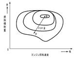
- FIG. 3 is a map showing the relationship among the engine speed, the fuel injection amount, and the EGR amount in the embodiment shown in FIG.
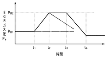
- FIG. 4 is a graph schematically showing the relationship between the opening / closing operation of the EGR control valve and the EGR gas pressure.
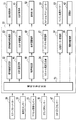
- FIG. 5 is a flowchart schematically showing a flow of control in the embodiment shown in FIG.
- FIG. 6 is a graph schematically showing the relationship between the fuel supply state and the intake pressure.
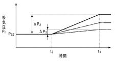
- FIG. 7 is a graph schematically showing the relationship between the opening timing of the EGR control valve and the intake pressure.
- FIG. 8 is a flowchart schematically showing a control flow in another embodiment of the present invention.
- Embodiments in which the operation control method for an internal combustion engine according to the present invention is applied to a compression ignition internal combustion engine will be described in detail with reference to FIGS.
- the present invention is not limited to these embodiments, and these can be further combined as necessary, or the configuration can be freely changed according to the characteristics required for the subject of the present invention. It is.
- the present invention is also effective for a spark ignition type internal combustion engine in which gasoline, alcohol, LNG (liquefied natural gas) or the like is used as fuel and is ignited by a spark plug.
- FIG. 1 shows the concept of the engine system in the present embodiment
- FIG. 2 shows control blocks in this engine system. That is, the engine 10 in the present embodiment is a compression ignition type multi-cylinder internal combustion engine that spontaneously ignites by directly injecting light oil as fuel into the combustion chamber 12 in a compressed state from the fuel injection valve 11.
- the present invention can be applied even to a single-cylinder internal combustion engine.
- a valve mechanism (not shown) and the previous fuel injection valve 11 are incorporated in a cylinder head 15 formed with an intake port 13 and an exhaust port 14 respectively facing the combustion chamber 12.
- the valve mechanism in the present embodiment includes an intake valve 16 that opens and closes the intake port 13 and an exhaust valve 17 that opens and closes the exhaust port 14.
- the opening and closing timings of the intake valve 16 and the exhaust valve 17 are set according to the operating state of the engine 10. It can be changed. However, it is also possible to employ a valve operating mechanism in which the opening / closing timings of the intake valve 16 and the exhaust valve 17 are fixed.
- the fuel injection valve 11 is arranged facing the center of the upper end of the combustion chamber 12 so as to be sandwiched between the intake valve 16 and the exhaust valve 17.
- the fuel injection valve 11 in this embodiment is a direct injection single injection type in which light oil, which is fuel, is directly injected into the combustion chamber 12 before and after the end of the compression stroke, that is, before and after the compression top dead center of the piston 18.
- light oil which is fuel
- the amount and injection timing of fuel from the fuel injection valve 11 is supplied to the combustion chamber 12, the ECU (E lectronic C ontrol U nit ) 20 based on operating conditions of the vehicle including the depression amount of the accelerator pedal 19 by the driver Be controlled.
- the amount of depression of the accelerator pedal 19 is detected by an accelerator opening sensor 21, and the detection information is output to the ECU 20. More specifically, based on the driving state of the vehicle including the detection signal from the accelerator opening sensor 21, the fuel injection setting unit 22 of the ECU 20 drives the engine 10, that is, the fuel injection amount from the fuel injection valve 11, That is, the supply amount and the injection timing are set.
- the fuel injection valve drive unit 23 of the ECU 20 drives the fuel injection valve 11 so that fuel corresponding to the fuel injection amount set by the fuel injection setting unit 22 is injected at a set injection timing.
- a throttle valve 25 for adjusting the opening degree of the intake passage 24a is incorporated in the middle of the intake pipe 24 that is connected to the cylinder head 15 so as to communicate with the intake port 13 and defines the intake passage 24a together with the intake port 13. It is.
- the opening of the throttle valve 25 is set by the throttle opening setting unit 26 of the ECU 20 based on the depression amount of the accelerator pedal 19 detected by the accelerator opening sensor 21 and the driving state of the vehicle. Then, the throttle valve drive unit 27 of the ECU 20 drives the throttle valve 25 via the throttle actuator 28 so that the opening set by the throttle opening setting unit 26 is obtained.
- a crank angle sensor 32 that detects the rotational phase of the crankshaft 31 to which the piston 18 is connected via the connecting rod 30, that is, the crank angle, and outputs it to the ECU 20 is attached to the cylinder block 29 in which the piston 18 reciprocates. It has been.
- the ECU 20 grasps the rotational phase of the crankshaft 31 and the engine rotational speed in real time based on the information from the crank angle sensor 32.
- the engine 10 in the present embodiment is assembled with an exhaust turbine supercharger 33, an exhaust purification device 34, and an EGR device 36 that guides part of the exhaust gas flowing in the exhaust passage 35a to the intake passage 24a.
- An exhaust turbine supercharger (hereinafter simply referred to as a supercharger) 33 supercharges the combustion chamber 12 using the kinetic energy of the exhaust gas flowing through the exhaust passage 35a, increases the intake air density, and increases the intake air flow rate. It is for increasing.
- the supercharger 33 includes a compressor 33a and a turbine 33b that rotates integrally with the compressor 33a.
- the compressor 33 a is incorporated in the intake pipe 24 located upstream of the throttle valve 25.
- the turbine 33 b is incorporated in the middle of the exhaust pipe 35 connected to the cylinder head 15 so as to communicate with the exhaust port 14.
- an intercooler is provided in the middle of the intake passage 24a between the compressor 33a and the surge tank 37. 38 is incorporated.
- the intake pipe 24 upstream of the compressor 33a of the supercharger is provided with an air flow meter 39 that detects the flow rate of the intake air flowing through the intake passage 24a and outputs it to the ECU 20.
- the exhaust gas purification device 34 for detoxifying harmful substances generated by the combustion of the air-fuel mixture in the combustion chamber 12 includes an exhaust pipe 35 that defines an exhaust passage 35a downstream of the turbine 33b of the supercharger 33. It is arranged on the way.
- the EGR device 36 intended to reduce nitrogen oxides in the exhaust gas exchanges heat with an EGR pipe 40 that defines an EGR passage 40a, an EGR control valve 41 and an on-off valve 42 that are provided separately from the EGR pipe 40. And a container 43.
- the EGR pipe 40 has one end communicating with the exhaust pipe 35 that defines the exhaust passage 35 a together with the exhaust port 14, and the other end with the above-described throttle valve 25 and the surge tank 37 disposed downstream of the throttle valve 25.
- An EGR control valve 41 which is disposed on one end side of the EGR pipe 40 in the vicinity of the connection portion between the intake pipe 24 and the EGR pipe 40 and whose operation is controlled by the ECU 20, is recirculated from the EGR passage 40a to the intake passage 24a.
- the flow rate of the exhaust gas as EGR gas is controlled.
- the EGR amount setting unit 44 of the ECU 20 has an EGR amount map as shown in FIG. 3 in which the engine 10 is set in relation to the engine speed and the fuel injection amount.
- the EGR amount setting unit 44 sets the EGR amount to be recirculated into the combustion chamber 12 from this map, that is, the opening degree of the EGR control valve 41, and outputs this to the EGR valve drive unit 45 of the ECU 20.
- the EGR valve drive unit 45 controls the EGR control valve 41 so that the opening degree set by the EGR amount setting unit 44 is obtained, and otherwise, the EGR control valve 41 basically closes the EGR passage 40a. 41 is kept closed.
- the on-off valve 42 disposed on the connection portion side between the exhaust pipe 35 and the EGR pipe 40 switches the EGR passage 40a between the fully open state and the fully closed state by the on / off valve driving unit 46 of the ECU 20.
- the on-off valve 42 is held in a fully closed state when a part of the exhaust gas flowing through the exhaust passage 35a is introduced into the EGR passage 40a as an EGR gas and temporarily confined. Retained.
- the EGR pipe 40 is provided with an EGR gas pressure sensor 47 that detects the pressure Pe of the EGR gas interposed in the EGR passage 40 a between the EGR control valve 41 and the on-off valve 42 and outputs the detected pressure Pe to the ECU 20. Yes.
- the interval between the EGR control valve 41 and the on-off valve 42 is set so that the volume of the EGR passage 40a partitioned by the closed EGR control valve 41 and the on-off valve 42 is substantially the same as the displacement of the engine 10.
- the inner diameter of the EGR passage 40a between them is set appropriately.
- the heat exchanger 43 for reducing the temperature of the exhaust gas flowing into the EGR passage 40a is an EGR located between the other end side of the EGR pipe 40, that is, between the connection part of the exhaust pipe 35 and the EGR pipe 40 and the on-off valve 42. It is arranged in the middle of the tube 40.
- the intake air supplied into the combustion chamber 12 together with the exhaust gas recirculated into the intake passage 24a via the EGR passage 40a forms a mixture with the fuel injected from the fuel injection valve 11 into the combustion chamber 12.
- the piston 18 spontaneously ignites and burns immediately before the compression top dead center of the piston 18, and the exhaust generated thereby is discharged from the exhaust pipe 35 into the atmosphere through the exhaust purification device 34.
- the action of the EGR device 36 causes a decrease in the intake gas temperature due to an increase in the CO 2 concentration contained in the intake air, resulting in a decrease in the combustion gas temperature, thereby suppressing the amount of nitrogen oxides generated with combustion.
- the Rukoto The Rukoto.
- the engine system according to the present embodiment can effectively perform EGR control when the engine 10 is restarted based on the engine start request after the engine 10 is temporarily stopped based on the engine stop request. Therefore, prior to the temporary stop of the engine 10 based on the engine stop request, the EGR control valve 41 is closed prior to the closing operation of the on-off valve 42, and the EGR passage 40a has a high pressure and low oxygen concentration. Exhaust gas is temporarily stored as EGR gas. Then, when the engine 10 is restarted based on the engine start request, the EGR control valve 41 is closed prior to the closing operation of the on-off valve 42, and the EGR gas confined in the EGR passage 40a is taken in. It returns to the passage 24a. Thus, effective EGR control can be performed for the first explosion cylinder when the engine 10 is restarted.
- the “engine stop request” in the present invention refers to a case where the depression amount of the accelerator pedal 19 is zero and the vehicle speed is zero during the operation of the engine 10.
- the “engine start request” in the present invention refers to a case where the driver depresses the accelerator pedal 19 for starting the vehicle from a state where the engine 10 is stopped by the “engine stop request”.
- the ECU 20 in the present embodiment includes a failure determination unit 48 for detecting whether or not the opening / closing operation of the EGR control valve 41 and the opening / closing valve 42 is abnormal, and a display driver 49.
- the failure determination unit 48 compares the target EGR amount set based on the operating state of the engine 10 with the actual EGR amount due to the change in the opening degree of the EGR control valve 41 driven based on the target EGR amount. When the difference is more than the value, it is determined that the EGR device 36 is abnormal. That is, since at least one of the EGR control valve 41 and the on-off valve 42 is fixed in a closed state, it can be determined that the normal flow of EGR gas is hindered with respect to the EGR passage 40a.
- the target EGR amount is set by the EGR amount setting unit 44, and the actual EGR amount is calculated by an operation state determination unit 51 (to be described later) of the ECU 20 based on outputs from the air flow meter 39, the intake pressure sensor 50, and the like. Is done.
- the absolute value ⁇ Q n of the difference between the target EGR amount and the actual EGR amount is compared with a preset threshold value ⁇ Q R, and when ⁇ Q n > ⁇ Q R , the EGR device 36 is abnormal, that is, It is determined that at least one of the EGR control valve 41 and the on-off valve 42 is fixed in the closed state.
- the EGR device 36 When the EGR device 36 is determined to be abnormal, further comparing the malfunction determining unit 48 and a pressure P e of the EGR gas detected by the intake air pressure P I and the EGR gas pressure sensor 47 which is detected by the intake pressure sensor 50 To do. Then, it is determined that the pressure P e of the intake air pressure P I is EGR gas approximately equal, and the opening and closing valve 42 since it is expected that are fixed in the closed state, there is a malfunction in the opening and closing valve 42. Conversely, if the intake air pressure P I is determined to be different from the pressure P e of the EGR gas, the EGR control valve 41 is expected to have stuck in the closed state, the abnormal operation in the EGR control valve 41 Judge that there is.
- an intake pressure sensor 50 is provided in the intake pipe 24 downstream of the communication portion with the EGR pipe 40, and the intake pressure sensor 50 is a pressure P n of the intake air flowing therethrough. Is output to the ECU 20.
- the ECU 20 follows the EGR control valve 41 according to the stop request to the engine 10. Close. Next, the on-off valve 42 is closed after a predetermined time, and a part of the exhaust gas flowing through the exhaust passage 35a is temporarily confined in the EGR passage 40a as EGR gas. Thereafter, the fuel injection from the fuel injection valve 11 is stopped, and the engine 10 is temporarily shifted to the stop state until the engine start request is made again, and the throttle valve 25 is also maintained in the fully closed state at the same time.
- the EGR control valve 41 is temporarily fully opened and then waits in the fully closed state again. That is, after the engine 10 is temporarily stopped, the EGR control valve 41 is temporarily opened, so that part of the EGR gas temporarily confined flows out to the intake passage 35a side, and the engine 10 is restarted. It enables effective EGR control for the first explosion cylinder when it is started.
- the relationship between such EGR opening and closing the EGR gas pressure P e of the control valve 41 is schematically shown in FIG. That is, closes the EGR control valve 41 at time t 1, increases the EGR gas pressure P e is closed off valve 42 at time t 2, the temporarily EGR control valve 41 at time t 3 At time t 4, the EGR control valve 41 is held again to wait for an engine start request. In this case, if there is no abnormality in the valve closing operation of the EGR control valve 41 and the opening and closing valve 42, the change in the EGR gas pressure P e as shown by the solid line in FIG. 4 occurs.
- the EGR control valve 41 when the EGR control valve 41 is stuck in an open state, increase of the EGR gas pressure P e as indicated by a chain line in FIG 4 between extending from time t 1 to time t 2 does not occur. Therefore, in this case, it can be determined that the EGR control valve 41 is stuck in the open state.
- the on-off valve 42 may have stuck in an open state, decrease in the EGR gas pressure P e as shown by a two-dot chain line in FIG. 4 between extending from time t 2 to time t 3 does not occur. Therefore, in this case, it can be determined that the on-off valve 42 is stuck in the open state.
- the previous failure determination unit 48 also stores a map corresponding to FIG. 4, and based on detection information from the EGR gas pressure sensor 47 associated with the closing operation of the EGR control valve 41 and the on-off valve 42, the EGR control valve The operation abnormality of 41 and the on-off valve 42 is determined.
- the determination result in the failure determination unit 48 as described above is output to the display unit drive unit 49.
- the indicator drive unit 49 is for informing the driver that there is an abnormality in the opening operation of the EGR control valve 41 and the on-off valve 42 based on the determination result of the failure determination unit 48, and a warning indicator for that purpose. 52 is provided in a vehicle interior (not shown).
- the warning indicator 52 may be any device that can alert the driver of the vehicle using hearing or vision.
- the ECU 20 includes a microcomputer including a CPU, ROM, RAM, A / D converter, input / output interface, etc. (not shown).
- the ECU 20 in the present embodiment grasps the operating state of the engine 10 and the vehicle on which the engine 10 is mounted based on the detection information from the various sensors 21, 32, 50, 51, 54 and the air flow meter 39 described above. . Then, the operations of the fuel injection valve 11, the throttle actuator 28, the EGR control valve 41, the on-off valve 42, the engine starter motor 53, and the like are controlled so that the engine 10 is operated in accordance with a preset program. Further, failure determination of the EGR control valve 41 and the on-off valve 42 is also performed. For this reason, the ECU 20 in this embodiment further includes a starter motor drive unit 54 in addition to the previous driving state determination unit 51 and the like.
- the driving state determination unit 51 is based on detection information from the accelerator opening sensor 21, the crank angle sensor 32, the exhaust pressure sensor 50, the EGR gas pressure sensor 47, the air flow meter 39, the intake pressure sensor 50, and the like. Understand the driving status of Further, the operating state determination unit 51 also determines whether or not there is an engine stop request or an engine start request.
- the starter motor drive unit 54 controls the operation of the engine starter motor 53 connected to the crankshaft 31 via a joint (not shown) based on an ON signal of an ignition key switch (not shown) or a previous engine start request.
- the engine start motor 53 performs motoring of the engine 10.
- step S11 it is determined whether or not the absolute value ⁇ Q n of the difference between the target EGR amount and the actual EGR amount is equal to or less than the threshold value ⁇ Q R.
- the absolute value ⁇ Q n of the difference between the target EGR amount and the actual EGR amount is equal to or less than the threshold value ⁇ Q R , that is, there is no abnormality in the EGR device 36 (the EGR control valve 41 and the on-off valve 42 are fixed in the closed state). If not, the process proceeds to step S12. In step S12, it is determined whether or not there is an engine stop request. If it is determined that there is no engine stop request, the process returns to step S11 and the above determination is repeated.
- step S12 If it is determined in step S12 that there is an engine stop request, the process proceeds to step S13, the EGR control valve 41 is closed, and a part of the exhaust gas flowing through the exhaust passage 35a is taken into the EGR passage 40a as EGR gas. . Then counts up the timer in step S14, it is determined whether the count value C n of the timer has reached the predetermined value C R1 set in advance in step S15. The steps S14 and S15 are repeated until the count value C n of the timer reaches a predetermined value C R1 .
- step S15 When it is determined in step S15 that the timer count value C n has reached the predetermined value C R1 , that is, an amount of exhaust corresponding to the exhaust amount of the engine 10 has been led to the EGR passage 39a as EGR gas, The process proceeds to step S16.
- step S16 in step resets the count value C n of the timer to 0, the EGR gas pressure P immediately before further EGR gas pressure P e detected by the EGR gas pressure sensor 47 at step S17 to close the EGR control valve 41 Determine whether it is higher than R1 .
- the EGR control valve 41 higher than the EGR gas pressure P R1 immediately before EGR gas pressure P e is closed the EGR control valve 41, that is, when it is determined that the EGR control valve 41 is normally closed is to S18 step Then, the on-off valve 42 is closed. Then, again counts up the timer in step S19, it is determined whether the count value C n of the timer has reached the predetermined value C R2 set in advance in step S20. Then, until the count value C n of the timer reaches a predetermined value C R2, S19, S20 steps are repeated.
- step S20 If it is determined in step S20 that the timer count value C n has reached the predetermined value C R2 , the process proceeds to step S21 and the timer count value C n is reset to zero.
- the predetermined value C R2 if there is leakage of EGR gases trapped in the EGR passage 40a, are those which correspond to the time required to decrease the degree of the EGR gas pressure P e can be detected by the EGR gas pressure sensor 47 .
- step further determines whether substantially the same at S22 in step EGR gas pressure P e detected by the EGR gas pressure sensor 47 and the EGR gas pressure P R2 at the time of the closed-off valve 42.
- the same EGR gas pressure P e is the EGR gas pressure P R2, that is, when it is determined that the on-off valve 42 is normally closed is from the fuel injection valve 11 goes to S23 in step The fuel injection is stopped and the engine 10 is temporarily stopped. At the same time, the throttle valve 25 is kept fully closed.
- step S24 the EGR control valve 41 is temporarily shifted to the fully opened state, and a part of the EGR gas confined in the EGR passage 40a is sent to the intake passage 35a.
- step S25 the EGR control is performed. The valve 41 is held in the fully closed state again to wait for an engine start request.
- step S11 the absolute value ⁇ Q n of the difference between the target EGR amount and the actual EGR amount is larger than the threshold value ⁇ Q R , that is, there is an abnormality in the EGR device 36 (EGR control valve 41 / open / close in the closed state) If it is determined that the valve 42 is fixed), the process proceeds to step S26.
- step S26 determines substantially the same as the intake air pressure P I of EGR gas pressure P e is detected by the intake pressure sensor 50.
- EGR gas pressure P e is approximately the same as the intake air pressure P I, that is, when the opening and closing valve 42 is determined to be stuck in the closed state, transition to the failure of the on-off valve 42 in step S27 Information is output to the display driver 49.
- the display driver 49 drives the warning display 58 and ends the series of determinations.
- EGR gas pressure P e is not the same as the intake air pressure P I at step S26, that is, when the EGR control valve 41 is determined to be stuck in the closed state, the process proceeds to step S29 EGR The failure information of the control valve 41 is output to the display driver 49.
- step S28 the display drive unit 49 drives the warning display 58 and ends the series of determinations.
- the EGR gas pressure P e in step S17 is not higher than the EGR gas pressure P R1 immediately before closing the EGR control valve 41, that is, when it is determined that the EGR control valve 41 is stuck in the open state Shifts to step S30.
- the failure information of the EGR control valve 41 is output to the display driver 49, and the display driver 49 drives the warning display 58 in step S28, and the series of determinations is completed.
- the EGR gas pressure P e is not the same as the EGR gas pressure P R2 at the time of the closed-off valve 42 at S22 in step, that is, when it is determined that the on-off valve 42 is stuck in the open state , S31 is entered.
- the failure information of the on-off valve 42 is output to the display unit drive unit 49, and the display unit drive unit 49 drives the warning display unit 58 in step S28, thus completing a series of determinations.
- the EGR gas pressure sensor 47 is used to detect the pressure P e of the EGR gas interposed in the EGR passage as the atmospheric pressure facing the EGR control valve 41, but the atmosphere facing the EGR control valve 41 is used. it is also possible to detect the intake air pressure P I as pressure.
- whether or not the EGR control valve 41 is abnormal is determined based on the amount of pressure drop from the intake pressure P S1 immediately before the fuel injection from the fuel injection valve 11 stops to the intake pressure P I when the engine 10 stops. You can do it. That is, if the pressure drop amount from the intake pressure P S1 immediately before the stop of fuel injection does not decrease by a predetermined pressure ⁇ P 1 or more, the failure determination unit 48 is stuck in the open state of the EGR control valve 41. Is determined. Such a state is schematically shown in FIG. That is, when the fuel supply is stopped at time t2 ′ and the engine 10 is stopped at time t3 ′ , the intake pressure P I is indicated by a solid line in FIG.
- FIG. 7 schematically shows the change in the above. That is, the EGR control valve 41 is temporarily opened at time t 3, the EGR control valve 41 is again closed at time t 4 , and the EGR control valve 41 is opened or closed when waiting for an engine start request. If the valve 42 is normal, the intake pressure P I increases by [Delta] P 2 as indicated by a solid line in FIG. However, when the on-off valve 42 is fixed in the open state, as shown by the one-dot chain line in FIG.
- ⁇ P 3 is slightly smaller than the pressure P S2 immediately before the time t3 when the EGR control valve 41 switches to the open state. Only rises. Also, opening and closing valve 42 is normal, if not move smoothly when there is reluctant to closing of the EGR control valve 41, as shown by the two-dot chain line in FIG. 7, the amount of increase in the intake air pressure P I is It falls between ⁇ P 3 and ⁇ P 2 .
- step S12 The control procedure according to the present embodiment for diagnosing the failure of the EGR control valve 41 and the on-off valve 42 as described above is performed according to the flowchart shown in FIG. 8, and the same step number is assigned to the same processing as the previous procedure. is doing. That is, it is first determined whether or not there is an engine stop request in step S12. If it is determined that there is no engine stop request, step S12 is repeated until there is an engine stop request.
- step S12 If it is determined in step S12 that there is an engine stop request, the process proceeds to step S13, the EGR control valve 41 is closed, and a part of the exhaust gas flowing through the exhaust passage 35a is taken into the EGR passage 40a as EGR gas. . Then counts up the timer in step S14, it is determined whether the count value C n of the timer has reached the predetermined value C R1 at step S15. The steps S14 and S15 are repeated until the count value C n of the timer reaches a predetermined value C R1 .
- step S15 When it is determined in step S15 that the timer count value C n has reached the predetermined value C R1 , that is, an amount of exhaust corresponding to the exhaust amount of the engine 10 has been led to the EGR passage 39a as EGR gas, The process proceeds to step S16.
- step S16 the timer count value C n is reset to 0, and in step S1181, the on-off valve 42 is closed, fuel injection from the fuel injection valve 11 is stopped, and the engine 10 is temporarily stopped. At the same time, the throttle valve 25 is kept fully closed.
- step S19 Thereafter, again counts up the timer in step S19, it is determined whether the count value C n of the timer has reached the predetermined value C R2 at step S20. Then, until the count value C n of the timer reaches a predetermined value C R2, S19, S20 steps are repeated.
- step S20 If it is determined in step S20 that the timer count value C n has reached the predetermined value C R2 , the process proceeds to step S21 and the timer count value C n is reset to zero.
- the predetermined value C R2 are those when there is leakage of EGR gases trapped in the EGR passage 40a, corresponding to the time required to decrease the amount [Delta] P 1 of the intake pressure P I that can be detected by the intake pressure sensor 50 is there.
- step S21 whether or not further lowered S221 intake pressure sensor 50 intake air pressure P I detected the predetermined pressure [Delta] P 1 or the intake pressure P S1 immediately before stopping the fuel injection by the step Determine.
- step S24 when it is determined that the intake pressure P I is lower than the intake pressure P IS just before the fuel injection is stopped by a predetermined pressure ⁇ P 1 or more, that is, the EGR control valve 41 is normally closed, Shifting to step S24, the EGR control valve 41 is temporarily shifted to the fully open state. Then, again counts up the timer in step S241, it is determined whether the count value C n of the timer has reached the predetermined value C R3 at step S242. Then, until the count value C n of the timer reaches a predetermined value C R3, it is repeated steps S241, S242.
- step S242 If it is determined in step S242 that the timer count value C n has reached the predetermined value C R3 , the process proceeds to step S243 and the timer count value C n is reset to zero.
- the predetermined value C R3 is an intake pressure that can be detected by the intake pressure sensor 50 when a part of the EGR gas confined in the EGR passage 40a is led to the intake passage 35a by the temporary opening operation of the EGR control valve 41. This corresponds to the time required to increase the pressure P I.
- the intake pressure P I detected by the intake pressure sensor 50 in the step of S244 is a predetermined pressure ⁇ P 2 higher than the intake pressure P S2 immediately before the EGR control valve 41 is temporarily shifted to the open state. As described above, it is determined whether or not it is rising. Here, the intake pressure P I has increased by a predetermined pressure ⁇ P 2 or more than the intake pressure P S2 immediately before the EGR control valve 41 is shifted to the open state, that is, the EGR control valve 41 and the on-off valve 42 are normally closed. If it is determined that it is, the process proceeds to step S25. Then, the EGR control valve 41 is held in the fully closed state again to wait for an engine start request.
- step S30 a decrease is Tokoro than pressure [Delta] P 1 from the intake pressure P IS immediately before the intake air pressure P I at S221 step stops fuel injection, that is, when the EGR control valve 41 is stuck in the open state If it is determined, the process proceeds to step S30.
- the failure information of the on-off valve 42 is output to the display unit drive unit 49, and then the display unit drive unit 49 drives the warning display unit 58 in step S28.
- step S244 If it is determined in step S244 that the increase amount of the intake pressure P I is less than the predetermined pressure ⁇ P 2 than the intake pressure P S2 immediately before the EGR control valve 41 is shifted to the open state, the step of S245 is performed. Migrate to Here, it is determined whether the pressure [Delta] P 3 or less at relative intake pressure P S1 immediately before the rise of the intake pressure P I detected by the intake pressure sensor 50 to stop fuel injection. In step S245, it is determined that the amount of increase in the intake pressure P I is equal to or less than a predetermined pressure ⁇ P 3 with respect to the intake pressure P S1 immediately before stopping fuel injection, that is, the on-off valve 42 is fixed in the open state. If so, the process proceeds to step S31. Then, the failure information of the on-off valve 42 is output to the display driver 49, and then the display driver 49 drives the warning display 58 in step S28.
- step S246 the failure information of the EGR control valve 41 is output to the display driver 49, and then the display driver 49 drives the warning display 58 in step S28, and the series of determinations is completed.
Landscapes
- Engineering & Computer Science (AREA)
- Chemical & Material Sciences (AREA)
- Combustion & Propulsion (AREA)
- Mechanical Engineering (AREA)
- General Engineering & Computer Science (AREA)
- Exhaust-Gas Circulating Devices (AREA)
Abstract
一端が吸気通路(24a)に連通すると共に他端が排気通路(35a)に連通し、エンジン(10)から排出される排気の一部をEGRガスとして吸気通路(24a)に導くためのEGR通路(40a)と、このEGR通路(40a)の一端側に配されてEGR通路(40a)を流れるEGRガスの流量を制御するためのEGR制御弁(41)と、EGR通路(40a)の他端側に配されてEGR通路(40a)を開閉するための開閉弁(42)とを具えた本発明によるEGR装置(36)の故障診断方法は、エンジン(10)に対する停止要求に従ってEGR制御弁(41)を閉止した後、EGR制御弁(41)に臨む雰囲気圧力を検出し、この検出結果に基づいてEGR制御弁(41)および開閉弁(42)の少なくとも一方の動作異常の有無を判定する。
Description
本発明は、吸気通路に連通するEGR通路の一端側に配されてEGRガスの流量を制御するためのEGR制御弁と、排気通路に連通するEGR通路の他端側に配されてEGR通路を開閉するための開閉弁とを具えた排気還流装置の故障診断方法に関する。
排気通路内を流れる排気の一部を吸気通路から燃焼室内に戻し、燃焼室内における混合気の燃焼温度を低下させることにより、排気中に占める窒素酸化物の割合を低減させるようにしたEGR(Exhaust Gas Recirculation:排気還流)装置が知られている。このEGR装置においては、両端が吸気通路と排気通路とに連通するEGR通路の途中にこのEGR通路を開閉し得るEGR制御弁を介装し、所定の運転領域にて排気を吸気通路側へ還流させている。
近年、排気の浄化に対する社会的要求が著しく高まっており、このような観点から車両が停止中の場合には内燃機関の作動を停止させ、燃料の無駄な消費を抑制すると同時に二酸化炭素の無駄な排出を防止する、いわゆるアイドルストップ制御も推進されている。しかしながら、このようなアイドルストップ制御における内燃機関の再始動時には、EGR通路には有効となる排気が介在していないため、特に始動の最初に燃料と共に燃焼室に供給される吸気に対し、排気を含ませることが困難である。
このような問題を解決する技術が特許文献1にて提案されている。すなわち、アイドルストップ制御において、内燃機関の停止時にEGR通路にEGRガスを一時的に貯留しておき、内燃機関の再始動時にEGRガスを吸気に加えて供給できるようにしている。
特許文献1においては、EGR通路にEGRガスを一時的に貯留する必要があるため、EGR通路の一端側に配されたEGR制御弁に加えてEGR通路の他端側に開閉可能な開閉弁を組み込んでいる。
しかしながら、EGR制御弁と開閉弁とを用いてEGR通路にEGRガスを一時的に閉じ込めるようにした場合、EGR制御弁や開閉弁にHC(Hydro Carbons:炭化水素)やPM(Particulate Matter:粒子状物質)などが付着堆積することとなる。結果として、EGR制御弁や開閉弁の円滑な開閉動作が経時的に阻害される可能性があった。
このため、EGR制御弁や開閉弁の動作異常の有無を定期的に確認し、異常が見つかった場合には整備や修理などを行って、常にエンジンの円滑な作動を維持することが望まれる。本発明の目的は、このような知見に基づき、EGR制御弁や開閉弁の動作異常の有無を簡単に確認し得る排気還流装置の故障診断方法を提供することにある。
本発明は、一端が吸気通路に連通すると共に他端が排気通路に連通し、内燃機関から排出される排気の一部をEGRガスとして吸気通路に導くためのEGR通路と、このEGR通路の一端側に配されて当該EGR通路を流れるEGRガスの流量を制御するためのEGR制御弁と、EGR通路の他端側に配されてEGR通路を開閉するための開閉弁とを具えた排気還流装置の故障診断方法であって、内燃機関に対する停止要求に従ってEGR制御弁を閉止するステップと、EGR制御弁を閉止した後にこのEGR制御弁に臨む雰囲気圧力を検出するステップと、検出された雰囲気圧力に基づいてEGR制御弁および開閉弁の少なくとも一方の動作異常の有無を判定するステップとを具えたことを特徴とするものである。
本発明による排気還流装置の故障診断方法において、EGR制御弁に臨む雰囲気圧力がEGR通路に介在するEGRガスの圧力か、または吸気圧であってよい。
EGR制御弁に臨む雰囲気圧力がEGR通路に介在するEGRガスの圧力の場合、EGR制御弁を閉止した後に開閉弁を閉止するステップをさらに具えることができる。この場合、雰囲気圧力としてEGRガスの圧力を検出するステップは、開閉弁を閉止するステップの前に行われるものであってよい。ここで、EGR制御弁および開閉弁の少なくとも一方の動作異常の有無を判定するステップは、雰囲気圧力として検出されたEGRガスの圧力があらかじめ設定された値よりも低い場合、EGR制御弁に動作異常があると判定することができる。
EGR制御弁に臨む雰囲気圧力がEGR通路に介在するEGRガスの圧力の場合、EGR制御弁を閉止した後に開閉弁を閉止するステップをさらに具えることができる。この場合、雰囲気圧力としてEGRガスの圧力を検出するステップは、開閉弁を閉止するステップの後に行われるものであってよい。ここで、EGR制御弁および開閉弁の少なくとも一方の動作異常の有無を判定するステップは、雰囲気圧力として検出されたEGRガスの圧力があらかじめ設定された値よりも低い場合、開閉弁に動作異常があると判定することができる。
開閉弁を閉止した後に内燃機関に対する燃料供給を停止するステップをさらに具え、雰囲気圧力としてEGRガスの圧力を検出するステップは、内燃機関に対する燃料供給を停止するステップの前に行われるものであってよい。
排気還流装置の異常の有無を判定するステップをさらに具え、内燃機関に対する停止要求に従ってEGR制御弁を閉止するステップは、排気還流装置に異常がないと判定された場合に行われるものであってよい。ここで、排気還流装置に異常があると判定された場合、吸気圧とEGR通路に介在するEGRガスの圧力とを比較するステップと、この比較結果に基づいてEGR制御弁および開閉弁の動作異常の有無を判定するステップとをさらに具えることができる。この場合、EGR制御弁および開閉弁の動作異常の有無を判定するステップは、吸気圧がEGRガスの圧力とほぼ同じ場合に開閉弁に動作異常があると判定し、吸気圧がEGRガスの圧力と異なっている場合にEGR制御弁に動作異常があると判定することができる。
排気還流装置の異常の有無を判定するステップは、内燃機関の運転状態に基づいて設定される目標EGR量と実際のEGR量とを比較するステップを含むことができる。
一方、EGR制御弁に臨む雰囲気圧力が吸気圧の場合、EGR制御弁を閉止した後に内燃機関に対する燃料供給を停止すると共に開閉弁を閉止するステップをさらに具えることができる。この場合、EGR制御弁に臨む雰囲気圧力として吸気圧を検出するステップは、内燃機関に対する燃料供給を停止すると共に開閉弁を閉止するステップの後に行われるものであってよい。また、内燃機関に対する燃料供給を停止すると共に開閉弁を閉止した後にEGR制御弁を一時的に開弁するステップと、EGR制御弁を一時的に開弁した後、このEGR制御弁を再び閉止するステップとをさらに具えることができる。この場合、EGR制御弁に臨む雰囲気圧力として吸気圧を検出するステップは、EGR制御弁を一時的に開弁するステップの前に行われるものであってよい。ここで、EGR制御弁および開閉弁の少なくとも一方の動作異常の有無を判定するステップは、検出された雰囲気圧力としての吸気圧があらかじめ設定された値以上の場合、EGR制御弁に動作異常があると判定することができる。
EGR制御弁に臨む雰囲気圧力として吸気圧を検出するステップは、EGR制御弁を一時的に開弁するステップとEGR制御弁を再び閉止するステップとの間に行われるものであってよい。ここで、EGR制御弁および開閉弁の少なくとも一方の動作異常の有無を判定するステップは、検出された吸気圧が予め設定された値以上の場合、開閉弁に動作異常があると判定し、その逆の場合にはEGR制御弁に動作異常があると判定することができる。
本発明の排気還流装置の故障診断方法によると、内燃機関に対する停止要求に従ってEGR制御弁を閉止した後、EGR制御弁に臨む雰囲気圧力を検出してEGR制御弁および開閉弁の少なくとも一方の動作異常の有無を判定することができる。
EGR制御弁を閉止した後、開閉弁を閉止する前に雰囲気圧力として検出されるEGRガスの圧力があらかじめ設定された値よりも低い場合、EGR制御弁に動作異常があると判定することができる。
EGR制御弁を閉止した後に開閉弁を閉止し、次いで雰囲気圧力として検出されるEGRガスの圧力があらかじめ設定された値よりも低い場合、開閉弁に動作異常があると判定することができる。
開閉弁を閉止した後に雰囲気圧力としてEGRガスの圧力を検出し、次いで内燃機関に対する燃料供給を停止するようにした場合も同様に、開閉弁の動作異常の有無を判定することができる。
排気還流装置に異常がないと判定された場合、内燃機関に対する停止要求に従ってEGR制御弁を閉止することにより、EGR制御弁および開閉弁の少なくとも一方が開いた状態になってしまうような動作異常の有無を判定することができる。
排気還流装置に異常があるとの判定後、吸気圧がEGRガスの圧力とほぼ同じ場合に開閉弁に動作異常があると判定し、吸気圧がEGRガスの圧力と異なっている場合にEGR制御弁に動作異常があると判定することができる。
内燃機関の運転状態に基づいて設定される目標EGR量と、実際のEGR量とを比較することによって排気還流装置の異常の有無を判定することができる。
EGR制御弁を閉止した後に内燃機関に対する燃料供給を停止すると共に開閉弁を閉止し、次いでEGR制御弁に臨む雰囲気圧力として吸気圧を検出する場合、吸気圧センサーを用いて動作異常の有無を判定することができる。
内燃機関に対する燃料供給を停止すると共に開閉弁を閉止した後にEGR制御弁に臨む雰囲気圧力として検出される吸気圧があらかじめ設定された値以上の場合、EGR制御弁に動作異常があると判定することができる。
EGR制御弁を一時的に開弁した後、EGR制御弁に臨む雰囲気圧力として検出される吸気圧が予め設定された値以上の場合、開閉弁に動作異常があると判定し、逆の場合にはEGR制御弁に動作異常があると判定することができる。
本発明による内燃機関の運転制御方法を圧縮点火方式の内燃機関に応用した実施形態について、図1~図8を参照しながら詳細に説明する。しかしながら、本発明はこれらの実施形態のみに限らず、必要に応じてこれらをさらに組み合わせたり、本発明の適用対象となるものに要求される特性に応じてその構成を自由に変更することが可能である。例えば、ガソリンやアルコールまたはLNG(液化天然ガス)などを燃料としてこれを点火プラグにて着火させる火花点火方式の内燃機関に対しても本発明は有効である。
本実施形態におけるエンジンシステムの概念を図1に示し、このエンジンシステムにおける制御ブロックを図2に示す。すなわち、本実施形態におけるエンジン10は、燃料である軽油を燃料噴射弁11から圧縮状態にある燃焼室12内に直接噴射することにより、自然着火させる圧縮点火方式の多気筒内燃機関である。しかしながら、単気筒の内燃機関であっても本発明を適用し得ることは言うまでもない。
燃焼室12にそれぞれ臨む吸気ポート13および排気ポート14が形成されたシリンダーヘッド15には、図示しない動弁機構と、先の燃料噴射弁11とが組み込まれている。
本実施形態における動弁機構は、吸気ポート13を開閉する吸気弁16および排気ポート14を開閉する排気弁17を含み、エンジン10の運転状態に応じて吸気弁16および排気弁17の開閉タイミングを変更し得るものである。しかしながら、吸気弁16および排気弁17の開閉タイミングが固定された動弁機構を採用することも可能である。
燃料噴射弁11は、これら吸気弁16および排気弁17に挟まれるように燃焼室12の上端中央に臨んで配されている。本実施形態における燃料噴射弁11は、燃料である軽油を圧縮行程の終了前後、つまりピストン18の圧縮上死点前後に燃焼室12内に直接噴射する直噴単噴射型式のものである。しかしながら、この圧縮行程での燃料噴射に加え、着火遅れを抑制するために圧縮行程の途中においても噴射する多噴射型式のものを採用することも可能である。
燃料噴射弁11から燃焼室12内に供給される燃料の量および噴射タイミングは、運転者によるアクセルペダル19の踏み込み量を含む車両の運転状態に基づいてECU(Electronic Control Unit)20により制御される。アクセルペダル19の踏み込み量は、アクセル開度センサー21により検出され、その検出情報がECU20に出力される。より具体的には、アクセル開度センサー21からの検出信号を含む車両の運転状態に基づき、ECU20の燃料噴射設定部22がエンジン10の駆動トルク、つまり燃料噴射弁11からの燃料の噴射量、つまり供給量と、その噴射時期とを設定する。ECU20の燃料噴射弁駆動部23は、この燃料噴射設定部22にて設定された燃料噴射量に対応した燃料が設定された噴射時期に噴射されるように、燃料噴射弁11を駆動する。
吸気ポート13に連通するようにシリンダーヘッド15に連結されて吸気ポート13と共に吸気通路24aを画成する吸気管24の途中には、吸気通路24aの開度を調整するためのスロットル弁25が組み込まれている。このスロットル弁25の開度は、アクセル開度センサー21によって検出されるアクセルペダル19の踏み込み量や車両の運転状態に基づき、ECU20のスロットル開度設定部26にて設定される。そして、このスロットル開度設定部26にて設定された開度となるように、ECU20のスロットル弁駆動部27がスロットルアクチュエーター28を介してスロットル弁25の駆動を行う。
ピストン18が往復動するシリンダーブロック29には、連接棒30を介してピストン18が連結されるクランク軸31の回転位相、つまりクランク角を検出してこれをECU20に出力するクランク角センサー32が取り付けられている。ECU20は、クランク角センサー32からの情報に基づいてクランク軸31の回転位相やエンジン回転速度を実時間で把握する。
本実施形態におけるエンジン10には、排気タービン式過給機33と、排気浄化装置34と、排気通路35a内を流れる排気の一部を吸気通路24aに導くEGR装置36とが組み付けられている。
排気タービン式過給機(以下、単に過給機と記述する)33は、排気通路35aを流れる排気の運動エネルギーを利用して燃焼室12への過給を行い、吸気密度を高め、吸気流量を増加させるためのものである。この過給機33は、コンプレッサー33aとこのコンプレッサー33aと一体に回転するタービン33bとで主要部が構成されている。コンプレッサー33aは、スロットル弁25よりも上流側に位置する吸気管24の途中に組み込まれている。タービン33bは、排気ポート14に連通するようにシリンダーヘッド15に連結された排気管35の途中に組み込まれている。
なお、高温の排気にさらされるタービン33b側からの伝熱によりコンプレッサー33aを介して加熱される吸気温度を低下させるため、コンプレッサー33aとサージタンク37との間の吸気通路24aの途中には、インタークーラー38が組み込まれている。また、過給器のコンプレッサー33aよりも上流側の吸気管24には、ここの吸気通路24aを流れる吸気の流量を検出してこれをECU20に出力するエアーフローメーター39が設けられている。
燃焼室12内での混合気の燃焼により生成する有害物質を無害化するための排気浄化装置34は、過給機33のタービン33bよりも下流側の排気通路35aを画成する排気管35の途中に配されている。
排気中の窒素酸化物の低減を企図したEGR装置36は、EGR通路40aを画成するEGR管40と、このEGR管40に相隔てて設けられるEGR制御弁41および開閉弁42と、熱交換器43とを具えている。EGR管40は、排気ポート14と共に排気通路35aを画成する排気管35に一端が連通すると共に他端が上述したスロットル弁25とこのスロットル弁25よりも下流側に配されたサージタンク37との間の吸気管24内に連通している。
吸気管24とEGR管40との接続部分に近接してEGR管40の一端側に配され、ECU20によりその作動が制御されるEGR制御弁41は、EGR通路40aから吸気通路24aへと還流されるEGRガスとしての排気の流量を制御する。より具体的には、ECU20のEGR量設定部44は、エンジン10がエンジン回転速度と燃料噴射量とに関係付けて設定された図3に示す如きEGR量のマップを有している。EGR量設定部44は、このマップから燃焼室12内に還流すべきEGR量、つまりEGR制御弁41の開度を設定してこれをECU20のEGR弁駆動部45に出力する。EGR弁駆動部45は、EGR量設定部44にて設定された開度となるようにEGR制御弁41を制御し、それ以外の場合は基本的にEGR通路40aを塞ぐように、EGR制御弁41を閉止した状態に保持する。
排気管35とEGR管40との接続部分側に配される開閉弁42は、ECU20の開閉弁駆動部46によってEGR通路40aを全開状態または全閉状態に切り換える。この開閉弁42は、排気通路35aを流れる排気の一部をEGRガスとしてEGR通路40aに導入して一時的に閉じ込める際に全閉状態に保持されるが、それ以外は基本的に全開状態に保持される。
なお、EGR管40には、EGR制御弁41と開閉弁42との間のEGR通路40aに介在するEGRガスの圧力Peを検出してこれをECU20に出力するEGRガス圧センサー47が設けられている。
本実施形態では、閉止したEGR制御弁41と開閉弁42とで仕切られるEGR通路40aの容積がエンジン10の排気量とほぼ同じになるように、EGR制御弁41と開閉弁42との間隔およびこれらの間のEGR通路40aの内径が適切に設定されている。EGR通路40aに流入する排気の温度を低減させるための熱交換器43は、EGR管40の他端側、つまり排気管35およびEGR管40の接続部分と開閉弁42との間に位置するEGR管40の途中に配されている。
従って、EGR通路40aを介して吸気通路24a内に還流される排気と共に燃焼室12内に供給される吸気は、燃料噴射弁11から燃焼室12内に噴射される燃料と混合気を形成する。そして、ピストン18の圧縮上死点直前にて自然着火して燃焼し、これによって生成する排気が排気浄化装置34を通って排気管35から大気中に排出される。この場合、EGR装置36の作用によって吸気中に含まれるCO2濃度の増加に伴う吸気温度の低下が生じて燃焼ガス温度が低下するため、燃焼に伴って生成する窒素酸化物の量が抑制されることとなる。
本実施形態におけるエンジンシステムは、エンジン停止要求に基づく一時的なエンジン10の停止後にエンジン始動要求に基づいてエンジン10を再始動させる際、EGR制御を有効に行うことができようにしている。このため、エンジン停止要求に基づく一時的なエンジン10の停止前までに、開閉弁42の閉弁操作に先駆けてEGR制御弁41の閉弁操作を行い、EGR通路40aに高圧かつ低酸素濃度の排気をEGRガスとして一時的に貯留する。そして、エンジン始動要求に基づいてエンジン10を再始動させる際に、開閉弁42の閉弁操作に先駆けてEGR制御弁41の閉弁操作を行い、EGR通路40aに閉じ込められていたEGRガスを吸気通路24aに還流する。これによって、エンジン10の再始動時の初爆気筒に対しても有効なEGR制御が可能となる。
なお、本発明における「エンジン停止要求」とは、エンジン10の運転中にアクセルペダル19の踏み込み量が0かつ車速が0となった場合を言う。また、本発明における「エンジン始動要求」とは、「エンジン停止要求」によってエンジン10を停止した状態から、運転者が車両の発進のためにアクセルペダル19が踏み込まれた場合を言う。
このように、一時的にEGR制御弁41と開閉弁42とを閉止し、排気の一部をEGRガスとしてEGR通路40aに閉じ込める場合、HCやPMがこれらに付着堆積してその開閉動作が阻害されるおそれがある。このため、EGR制御弁41や開閉弁42の動作異常の有無を確認し、異常が見つかった場合には整備や修理などを行って、常にエンジン10の円滑な作動を維持することが望ましい。そこで、本実施形態におけるECU20は、EGR制御弁41や開閉弁42の開閉動作の異常の有無を検出するための故障判定部48と、表示器駆動部49とを有する。
故障判定部48は、エンジン10の運転状態に基づいて設定される目標EGR量と、これに基づいて駆動されるEGR制御弁41の開度の変更による実際のEGR量とを比較し、これが所定値以上相違している場合、EGR装置36が異常であると判定する。つまり、EGR制御弁41および開閉弁42の少なくとも一方が閉状態で固着しているため、EGR通路40aに関してEGRガスの正常な流れが阻害されていると判断することができる。ここで、目標EGR量はEGR量設定部44にて設定され、実際のEGR量はエアーフローメーター39や吸気圧センサー50などからの出力に基づいてECU20の後述する運転状態判定部51にて算出される。本実施形態では、目標EGR量と実際のEGR量との差の絶対値ΔQnと予め設定された閾値ΔQRと比較し、ΔQn>ΔQRの場合にEGR装置36が異常である、すなわちEGR制御弁41および開閉弁42の少なくとも一方が閉状態で固着していると判定する。EGR装置36が異常であると判定された場合、故障判定部48は吸気圧センサー50によって検出される吸気圧PIとEGRガス圧センサー47によって検出されるEGRガスの圧力Peとをさらに比較する。そして、吸気圧PIがEGRガスの圧力Peとほぼ等しい場合、開閉弁42が閉状態で固着していることが予測されるので、開閉弁42に動作異常があると判定する。逆に、吸気圧PIがEGRガスの圧力Peと相違していると判断した場合、EGR制御弁41が閉状態で固着していることが予測されるので、EGR制御弁41に動作異常があると判定する。
上述した故障判定を行うため、EGR管40との連通部分よりも下流側の吸気管24には先の吸気圧センサー50が設けられ、この吸気圧センサー50は、ここを流れる吸気の圧力Pnを検出してこれをECU20に出力する。
一方、ΔQn≦ΔQRの場合、すなわちEGR装置36のEGR制御弁41または開閉弁42が閉状態のまま固着していないと判定された場合、ECU20はエンジン10に対する停止要求に従ってEGR制御弁41を閉止する。次いで、所定時間後に開閉弁42を閉止し、排気通路35aを流れる排気の一部をEGRガスとしてEGR通路40aに一時的に閉じ込める。しかる後、燃料噴射弁11からの燃料の噴射を止め、再びエンジン始動要求があるまでエンジン10を一時的に停止状態に移行させ、スロットル弁25も同時に全閉状態に維持する。そして、エンジン始動要求にそなえてEGR制御弁41を一時的に全開状態にしてから再び全閉状態で待機する。つまり、エンジン10を一時的に停止した後、一時的にEGR制御弁41を開弁することにより、一時的に閉じ込めていたEGRガスの一部を吸気通路35a側に流出させ、エンジン10を再始動した際の初爆気筒に対する有効なEGR制御を可能としている。
このようなEGR制御弁41の開閉動作とEGRガス圧Peとの関係を模式的に図4に示す。すなわち、時刻t1にてEGR制御弁41を閉弁し、EGRガス圧Peが上昇し、時刻t2にて開閉弁42を閉弁し、時刻t3にてEGR制御弁41を一時的に開弁し、時刻t4にてEGR制御弁41を再び閉弁状態に保持し、エンジン始動要求を待つこととなる。この場合、EGR制御弁41および開閉弁42の閉弁動作に異常がなければ、図4の実線で示すようなEGRガス圧Peの変化が生ずる。しかしながら、EGR制御弁41が開弁状態で固着している場合、時刻t1から時刻t2に至る間において図4の一点鎖線で示すようなEGRガス圧Peの上昇は起こらない。従って、この場合にはEGR制御弁41が開弁状態で固着していると判断することができる。また、開閉弁42が開弁状態で固着している場合、時刻t2から時刻t3に至る間において図4の二点鎖線で示すようなEGRガス圧Peの低下は起こらない。従って、この場合には開閉弁42が開弁状態で固着していると判断することができる。
先の故障判定部48は、図4に対応したマップも記憶しており、EGR制御弁41および開閉弁42の閉弁動作に関連付けたEGRガス圧センサー47からの検出情報に基づき、EGR制御弁41および開閉弁42の動作異常を判定するようにしている。
上述したような故障判定部48での判定結果は、表示器駆動部49に出力される。表示器駆動部49は、故障判定部48の判定結果に基づき、EGR制御弁41や開閉弁42の開弁動作に異常があることを運転者に知らせるためのものであり、そのための警告表示器52が図示しない車室内に設けられている。この警告表示器52は、聴覚や視覚などを利用して車両の運転者に対する注意を喚起し得るものであればよい。
ECU20は、図示しないCPU,ROM,RAM,A/D変換器および入出力インタフェースなどを含むマイクロコンピュータを含む。本実施形態におけるECU20は、前述の各種センサー21,32,50,51,54およびエアーフローメーター39などからの検出情報に基づき、エンジン10およびこのエンジン10が搭載される車両の運転状態を把握する。そして、予め設定されたプログラムに従ってエンジン10の運転がなされるように、燃料噴射弁11,スロットルアクチュエーター28,EGR制御弁41,開閉弁42およびエンジン始動モーター53などの作動を制御する。さらにEGR制御弁41および開閉弁42の故障判定も併せて行う。このため、本実施形態におけるECU20は、先の運転状態判定部51などに加え、始動モーター駆動部54をさらに具えている。
運転状態判定部51は、アクセル開度センサー21,クランク角センサー32,排気圧センサー50,EGRガス圧センサー47,エアーフローメーター39,吸気圧センサー50などからの検出情報に基づいて車両およびエンジン10の運転状態を把握する。また、この運転状態判定部51ではエンジン停止要求やエンジン始動要求の有無なども併せて判定される。
始動モーター駆動部54は、図示しないイグニッションキースイッチのオン信号や先のエンジン始動要求に基づき、クランク軸31に図示しない継手を介して接続するエンジン始動モーター53の作動を制御する。エンジン始動モーター53は、エンジン10のモータリングを行う。
上述したようなEGR制御弁41および開閉弁42の故障診断を行う本実施形態による制御手順は、図5に示すフローチャートに従って行われる。すなわち、まずS11のステップにて目標EGR量と実際のEGR量との差の絶対値ΔQnが閾値ΔQR以下か否かを判定する。ここで、目標EGR量と実際のEGR量との差の絶対値ΔQnが閾値ΔQR以下である、すなわちEGR装置36に異常がない(EGR制御弁41および開閉弁42が閉状態で固着していない)と判断した場合には、S12のステップに移行する。S12のステップではエンジン停止要求があるか否かを判定し、ここでエンジン停止要求がないと判断した場合には、S11のステップに戻って上述の判断が繰り返される。
S12のステップにてエンジン停止要求があると判断した場合には、S13のステップに移行してEGR制御弁41を閉止し、排気通路35aを流れる排気の一部をEGRガスとしてEGR通路40aに取り込む。次いでS14のステップにてタイマーのカウントアップを行い、このタイマーのカウント値Cnが予め設定された所定値CR1に達したか否かをS15のステップにて判定する。そして、このタイマーのカウント値Cnが所定値CR1に達するまで、S14,S15のステップが繰り返される。
S15のステップにてタイマーのカウント値Cnが所定値CR1に達している、すなわちエンジン10の排気量に相当する量の排気がEGRガスとしてEGR通路39aに導かれたと判断した場合には、S16のステップに移行する。S16のステップではタイマーのカウント値Cnを0にリセットし、さらにS17のステップにてEGRガス圧センサー47によって検出されるEGRガス圧PeがEGR制御弁41を閉止する直前のEGRガス圧PR1よりも高いか否かを判定する。ここで、EGRガス圧PeがEGR制御弁41を閉止する直前のEGRガス圧PR1よりも高い、すなわちEGR制御弁41は正常に閉止していると判断した場合には、S18のステップに移行して開閉弁42を閉止する。そして、S19のステップにて再びタイマーのカウントアップを行い、このタイマーのカウント値Cnが予め設定された所定値CR2に達したか否かをS20のステップにて判定する。そして、このタイマーのカウント値Cnが所定値CR2に達するまで、S19,S20のステップが繰り返される。
S20のステップにてタイマーのカウント値Cnが所定値CR2に達していると判断した場合には、S21のステップに移行してタイマーのカウント値Cnを0にリセットする。なお、この所定値CR2は、EGR通路40aに閉じ込められたEGRガスの漏洩がある場合、EGRガス圧センサー47によって検出できる程度のEGRガス圧Peの低下に要する時間に対応したものである。
S21のステップに続き、さらにS22のステップにてEGRガス圧センサー47によって検出されるEGRガス圧Peが開閉弁42を閉止した時点におけるEGRガス圧PR2とほぼ同じか否かを判定する。ここで、EGRガス圧PeがEGRガス圧PR2と同じである、すなわち開閉弁42は正常に閉止していると判断した場合には、S23のステップに移行して燃料噴射弁11からの燃料噴射を停止してエンジン10を一時的に停止させる。また、同時にスロットル弁25を全閉状態に保持する。
しかる後、S24のステップにてEGR制御弁41を一時的に全開状態に移行させ、EGR通路40aに閉じ込められているEGRガスの一部を吸気通路35aへと送り込み、S25のステップにてEGR制御弁41を再び全閉状態に保持してエンジン始動要求を待つ。
一方、S11のステップにて目標EGR量と実際のEGR量との差の絶対値ΔQnが閾値ΔQRよりも大きい、すなわちEGR装置36に異常がある(閉状態でのEGR制御弁41/開閉弁42の固着がある)と判断した場合には、S26のステップに移行する。S26のステップではEGRガス圧Peが吸気圧センサー50によって検出される吸気圧PIとほぼ同じか否かを判定する。ここで、EGRガス圧Peが吸気圧PIとほぼ同じである、すなわち開閉弁42が閉状態で固着していると判断した場合には、S27のステップに移行して開閉弁42の故障情報が表示器駆動部49に出力される。次いで、S28のステップにて表示器駆動部49が警告表示器58を駆動して一連の判定を終了する。
また、S26のステップにてEGRガス圧Peが吸気圧PIと同じではない、すなわちEGR制御弁41が閉状態で固着していると判断した場合には、S29のステップに移行してEGR制御弁41の故障情報が表示器駆動部49に出力される。次いでS28のステップにて表示器駆動部49が警告表示器58を駆動して一連の判定を終了する。
さらに、S17のステップにてEGRガス圧PeがEGR制御弁41を閉止する直前のEGRガス圧PR1よりも高くない、すなわちEGR制御弁41が開状態で固着していると判断した場合には、S30のステップに移行する。ここではEGR制御弁41の故障情報が表示器駆動部49に出力され、さらにS28のステップにて表示器駆動部49が警告表示器58を駆動して一連の判定を終了する。
同様に、S22のステップにてEGRガス圧Peが開閉弁42を閉止した時点におけるEGRガス圧PR2と同じではない、すなわち開閉弁42が開状態で固着していると判断した場合には、S31のステップに移行する。ここでは開閉弁42の故障情報が表示器駆動部49に出力され、さらにS28のステップにて表示器駆動部49が警告表示器58を駆動して一連の判定を終了する。
このように、本実施形態においてはEGR制御弁41および開閉弁42の開状態および閉状態での固着の有無をそれぞれ確実に診断することができる。また、本実施形態においてはEGRガス圧センサー47を用いてEGR通路に介在するEGRガスの圧力PeをEGR制御弁41に臨む雰囲気圧力として検出するようにしたが、EGR制御弁41に臨む雰囲気圧力として吸気圧PIを検出することも可能である。
この場合、燃料噴射弁11からの燃料の噴射の停止直前の吸気圧PS1からエンジン10が停止した時点での吸気圧PIまでの圧力降下量に基づき、EGR制御弁41の異常の有無をはんていすることができる。すなわち、故障判定部48は燃料噴射の停止直前の吸気圧PS1からの圧力降下量が予め設定した所定圧ΔP1以上、低下していない場合、EGR制御弁41が開状態で固着していると判定する。このような状態が図6に模式的に示されている。すなわち、時刻t2'にて燃料の供給を停止し、時刻t3'にてエンジン10が停止する場合、吸気圧PIは燃料の供給を停止する直前の圧力PS1から図6中の実線で示すように所定圧ΔP1だけ下降する。しかしながら、EGR制御弁41が開状態で固着している場合、図6中の一点鎖線で示すように吸気圧PIの低下率は実線の場合よりも緩やかになる。
また、EGRガスをEGR通路40aに一時的に閉じ込めた後、EGR制御弁41を一時的に開閉してEGRガスの一部を吸気通路35aに予め送り込んでおく場合、この時の吸気圧PIの変化を模式的に図7に示す。すなわち、時刻t3にてEGR制御弁41を一時的に開弁し、時刻t4にてEGR制御弁41を再び閉弁状態に保持し、エンジン始動要求を待つ際に、EGR制御弁41や開閉弁42が正常の場合、吸気圧PIは図7中の実線で示すようにΔP2だけ上昇する。しかしながら、開閉弁42が開状態で固着している場合、図7中の一点鎖線で示すように、EGR制御弁41が開状態に切り替わる時刻t3の直前の圧力PS2よりもほんの僅かのΔP3しか上昇しない。また、開閉弁42が正常であっても、EGR制御弁41の閉動作に渋りがあって滑らかに動かない場合、図7中の二点鎖線で示すように、吸気圧PIの上昇量はΔP3とΔP2との間に収まる。
上述したようなEGR制御弁41および開閉弁42の故障診断を行う本実施形態による制御手順は、図8に示すフローチャートに従って行われるが、先の手順と同じ処理に関してはこれと同じステップ番号を付している。すなわち、まずS12のステップにてエンジン停止要求があるか否かを判定し、ここでエンジン停止要求がないと判断した場合には、エンジン停止要求があるまでS12のステップが繰り返される。
S12のステップにてエンジン停止要求があると判断した場合には、S13のステップに移行してEGR制御弁41を閉止し、排気通路35aを流れる排気の一部をEGRガスとしてEGR通路40aに取り込む。次いでS14のステップにてタイマーのカウントアップを行い、このタイマーのカウント値Cnが所定値CR1に達したか否かをS15のステップにて判定する。そして、このタイマーのカウント値Cnが所定値CR1に達するまで、S14,S15のステップが繰り返される。
S15のステップにてタイマーのカウント値Cnが所定値CR1に達している、すなわちエンジン10の排気量に相当する量の排気がEGRガスとしてEGR通路39aに導かれたと判断した場合には、S16のステップに移行する。S16のステップではタイマーのカウント値Cnを0にリセットし、さらにS1181のステップにて開閉弁42を閉止し、燃料噴射弁11からの燃料噴射を停止してエンジン10を一時的に停止させ、同時にスロットル弁25を全閉状態に保持する。
しかる後、S19のステップにて再びタイマーのカウントアップを行い、このタイマーのカウント値Cnが所定値CR2に達したか否かをS20のステップにて判定する。そして、このタイマーのカウント値Cnが所定値CR2に達するまで、S19,S20のステップが繰り返される。
S20のステップにてタイマーのカウント値Cnが所定値CR2に達していると判断した場合には、S21のステップに移行してタイマーのカウント値Cnを0にリセットする。なお、この所定値CR2は、EGR通路40aに閉じ込められたEGRガスの漏洩がある場合、吸気圧センサー50によって検出できる程度の吸気圧PIの低下量ΔP1に要する時間に対応したものである。このS21のステップに続き、さらにS221のステップにて吸気圧センサー50によって検出される吸気圧PIが燃料噴射を停止する直前における吸気圧PS1よりも所定圧ΔP1以上低下しているか否かを判定する。ここで、吸気圧PIが燃料噴射を停止する直前の吸気圧PISよりも所定圧ΔP1以上低下している、すなわちEGR制御弁41は正常に閉止していると判断した場合には、S24のステップに移行してEGR制御弁41を一時的に全開状態に移行させる。次いで、S241のステップにて再びタイマーのカウントアップを行い、このタイマーのカウント値Cnが所定値CR3に達したか否かをS242のステップにて判定する。そして、このタイマーのカウント値Cnが所定値CR3に達するまで、S241,S242のステップが繰り返される。
S242のステップにてタイマーのカウント値Cnが所定値CR3に達していると判断した場合には、S243のステップに移行してタイマーのカウント値Cnを0にリセットする。なお、この所定値CR3は、EGR通路40aに閉じ込められたEGRガスの一部をEGR制御弁41の一時的な開動作によって吸気通路35aに導く場合、吸気圧センサー50によって検出できる程度の吸気圧PIの上昇に要する時間に対応したものである。
S243のステップに続き、さらにS244のステップにて吸気圧センサー50によって検出される吸気圧PIがEGR制御弁41を一時的に開状態に移行させる直前の吸気圧PS2よりも所定圧ΔP2以上、上昇しているか否かを判定する。ここで、吸気圧PIがEGR制御弁41を開状態に移行させる直前の吸気圧PS2よりも所定圧ΔP2以上、上昇している、すなわちEGR制御弁41および開閉弁42が正常に閉止していると判断した場合には、S25のステップに移行する。そして、EGR制御弁41を再び全閉状態に保持してエンジン始動要求を待つ。
一方、S221のステップにて吸気圧PIが燃料噴射を停止する直前の吸気圧PISからの低下量が所定圧ΔP1未満である、つまりEGR制御弁41が開状態で固着していると判断した場合には、S30のステップに移行する。ここでは、開閉弁42の故障情報が表示器駆動部49に出力され、次いでS28のステップにて表示器駆動部49が警告表示器58を駆動する。
また、S244のステップにて吸気圧PIの上昇量がEGR制御弁41を開状態に移行させる直前の吸気圧PS2よりも所定圧ΔP2未満であると判断した場合には、S245のステップに移行する。ここでは、吸気圧センサー50によって検出される吸気圧PIの上昇量が燃料噴射を停止する直前における吸気圧PS1に対して所定圧ΔP3以下であるか否かを判定する。このS245のステップにて吸気圧PIの上昇量が燃料噴射を停止する直前における吸気圧PS1に対して所定圧ΔP3以下である、すなわち開閉弁42が開状態で固着していると判断した場合には、S31のステップに移行する。そして、開閉弁42の故障情報を表示器駆動部49に出力し、次いでS28のステップにて表示器駆動部49が警告表示器58を駆動する。
さらに、S245のステップにて吸気圧PIの上昇量が燃料噴射を停止する直前における吸気圧PS1に対して所定圧ΔP3よりも大きい、すなわちEGR制御弁41が開動作に渋りがあると判断した場合には、S246のステップに移行する。そして、EGR制御弁41の故障情報を表示器駆動部49に出力し、次いでS28のステップにて表示器駆動部49が警告表示器58を駆動して一連の判定を終了する。
本実施形態では、EGR制御弁41および開閉弁42の閉状態での固着の有無を判定することができないけれども、先の実施形態のようにEGRガス圧センサー47を用いずともEGR制御弁41および開閉弁42の開状態での固着の有無を把握することができる。
なお、本発明はその特許請求の範囲に記載された事項のみから解釈されるべきものであり、上述した実施形態においても、本発明の概念に包含されるあらゆる変更や修正が記載した事項以外に可能である。つまり、上述した実施形態におけるすべての事項は、本発明を限定するためのものではなく、本発明とは直接的に関係のないあらゆる構成を含め、その用途や目的などに応じて任意に変更し得るものである。
10 エンジン
11 燃料噴射弁
12 燃焼室
13 吸気ポート
14 排気ポート
15 シリンダーヘッド
16 吸気弁
17 排気弁
18 ピストン
19 アクセルペダル
20 ECU
21 アクセル開度センサー
22 燃料噴射設定部
23 燃料噴射弁駆動部
24 吸気管
24a 吸気通路
25 スロットル弁
26 スロットル開度設定部
27 スロットル弁駆動部
28 スロットルアクチュエーター
29 シリンダーブロック
30 連接棒
31 クランク軸
32 クランク角センサー
33 排気タービン式過給機
33a コンプレッサー
33b タービン
34 排気浄化装置
35 排気管
35a 排気通路
36 EGR装置
37 サージタンク
38 インタークーラー
39 エアーフローメーター
40 EGR管
40a EGR通路
41 EGR制御弁
42 開閉弁
43 熱交換器
44 EGR量設定部
45 EGR弁駆動部
46 開閉弁駆動部
47 EGRガス圧センサー
48 故障判定部
49 表示器駆動部
50 吸気圧センサー
51 運転状態判定部
52 警告表示器
53 エンジン始動モーター
54 始動モーター駆動部
11 燃料噴射弁
12 燃焼室
13 吸気ポート
14 排気ポート
15 シリンダーヘッド
16 吸気弁
17 排気弁
18 ピストン
19 アクセルペダル
20 ECU
21 アクセル開度センサー
22 燃料噴射設定部
23 燃料噴射弁駆動部
24 吸気管
24a 吸気通路
25 スロットル弁
26 スロットル開度設定部
27 スロットル弁駆動部
28 スロットルアクチュエーター
29 シリンダーブロック
30 連接棒
31 クランク軸
32 クランク角センサー
33 排気タービン式過給機
33a コンプレッサー
33b タービン
34 排気浄化装置
35 排気管
35a 排気通路
36 EGR装置
37 サージタンク
38 インタークーラー
39 エアーフローメーター
40 EGR管
40a EGR通路
41 EGR制御弁
42 開閉弁
43 熱交換器
44 EGR量設定部
45 EGR弁駆動部
46 開閉弁駆動部
47 EGRガス圧センサー
48 故障判定部
49 表示器駆動部
50 吸気圧センサー
51 運転状態判定部
52 警告表示器
53 エンジン始動モーター
54 始動モーター駆動部
Claims (16)
- 一端が吸気通路に連通すると共に他端が排気通路に連通し、内燃機関から排出される排気の一部をEGRガスとして吸気通路に導くためのEGR通路と、このEGR通路の一端側に配されて当該EGR通路を流れるEGRガスの流量を制御するためのEGR制御弁と、EGR通路の他端側に配されてEGR通路を開閉するための開閉弁とを具えた排気還流装置の故障診断方法であって、
内燃機関に対する停止要求に従ってEGR制御弁を閉止するステップと、
EGR制御弁を閉止した後にこのEGR制御弁に臨む雰囲気圧力を検出するステップと、
検出された雰囲気圧力に基づいてEGR制御弁および開閉弁の少なくとも一方の動作異常の有無を判定するステップと
を具えたことを特徴とする排気還流装置の故障診断方法。 - EGR制御弁に臨む雰囲気圧力がEGR通路に介在するEGRガスの圧力であることを特徴とする請求項1に記載の排気還流装置の故障診断方法。
- EGR制御弁を閉止した後に開閉弁を閉止するステップをさらに具え、
雰囲気圧力としてEGRガスの圧力を検出する前記ステップは、開閉弁を閉止する前記ステップの前に行われることを特徴とする請求項2に記載の排気還流装置の故障診断方法。 - EGR制御弁および開閉弁の少なくとも一方の動作異常の有無を判定する前記ステップは、雰囲気圧力として検出されたEGRガスの圧力があらかじめ設定された値よりも低い場合、EGR制御弁に動作異常があると判定することを特徴とする請求項3に記載の排気還流装置の故障診断方法。
- EGR制御弁を閉止した後に開閉弁を閉止するステップをさらに具え、
雰囲気圧力としてEGRガスの圧力を検出する前記ステップは、開閉弁を閉止する前記ステップの後に行われることを特徴とする請求項2に記載の排気還流装置の故障診断方法。 - EGR制御弁および開閉弁の少なくとも一方の動作異常の有無を判定する前記ステップは、雰囲気圧力として検出されたEGRガスの圧力があらかじめ設定された値よりも低い場合、開閉弁に動作異常があると判定することを特徴とする請求項5に記載の排気還流装置の故障診断方法。
- 開閉弁を閉止した後に内燃機関に対する燃料供給を停止するステップをさらに具え、
雰囲気圧力としてEGRガスの圧力を検出する前記ステップは、内燃機関に対する燃料供給を停止する前記ステップの前に行われることを特徴とする請求項3から請求項6の何れかに記載の排気還流装置の故障診断方法。 - 排気還流装置の異常の有無を判定するステップをさらに具え、
内燃機関に対する停止要求に従ってEGR制御弁を閉止する前記ステップは、排気還流装置に異常がないと判定された場合に行われることを特徴とする請求項2から請求項7の何れかに記載の排気還流装置の故障診断方法。 - 排気還流装置に異常があると判定された場合、吸気圧とEGR通路に介在するEGRガスの圧力とを比較するステップと、
吸気圧とEGRガスの圧力との比較結果に基づいてEGR制御弁および開閉弁の動作異常の有無を判定するステップと
をさらに具えたことを特徴とする請求項8に記載の排気還流装置の故障診断方法。 - EGR制御弁および開閉弁の動作異常の有無を判定する前記ステップは、吸気圧がEGRガスの圧力と同じ場合に開閉弁に動作異常があると判定し、吸気圧がEGRガスの圧力と異なっている場合にEGR制御弁に動作異常があると判定することを特徴とする請求項9に記載の排気還流装置の故障診断方法。
- 排気還流装置の異常の有無を判定する前記ステップは、内燃機関の運転状態に基づいて設定される目標EGR量と実際のEGR量とを比較するステップを含むことを特徴とする請求項8から請求項10の何れかに記載の排気還流装置の故障診断方法。
- EGR制御弁に臨む雰囲気圧力が吸気圧であり、
EGR制御弁を閉止した後に内燃機関に対する燃料供給を停止すると共に開閉弁を閉止するステップをさらに具え、
EGR制御弁に臨む雰囲気圧力として吸気圧を検出する前記ステップは、内燃機関に対する燃料供給を停止すると共に開閉弁を閉止する前記ステップの後に行われることを特徴とする請求項1に記載の排気還流装置の故障診断方法。 - 内燃機関に対する燃料供給を停止すると共に開閉弁を閉止した後にEGR制御弁を一時的に開弁するステップと、
EGR制御弁を一時的に開弁した後、このEGR制御弁を再び閉止するステップと
をさらに具え、EGR制御弁に臨む雰囲気圧力として吸気圧を検出する前記ステップは、EGR制御弁を一時的に開弁する前記ステップの前に行われることを特徴とする請求項12に記載の排気還流装置の故障診断方法。 - EGR制御弁および開閉弁の少なくとも一方の動作異常の有無を判定する前記ステップは、検出された雰囲気圧力としての吸気圧があらかじめ設定された値以上の場合、EGR制御弁に動作異常があると判定することを特徴とする請求項13に記載の排気還流装置の故障診断方法。
- EGR制御弁に臨む雰囲気圧力として吸気圧を検出する前記ステップは、EGR制御弁を一時的に開弁する前記ステップとEGR制御弁を再び閉止する前記ステップとの間に行われることを特徴とする請求項12または請求項14に記載の排気還流装置の故障診断方法。
- EGR制御弁および開閉弁の少なくとも一方の動作異常の有無を判定する前記ステップは、雰囲気圧力として検出された吸気圧が予め設定された値以上の場合、開閉弁に動作異常があると判定し、雰囲気圧力として検出された吸気圧が予め設定された値よりも小さい場合、EGR制御弁に動作異常があると判定することを特徴とする請求項15に記載の排気還流装置の故障診断方法。
Priority Applications (1)
| Application Number | Priority Date | Filing Date | Title |
|---|---|---|---|
| PCT/JP2011/002740 WO2012157024A1 (ja) | 2011-05-17 | 2011-05-17 | 排気還流装置の故障診断方法 |
Applications Claiming Priority (1)
| Application Number | Priority Date | Filing Date | Title |
|---|---|---|---|
| PCT/JP2011/002740 WO2012157024A1 (ja) | 2011-05-17 | 2011-05-17 | 排気還流装置の故障診断方法 |
Publications (1)
| Publication Number | Publication Date |
|---|---|
| WO2012157024A1 true WO2012157024A1 (ja) | 2012-11-22 |
Family
ID=47176395
Family Applications (1)
| Application Number | Title | Priority Date | Filing Date |
|---|---|---|---|
| PCT/JP2011/002740 Ceased WO2012157024A1 (ja) | 2011-05-17 | 2011-05-17 | 排気還流装置の故障診断方法 |
Country Status (1)
| Country | Link |
|---|---|
| WO (1) | WO2012157024A1 (ja) |
Cited By (4)
| Publication number | Priority date | Publication date | Assignee | Title |
|---|---|---|---|---|
| CN107480797A (zh) * | 2017-10-09 | 2017-12-15 | 成都深冷凌泰机电科技有限公司 | 一种lng加气机故障诊断排除系统及其操作方法 |
| US20180283326A1 (en) * | 2017-03-30 | 2018-10-04 | Subaru Corporation | Egr malfunction detection system |
| US20220298993A1 (en) * | 2021-03-16 | 2022-09-22 | Toyota Jidosha Kabushiki Kaisha | Egr valve deterioration degree calculation system, control device for internal combustion engine, and vehicle |
| US20220372937A1 (en) * | 2021-05-18 | 2022-11-24 | Ford Global Technologies, Llc | Egr system diagnostics |
Citations (8)
| Publication number | Priority date | Publication date | Assignee | Title |
|---|---|---|---|---|
| JPS6375345A (ja) * | 1986-09-16 | 1988-04-05 | Nissan Motor Co Ltd | 排気還流装置の故障診断装置 |
| JPH09324683A (ja) * | 1996-06-03 | 1997-12-16 | Nissan Motor Co Ltd | 内燃機関におけるNOx濃度推定装置及び排気還流装置の故障診断装置 |
| JP2002322948A (ja) * | 2001-04-26 | 2002-11-08 | Fuji Heavy Ind Ltd | 車両管理システム |
| JP2005282379A (ja) * | 2004-03-26 | 2005-10-13 | Fuji Heavy Ind Ltd | 排気ガス還流装置の故障診断装置 |
| JP2006220118A (ja) * | 2005-02-14 | 2006-08-24 | Toyota Motor Corp | 圧縮着火内燃機関の燃焼切替制御システム |
| JP2007262902A (ja) * | 2006-03-27 | 2007-10-11 | Isuzu Motors Ltd | エンジンの燃焼制御方法及び燃焼制御装置 |
| JP2009209724A (ja) * | 2008-03-03 | 2009-09-17 | Nissan Motor Co Ltd | エンジンの制御装置 |
| JP2009216056A (ja) * | 2008-03-12 | 2009-09-24 | Toyota Motor Corp | 内燃機関の排気再循環装置 |
-
2011
- 2011-05-17 WO PCT/JP2011/002740 patent/WO2012157024A1/ja not_active Ceased
Patent Citations (8)
| Publication number | Priority date | Publication date | Assignee | Title |
|---|---|---|---|---|
| JPS6375345A (ja) * | 1986-09-16 | 1988-04-05 | Nissan Motor Co Ltd | 排気還流装置の故障診断装置 |
| JPH09324683A (ja) * | 1996-06-03 | 1997-12-16 | Nissan Motor Co Ltd | 内燃機関におけるNOx濃度推定装置及び排気還流装置の故障診断装置 |
| JP2002322948A (ja) * | 2001-04-26 | 2002-11-08 | Fuji Heavy Ind Ltd | 車両管理システム |
| JP2005282379A (ja) * | 2004-03-26 | 2005-10-13 | Fuji Heavy Ind Ltd | 排気ガス還流装置の故障診断装置 |
| JP2006220118A (ja) * | 2005-02-14 | 2006-08-24 | Toyota Motor Corp | 圧縮着火内燃機関の燃焼切替制御システム |
| JP2007262902A (ja) * | 2006-03-27 | 2007-10-11 | Isuzu Motors Ltd | エンジンの燃焼制御方法及び燃焼制御装置 |
| JP2009209724A (ja) * | 2008-03-03 | 2009-09-17 | Nissan Motor Co Ltd | エンジンの制御装置 |
| JP2009216056A (ja) * | 2008-03-12 | 2009-09-24 | Toyota Motor Corp | 内燃機関の排気再循環装置 |
Cited By (8)
| Publication number | Priority date | Publication date | Assignee | Title |
|---|---|---|---|---|
| US20180283326A1 (en) * | 2017-03-30 | 2018-10-04 | Subaru Corporation | Egr malfunction detection system |
| US10865747B2 (en) * | 2017-03-30 | 2020-12-15 | Subaru Corporation | EGR malfunction detection system |
| CN107480797A (zh) * | 2017-10-09 | 2017-12-15 | 成都深冷凌泰机电科技有限公司 | 一种lng加气机故障诊断排除系统及其操作方法 |
| CN107480797B (zh) * | 2017-10-09 | 2023-05-09 | 成都深冷凌泰机电科技有限公司 | 一种lng加气机故障诊断排除系统及其操作方法 |
| US20220298993A1 (en) * | 2021-03-16 | 2022-09-22 | Toyota Jidosha Kabushiki Kaisha | Egr valve deterioration degree calculation system, control device for internal combustion engine, and vehicle |
| US11473537B2 (en) * | 2021-03-16 | 2022-10-18 | Toyota Jidosha Kabushiki Kaisha | EGR valve deterioration degree calculation system, control device for internal combustion engine, and vehicle |
| US20220372937A1 (en) * | 2021-05-18 | 2022-11-24 | Ford Global Technologies, Llc | Egr system diagnostics |
| US11603811B2 (en) * | 2021-05-18 | 2023-03-14 | Ford Global Technologies, Llc | EGR system diagnostics |
Similar Documents
| Publication | Publication Date | Title |
|---|---|---|
| US8838368B2 (en) | Device and method for controlling timing at which ignition is stopped when internal combustion engine becomes stopped | |
| US8117840B2 (en) | Abnormality-determining device and method for turbo-supercharger, and engine control unit | |
| US10273892B2 (en) | Fuel supply system for an internal combustion engine | |
| CN102713214B (zh) | 内燃机的控制装置 | |
| US11519353B2 (en) | Method of operating an internal combustion engine | |
| US7395809B2 (en) | Internal combustion engine and a method for such an engine | |
| WO2012157024A1 (ja) | 排気還流装置の故障診断方法 | |
| JP2009203918A (ja) | ガソリンエンジンの運転制御方法 | |
| US8955499B2 (en) | Exhaust gas recirculation device | |
| US9702321B2 (en) | Fuel supply system for an internal combustion engine | |
| JP5126422B1 (ja) | 内燃機関の運転制御方法 | |
| JP2013015091A (ja) | 内燃機関 | |
| US10851694B2 (en) | Regeneration control device for exhaust purification device | |
| WO2017110189A1 (ja) | エンジンの制御装置 | |
| JP5018974B2 (ja) | 内燃機関の制御装置 | |
| JP7023129B2 (ja) | 内燃機関の制御装置 | |
| JP2007303294A (ja) | 過給機付き内燃機関の制御装置 | |
| JP6672784B2 (ja) | エンジンの制御装置 | |
| WO2012137237A1 (ja) | 内燃機関の運転制御方法 | |
| CN117780519A (zh) | 内燃机的启动控制装置 | |
| JP2017115763A (ja) | エンジンの制御装置 | |
| JP2017115764A (ja) | エンジンの制御装置 | |
| JP2023082331A (ja) | 内燃機関の制御装置 | |
| JP2010144642A (ja) | 内燃機関の制御装置 | |
| JP2012167545A (ja) | 排気還流装置およびこの排気還流装置が組み込まれた内燃機関の運転制御方法 |
Legal Events
| Date | Code | Title | Description |
|---|---|---|---|
| 121 | Ep: the epo has been informed by wipo that ep was designated in this application |
Ref document number: 11865609 Country of ref document: EP Kind code of ref document: A1 |
|
| NENP | Non-entry into the national phase |
Ref country code: DE |
|
| NENP | Non-entry into the national phase |
Ref country code: JP |
|
| 122 | Ep: pct application non-entry in european phase |
Ref document number: 11865609 Country of ref document: EP Kind code of ref document: A1 |