WO2012157020A1 - 同心多軸アクチュエータ - Google Patents
同心多軸アクチュエータ Download PDFInfo
- Publication number
- WO2012157020A1 WO2012157020A1 PCT/JP2011/002718 JP2011002718W WO2012157020A1 WO 2012157020 A1 WO2012157020 A1 WO 2012157020A1 JP 2011002718 W JP2011002718 W JP 2011002718W WO 2012157020 A1 WO2012157020 A1 WO 2012157020A1
- Authority
- WO
- WIPO (PCT)
- Prior art keywords
- stage
- actuator
- ring
- roller
- hollow portion
- Prior art date
- Legal status (The legal status is an assumption and is not a legal conclusion. Google has not performed a legal analysis and makes no representation as to the accuracy of the status listed.)
- Ceased
Links
Images


Classifications
-
- F—MECHANICAL ENGINEERING; LIGHTING; HEATING; WEAPONS; BLASTING
- F16—ENGINEERING ELEMENTS AND UNITS; GENERAL MEASURES FOR PRODUCING AND MAINTAINING EFFECTIVE FUNCTIONING OF MACHINES OR INSTALLATIONS; THERMAL INSULATION IN GENERAL
- F16H—GEARING
- F16H49/00—Other gearings
- F16H49/001—Wave gearings, e.g. harmonic drive transmissions
-
- F—MECHANICAL ENGINEERING; LIGHTING; HEATING; WEAPONS; BLASTING
- F16—ENGINEERING ELEMENTS AND UNITS; GENERAL MEASURES FOR PRODUCING AND MAINTAINING EFFECTIVE FUNCTIONING OF MACHINES OR INSTALLATIONS; THERMAL INSULATION IN GENERAL
- F16C—SHAFTS; FLEXIBLE SHAFTS; ELEMENTS OR CRANKSHAFT MECHANISMS; ROTARY BODIES OTHER THAN GEARING ELEMENTS; BEARINGS
- F16C19/00—Bearings with rolling contact, for exclusively rotary movement
- F16C19/22—Bearings with rolling contact, for exclusively rotary movement with bearing rollers essentially of the same size in one or more circular rows, e.g. needle bearings
- F16C19/34—Bearings with rolling contact, for exclusively rotary movement with bearing rollers essentially of the same size in one or more circular rows, e.g. needle bearings for both radial and axial load
- F16C19/36—Bearings with rolling contact, for exclusively rotary movement with bearing rollers essentially of the same size in one or more circular rows, e.g. needle bearings for both radial and axial load with a single row of rollers
- F16C19/361—Bearings with rolling contact, for exclusively rotary movement with bearing rollers essentially of the same size in one or more circular rows, e.g. needle bearings for both radial and axial load with a single row of rollers with cylindrical rollers
- F16C19/362—Bearings with rolling contact, for exclusively rotary movement with bearing rollers essentially of the same size in one or more circular rows, e.g. needle bearings for both radial and axial load with a single row of rollers with cylindrical rollers the rollers being crossed within the single row
-
- F—MECHANICAL ENGINEERING; LIGHTING; HEATING; WEAPONS; BLASTING
- F16—ENGINEERING ELEMENTS AND UNITS; GENERAL MEASURES FOR PRODUCING AND MAINTAINING EFFECTIVE FUNCTIONING OF MACHINES OR INSTALLATIONS; THERMAL INSULATION IN GENERAL
- F16C—SHAFTS; FLEXIBLE SHAFTS; ELEMENTS OR CRANKSHAFT MECHANISMS; ROTARY BODIES OTHER THAN GEARING ELEMENTS; BEARINGS
- F16C19/00—Bearings with rolling contact, for exclusively rotary movement
- F16C19/54—Systems consisting of a plurality of bearings with rolling friction
- F16C19/55—Systems consisting of a plurality of bearings with rolling friction with intermediate floating or independently-driven rings rotating at reduced speed or with other differential ball or roller bearings
-
- H—ELECTRICITY
- H02—GENERATION; CONVERSION OR DISTRIBUTION OF ELECTRIC POWER
- H02K—DYNAMO-ELECTRIC MACHINES
- H02K7/00—Arrangements for handling mechanical energy structurally associated with dynamo-electric machines, e.g. structural association with mechanical driving motors or auxiliary dynamo-electric machines
- H02K7/08—Structural association with bearings
- H02K7/083—Structural association with bearings radially supporting the rotary shaft at both ends of the rotor
-
- F—MECHANICAL ENGINEERING; LIGHTING; HEATING; WEAPONS; BLASTING
- F16—ENGINEERING ELEMENTS AND UNITS; GENERAL MEASURES FOR PRODUCING AND MAINTAINING EFFECTIVE FUNCTIONING OF MACHINES OR INSTALLATIONS; THERMAL INSULATION IN GENERAL
- F16C—SHAFTS; FLEXIBLE SHAFTS; ELEMENTS OR CRANKSHAFT MECHANISMS; ROTARY BODIES OTHER THAN GEARING ELEMENTS; BEARINGS
- F16C2361/00—Apparatus or articles in engineering in general
- F16C2361/61—Toothed gear systems, e.g. support of pinion shafts
-
- Y—GENERAL TAGGING OF NEW TECHNOLOGICAL DEVELOPMENTS; GENERAL TAGGING OF CROSS-SECTIONAL TECHNOLOGIES SPANNING OVER SEVERAL SECTIONS OF THE IPC; TECHNICAL SUBJECTS COVERED BY FORMER USPC CROSS-REFERENCE ART COLLECTIONS [XRACs] AND DIGESTS
- Y10—TECHNICAL SUBJECTS COVERED BY FORMER USPC
- Y10T—TECHNICAL SUBJECTS COVERED BY FORMER US CLASSIFICATION
- Y10T74/00—Machine element or mechanism
- Y10T74/18—Mechanical movements
- Y10T74/1836—Rotary to rotary
Definitions
- the present invention relates to a concentric multi-axis actuator capable of outputting the output rotation of a plurality of actuators arranged in tandem from the same side, and in particular, it is possible to take out rotational output from each actuator without runout (axial runout). , A concentric multi-axis actuator with sufficient moment stiffness.
- a concentric multi-axis actuator is used as a rotational drive mechanism of an industrial robot, for example, a transfer robot for transferring a work such as a substrate.
- an industrial robot for example, a transfer robot for transferring a work such as a substrate.
- the front-stage actuator is a hollow type
- the rotational output shaft of the rear-stage actuator penetrates the hollow portion of the front-stage actuator It projects forward from the hollow output shaft of the front side actuator.
- a member such as a robot arm connected and fixed to each of the concentric rotational output shaft and the hollow output shaft can be individually driven.
- Concentric multi-axis actuators having such a configuration are disclosed in Patent Documents 1 to 8.
- Patent Document 9 discloses a multistage cross roller bearing related to the present invention.
- the rotation output shaft of the rear-stage actuator since the rotation output shaft of the rear-stage actuator penetrates the hollow portion of the front-stage actuator and protrudes to the front side, the axial length of the rear-stage rotation output shaft becomes long. If the axial length is long, the degree of coaxiality of the rotation output shaft is reduced, and axial runout (surface runout) becomes large. In addition, when the rotation output shaft becomes long, the moment rigidity also decreases. When supporting the rotary output shaft by adding bearings etc. to suppress runout and increase moment rigidity, it is necessary to further increase the axial length of the rotary output shaft to secure the installation space for additional parts There is also.
- the concentric multi-axis actuator of the present invention is A multistage cross roller bearing, a front stage actuator coaxially disposed on the rear side of the multistage cross roller bearing, and a rear stage actuator coaxially disposed on the rear side of the front stage actuator;
- the pre-stage actuator comprises a pre-stage hollow portion extending axially through the center thereof,
- the rear stage actuator includes a rear stage rotation output shaft extending forward through the front stage hollow portion,
- the multistage cross roller bearing includes an outer ring, an intermediate ring concentrically disposed on the inner side, an inner ring concentrically disposed on the inner side, and a rectangular cross section formed between the outer ring and the intermediate ring
- the intermediate wheel is a front stage rotation output member rotationally driven by
- the post-stage actuator is a hollow type
- a hollow portion extending through the center of the concentric multi-stage actuator is formed, so that the hollow portion can be used as a wiring space or the like.
- an actuator is further connected to the rear side of the rear stage actuator, and the rotary output shaft of the actuator is protruded forward through the hollow portion, whereby a concentric three-axis actuator can be realized.
- the hollow concentric two-axis actuator can be used as an actuator portion of the front two stages in a concentric multi-axis actuator.
- an actuator composed of a motor and a wave gear reducer can be used as the front stage actuator and the rear stage actuator.
- a wave gear reducer it is desirable to use a wave gear reducer called a top hat type suitable for securing a large hollow portion.
- the concentric multi-axis actuator of the present invention can be configured as follows. That is, the pre-stage actuator comprises a pre-stage motor and a pre-stage wave gear reducer, and the pre-stage wave gear reducer is coaxial with the pre-stage reducer housing, a pre-stage rigid internal gear fixed coaxially in the inside, and the inside A top hat flexible outer tooth gear arranged in a state and a front wave generator fitted in the inner side, wherein the front wave generator is formed with a center through hole;
- the front stage housing is fixed to the outer ring, the front stage flexible external gear is fixed to the middle ring, and the front stage wave generator extends through the central through hole of the front stage wave generator. It is fixed to the hollow motor shaft of the front stage motor.
- the rear stage actuator includes a rear stage motor and a rear stage wave gear reducer
- the rear stage wave gear reducer includes a rear stage reducer housing, a rear stage rigid internal gear fixed coaxially in the inner side, and A silk hat-shaped second-stage flexible external gear disposed coaxially and a second-stage wave generator fitted in the inner side are provided, and a central through hole is formed in the second-stage wave generator.
- the rear stage housing is fixed to the motor housing of the front stage motor
- the rear stage flexible external gear is fixed to the rear end of the rear stage rotation output shaft
- the rear stage wave generator is the center of the rear stage wave generator. It is fixed to a motor shaft of the rear stage motor extending through the through hole.
- the multistage cross roller bearing used in the present invention is
- the roller size of the inner roller is smaller than the roller size of the outer roller,
- the roller center of the inner roller may be offset from the roller center of the outer roller in the direction along the axis.
- the offset amount be a value within a range of 1/2 of the track width of the inner track to 1/2 of the sum of the track width and the track width of the outer track. Furthermore, it is desirable that the offset amount be 1/2 of the track width of the outer track.
- the radial thickness of the intermediate ring from the circular inner circumferential surface to the circular outer circumferential surface is at least twice the radial thickness from the circular inner circumferential surface to the circular outer circumferential surface of the outer ring Is desirable.
- the outer race and the inner race be formed at positions near one end face of the outer ring, the middle ring and the inner ring.
- a three-step cross roller bearing in which an outer ring, a first middle ring, a second middle ring and an inner ring are concentrically arranged is used.
- the middle stage actuator is disposed coaxially between the front stage actuator and the rear stage actuator.
- the middle-stage actuator includes a middle-stage hollow portion axially extending through the center of the middle-stage actuator, and a hollow middle-stage rotational output shaft extending forward through the front-stage hollow portion.
- the rear stage rotation output shaft of the rear stage actuator extends forward through the middle stage hollow portion, the middle stage rotation output shaft, and the front stage hollow portion.
- the multistage cross roller bearing includes, as the intermediate wheel, a first intermediate wheel and a second intermediate wheel disposed concentrically on the inner side, and between the first intermediate wheel and the second intermediate wheel An annular intermediate track having a rectangular cross section is formed, and a plurality of intermediate rollers are inserted into the intermediate track in a freely rollable state.
- the first intermediate wheel is a front stage rotation output member that is rotationally driven by the front stage actuator
- the second intermediate wheel is a middle stage rotation output member connected and fixed to the middle stage rotation output shaft.
- the part is connected and fixed to the inner ring of the multistage cross roller bearing, and the inner ring functions as a rear stage rotation output member.
- the rotation output side of the front stage actuator is connected to the middle wheel of the multistage cross roller bearing, and the middle wheel functions as a front stage rotation output member. Since the rotational output elements of each stage are supported by the multistage cross roller bearings, surface runout of the rotational output members of each stage can be suppressed, and their moment rigidity can be enhanced.
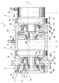
- the two-stage cross roller bearing 2 is disposed as a multistage cross roller bearing at the front end along the axis 1a of the concentric two-axis actuator 1 and the front stage actuator 3 is coaxially connected to the rear side and coaxial at the rear side.
- the rear stage actuator 4 is connected to the
- the front-stage actuator 3 includes a front-stage hollow portion 5 of a circular cross section extending through the center thereof in the direction of the axis 1a, and the rear-stage actuator 4 coaxially extends through the front-stage hollow portion 5 and extends forward And a hollow rear stage rotary output shaft 6.
- the rear stage actuator 4 of the present embodiment is provided with a rear stage hollow portion 7 of a circular cross section extending through the center in the direction of the axis 1a.
- the two-stage cross roller bearing 2 located at the front end of the concentric two-axis actuator 1 comprises an outer ring 11, an intermediate ring 12 concentrically arranged inside this, and an inner ring concentrically arranged inside this It is equipped with thirteen.
- An annular outer race 14 having a rectangular cross section is formed between the outer race 11 and the middle race 12, and a plurality of outer rollers 15 can roll on the outer races 14 with the central axes alternately orthogonal to each other. It is inserted in the state of.
- an annular inner race 16 having a rectangular cross section is formed between the middle wheel 12 and the inner ring 13, and a plurality of inner rollers 17 are inserted here with the central axes alternately orthogonal to each other. It is done.
- the outer cross roller bearing is constituted by the outer ring 11, the middle ring 12, the outer raceway 14 and the outer roller 15, and the inner cross roller bearing is constituted by the middle ring 12, the inner race 13, the inner race 16 and the inner roller 17. It is done.
- the middle wheel 12 of the two-step cross roller bearing functions as a front stage rotation output member rotationally driven by the front stage actuator 3, and the inner ring 13 functions as a rear stage rotation output member rotationally driven by the rear stage rotation output shaft 6. Further, a hollow portion extending in the direction of the axis 1 a is formed in the concentric biaxial actuator 1 by the central through hole of the inner ring 13, the hollow portion of the rear rotation output shaft 6, and the rear hollow portion 7. .
- the front stage actuator 3 includes a front stage motor 31 and a front stage wave gear reducer 32 that decelerates the output rotation of the front stage motor 31 and transmits the rotation to the outer ring 11.
- the front wave gear reducer 32 is provided with a cylindrical front speed reducer housing 34 connected to the front end side of the motor housing 43 of the front end actuator 3, and the inner peripheral side portion is coaxial with the front end rigidity.
- the internal gear 35 is fastened and fixed.
- a silk hat-shaped front stage flexible external gear 36 is coaxially disposed on the inner side, and a front stage wave generator 37 is coaxially fitted on the inner side.
- the front stage flexible external gear 36 extends radially outward from the radially deflectable cylindrical body portion 36a and the end of the cylindrical body portion 36a on the side of the two-step cross roller bearing 2
- a diaphragm 36b and a rigid annular boss 36c formed on the outer peripheral edge are provided.
- An external tooth 36d is formed on the outer peripheral surface portion of the open end on the opposite side of the cylindrical body 36a, and an outer-front wave generator having an elliptical contour is formed inside the cylindrical body 36a on which the external teeth 36d are formed. 37 are fitted, whereby the portions of the external teeth 36d located at both ends in the longitudinal direction of the elliptically deformed external toothed portion mesh with the portions of the internal teeth 35d of the front stage rigid internal gear 35.
- the outer ring 11 of the two-stage cross roller bearing 2 is fastened and fixed to the front end surface of the front stage reduction gear housing 34.
- An annular boss 36 c of the front stage flexible external gear 36 is fastened and fixed to an annular end face of the middle wheel 12 of the two-stage cross roller bearing 2.
- the front stage wave generator 37 is provided with a central through hole 37a, through which a hollow motor shaft 31a of the front stage motor 31 extends forward.
- a front stage wave generator 37 is fastened and fixed to the outer periphery of the hollow motor shaft 31a.
- both gears 35, 36 is moved in the circumferential direction by the front wave generator 37 rotated at high speed by the hollow motor shaft 31a of the front motor 31, thereby causing relative rotation due to the difference in the number of teeth of both gears. Occurs between the two gears 35, 36. Since the front stage rigid internal gear 35 is fixed so as not to rotate, the decelerating rotation that has been greatly decelerated from the front stage flexible external gear 36 is taken out and output from the middle wheel 12 connected thereto. Ru.
- the rear stage actuator 4 includes a rear stage motor 41 and a rear stage wave gear reducer 42 that decelerates the output rotation of the rear stage motor 41 and transmits it to the inner ring 13 via the rear stage rotation output shaft 6.
- the rear wave gear reducer 42 is provided with a cylindrical rear reducer housing 44 which forms a portion on the front end side of the motor housing 43 of the rear stage actuator 4, and the portion on the inner peripheral side is coaxial
- the rear rigid internal gear 45 is fastened and fixed.
- a silk hat-shaped second-stage flexible external gear 46 is coaxially disposed in the inner side, and a second-stage wave generator 47 is coaxially fitted in the second stage.
- the second-stage flexible external gear 46 has the same configuration as the first-stage flexible external gear 36, and has a cylindrical body 46a that can be bent in the radial direction, and a side of the first-stage actuator 3 in the cylindrical body 46a. It comprises a diaphragm 46b extending radially outward from the end and a rigid annular boss 46c formed on the outer peripheral edge.
- An outer tooth 46d is formed on the outer peripheral surface portion of the open end on the opposite side of the cylindrical body 46a, and an outer contour wave generator having an elliptical outline inside the cylindrical body 46a on which the outer teeth 46d are formed.
- the portions 47 of the external teeth 46 d located at both ends in the longitudinal direction of the elliptically deformed external teeth forming portion are engaged with the portions of the internal teeth 45 d of the rear rigid internal gear 45.
- the front end surface of the rear reduction gear housing 44 is fastened and fixed to the rear end surface of the cylindrical housing 33 of the front stage actuator 3.
- a connecting disc 48 provided with a central through hole 48a is disposed inside of these fastening and fixing portions.
- An annular flange 48b projecting forward is formed at a central portion of the connecting disk 48, and a central through hole of the rear end plate portion 33a of the cylindrical housing 33 of the front stage actuator 3 is formed at the front end.
- the rear end portion of the rear stage rotation output shaft 6 protruding rearward from the rear end is fastened and fixed.
- the connecting disk 48 is rotatably supported by the rear end plate portion 33 a of the cylindrical housing 33 via the ball bearing 49.
- an annular boss 46 c of the rear stage flexible external gear 46 is fastened and fixed to the end face on the rear end side of the connection disk 48.
- the rear stage wave generator 47 is provided with a central through hole 47a, and a hollow motor shaft 41a of the rear stage motor 41 extends forward through this.
- the rear stage wave generator 47 is fastened and fixed to the outer periphery of the hollow motor shaft 41a. Therefore, the mesh position of the gears 45 and 46 is moved in the circumferential direction by the rear wave generator 47 which is rotated at high speed by the hollow motor shaft 41a of the rear motor 41, thereby causing relative rotation due to the difference in the number of teeth of both gears. Occurs between the two gear wheels 45, 46.
- the inner ring of the outer cross roller bearing and the middle ring functioning as the outer ring of the inner cross roller bearing are subjected to pre-load deformation.
- the two-stage cross roller bearing 2 of this example is configured as described below, such a problem can be solved.
- the roller size of the inner cross roller bearing portion that is, the size of the inner roller 17 is the roller size of the outer cross roller bearing portion, that is, the outer roller 15 Smaller than the size.
- the roller center L2 of the inner roller 17 is offset from the roller center L1 of the outer roller 15 in the direction along the axis 1a.
- the roller size of the small-diameter inner cross roller bearing portion is small, and the roller size of the large-diameter outer cross roller bearing portion is large.
- the roller center L1 of the outer cross roller bearing and the roller center L2 of the inner cross roller bearing are offset in the direction of the axis 1a, they are positioned in the same plane in the radial direction Thus, it is possible to reduce the preload deformation occurring in the middle wheel 12.
- the offset amount ⁇ of the roller center L2 of the inner roller 17 with respect to the roller center L1 of the outer roller 15 is a half of the track width w (16) of the inner track 16 and the track width w (16) and the outer track It is desirable to set the value within a range of up to 1/2 of the added value of the orbital width w (14) of 14. If the offset amount is smaller than the value in this range, the preload deformation of the intermediate wheel can not be sufficiently suppressed, and there is a possibility that the smooth rotation of the cross roller bearing can not be secured.
- the offset deformation can not further improve the preload deformation suppressing effect of the middle wheel, and the width dimension in the direction of the central axis of the two-stage cross roller bearing Is undesirable for flattening of the two-stage cross roller bearing.
- the offset amount ⁇ is half the raceway width w (14) of the outer race 14 in order to make the two-stage cross roller bearing 2 flat while effectively suppressing the preload deformation of the middle wheel 12.
- the roller center L2 is offset from the roller center L1 toward the annular end surface 12a.
- the radial thickness t (12) between the circular inner peripheral surface 12d and the circular outer peripheral surface 12e of the middle wheel 12 is It is set to be twice or more the thickness t (11) in the radial direction from the circular inner peripheral surface 11d of the outer ring 11 to the circular outer peripheral surface 11e.
- the inner annular end faces of the outer ring 11, the middle ring 12 and the inner ring 13 are located substantially on the same plane, and the outer raceway 14 is closer to the inner end face of the outer ring 11 and the middle ring 12
- the inner raceway 16 is also on the side closer to the inner end face of the middle wheel 12 and the inner ring 13.
- insertion holes 12 f and 13 f for roller insertion are formed, and these are sealed by the plugs 18 and 19.
- the outer raceway 14 and the inner raceway 16 are brought closer to the end surface on the roller insertion side in the direction of the bearing central axis 1a. Therefore, the assemblability of the two-stage cross roller bearing 2 can be improved.
- the above example is an application of the present invention to a concentric two-axis actuator, but the present invention relates to a concentric multi-axis actuator in which the actuators are connected in tandem in three or more stages and output rotation of each stage from the same side. Is equally applicable.
- a three-stage cross roller bearing may be disposed at the front end, and a front stage actuator, a middle stage actuator and a rear stage actuator may be coaxially connected on the rear side. .
- the concentric three-axis actuator 51 includes a three-stage cross roller bearing 52, a front stage actuator 53 coaxially disposed on the rear side of the three-stage cross roller bearing 52, and a rear side of the front stage actuator 53. , And a rear stage actuator 55 coaxially disposed on the rear side of the middle stage actuator.
- the pre-stage actuator 53 is provided with a pre-stage hollow portion 56 extending through the center thereof in the direction of the axis 51a.
- the middle stage actuator 54 also has a middle stage hollow portion 57 extending through the center thereof in the direction of the axis 51a. From the middle stage actuator 54, a hollow type middle stage rotational output is made forward through the front stage hollow portion 56.
- An axis 58 extends.
- the rear stage actuator 55 is provided with a rear stage rotation output shaft 59.
- the rear stage rotation output shaft 59 extends forward through the hollow portion of the middle stage hollow portion 57 and the hollow portion of the middle stage rotation output shaft 58.
- the three-stage cross roller bearing 52 includes an outer ring 61, a first intermediate ring 62 disposed concentrically on the inner side, and a second intermediate ring 63 disposed concentrically on the inner side, concentrically disposed on the inner side
- the inner ring 64 is disposed in the state.
- an annular outer race 65 having a rectangular cross section is formed between the outer race 61 and the first middle race 62, and in the outer race 65, the central axes are alternately orthogonal in a rollable state.
- a plurality of outer rollers 66 are inserted.
- An annular intermediate orbit 67 having a rectangular cross section is also formed between the first and second intermediate wheels 62 and 63, and a plurality of annular intermediate orbits 67 are formed here in a state in which central axes alternate alternately in a rollable state.
- An intermediate roller 68 is inserted.
- an annular inner race 69 having a rectangular cross section is formed between the second middle wheel 63 and the inner ring 64, and a plurality of the inner races 69 are alternately arranged such that the central axes are alternately orthogonal in a rollable state.
- Inner roller 70 is inserted.
- the first middle wheel 62 is a front-stage rotation output member rotationally driven by the front-stage actuator 53
- the second middle wheel 63 is a middle-stage rotation output member fixedly connected to the middle-stage rotation output shaft 58. It is a rear stage rotation output member connected and fixed to the output shaft 59.
- the pre-stage actuator 53 may have the same configuration as that of the pre-stage actuator 3 of FIG. 1, and the middle-stage actuator 54 may have the same configuration as that of the post-stage actuator 4 of FIG. 1. Further, the post-stage actuator 55 may be configured such that the motor shaft 41a is a solid axis in the post-stage actuator 4 of FIG. 1 and the post-stage hollow portion 7 is omitted.
- the rear stage actuator 55 may be of the hollow type similar to the rear stage actuator 4 of FIG. 1 and the rear stage rotation output shaft 59 may be a hollow shaft. In this way, a hollow portion penetrating the center of the concentric three-axis actuator 51 is formed, so that it can be used as a wire routing portion or the like.
Landscapes
- Engineering & Computer Science (AREA)
- General Engineering & Computer Science (AREA)
- Mechanical Engineering (AREA)
- Power Engineering (AREA)
- Rolling Contact Bearings (AREA)
- Retarders (AREA)
- Connection Of Motors, Electrical Generators, Mechanical Devices, And The Like (AREA)
Abstract
Description
多段クロスローラベアリングと、前記多段クロスローラベアリングの後側に同軸状態に配置した前段アクチュエータと、前記前段アクチュエータの後側に同軸状態に配置した後段アクチュエータとを有し、
前記前段アクチュエータはその中心を軸線方向に貫通して延びている前段中空部を備え、
前記後段アクチュエータは、前記前段中空部を貫通して前方に延びている後段回転出力軸を備え、
前記多段クロスローラベアリングは、外輪と、この内側に同心状態に配置されている中間輪と、この内側に同心状態に配置されている内輪と、前記外輪および前記中間輪の間に形成した矩形断面をした円環状の外側軌道と、この外側軌道内に転動自在の状態で挿入されている複数個の外側ローラと、前記中間輪および前記内輪の間に形成した矩形断面をした円環状の内側軌道と、この内側軌道内に転動自在の状態で挿入されている複数個の内側ローラとを備え、
前記中間輪は前記前段アクチュエータによって回転駆動される前段回転出力部材であり、
前記内輪は前記後段回転出力軸に連結固定された後段回転出力部材であることを特徴としている。
前記内側ローラのローラサイズが前記外側ローラのローラサイズよりも小さく、
前記内側ローラのローラ中心が、前記外側ローラのローラ中心に対して、前記軸線に沿った方向にオフセットした位置にあることを特徴としている。
w(16)/2<Δ<{w(16)+w(14)}/2
上記の例は本発明を同心2軸アクチュエータに適用したものであるが、本発明は、アクチュエータを3段以上にタンデムに連結して、同一側から各段の回転を出力する同心多軸アクチュエータにも同様に適用できる。例えば、図3に示すように、同心3軸アクチュエータの場合には、3段クロスローラベアリングを前端に配置し、この後側に、前段アクチェエータ、中段アクチュエータおよび後段アクチュエータを同軸状態に連結すればよい。
Claims (9)
- 多段クロスローラベアリング(2)と、前記多段クロスローラベアリング(2)の後側に同軸状態に配置した前段アクチュエータ(3)と、前記前段アクチュエータ(3)の後側に同軸状態に配置した後段アクチュエータ(4)とを有し、
前記前段アクチュエータ(3)はその中心を軸線(1a)の方向に貫通して延びている前段中空部(5)を備え、
前記後段アクチュエータ(4)は、前記前段中空部(5)を貫通して前方に延びている後段回転出力軸(6)を備え、
前記多段クロスローラベアリング(2)は、外輪(11)と、この内側に同心状態に配置されている中間輪(12)と、この内側に同心状態に配置されている内輪(13)と、前記外輪(11)および前記中間輪(12)の間に形成した矩形断面をした円環状の外側軌道(14)と、この外側軌道(14)内に転動自在の状態で挿入されている複数個の外側ローラ(15)と、前記中間輪(12)および前記内輪(13)の間に形成した矩形断面をした円環状の内側軌道(16)と、この内側軌道(16)内に転動自在の状態で挿入されている複数個の内側ローラ(17)とを備え、
前記中間輪(12)は前記前段アクチュエータ(3)によって回転駆動される前段回転出力部材であり、
前記内輪(13)は前記後段回転出力軸(6)に連結固定された後段回転出力部材であることを特徴とする同心多軸アクチュエータ(1)。 - 請求項1において、
前記後段アクチュエータ(4)はその中心を軸線方向に貫通して延びている後段中空部(7)を備えており、前記後段回転出力軸(6)は中空軸であり、前記内輪(13)には中心貫通孔が形成されており、
前記後段中空部(7)、前記後段回転出力軸(6)の中空部および前記内輪(13)の中心貫通孔によって、軸線(1a)の方向に貫通して延びる中空部が形成されていることを特徴とする同心多軸アクチュエータ(1)。 - 請求項2において、
前記前段アクチュエータ(3)は前段モータ(31)と前段波動歯車減速機(32)を備え、
前記前段波動歯車減速機(32)は、前段減速機ハウジング(34)と、この内側に同軸状態に固定した前段剛性内歯歯車(35)と、この内側に同軸状態に配置されているシルクハット形状の前段可撓性外歯歯車(36)と、この内側に嵌め込まれている前段波動発生器(37)とを備え、当該前段波動発生器(37)には中心貫通孔(37a)が形成されており、
前記前段減速機ハウジング(34)には前記外輪(11)が固定され、前記前段可撓性外歯歯車(36)は前記中間輪(12)に固定され、前記前段波動発生器(37)は当該前段波動発生器の前記中心貫通孔(37a)を貫通して延びている前記前段モータ(31)の中空モータ軸(31a)に固定されており、
前記後段アクチュエータ(4)は、後段モータ(41)と後段波動歯車減速機(42)を備え、
前記後段波動歯車減速機(42)は、後段減速機ハウジング(44)と、この内側に同軸状態に固定した後段剛性内歯歯車(45)と、この内側に同軸状態に配置されているシルクハット形状の後段可撓性外歯歯車(46)と、この内側に嵌め込まれている後段波動発生器(47)とを備え、当該後段波動発生器(47)には中心貫通孔(47a)が形成されており、
前記後段減速機ハウジング(44)は前記前段モータ(31)のモータハウジング(43)に固定され、前記後段可撓性外歯歯車(46)は前記後段回転出力軸(6)の後端に固定され、前記後段波動発生器(47)は当該後段波動発生器の前記中心貫通孔(47a)を貫通して延びている前記後段モータ(41)のモータ軸(41a)に固定されていることを特徴とする同心多軸アクチュエータ(1)。 - 請求項3において、
前記内側ローラ(17)のローラサイズは、前記外側ローラ(15)のローラサイズよりも小さく、
前記内側ローラ(17)のローラ中心(L2)は、前記外側ローラ(15)のローラ中心(L1)に対して、前記軸線(1a)に沿った方向にオフセットした位置にあることを特徴とする同心多軸アクチュエータ(1)。 - 請求項4において、
前記内側ローラ(17)のローラ中心(L2)の前記外側ローラ(15)のローラ中心(L1)に対するオフセット量(Δ)は、前記内側軌道(16)の軌道幅の1/2から、当該軌道幅と前記外側軌道(14)の軌道幅との加算値の1/2までの範囲内の値であることを特徴とする同心多軸アクチュエータ(1)。 - 請求項5において、
前記オフセット量(Δ)は、前記外側軌道(14)の軌道幅の1/2であることを特徴とする同心多軸アクチュエータ(1)。 - 請求項4において、
前記中間輪(12)における円形内周面から円形外周面までの間の半径方向の厚さは、少なくとも、前記外輪(11)の円形内周面から円形外周面までの間の半径方向の厚さの2倍であることを特徴とする同心多軸アクチュエータ(1)。 - 請求項4ないし7のうちのいずれかの項において、
前記外側軌道(14)および前記内側軌道(16)は、前記外輪(11)、前記中間輪(12)および前記内輪(13)において、それらの一方の端面に近い位置に形成されており、
前記中間輪(12)および前記内輪(13)における前記端面には、それぞれ、ローラ挿入用の挿入孔(12f、13f)が形成され、これらの挿入孔が栓(18、19)によって封鎖されていることを特徴とする同心多軸アクチュエータ(1)。 - 請求項1において、
前記前段アクチュエータ(53)と前記後段アクチュエータ(55)の間には同軸状態で中段アクチュエータ(54)が配置され、
前記中段アクチュエータ(54)はその中心を軸線方向に貫通して延びている中段中空部(57)と、前記前段中空部(56)を貫通して前方に延びている中空型の中段回転出力軸(58)とを備え、
前記後段アクチュエータ(55)の前記後段回転出力軸(59)は、前記中段中空部(57)、前記中段回転出力軸(58)の中空部を貫通して前方に延びており、
前記多段クロスローラベアリング(52)は、前記中間輪として、第1中間輪(62)と、この内側に同心状に配置した第2中間輪(63)を備え、前記第1中間輪(62)と前記第2中間輪(63)の間には矩形断面をした円環状の中間軌道(67)が形成され、当該中間軌道には転動自在の状態で複数個の中間ローラ(68)が挿入されており、
前記第1中間輪(62)は前記前段アクチュエータ(53)によって回転駆動される前段回転出力部材であり、
前記第2中間輪(63)は前記中段回転出力軸(58)に連結固定された中段回転出力部材であることを特徴とする同心多軸アクチュエータ(51)。
Priority Applications (7)
| Application Number | Priority Date | Filing Date | Title |
|---|---|---|---|
| DE112011105258.8T DE112011105258B4 (de) | 2011-05-16 | 2011-05-16 | Konzentrischer mehrachsiger Aktuator |
| JP2013514850A JP5694524B2 (ja) | 2011-05-16 | 2011-05-16 | 同心多軸アクチュエータ |
| CN201180070878.7A CN103534906B (zh) | 2011-05-16 | 2011-05-16 | 同心多轴致动器 |
| US14/113,015 US9057429B2 (en) | 2011-05-16 | 2011-05-16 | Concentric multi-axis actuator |
| KR1020137032196A KR101611586B1 (ko) | 2011-05-16 | 2011-05-16 | 동심 다축 액추에이터 |
| PCT/JP2011/002718 WO2012157020A1 (ja) | 2011-05-16 | 2011-05-16 | 同心多軸アクチュエータ |
| TW100124454A TWI540031B (zh) | 2011-05-16 | 2011-07-11 | Concentric multi-axis actuator |
Applications Claiming Priority (1)
| Application Number | Priority Date | Filing Date | Title |
|---|---|---|---|
| PCT/JP2011/002718 WO2012157020A1 (ja) | 2011-05-16 | 2011-05-16 | 同心多軸アクチュエータ |
Publications (1)
| Publication Number | Publication Date |
|---|---|
| WO2012157020A1 true WO2012157020A1 (ja) | 2012-11-22 |
Family
ID=47176391
Family Applications (1)
| Application Number | Title | Priority Date | Filing Date |
|---|---|---|---|
| PCT/JP2011/002718 Ceased WO2012157020A1 (ja) | 2011-05-16 | 2011-05-16 | 同心多軸アクチュエータ |
Country Status (7)
| Country | Link |
|---|---|
| US (1) | US9057429B2 (ja) |
| JP (1) | JP5694524B2 (ja) |
| KR (1) | KR101611586B1 (ja) |
| CN (1) | CN103534906B (ja) |
| DE (1) | DE112011105258B4 (ja) |
| TW (1) | TWI540031B (ja) |
| WO (1) | WO2012157020A1 (ja) |
Cited By (3)
| Publication number | Priority date | Publication date | Assignee | Title |
|---|---|---|---|---|
| JP2018019521A (ja) * | 2016-07-28 | 2018-02-01 | ナブテスコ株式会社 | ギア装置 |
| KR20180091086A (ko) | 2016-02-02 | 2018-08-14 | 가부시키가이샤 하모닉 드라이브 시스템즈 | 파동기어장치 및 액추에이터 |
| KR102931364B1 (ko) * | 2024-05-21 | 2026-02-27 | 주식회사 아이엠에르텍 | 마그네틱 감속기와 결합된 부하측 커플러 |
Families Citing this family (12)
| Publication number | Priority date | Publication date | Assignee | Title |
|---|---|---|---|---|
| FR3022310B1 (fr) * | 2014-06-11 | 2017-03-17 | Ntn-Snr Roulements | Roulement a deux rangees concentriques de corps roulants et procede de fabrication d'un roulement. |
| DE102016217055B4 (de) * | 2015-09-10 | 2023-08-24 | Schaeffler Technologies AG & Co. KG | Getriebe mit elastischem Zahnrad |
| KR101981090B1 (ko) * | 2015-11-10 | 2019-05-22 | 가부시키가이샤 하모닉 드라이브 시스템즈 | 미끄럼 베어링 |
| JP6490243B2 (ja) * | 2015-12-21 | 2019-03-27 | 株式会社ハーモニック・ドライブ・システムズ | クロスローラベアリング |
| EP3456996B1 (en) * | 2016-05-11 | 2021-01-06 | Harmonic Drive Systems Inc. | Rotary actuator provided with wave reduction gear |
| KR102479563B1 (ko) | 2017-07-24 | 2022-12-20 | 삼성전자주식회사 | 운동 보조 장치 |
| CN107363825B (zh) * | 2017-08-25 | 2020-07-07 | 安徽大学 | 一种基于谐波减速的欠驱动2r机械臂装置 |
| DE102020204915A1 (de) | 2020-04-17 | 2021-10-21 | Zf Friedrichshafen Ag | Aktuator für Luftfahrtanwendungen |
| WO2022031238A1 (en) * | 2020-08-07 | 2022-02-10 | Spinbotics S. R. O. | Modular rotary intelligent drive |
| USD1107084S1 (en) * | 2021-09-27 | 2025-12-23 | Cloudminds Robotics Co., Ltd. | Actuator |
| USD1107083S1 (en) * | 2021-09-27 | 2025-12-23 | Cloudminds Robotics Co., Ltd. | Actuator |
| USD1107086S1 (en) * | 2021-09-27 | 2025-12-23 | Cloudminds Robotics Co., Ltd. | Actuator |
Citations (2)
| Publication number | Priority date | Publication date | Assignee | Title |
|---|---|---|---|---|
| JPH06791A (ja) * | 1992-06-19 | 1994-01-11 | Tokico Ltd | ロボットの手首機構 |
| WO2003050428A1 (en) * | 2001-12-11 | 2003-06-19 | Harmonic Drive Systems Inc. | Multi-stage cross roller bearing |
Family Cites Families (15)
| Publication number | Priority date | Publication date | Assignee | Title |
|---|---|---|---|---|
| CH651899A5 (de) * | 1979-11-02 | 1985-10-15 | Zahnradfabrik Friedrichshafen | Antrieb mit einem motor und einem spannungswellen-getriebe. |
| DE3627745A1 (de) * | 1985-08-20 | 1987-03-05 | Tokico Ltd | Industriewiedergaberoboter |
| JPS637285A (ja) * | 1986-06-26 | 1988-01-13 | 株式会社東芝 | 産業用ロボツト |
| US4929146A (en) * | 1987-11-13 | 1990-05-29 | U.S. Philips Corporation | Manipulator |
| JP2750771B2 (ja) * | 1990-03-28 | 1998-05-13 | 日本真空技術株式会社 | 多関節搬送装置 |
| JP2969981B2 (ja) * | 1991-02-07 | 1999-11-02 | 横河電機株式会社 | 2軸出力モジュール及びこれを用いた駆動装置 |
| US5222409A (en) * | 1991-09-25 | 1993-06-29 | Dalakian Sergei V | Industrial robot arms |
| JPH05329785A (ja) * | 1992-05-27 | 1993-12-14 | Yokogawa Electric Corp | 駆動装置 |
| KR100303018B1 (ko) * | 1993-04-16 | 2001-11-22 | 스탠리 디. 피에코스 | 관절형아암이송장치 |
| US5816117A (en) * | 1997-03-19 | 1998-10-06 | Teijiu Seiki Co., Ltd. | Dual inputs and dual outputs harmonic drive apparatus |
| US6485250B2 (en) * | 1998-12-30 | 2002-11-26 | Brooks Automation Inc. | Substrate transport apparatus with multiple arms on a common axis of rotation |
| JP4148280B2 (ja) * | 2005-10-18 | 2008-09-10 | セイコーエプソン株式会社 | 平行リンク機構及び産業用ロボット |
| JP4737695B2 (ja) * | 2005-12-20 | 2011-08-03 | 株式会社ハーモニック・ドライブ・システムズ | 指関節機構 |
| US8291788B2 (en) * | 2009-09-22 | 2012-10-23 | GM Global Technology Operations LLC | Rotary series elastic actuator |
| JP5697356B2 (ja) * | 2010-04-06 | 2015-04-08 | キヤノン株式会社 | 波動歯車装置及びロボットアーム |
-
2011
- 2011-05-16 JP JP2013514850A patent/JP5694524B2/ja active Active
- 2011-05-16 US US14/113,015 patent/US9057429B2/en active Active
- 2011-05-16 KR KR1020137032196A patent/KR101611586B1/ko active Active
- 2011-05-16 CN CN201180070878.7A patent/CN103534906B/zh active Active
- 2011-05-16 WO PCT/JP2011/002718 patent/WO2012157020A1/ja not_active Ceased
- 2011-05-16 DE DE112011105258.8T patent/DE112011105258B4/de active Active
- 2011-07-11 TW TW100124454A patent/TWI540031B/zh active
Patent Citations (2)
| Publication number | Priority date | Publication date | Assignee | Title |
|---|---|---|---|---|
| JPH06791A (ja) * | 1992-06-19 | 1994-01-11 | Tokico Ltd | ロボットの手首機構 |
| WO2003050428A1 (en) * | 2001-12-11 | 2003-06-19 | Harmonic Drive Systems Inc. | Multi-stage cross roller bearing |
Cited By (4)
| Publication number | Priority date | Publication date | Assignee | Title |
|---|---|---|---|---|
| KR20180091086A (ko) | 2016-02-02 | 2018-08-14 | 가부시키가이샤 하모닉 드라이브 시스템즈 | 파동기어장치 및 액추에이터 |
| US10865866B2 (en) | 2016-02-02 | 2020-12-15 | Harmonic Drive Systems Inc. | Strain wave gearing and actuator |
| JP2018019521A (ja) * | 2016-07-28 | 2018-02-01 | ナブテスコ株式会社 | ギア装置 |
| KR102931364B1 (ko) * | 2024-05-21 | 2026-02-27 | 주식회사 아이엠에르텍 | 마그네틱 감속기와 결합된 부하측 커플러 |
Also Published As
| Publication number | Publication date |
|---|---|
| DE112011105258T5 (de) | 2014-02-20 |
| TW201247375A (en) | 2012-12-01 |
| DE112011105258B4 (de) | 2021-06-24 |
| KR20140038980A (ko) | 2014-03-31 |
| KR101611586B1 (ko) | 2016-04-11 |
| US9057429B2 (en) | 2015-06-16 |
| JP5694524B2 (ja) | 2015-04-01 |
| CN103534906A (zh) | 2014-01-22 |
| US20140033840A1 (en) | 2014-02-06 |
| JPWO2012157020A1 (ja) | 2014-07-31 |
| TWI540031B (zh) | 2016-07-01 |
| CN103534906B (zh) | 2016-02-17 |
Similar Documents
| Publication | Publication Date | Title |
|---|---|---|
| WO2012157020A1 (ja) | 同心多軸アクチュエータ | |
| TWI550211B (zh) | An internal gear unit with a compound rolling bearing and a harmonic gear device | |
| TWI550212B (zh) | Unit type harmonic gear device | |
| JP5536341B2 (ja) | 減速装置 | |
| JP5156961B2 (ja) | 減速装置 | |
| US20160325613A1 (en) | Drive device for hybrid vehicle | |
| JP6208820B2 (ja) | 減速装置 | |
| WO2009093556A1 (ja) | 傘歯車を有する動力伝達装置 | |
| US10683910B2 (en) | Power transmission mechanism | |
| CN102242795B (zh) | 精密摆线减速器 | |
| EP2233789A1 (en) | Ball screw device | |
| JP5961214B2 (ja) | 減速装置 | |
| CN106989143B (zh) | 行星减速装置 | |
| JP4891890B2 (ja) | 最終減速装置 | |
| JP6338538B2 (ja) | 撓み噛合い式歯車装置 | |
| JP2008157351A (ja) | 減速機および車両用アクティブスタビライザー装置 | |
| JP2009222116A (ja) | 遊星歯車装置及びこれを組み込んだアクチュエータ及びロボット装置 | |
| JP5659588B2 (ja) | ホイール軸受および電動車両駆動装置 | |
| JP2023049583A (ja) | 駆動ユニット、操舵ユニットおよび運搬装置 | |
| JP2017089804A (ja) | トラクションドライブ機構を備えた波動歯車装置 | |
| JP6658461B2 (ja) | 波動歯車装置 | |
| WO2019009176A1 (ja) | 減速機 | |
| JP2007051709A (ja) | ハイポサイクロイド歯車減速装置 | |
| JP2008164020A (ja) | ピニオン軸の支持構造 |
Legal Events
| Date | Code | Title | Description |
|---|---|---|---|
| WWE | Wipo information: entry into national phase |
Ref document number: 201180070878.7 Country of ref document: CN |
|
| 121 | Ep: the epo has been informed by wipo that ep was designated in this application |
Ref document number: 11865509 Country of ref document: EP Kind code of ref document: A1 |
|
| ENP | Entry into the national phase |
Ref document number: 2013514850 Country of ref document: JP Kind code of ref document: A |
|
| WWE | Wipo information: entry into national phase |
Ref document number: 14113015 Country of ref document: US |
|
| WWE | Wipo information: entry into national phase |
Ref document number: 112011105258 Country of ref document: DE Ref document number: 1120111052588 Country of ref document: DE |
|
| ENP | Entry into the national phase |
Ref document number: 20137032196 Country of ref document: KR Kind code of ref document: A |
|
| 122 | Ep: pct application non-entry in european phase |
Ref document number: 11865509 Country of ref document: EP Kind code of ref document: A1 |