WO2012153679A1 - 電子機器 - Google Patents
電子機器 Download PDFInfo
- Publication number
- WO2012153679A1 WO2012153679A1 PCT/JP2012/061565 JP2012061565W WO2012153679A1 WO 2012153679 A1 WO2012153679 A1 WO 2012153679A1 JP 2012061565 W JP2012061565 W JP 2012061565W WO 2012153679 A1 WO2012153679 A1 WO 2012153679A1
- Authority
- WO
- WIPO (PCT)
- Prior art keywords
- cradle
- connector
- state
- door
- posture
- Prior art date
- Legal status (The legal status is an assumption and is not a legal conclusion. Google has not performed a legal analysis and makes no representation as to the accuracy of the status listed.)
- Ceased
Links
Images


Classifications
-
- H—ELECTRICITY
- H05—ELECTRIC TECHNIQUES NOT OTHERWISE PROVIDED FOR
- H05K—PRINTED CIRCUITS; CASINGS OR CONSTRUCTIONAL DETAILS OF ELECTRIC APPARATUS; MANUFACTURE OF ASSEMBLAGES OF ELECTRICAL COMPONENTS
- H05K7/00—Constructional details common to different types of electric apparatus
- H05K7/02—Arrangements of circuit components or wiring on supporting structure
- H05K7/10—Plug-in assemblages of components, e.g. IC sockets
-
- H—ELECTRICITY
- H04—ELECTRIC COMMUNICATION TECHNIQUE
- H04M—TELEPHONIC COMMUNICATION
- H04M1/00—Substation equipment, e.g. for use by subscribers
- H04M1/02—Constructional features of telephone sets
- H04M1/04—Supports for telephone transmitters or receivers
-
- G—PHYSICS
- G06—COMPUTING OR CALCULATING; COUNTING
- G06F—ELECTRIC DIGITAL DATA PROCESSING
- G06F1/00—Details not covered by groups G06F3/00 - G06F13/00 and G06F21/00
- G06F1/16—Constructional details or arrangements
- G06F1/1613—Constructional details or arrangements for portable computers
- G06F1/1632—External expansion units, e.g. docking stations
-
- H—ELECTRICITY
- H04—ELECTRIC COMMUNICATION TECHNIQUE
- H04M—TELEPHONIC COMMUNICATION
- H04M1/00—Substation equipment, e.g. for use by subscribers
- H04M1/72—Mobile telephones; Cordless telephones, i.e. devices for establishing wireless links to base stations without route selection
- H04M1/724—User interfaces specially adapted for cordless or mobile telephones
- H04M1/72403—User interfaces specially adapted for cordless or mobile telephones with means for local support of applications that increase the functionality
- H04M1/72409—User interfaces specially adapted for cordless or mobile telephones with means for local support of applications that increase the functionality by interfacing with external accessories
-
- H—ELECTRICITY
- H04—ELECTRIC COMMUNICATION TECHNIQUE
- H04M—TELEPHONIC COMMUNICATION
- H04M1/00—Substation equipment, e.g. for use by subscribers
- H04M1/72—Mobile telephones; Cordless telephones, i.e. devices for establishing wireless links to base stations without route selection
- H04M1/724—User interfaces specially adapted for cordless or mobile telephones
- H04M1/72403—User interfaces specially adapted for cordless or mobile telephones with means for local support of applications that increase the functionality
- H04M1/72442—User interfaces specially adapted for cordless or mobile telephones with means for local support of applications that increase the functionality for playing music files
Definitions
- the present invention relates to an electronic device, and more particularly to an electronic device to which a mobile terminal device can be attached.
- the portable terminal device is roughly classified into a small one that mainly plays music (for example, a portable music player having a long side of about 100 mm and a short side of about 40 mm), a display having a communication function and a diagonal of about 4 inches.
- a device having a device for example, a mobile phone called a smartphone
- a tablet device having a display device having a diagonal of about 10 inches are examples of portable terminal devices.
- These portable terminal devices have a terminal unit that performs audio or video signal exchange with the outside.
- the portable terminal device is configured to listen mainly to headphones with respect to output sound, and is not provided with a speaker or is small even if provided.
- the output image there is a limit to enlargement of the screen size because portability is important. Therefore, in order to respond to the user's request to listen to a large volume or high-quality playback sound or to enjoy an image on a larger screen, the portable terminal device can be held with a connector structure that can be connected to the terminal portion.
- Electronic devices with cradle are on sale. An example of this electronic device is described in Patent Document 1.
- an object of the present invention is to provide an electronic device that can maintain a high appearance quality without any external force being applied to the connector even when the mobile terminal device is not attached.
- the first aspect of the present invention is a case (1) having an opening (1k) in a part of the surface, and the opening (1k) is selectively turned by rotation.
- a cradle (1) having a first surface (11b) and a second surface (11a) exposed on the first surface (11b), and a door (11) having a connector (14). 15) and an electronic device (50).
- the cradle has a first posture and a second posture around a cradle rotation axis (CL15) orthogonal to the first surface (11b). It is comprised so that rotation is possible between them.
- the first surface (11b) is a surface having the same height or a protruding surface with respect to the surface (7a) surrounding the opening (1k).
- the first posture is a posture in which the entirety of the cradle (15) is within the range of the first surface (11b), and the second posture is A part of the cradle (15) projects out of the range of the first surface (11b).
- the door portion (11) rotates about a predetermined rotation axis (CL12), and the first surface (11b) and the second surface ( 11a) is set as two cut surfaces that do not intersect each other among cut surfaces obtained by cutting a right circular cylinder centering on the rotation axis (CL12) along a plane parallel to the rotation axis (CL12). .
- the first surface (11b) and the second surface (11a) have the same width in the direction orthogonal to the rotation axis (CL12).
- the door section (11) has a substantially fan-shaped cross section.
- the electronic device of the present invention there is no possibility that an external force is applied to the connector even when the portable terminal device is not attached, and an effect that the appearance quality can be maintained high can be obtained.
- An electronic apparatus is a control device 50 that includes a connector for connecting a mobile terminal device, and allows the mobile terminal to be connected to the connector.
- This control device 50 and a pair of left and right speaker systems constitute a portable terminal compatible audio system, which is sold as a single control device 50 or a portable terminal compatible audio system.
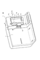
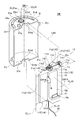
- FIG. 1 shows a basic state of the control device 50.
- the front side, the back side, the left side, the right side, the upper side, and the lower side of the control device 50 are respectively defined on the instructed side.
- the control device 50 can be broadly divided into two modes: a basic state in which the mobile terminal device cannot be mounted and a connected state in which the mobile terminal device can be mounted (details will be described later).
- the control device 50 includes a housing 1 in which a front cover 1 ⁇ / b> F and a back cover 1 ⁇ / b> R are combined to form a substantially L shape when viewed from the left, a signal processing circuit, and the like. And a circuit unit 2 housed therein.
- a front cover 1 ⁇ / b> F and a back cover 1 ⁇ / b> R are combined to form a substantially L shape when viewed from the left, a signal processing circuit, and the like.
- a circuit unit 2 housed therein.
- On the rear surface (back side of the paper in FIG. 1) HM of the housing 1 are output terminals for speaker output and video output including a subwoofer, input terminals for DC power input and antenna input, and other terminals such as a USB terminal.
- the back terminal part 4 (only a code
- the front side of the housing 1 is generally composed of three parts. Specifically, the front portion 5 has a surface M1 connected to the bottom surface BTM, which is the reference surface KM, and rises perpendicularly from the bottom surface BTM, and is connected to the surface M1 and extends substantially parallel to the bottom surface BTM toward the back surface HM. These are three parts: a shelf part 6 having a surface M2 to be connected and a dock part 7 having a surface M3 connected to the surface M2 and rising toward the upper surface TM.
- the surface M2 and the surface M3 are smoothly connected with a predetermined curvature R.
- the surface M3 may be a surface orthogonal to the reference surface KM, but it is desirable that the surface M3 be inclined in a direction approaching the back surface HM as the distance from the bottom surface BTM increases.
- the angle ⁇ a shown in FIG. 1 is set to 75 °, and the dock portion 7 is tilted slightly upward.
- An operation unit 8 including a plurality of operation buttons for operating the control device 50 is disposed in a region on the right side of the shelf 6.
- the operation buttons include power on / off, input selection, and playback content sending / returning.
- the dock part 7 is flat as a whole, but is partitioned by design so that the two parts can be divided and recognized. Specifically, a line portion 9 extending in the vertical direction with a predetermined width W1 is provided.
- the line portion 9 is a finish that can be recognized as a different portion from another portion by another member. Even if the line part 9 is not a separate member, it may be distinguished from other parts by changing the surface roughness, coating, etc. on the same member.
- the line part 9 may protrude rather than the surface of the other dock part 7, it is desirable that it is the same surface or a concave surface.
- the dock part 7 can visually recognize two areas of the left dock area DR 1 and the right dock area DR 2 on the left side with respect to the line part 9. Yes.
- the line portion 9 may be provided at the center of the dock portion 7 in the left-right direction, but is desirably provided at a position on either the left or right side. In the control apparatus 50 shown in FIG. 1, it is provided at a position biased to the right. Therefore, the left dock region DR1 has a larger area than the right dock region DR2.
- An opening 9k is formed at substantially the center of the line portion 9 in the vertical direction.
- the opening 9k is provided with a pushing portion 10 that is provided as a separate member from the line portion 9 and can be pushed with a finger.
- a latch described later
- a connector described later
- a substantially rectangular opening 1k is provided in the right dock region DR2.
- a door portion 11 made of a member having a rectangular shape and different from other portions is arranged so as to face.
- a latch (described later) is released and rotated, and another connector (described later) for mounting the mobile terminal device is exposed to the outside.
- the decorative surface 11a of the door portion 11 is exposed.
- the control device 50 can connect one mobile terminal device to each of the left dock region DR1 and the right dock region DR2.
- each mobile terminal device having a shape within a predetermined range can be held.
- the control apparatus 50 which can connect two portable terminal devices is demonstrated as an example. Since the control device 50 is provided with the line portion 9 biased to the right, the area of the left dock region DR1 is large and a portable terminal larger than the right dock region DR2 can be held. For example, a tablet-type mobile terminal can be connected and held.
- the right dock region DR2 is configured to be able to hold and favorably connect a portable terminal device such as a small portable music player or a smartphone.
- the dock portion 7 In the left dock region DR1, there are two abutting members 12 made of rubber, sponge, etc. on the dock portion 7 and two on the shelf portion 6 for preventing scratches and slipping when holding the tablet type mobile terminal. Is provided.
- the contact member 12 is provided to have a contact surface that slightly protrudes from the surface of the housing 1 so that the mobile terminal and the housing 1 do not directly contact each other.
- the dock portion 7 In the basic state shown in FIG. 1, the dock portion 7 is configured to have substantially the same flat surface including the line portion 9 and the door portion 11 except for the contact member 12.
- FIG. 2 shows the connection state of the control device 50. The transition from the reference state to the connected state will also be described with reference to FIGS.
- the pushing portion 10 In the reference state shown in FIG. 1, when the pushing portion 10 is pushed with a finger, the latch is unlocked, and the pushing portion 10 pops out so as to protrude from the surface of the dock portion 7 by a biasing force of a biasing member described later. It is like that.
- a connector 13 is integrally attached to the push-in portion 10, and the connector 13 is exposed to the outside by this protrusion. Accordingly, the connector 13 is projected and retracted with respect to the housing 1 and is housed inside the housing 1 in a normal state and exposed to the outside in a connected state. The connector 13 protrudes toward one side in an exposed state. In the control device 50, the connector 13 projects leftward.
- the portable terminal device mounted in the left dock region DR1 does not protrude rightward from the line portion 9 except when it has a special shape. That is, even if the shape and size of the mobile terminal device connected to the connector 13 is different, the mobile terminal device can be mounted on the left dock region DR1 without affecting the mounting of the right dock region DR2.
- the door portion 11 when the vicinity of the right end portion of the door portion 11 is pushed in with a finger, the door portion 11 is unlocked by a latch (not shown) and rotated, so that the cradle support surface 11b separate from the decorative surface 11a is exposed. It has become. That is, the decorative surface (second surface) 11a and the cradle support surface (first surface) 11b are selectively exposed.
- a cradle 15 integrally provided with a connector 14 to which a portable terminal device can be connected is supported so as to be rotatable about a rotation axis CL15 (described later).
- the connector 14 is projected and retracted with respect to the housing 1 and is housed inside the housing 1 in a normal state and exposed to the outside in a connected state.
- the rotation axis CL15 is set as a line perpendicular to the cradle support surface 11b.
- the cradle support surface 11b is set to be substantially the same plane as the surface of the dock portion 7. Specifically, in the right dock region DR2, the cradle support surface 11b is substantially the same plane as the surrounding surface 7a that surrounds the door portion 11 in the dock portion 7.
- connection state has been described as a state in which both the connector 13 and the connector 14 are exposed to the outside of the housing 1 for convenience.
- each of the connectors 13 and 14 is independent of the housing. The basic state hidden inside the body 1 and the connection state exposed to the outside can be taken.
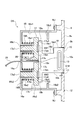
- FIG. 3 is a cross-sectional view taken along the line AA in FIG.
- the C holder 18 (described later) is not a sectional view but a plan view for easy understanding.
- a connector connecting portion CS includes a connector box (hereinafter referred to as a C box) 16 as a base body, and a slider that is housed in the C box 16 and is movable in a uniaxial direction (left and right direction in FIG. 3) 17, a connector holder (hereinafter referred to as C holder) 18 that is attracted to the slider 17 by magnetic force, a pair of coil springs 19 ⁇ / b> A and 19 ⁇ / b> B as biasing members, and a latch device 20.
- a connector box hereinafter referred to as a C box
- C holder connector holder
- the C box 16 is formed in a generally box shape with the right side in FIG. 3 open.
- the C box 16 is made of a resin material.
- An example of the material is ABS (acrylonitrile butadiene styrene) resin.
- a pair of cylindrical portions 16a1 and 16a2 are formed on the bottom surface 16a of the C box 16 so as to be spaced apart in the vertical direction in FIG.
- through holes 16k1 and 16k2 are formed in the respective cylindrical portions 16a1 and 16a2.
- a penetrating opening 16c is formed in a portion between the pair of cylindrical portions 16a1 and 16a2 on the bottom surface 16a, and the latch device 20 is attached.
- the open end side of the C box 16 is fastened to the back side of the line portion 9 by a male screw NJ.
- Ribs 16b1 and 16b2 projecting so as to approach the opposed inner side surfaces 16s2 and 16s1 are formed at portions close to the open ends of the pair of inner side surfaces 16s1 and 16s2 of the C box 16.
- the slider 17 has a flat plate-like base portion 17k and a pair of bosses 17a1 and 17a2 provided on the back side surface 17kr of the base portion 17k (left side surface in FIG. 3) so as to be vertically separated. Yes.
- the slider 17 is formed of a resin material, and an example of the material is ABS resin.
- On the back side surface 17kr a standing arm portion 17b and an opening portion 17c penetrating therethrough are formed in a portion between the pair of bosses 17a1 and 17a2.
- a pair of magnets 17d1 and 17d2 are embedded on the front surface 17kh side of the base portion 17k so as to be spaced apart in the vertical direction.
- a pair of dowel holes 17e1 and 17e2 are formed on both outer sides of the magnets 17d1 and 17d2 in the vertical direction.
- the C holder 18 is formed of a resin material.
- An example of the material is ABS resin.
- the C holder 18 has a substantially flat base portion 18k extending in a direction along the plane of FIG. 3, a planar push-in portion 10 extending perpendicularly from one end edge of the base portion 18k, and one end side of the base portion 18k.
- a connector 13 provided so as to project substantially in parallel with the push-in portion 10 and three flange portions 18a to 18c extending from the other end edge of the base portion 18k upward, downward, and toward the front side of FIG. And are formed.
- the base portion 18k is formed with a notch portion 18d in which a predetermined range is missing in a rectangular shape from the other end edge side to the one end side.
- An end 18d1 on one end side of the notch 18d is located at a distance D18 from the outer surface 10s of the push-in portion 10.
- the flange portion 18a and the flange portion 18b protrude from the base portion 18k and are connected also on the back side in FIG.
- the other end sides of the flange portions 18a to 18c and the base portion 18k are flat end surfaces 18kt, and a pair of magnetic bodies 18f1 and 18f2 are embedded in the end surfaces 18kt so as to be separated in the vertical direction.
- An example of the magnetic material is an iron plate.
- a pair of dowels 18e1 and 18e2 are formed on both outer sides in the vertical direction of the pair of magnetic bodies 18f1 and 18f2.
- An opening path that communicates from the opening 18g (see FIG. 6) provided on the other end face of the base 18k to the connector 13 is formed inside the C holder 18, and one end is connected to the connector 13.
- the cable 21 is pulled out through the opening 18g.
- the other end side of the cable 21 is connected to the circuit unit 2.
- the coil springs 19A and 19B are extrapolated into the cylindrical portions 16a1 and 16a2, respectively, one end side is in contact with the bottom surface 16a, the other end side is in contact with the back side surface 17kr of the base portion 17k of the slider 17, and both ends are in contact with each other.
- the dimensions are set so that they are always compressed in the state.
- a pair of bosses 17a1 and 17a2 of the slider 17 are inserted into the pair of through holes 16k1 and 16k2 in the cylindrical portions 16a1 and 16a2 of the C box 16, respectively. It is possible to move in the direction.
- the arm portion 17 b of the slider 17 is engaged with the latch device 20.
- the latch device 20 holds the arm portion 17b by engaging with the tip of the arm portion 17b when the L-shaped arm portion 17b is pushed from right to left.
- the engagement is released and the arm portion 17b is released. Therefore, in the basic state shown in FIG. 3, the arm portion 17b is engaged with and held by the latch device 20, and the slider 17 is prohibited from moving in the right direction in FIG.
- the magnets 17d1, 17d2 provided on the slider 17 and the pair of magnetic bodies 18f1, 18f2 of the C holder 18 are provided at positions corresponding to each other. The two are attracted to each other by magnetic force so that the front side surface 17 kh of the base portion 17 k of the slider 17 and the end surface 18 kt of the C holder 18 come into contact with each other. Further, in this basic state, the outer surface 10s of the push-in portion 10 is dimensioned and the like so as to be included in the same plane with no step difference from the outer surface 9s of the line portion 9.
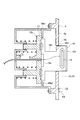
- FIG. 4 shows a state where this movement is restricted.
- this state is referred to as a pop-up state (PU state).
- PU state the notch 18d of the C holder 18 is not exposed to the outside from the opening 9k.
- the end portion 18d1 on the connector 13 side of the cutout portion 18d is located on the inner side of the outer surface 9s.
- the distance H2 between the apex of the abutting member 12 and the central axis CL13 of the connector 13 is the most frequently mounted among the mobile terminal devices that can be connected to the connector 13 and can be held in the left dock region DR1.
- the position of the connector 13 in the vertical direction is also set so that the lower surface of the device that is considered to be the most frequently attached comes into contact with the abutting member 12 of the shelf 6. Therefore, the connector 13 can be easily attached to the connector of the mobile terminal device by placing the C holder 18 in the PU state and sliding the mobile terminal device to be attached against the abutting member 12.
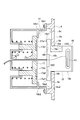
- FIG. 5 shows a state where, in this free state, the C holder 18 is located slightly on the inner side from the state moved to the right in FIG. 4 so as to be most exposed to the outside.
- the most exposed state is referred to as the most protruding state.
- the most projecting state (including the PU state) with respect to FIG. 5 is a state in which the right side surface of the flange portions 18 a to 18 c of the C holder 18 is in contact with the inner side surface 9 n of the line 9.
- a space V1 that is substantially surrounded by the inner side surfaces 16s1, 16s2, and the inner side surface 9n of the line 9 is formed.
- the C holder 18 has a shape of each of the flanges 18a to 18c and the shape of the opening 9k so that the slider 17 does not move outward from the opening 9k of the line portion 9 at least in a free state where the slider 17 is in contact with the ribs 16b1 and 16b2. Opening dimensions are set.
- the C holder 18 can freely take any posture as long as the collar portions 18a to 18c are in the space V1. That is, the front surface 17 kh of the slider 17, the ribs 16 b 1 and 16 b 2, the inner surfaces 16 s 1 and 16 s 2 of the C box 16 and the inner surface 9 n of the line 9 have positions and postures that the C holder 18 in a free state can take within a predetermined range. It functions as a regulation section that regulates spatially. Further, since the notch 18d is formed, a gap is generated by a distance H18 in the vertical direction with respect to the opening 9k. Therefore, the position of the connector 13 can be moved in the vertical direction by the distance H18. As a result, the possible range of the position and orientation of the C holder 18 is further expanded, and it is easier to attach the connector 13 to the mobile terminal device to be attached to the left dock region DR1. A portable terminal device having a shape can be held.
- the C holder 18 When moving from the most protruding state to the PU state, the C holder 18 is moved to the left in FIG. As a result, the two magnets 17d1 and 17d2 and the pair of magnetic bodies 18f1 and 18f2 corresponding thereto are attracted to each other so as to be in a substantially predetermined relative position, and finally the dowel hole 17e1. , 17e2 and dowels 18e1 and 18e2 are respectively fitted, and the slider 17 and the C holder 18 are integrated while being positioned. Furthermore, the transition from the PU state to the basic state may be performed by further pressing the C holder 18 integrated with the slider 17. By this pushing, the latch device 20 holds the arm portion 17b of the slider 17 and enters a basic state.
- the outer surface 10s of the C holder 18 is flush with the surrounding surface in the basic state, and the appearance quality is improved because it is not concave or convex.
- the connector 13 In the PU state, since the connector 13 is held at a predetermined protruding position, it is very easy to connect the connector of the portable terminal device that conforms to the predetermined position.
- the C holder 18 In the free state in which the C holder 18 is separated from the slider 17, the C holder 18 can take a free posture, and the position of the connector 13 can also be freely positioned within a predetermined range of space. It is possible to connect the portable terminal device with a connector.
- a mobile terminal device having a different shape such as a mobile terminal device that is thickened by attaching a cover or the like.
- the most protruding state in which the protruding amount of the C holder 18 is regulated as a predetermined amount is set, there is no possibility that the C holder 18 protrudes more than necessary even when an unexpected external force is applied, and breakage or cable Disconnection is prevented.
- the user who picks up the C holder 18 with his / her finger can bring the C holder 18 into a desired posture while feeling the magnetic attractive force by the magnet, and the user can obtain a very good operation feeling. it can.
- FIG. 7 is an exploded perspective view illustrating the structure of the door rotation unit DK.
- the door rotation part DK engages with the door box part 31 formed in a semi-tubular shape having a substantially circular cross section, and rotates around a predetermined axis in the space inside the door box part 31.
- the door part 11 is comprised.
- the door box portion 31 has wall portions 31a and 31b formed at both ends.
- An inner peripheral surface 31c of the door box portion 31 is formed as a part of a circumferential surface centered on the central axis CL31.
- An arcuate slit 31d centered on the central axis CL31 is formed in one wall portion 31a.
- a latch device 31f is attached in the vicinity of one end of the slit 31d in the wall portion 31a, and a rib 31g is formed in the vicinity of the latch device 31f.
- the wall 31a is provided with a viscous damper 31e having a pinion 31e1 that rotates around a central axis CL31a parallel to the central axis CL31.
- the wall portions 31a and 31b are formed with notches 31ha and 31hb including arc-shaped portions 31h1 and 31h2 with the central axis CL31 as the center.
- a plurality of ribs 31j projecting outward and having through holes are provided on the open end side.
- the ribs 31j are used to fix the door rotation part DK to the front cover 1F (not shown in FIG. 7) with screws.
- the door part 11 is formed as a column having a fan-like cross section. Specifically, the door portion 11 is formed in a plane that intersects with a plane 11A having a makeup surface 11a that is planar and substantially free of unevenness, and a plane that includes the makeup surface 11a at a virtual intersection line CL11 and forms an angle ⁇ b.
- a cradle support portion 11B having a cradle support surface 11b, a peripheral surface portion 11C having an arcuate peripheral surface 11c centered on the virtual intersection line CL11, and a circle having a smaller diameter than the peripheral surface 11c centered on the virtual intersection line CL11
- the end surface portion 11D has an end surface 11d that is arcuate and faces the peripheral surface 11c, and wall surface portions 11E and 11F that have wall surfaces 11e and 11f that close both ends, respectively.
- the angle ⁇ b is, for example, 25 °.
- the cradle support portion 11B is provided with a cradle 15 that protrudes with respect to the cradle support surface 11b having a substantially flat surface.
- the cradle 15 has a substantially L-shaped side view, and has a base portion 15k that is close to and opposed to the cradle support surface 11b and a shelf portion 15t that is bent at a substantially right angle from the base portion 15k. Yes.
- a connector 14 is attached to the shelf 15t so as to protrude substantially parallel to the base 15k.
- a guide portion 16 that can enter and exit with a predetermined stroke in the direction of the arrow DR16 in FIG. 7 is provided.
- a click feeling can be obtained at predetermined intervals.
- a lock mechanism that selects prohibition and allowance of entry and exit may be provided.
- the cable 22 having one end connected to the connector 14 passes through the inside of the cradle 15 and is drawn out through a cylindrical shaft portion 11h2 described later. The other end side of the cable 22 is connected to the circuit unit 2.
- the cradle 15 is configured to rotate around a cradle rotation axis CL15 (hereinafter simply referred to as a rotation axis CL15) set on the end side opposite to the shelf 15t.
- the rotation axis CL15 is set as an axis orthogonal to the cradle support surface 11b. That is, the cradle 15 is rotatable in a plane parallel to the cradle support surface 11b in a state where the cradle support surface 11b is selectively exposed.
- the door rotation unit DK is configured to rotate about 90 ° counterclockwise (in the direction of the arrow DR15 in FIG. 7) from the posture illustrated in FIG.
- the click feeling is given at the positions of 0 ° and 90 °, and the posture is held so as to be maintained below a predetermined turning force of externally applied.
- the posture of the cradle shown in FIG. 7 is referred to as a vertical posture
- the posture rotated 90 ° is referred to as a horizontal posture.
- the cradle 15 is entirely accommodated in the cradle support surface 11b in the vertical posture.
- the cradle 15 is in a vertical posture and has a shape that does not interfere with other members when the door portion 11 rotates.
- the cradle support surface 11b is formed so as not to be recessed at least with respect to the surrounding surface 7a in order to allow the lateral posture of the cradle 15. In other words, the surface is either the same surface or the protruding surface.
- the cradle 15 is supported rotatably in a plane parallel to the cradle support surface 11b. Therefore, the cradle 15 can rotate without being restricted by the surrounding surface 7a in a state where the cradle support surface 11b is selectively exposed.
- the cradle support surface 11b is a projecting surface with respect to the surrounding surface 7a, the cradle support surface 11b and the surrounding surface 7a are parallel so as not to restrict the rotation of the cradle 15. It is preferable.
- a rotation axis CL12 is virtually set in the door portion 11, and a shaft portion 11h having the rotation axis CL12 as a central axis is formed to protrude from the wall surface 11e.
- a cylindrical shaft portion 11h2 having the rotation axis CL12 as a central axis is also formed on the wall surface 11f.
- the rotation axis CL12 is set to coincide with the center axis CL31 in the assembled state as the door rotation portion DK.
- the rotation axis CL12 is set to be the same as the inclination angle of the dock portion 7. Specifically, it is set parallel to the surrounding surface 7a. The setting position of the rotation axis CL12 in the door part 11 will be described later.
- a gear 11g is integrally formed on the shaft portion 11h.
- a boss 11j is erected on the peripheral surface portion 11C side of the wall surface 11e.
- a magnetic piece 11j1 made of a magnetic material is attached to the boss 11j.
- the boss 11j is provided with an arm portion 11n that can be locked to the latch device 31f.
- a coil portion of a torsion coil spring 11k as an urging member is fitted into the shaft portion 11h, one arm 11k1 is locked to the boss 11j, and the other arm 11k2 is in a free state.
- a flat washer 11m is screwed to the tip of the shaft portion 11h so that the torsion coil spring 11k cannot be removed.
- the door portion 11 has the boss 11j inserted through the slit 31d of the door box portion 31 from the inside (see the alternate long and short dash line LN1), the shaft portion 11h is engaged with the arc-shaped portion 31h1, and the shaft portion 11h2 is engaged with the arc-shaped portion 31h2. It is combined with the door box part 31 by engaging. In this state, the gear 11g meshes with the pinion 31e1. Further, the arm 11k2 of the torsion coil spring 11k is hooked on the rib 31g. Thereby, the door part 11 is urged
- the door rotation part DK is attached to the back side of the front cover 1F.
- the decorative surface 11a or the cradle support surface 11b of the door portion 11 faces the opening portion 1k in a state where the door rotating portion DK is attached.
- there is almost no gap between the opening 1k of the housing 1 and the surface around the opening 1k is set to be substantially the same surface with no unevenness.
- the magnetic piece 11j1 With the door 11 biased by the torsion coil spring 11k and rotated most in the direction of the arrow DR11, the magnetic piece 11j1 is in close proximity to a magnet (not shown) provided on the back surface of the housing 1 correspondingly. Or it comes to contact
- the door portion 11 when the right edge portion of the door portion 11 is pushed with a finger, the door portion 11 is counterclockwise when a force greater than the resultant force of the urging force of the torsion coil spring 11k and the magnetic force by a magnet (not shown) is applied. It rotates in the direction (opposite direction of arrow DR11).
- the angle ⁇ b is 25 °
- the surface facing the opening 1k can be switched between the decorative surface 11a and the cradle support surface 11b.
- the cross-sectional shape of the door portion 11 is formed as a column having a generally fan shape, the surface facing the opening 1k can be made by simply rotating the door portion 155 ° which is smaller than 180 °. It is possible to switch between the surface 11a and the cradle support surface 11b.
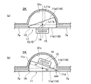
- FIGS. 8A and 8B are schematic diagrams for explaining this rotation. This will be described below with reference to FIG.
- FIG. 8A corresponds to the posture of the door portion 11 shown in FIG. 7 and is a schematic view of the door portion 11 rotated most clockwise as viewed from the upper surface side.
- FIG. 8B is a schematic view of the state in which the door portion 11 is rotated most counterclockwise as viewed from the upper surface side.
- the cradle support surface 11b in the state of FIG. 8 (a) and the decorative surface 11a in the state of FIG. 8 (b) are at the same position. Therefore, in the state of FIG. 8A, the surrounding surface 7a of the dock portion 7 and the cradle support surface 11b are substantially the same surface, and in the state of FIG. 8B, the surrounding surface 7a and the decorative surface 11a of the dock portion 7 are Are almost on the same plane.
- the rotation axis CL12 is positioned such that the distance L11a from the rotation axis CL12 to the decorative surface 11a is equal to the distance L11b from the cradle support surface 11b. It depends on what is set.
- the position of the rotation axis CL12 is located at the midpoint of the distance between the opposing peripheral surface 11c and the end surface 11d. That is, the peripheral surface 11c and the end surface 11d are formed with the same radius R1 around the rotation axis CL12. Accordingly, the positions of the decorative surface 11a and the cradle support surface 11b with respect to the opening 1k are not different from each other in the upper, lower, left, right, forward, and back directions. Therefore, each clearance gap between each surface 11a, 11b and the opening part 1k can be made small, and an external appearance quality can be improved more.
- the inner peripheral surface 31c of the door box portion 31 is also formed in an arc shape centered on the rotation axis CL12.
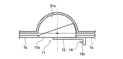
- FIG. 9 is a schematic view of a state in which the cradle 15 is rotated 90 ° counterclockwise with respect to the rotation axis CL15 from the state of FIG. 8A as viewed from the top side (see FIG. 7). .
- the cradle 15 when the cradle 15 is rotated in the state of FIG. 8A, that is, the surrounding surface 7a and the cradle support surface 11b are substantially flush with each other, as shown in FIG.
- the cradle 15 can be rotated so that the shelf 15t of the cradle 15 overlaps the surrounding surface 7a, and can take a horizontal posture without any trouble.
- the decorative surface 11a and the cradle support surface 11b are substantially in the same plane as the surrounding surrounding surface 7a, even when the cradle 15 having the connector 14 is exposed or stored. Is located. Thereby, the appearance quality is improved. Further, when the cradle 15 is rotated, the cradle 15 can project out of the range of the cradle support surface 11b. In other words, the shape can be set in the rotated horizontal posture.
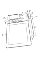
- FIG. 10 is an external perspective view showing a state in which the mobile terminal device is connected and held to the control device 50 which is an example of an electronic apparatus provided with the connector connecting portion CS and the door rotating portion DK described above.
- the control device 50 a tablet-type mobile terminal device TS1 is attached to the left dock region DR1, and a smartphone-type mobile terminal device TS2 is attached to the right dock region DR2.
- the control device 50 can simultaneously mount the mobile terminal devices TS1 and TS2 having different shapes.
- the left dock region DR1 is provided with the connector connecting portion CS in which the position of the connector 13 is free in a predetermined space range, it is possible to connect mobile terminal devices having various shapes, particularly, different thicknesses.
- the right dock region DR2 can hold the position of the connector 14 even in different postures between the vertical posture and the horizontal posture, and is provided with a cradle 15 that protrudes from the surrounding surface 7a as it rotates, so that mobile terminal devices of various shapes Can be connected.
- the control device 50 of the embodiment is stored in the housing without exposing the shape for mounting the connector for connection and the mobile terminal device manufactured around the connector without mounting the mobile terminal device. it can. For this reason, there is no possibility that unexpected and excessive external force is applied to the connector to cause trouble in connection, and the appearance quality of the electronic device can be maintained high.
- the connector connecting part CS is not applied only to the electronic device such as the control device 50, but can be applied without limitation as long as it is a device that connects the connected device to the connector and holds the connected device.
- the angle ⁇ b in the door portion 11 is not limited to 25 ° and can be set arbitrarily.
- the two exposed surfaces 11a and 11b in the door portion 11 described as the decorative surface 11a and the cradle support surface 11b in the embodiment set an arc centered on the rotation axis CL12 when viewed from the rotation axis CL12 side. It is set as two strings that do not cross each other.
- the decorative surface 11a and the cradle support surface 11b include two non-intersecting cut surfaces obtained by cutting a right circular cylinder centered on the rotation axis CL12 along a plane parallel to the rotation axis CL12. It is set as a cutting plane.
- the control device 50 is an example of this. Thereby, it can set so that the magnitude
- the urging member may not be used as the driving force for rotating the door portion 11.
- the structure using the torsion coil spring 11k as the urging member has been described.
- the structure may be rotated by pushing with a finger.
- the center of gravity G of the door portion 11 may be set as follows. A modification will be described in detail with reference to FIGS.
- FIGS. 11A and 11B are schematic diagrams for explaining a modification of the door portion 11.
- Fig.11 (a) is the side view which looked at only the door part 11 from the left side
- FIG.11 (b) is arrow Y1 figure of Fig.11 (a).
- the rotation axis CL12 of the door portion 11 is set to be inclined at an angle ⁇ a in the front-rear direction with respect to the reference surface KM (bottom surface BTM) of the control device 50.
- This angle ⁇ a is the same as the inclination angle of the surrounding surface 7 a of the dock portion 7.
- the door rotation part DK is provided with holding means (such as a latch device) that holds the state where the cradle support surface 11b is exposed and the state where the decorative surface 11a is exposed. Then, when the state in which the exposed cradle support surface 11b is held is released, the door portion 11 naturally rotates at a predetermined angle (for example, about 90 °) to a position where the rotational moment becomes zero. The remaining angle is rotated by a finger and held by the holding means in a state where the decorative surface 11a is exposed.
- a predetermined angle for example, about 90 °
Landscapes
- Engineering & Computer Science (AREA)
- Signal Processing (AREA)
- Human Computer Interaction (AREA)
- Theoretical Computer Science (AREA)
- Computer Networks & Wireless Communication (AREA)
- Computer Hardware Design (AREA)
- Physics & Mathematics (AREA)
- General Engineering & Computer Science (AREA)
- General Physics & Mathematics (AREA)
- Microelectronics & Electronic Packaging (AREA)
- Telephone Set Structure (AREA)
- Casings For Electric Apparatus (AREA)
Priority Applications (3)
| Application Number | Priority Date | Filing Date | Title |
|---|---|---|---|
| EP12782830.9A EP2709343B1 (en) | 2011-05-11 | 2012-05-01 | Electronic device |
| CN201280022661.3A CN103518365B (zh) | 2011-05-11 | 2012-05-01 | 电子设备 |
| US14/073,468 US8861715B2 (en) | 2011-05-11 | 2013-11-06 | Electronic device |
Applications Claiming Priority (2)
| Application Number | Priority Date | Filing Date | Title |
|---|---|---|---|
| JP2011-106061 | 2011-05-11 | ||
| JP2011106061A JP5168385B2 (ja) | 2011-05-11 | 2011-05-11 | 電子機器 |
Related Child Applications (1)
| Application Number | Title | Priority Date | Filing Date |
|---|---|---|---|
| US14/073,468 Continuation US8861715B2 (en) | 2011-05-11 | 2013-11-06 | Electronic device |
Publications (1)
| Publication Number | Publication Date |
|---|---|
| WO2012153679A1 true WO2012153679A1 (ja) | 2012-11-15 |
Family
ID=47139160
Family Applications (1)
| Application Number | Title | Priority Date | Filing Date |
|---|---|---|---|
| PCT/JP2012/061565 Ceased WO2012153679A1 (ja) | 2011-05-11 | 2012-05-01 | 電子機器 |
Country Status (5)
| Country | Link |
|---|---|
| US (1) | US8861715B2 (enExample) |
| EP (1) | EP2709343B1 (enExample) |
| JP (1) | JP5168385B2 (enExample) |
| CN (1) | CN103518365B (enExample) |
| WO (1) | WO2012153679A1 (enExample) |
Families Citing this family (9)
| Publication number | Priority date | Publication date | Assignee | Title |
|---|---|---|---|---|
| US9182793B2 (en) | 2011-10-14 | 2015-11-10 | Ergotron, Inc. | Tablet storage and transportation device |
| JP5448216B1 (ja) * | 2012-09-26 | 2014-03-19 | Necインフロンティア株式会社 | 携帯型情報端末用保持台および卓上電話機 |
| JP6259133B2 (ja) * | 2014-02-28 | 2018-01-10 | アップル インコーポレイテッド | ポータブル電子デバイスの製品デモンストレーション用フィクスチャ |
| JP2016171425A (ja) | 2015-03-12 | 2016-09-23 | パナソニックIpマネジメント株式会社 | クレードル装置 |
| US9727084B2 (en) * | 2015-10-23 | 2017-08-08 | Henge Docks Llc | Drivetrain for a motorized docking station |
| US10306799B2 (en) * | 2015-11-16 | 2019-05-28 | Exascaler Inc. | Electronic device for liquid immersion cooling and cooling system using the same |
| US10481650B2 (en) * | 2015-11-16 | 2019-11-19 | Exascaler Inc. | Electronic device for liquid immersion cooling and cooling system using the same |
| KR102596817B1 (ko) * | 2019-04-11 | 2023-11-01 | 삼성전자주식회사 | 전자 장치 및 그의 송신 전력을 제어하는 방법 |
| USD976253S1 (en) * | 2022-01-25 | 2023-01-24 | Xiaochun Liang | Phone holder |
Citations (2)
| Publication number | Priority date | Publication date | Assignee | Title |
|---|---|---|---|---|
| JP2000115315A (ja) * | 1998-09-30 | 2000-04-21 | Harness Syst Tech Res Ltd | 電話機ホルダー |
| JP4917701B1 (ja) * | 2011-04-06 | 2012-04-18 | パイオニア株式会社 | 電子機器 |
Family Cites Families (8)
| Publication number | Priority date | Publication date | Assignee | Title |
|---|---|---|---|---|
| US6591085B1 (en) * | 2002-07-17 | 2003-07-08 | Netalog, Inc. | FM transmitter and power supply/charging assembly for MP3 player |
| US20040162029A1 (en) | 2002-07-17 | 2004-08-19 | Jeff Grady | Audio player assembly comprising an MP3 player |
| US7230822B2 (en) * | 2004-04-30 | 2007-06-12 | Altec Lansing, A Division Of Plantronics, Inc. | Compact portable media reproduction system |
| KR100663535B1 (ko) * | 2004-05-17 | 2007-01-02 | 삼성전자주식회사 | 휴대 장치의 스피커 겸용 교체성 거치/충전 장치 |
| US8050441B2 (en) * | 2005-06-03 | 2011-11-01 | Creative Technology Ltd | Portable speakers |
| US8103035B2 (en) * | 2006-12-22 | 2012-01-24 | Bose Corporation | Portable audio system having waveguide structure |
| US8145821B2 (en) * | 2008-05-20 | 2012-03-27 | Honeywell International Inc. | Docking station for portable electronic devices |
| JP5242497B2 (ja) * | 2009-05-13 | 2013-07-24 | 株式会社ニフコ | 物品保持具 |
-
2011
- 2011-05-11 JP JP2011106061A patent/JP5168385B2/ja active Active
-
2012
- 2012-05-01 CN CN201280022661.3A patent/CN103518365B/zh active Active
- 2012-05-01 EP EP12782830.9A patent/EP2709343B1/en active Active
- 2012-05-01 WO PCT/JP2012/061565 patent/WO2012153679A1/ja not_active Ceased
-
2013
- 2013-11-06 US US14/073,468 patent/US8861715B2/en active Active
Patent Citations (2)
| Publication number | Priority date | Publication date | Assignee | Title |
|---|---|---|---|---|
| JP2000115315A (ja) * | 1998-09-30 | 2000-04-21 | Harness Syst Tech Res Ltd | 電話機ホルダー |
| JP4917701B1 (ja) * | 2011-04-06 | 2012-04-18 | パイオニア株式会社 | 電子機器 |
Non-Patent Citations (1)
| Title |
|---|
| See also references of EP2709343A4 * |
Also Published As
| Publication number | Publication date |
|---|---|
| EP2709343A4 (en) | 2015-01-14 |
| EP2709343B1 (en) | 2016-06-22 |
| US8861715B2 (en) | 2014-10-14 |
| US20140055933A1 (en) | 2014-02-27 |
| JP2012238999A (ja) | 2012-12-06 |
| EP2709343A1 (en) | 2014-03-19 |
| JP5168385B2 (ja) | 2013-03-21 |
| CN103518365B (zh) | 2015-08-19 |
| CN103518365A (zh) | 2014-01-15 |
Similar Documents
| Publication | Publication Date | Title |
|---|---|---|
| JP5609763B2 (ja) | コネクタ構造及び電子機器 | |
| JP5168385B2 (ja) | 電子機器 | |
| EP2016680B1 (en) | Sliding tilt unit and mobile device using the same | |
| EP2001207B1 (en) | Desktop charger holder | |
| US20110285652A1 (en) | Broadcast receiving device and electronic device | |
| CN108604109B (zh) | 具有支起功能的电子设备 | |
| JP4129003B2 (ja) | 電子機器 | |
| JP5060990B2 (ja) | スタンド及び電子機器 | |
| KR20130038439A (ko) | 휴대용 단말기의 거치대 | |
| JP4555870B2 (ja) | ユニット装着機構 | |
| JP2024109974A (ja) | 保持装置 | |
| US20110285385A1 (en) | Television apparatus and electronic device | |
| JPWO2004099959A1 (ja) | 電子機器およびユニット装着機構 | |
| JP2009151719A (ja) | 携帯型機器 | |
| JP2010171698A (ja) | 携帯端末装置 | |
| JP4206118B1 (ja) | 携帯端末 | |
| JP2006135830A (ja) | 携帯端末 | |
| JP4951142B2 (ja) | テレビジョン装置および電子機器 | |
| JP2014216844A (ja) | 携帯情報端末機用ケース | |
| JP2023061930A (ja) | 保持装置 | |
| JP2025010205A (ja) | 保持装置 | |
| JP2008218520A (ja) | 電子機器およびアクセサリー | |
| JPH09114548A (ja) | 電子機器 | |
| JP2009022624A (ja) | ベッド用コントロールボックス | |
| JP2001014060A (ja) | 小型電子機器およびこれを備えた小型電子機器システム |
Legal Events
| Date | Code | Title | Description |
|---|---|---|---|
| 121 | Ep: the epo has been informed by wipo that ep was designated in this application |
Ref document number: 12782830 Country of ref document: EP Kind code of ref document: A1 |
|
| NENP | Non-entry into the national phase |
Ref country code: DE |
|
| WWE | Wipo information: entry into national phase |
Ref document number: 2012782830 Country of ref document: EP |